EP3619435B1 - Optimised tunnel ventilation device - Google Patents
Optimised tunnel ventilation device Download PDFInfo
- Publication number
- EP3619435B1 EP3619435B1 EP18714336.7A EP18714336A EP3619435B1 EP 3619435 B1 EP3619435 B1 EP 3619435B1 EP 18714336 A EP18714336 A EP 18714336A EP 3619435 B1 EP3619435 B1 EP 3619435B1
- Authority
- EP
- European Patent Office
- Prior art keywords
- fan
- nozzle
- throughbore
- fan assembly
- bellmouth
- Prior art date
- Legal status (The legal status is an assumption and is not a legal conclusion. Google has not performed a legal analysis and makes no representation as to the accuracy of the status listed.)
- Active
Links
Images


Classifications
-
- E—FIXED CONSTRUCTIONS
- E21—EARTH OR ROCK DRILLING; MINING
- E21F—SAFETY DEVICES, TRANSPORT, FILLING-UP, RESCUE, VENTILATION, OR DRAINING IN OR OF MINES OR TUNNELS
- E21F1/00—Ventilation of mines or tunnels; Distribution of ventilating currents
-
- E—FIXED CONSTRUCTIONS
- E21—EARTH OR ROCK DRILLING; MINING
- E21F—SAFETY DEVICES, TRANSPORT, FILLING-UP, RESCUE, VENTILATION, OR DRAINING IN OR OF MINES OR TUNNELS
- E21F1/00—Ventilation of mines or tunnels; Distribution of ventilating currents
- E21F1/003—Ventilation of traffic tunnels
-
- F—MECHANICAL ENGINEERING; LIGHTING; HEATING; WEAPONS; BLASTING
- F04—POSITIVE - DISPLACEMENT MACHINES FOR LIQUIDS; PUMPS FOR LIQUIDS OR ELASTIC FLUIDS
- F04D—NON-POSITIVE-DISPLACEMENT PUMPS
- F04D25/00—Pumping installations or systems
- F04D25/02—Units comprising pumps and their driving means
- F04D25/08—Units comprising pumps and their driving means the working fluid being air, e.g. for ventilation
-
- F—MECHANICAL ENGINEERING; LIGHTING; HEATING; WEAPONS; BLASTING
- F04—POSITIVE - DISPLACEMENT MACHINES FOR LIQUIDS; PUMPS FOR LIQUIDS OR ELASTIC FLUIDS
- F04D—NON-POSITIVE-DISPLACEMENT PUMPS
- F04D29/00—Details, component parts, or accessories
- F04D29/40—Casings; Connections of working fluid
- F04D29/42—Casings; Connections of working fluid for radial or helico-centrifugal pumps
- F04D29/44—Fluid-guiding means, e.g. diffusers
- F04D29/441—Fluid-guiding means, e.g. diffusers especially adapted for elastic fluid pumps
-
- F—MECHANICAL ENGINEERING; LIGHTING; HEATING; WEAPONS; BLASTING
- F04—POSITIVE - DISPLACEMENT MACHINES FOR LIQUIDS; PUMPS FOR LIQUIDS OR ELASTIC FLUIDS
- F04D—NON-POSITIVE-DISPLACEMENT PUMPS
- F04D29/00—Details, component parts, or accessories
- F04D29/40—Casings; Connections of working fluid
- F04D29/52—Casings; Connections of working fluid for axial pumps
- F04D29/54—Fluid-guiding means, e.g. diffusers
- F04D29/541—Specially adapted for elastic fluid pumps
- F04D29/545—Ducts
- F04D29/547—Ducts having a special shape in order to influence fluid flow
-
- F—MECHANICAL ENGINEERING; LIGHTING; HEATING; WEAPONS; BLASTING
- F04—POSITIVE - DISPLACEMENT MACHINES FOR LIQUIDS; PUMPS FOR LIQUIDS OR ELASTIC FLUIDS
- F04D—NON-POSITIVE-DISPLACEMENT PUMPS
- F04D29/00—Details, component parts, or accessories
- F04D29/60—Mounting; Assembling; Disassembling
- F04D29/601—Mounting; Assembling; Disassembling specially adapted for elastic fluid pumps
- F04D29/602—Mounting in cavities
-
- F—MECHANICAL ENGINEERING; LIGHTING; HEATING; WEAPONS; BLASTING
- F05—INDEXING SCHEMES RELATING TO ENGINES OR PUMPS IN VARIOUS SUBCLASSES OF CLASSES F01-F04
- F05D—INDEXING SCHEME FOR ASPECTS RELATING TO NON-POSITIVE-DISPLACEMENT MACHINES OR ENGINES, GAS-TURBINES OR JET-PROPULSION PLANTS
- F05D2250/00—Geometry
- F05D2250/50—Inlet or outlet
- F05D2250/52—Outlet
Definitions
- a previous patent application number GB2512181 filed by the present Applicant describes an improved jetfan, wherein the angle made between the nozzle trailing edge and a centreline of the nozzle is not perpendicular, and wherein at least one of the nozzle throughbore edges is arranged to turn the flow away from the surrounding tunnel surfaces. That invention reduces the Coanda effect of the jet issued from the jetfan, and hence improves the energy efficiency of the tunnel ventilation.
- the tilting of one of the nozzle throughbore edges to turn the flow away from the surrounding tunnel surfaces in GB2512181 has the effect that the nozzle trailing edge must be tilted through a large angle (around 30°), in order to ensure that the aerodynamic throat of the nozzle throughbore is at least equal to the fan area. Since the airflow enters the jetfan in a direction normal to the inlet nozzle plane, such a large nozzle trailing edge angle can cause the flow to separate at the nozzle inlet, causing additional pressure losses.
- JP-A-H1-237400 discloses a jetfan with an undercut on the lower side of the cylindrical casing, to encourage the discharged air to turn away from the tunnel soffit.
- the trailing nozzle trailing edge is shaped as an ellipse, it is not feasible to attach commercially available bellmouths on the nozzle trailing edges, which in turn implies significant pressure losses through the j etfan.
- DE2509279A1 discloses a method of ventilating artificial tunnels constructed for environmental reasons by covering up the roadway with a transparent roof and teaches that adequate ventilation can be arranged by pulling fresh air through the transparent roof via individual fans, and discharging the fresh air into the tunnel.
- EP0410428A2 discloses a method of collecting, filtering and discharging air into a tunnel.
- AT375155B discloses a method by which nozzles can be fitted to one or both sides of a jetfan in a tunnel using diffusers with non-circular cross-sections.
- Preferably two nozzles are provided, one installed on each side of the fan.
- the angle between the trailing edge and a line normal to the centreline of the fan is within the range of 5 to 60 degrees.
- the invention provides a solution to the technical issue of how to turn the flow from a jetfan away from the surrounding tunnel surfaces and hence achieve greater in-tunnel aerodynamic thrust, without increasing the pressure drop through the j etfan.
- the turning of the flow discharged into the tunnel is partially achieved through tilting the nozzle trailing edge.
- the jetfan is arranged with the longer side of the throughbore closer to the surrounding tunnel surface than the shorter side of the throughbore. The tilting of the nozzle trailing edge thus serves to turn the flow away from the surrounding tunnel surface.
- this present invention allows for a larger cross-sectional area through the throughbore, since the area is no longer restricted by an angled throughbore edge.
- smaller tilt angles can be selected for the inlet trailing edge, in order to reduce the likelihood and extent of any inlet flow separation. The power consumption of the jetfan is thus significantly reduced.
- the bellmouth described in this invention is attached to the trailing edge of a nozzle, which is inclined such that the trailing edge is not perpendicular to the centreline of the fan.
- the bellmouth is preferably arranged to be rotationally symmetrical about its own central axis. Such a geometry is readily manufactured using standard spinning production techniques.
- the bellmouth deflects the jet discharged from the longest edge of the nozzle away from the surrounding tunnel surfaces, which reduces the Coanda effect and enhances the in-tunnel thrust.
- the first effect described above can preferably be achieved by arranging the bellmouth throughbore to be substantially parallel to the shortest edge of the nozzle throughbore, at its point of attachment to the nozzle.
- This geometric arrangement implies that the bellmouth throughbore has a convergent cross-sectional area at its point of attachment to the nozzle, in a direction away from the fan.
- the bellmouth throughbore can therefore converge down to a minimum cross-sectional area, whose value is preferably selected with reference to the fan cross-sectional area, so as not to choke the inlet or outlet flow.
- the bellmouth may be arranged in a conventional manner, preferably with a circular or an elliptical-shaped arc increasing the cross-sectional area in the direction away from the fan.
- the present invention has an advantage over GB2512181 in that any length of nozzle can be selected, to suit acoustic silencing requirements.
- the present invention is also simpler and cheaper to manufacture than GB2512181 , because no angling of a throughbore edge is required. Less sheet metal may be required for production of the present invention compared to GB2512181 , because there is less in-plane curvature in the developed flat patterns.
- the present invention does not use a throughbore surface that is cylindrical in shape. This allows better matching of the nozzles to bellmouths.
- the nozzles described in the invention can typically be used for acoustic silencing, as well as for turning the discharged flow away from the tunnel surrounding surfaces.
- FIG. 1 shows a sectional side view of an embodiment which falls outside of the scope of the claims within a bidirectional ventilation apparatus installed underneath a tunnel soffit, which is designed to operate in a fully reversible manner.
- a fan assembly comprising a fan rotor (3) driven by a motor (4) is installed within a fan housing (2).
- the fan rotor (3) is mounted along the fan centreline (7).
- Airflow (5) enters the fan rotor (3) through a bellmouth (1) and an inlet nozzle throughbore (8), before being discharged thorough an outlet nozzle throughbore (9) and a bellmouth (1).
- the inlet and outlet trailing edges of the nozzle (6) are tilted at an angle (13) with respect to the normal to the fan centreline (7).
- the discharged airflow is turned by the upper surface of the bellmouth (1) in a direction away from the tunnel surfaces, hence reducing the Coanda effect.
- the angle (13) is between 5 degrees and 60 degrees. Preferably still, the angle (13) is approximately 25 degrees.
- a larger geometric throat (14) can be arranged at both the inlet and discharge sides of the nozzle, by tilting the nozzle trailing edge (6) by the angle (13) between the normal to the throughbore (14) and the trailing edge (6).
- the trailing edge (6) can thereby increase in length.
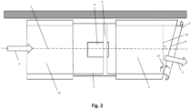
- Figure 2 shows a side view of a particular embodiment which falls outside of the scope of the claims and which would normally (but not exclusively) be operated in a unidirectional manner.
- the indicated airflow direction is from left to right, i.e. the airflow (5) enters into a conventional nozzle (16) first, prior to being accelerated by the fan rotor (3) into a shaped nozzle with an outlet throughbore (9).
- the discharged flow is turned by the upper surface of the bellmouth (1).
- the bellmouth (1) is installed at an angle (13) with respect to the normal to the fan centreline (7), such that in use, the discharged air flows away from the surrounding tunnel surfaces.
- FIG 3 shows a horizontal sectional view of an embodiment of this invention
- the sidewalls of the throughbore diverge at an angle (15) with respect to lines parallel to the fan centreline (7).
- This underlines the non-cylindrical nature of the throughbore surface, and highlights the increase in flow area at the inlet and outlet planes (14).
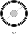
- Fig. 4 shows an end view through an embodiment of a ventilation apparatus, with the edge of the nozzle throughbore at the distal end from the fan in the form of a circle with a specified diameter (17).
- This invention is equally beneficial for the ventilation of tunnels, underground car parks and similar internal spaces.
Landscapes
- Engineering & Computer Science (AREA)
- Mechanical Engineering (AREA)
- General Engineering & Computer Science (AREA)
- Mining & Mineral Resources (AREA)
- Geochemistry & Mineralogy (AREA)
- General Life Sciences & Earth Sciences (AREA)
- Life Sciences & Earth Sciences (AREA)
- Geology (AREA)
- Physics & Mathematics (AREA)
- Fluid Mechanics (AREA)
- Structures Of Non-Positive Displacement Pumps (AREA)
- Ventilation (AREA)
- Air-Conditioning For Vehicles (AREA)
Description
- Longitudinal ventilation by jetfans is a well-established technique for establishing airflows in tunnels and car parks, for the improvement of air quality during normal and congested operations, as well as for the control of smoke during fires.
- A previous patent application number
GB2512181 - The tilting of one of the nozzle throughbore edges to turn the flow away from the surrounding tunnel surfaces in
GB2512181 -
JP-A-H1-237400 -
DE2509279A1 discloses a method of ventilating artificial tunnels constructed for environmental reasons by covering up the roadway with a transparent roof and teaches that adequate ventilation can be arranged by pulling fresh air through the transparent roof via individual fans, and discharging the fresh air into the tunnel. -
EP0410428A2 discloses a method of collecting, filtering and discharging air into a tunnel. -
AT375155B - The Applicant believes that there remains scope to improve the energy efficiency of longitudinal tunnel ventilation systems.
- According to the invention, there is provided a fan assembly as defined in
claim 1. Preferred embodiments are defined inclaims 2 to 9. - Preferably two nozzles are provided, one installed on each side of the fan.
- Preferably the angle between the trailing edge and a line normal to the centreline of the fan is within the range of 5 to 60 degrees.
- The invention provides a solution to the technical issue of how to turn the flow from a jetfan away from the surrounding tunnel surfaces and hence achieve greater in-tunnel aerodynamic thrust, without increasing the pressure drop through the j etfan.
- The turning of the flow discharged into the tunnel is partially achieved through tilting the nozzle trailing edge. The jetfan is arranged with the longer side of the throughbore closer to the surrounding tunnel surface than the shorter side of the throughbore. The tilting of the nozzle trailing edge thus serves to turn the flow away from the surrounding tunnel surface.
- Compared to
GB2512181 - The bellmouth described in this invention is attached to the trailing edge of a nozzle, which is inclined such that the trailing edge is not perpendicular to the centreline of the fan.
- The bellmouth is preferably arranged to be rotationally symmetrical about its own central axis. Such a geometry is readily manufactured using standard spinning production techniques.
- The bellmouth described in this invention improves thrust and reduces power consumption through two effects.
- Firstly, it can ensure smooth flow along the shortest edge of the nozzle throughbore inlet, thereby avoiding flow separation.
- Secondly, the bellmouth deflects the jet discharged from the longest edge of the nozzle away from the surrounding tunnel surfaces, which reduces the Coanda effect and enhances the in-tunnel thrust.
- The first effect described above can preferably be achieved by arranging the bellmouth throughbore to be substantially parallel to the shortest edge of the nozzle throughbore, at its point of attachment to the nozzle. This geometric arrangement implies that the bellmouth throughbore has a convergent cross-sectional area at its point of attachment to the nozzle, in a direction away from the fan. The bellmouth throughbore can therefore converge down to a minimum cross-sectional area, whose value is preferably selected with reference to the fan cross-sectional area, so as not to choke the inlet or outlet flow.
- Beyond the minimum bellmouth cross-sectional area, the bellmouth may be arranged in a conventional manner, preferably with a circular or an elliptical-shaped arc increasing the cross-sectional area in the direction away from the fan.
- Contrary to
GB2512181 - The present invention has an advantage over
GB2512181 GB2512181 GB2512181 - Contrary to the teaching of
JP-A-H1-237400 - By using trailing edges in the shape of a circle, circular bellmouths can be attached to the nozzle inlet. Such bellmouths can be readily manufactured using spinning production techniques.
- The nozzles described in the invention can typically be used for acoustic silencing, as well as for turning the discharged flow away from the tunnel surrounding surfaces.
- A number of preferred embodiments of the present invention will now be described by way of example only, and with reference to the accompanying drawings, in which:
- Like reference numerals are used for like components throughout the figures;
-
Fig.1 shows a vertical section through an embodiment of a ventilation apparatus with nozzles installed on both sides of a fan which falls outside of the scope of the claims; -
Fig. 2 shows an embodiment of a ventilation apparatus with a nozzle installed on one side of a fan which falls outside of the scope of the claims; -
Fig. 3 shows a horizontal section through an embodiment of a ventilation apparatus with nozzles as described in this invention installed on both sides of a fan; and -
Fig. 4 shows an end view through an embodiment of a ventilation apparatus. - Referring to
Figure 1 , this shows a sectional side view of an embodiment which falls outside of the scope of the claims within a bidirectional ventilation apparatus installed underneath a tunnel soffit, which is designed to operate in a fully reversible manner. - In this embodiment, a fan assembly comprising a fan rotor (3) driven by a motor (4) is installed within a fan housing (2). The fan rotor (3) is mounted along the fan centreline (7).
- Airflow (5) enters the fan rotor (3) through a bellmouth (1) and an inlet nozzle throughbore (8), before being discharged thorough an outlet nozzle throughbore (9) and a bellmouth (1). The inlet and outlet trailing edges of the nozzle (6) are tilted at an angle (13) with respect to the normal to the fan centreline (7). The discharged airflow is turned by the upper surface of the bellmouth (1) in a direction away from the tunnel surfaces, hence reducing the Coanda effect.
- Preferably, the angle (13) is between 5 degrees and 60 degrees. Preferably still, the angle (13) is approximately 25 degrees.
- A larger geometric throat (14) can be arranged at both the inlet and discharge sides of the nozzle, by tilting the nozzle trailing edge (6) by the angle (13) between the normal to the throughbore (14) and the trailing edge (6). The trailing edge (6) can thereby increase in length.
- We refer now to
Figure 2 , which shows a side view of a particular embodiment which falls outside of the scope of the claims and which would normally (but not exclusively) be operated in a unidirectional manner. - In this embodiment, the indicated airflow direction is from left to right, i.e. the airflow (5) enters into a conventional nozzle (16) first, prior to being accelerated by the fan rotor (3) into a shaped nozzle with an outlet throughbore (9). The discharged flow is turned by the upper surface of the bellmouth (1). The bellmouth (1) is installed at an angle (13) with respect to the normal to the fan centreline (7), such that in use, the discharged air flows away from the surrounding tunnel surfaces.
- In
Figure 2 , the flow direction can if necessary be reversed by running the fan rotor in the opposite direction. Due to the increased Coanda effect, a reduction of the in-tunnel aerodynamic thrust can be expected in the reverse flow direction (i.e. from right to left) in the embodiment described inFig. 2 . - Referring now to
Figure 3 , which shows a horizontal sectional view of an embodiment of this invention, it can be seen that the sidewalls of the throughbore diverge at an angle (15) with respect to lines parallel to the fan centreline (7). This underlines the non-cylindrical nature of the throughbore surface, and highlights the increase in flow area at the inlet and outlet planes (14). -
Fig. 4 shows an end view through an embodiment of a ventilation apparatus, with the edge of the nozzle throughbore at the distal end from the fan in the form of a circle with a specified diameter (17). - It would be possible to modify an existing fan assembly in order to fit nozzles as described in this invention to one or more sides of a fan, and hence reap the benefits of improved performance.
- This invention is equally beneficial for the ventilation of tunnels, underground car parks and similar internal spaces.
- It will be appreciated that the foregoing merely provides illustrations of embodiments and just some examples of their use. The skilled reader will readily understand that modifications can be made thereto without departing from the true scope of the invention, which is solely defined by the appended claims.
Claims (9)
- A fan assembly for installation in an internal space to provide ventilation in the internal space, the fan assembly comprising:a fan rotor (3) for generating a ventilating flow, the inflow into the fan rotor being substantially parallel to the outflow from the fan rotor;a nozzle throughbore (9) having an edge which, in use, is in proximity to a surrounding surface in which the fan assembly is installed, wherein said nozzle throughbore edge is not arranged to direct the flow away from the surrounding surface of the internal space when air is supplied from the fan rotor (3),wherein:the nozzle throughbore has a trailing edge (6) at a distal end from the fan, an angle made between the nozzle trailing edge (6) and a centreline of the fan (7) being not perpendicular;the fan assembly is arranged or arrangeable such that a ventilating flow generated by the fan will pass through the nozzle before exiting the assembly to enter a space to be ventilated;characterised in thatthe sidewalls of the nozzle throughbore diverge at an angle with respect to the fan centreline;the nozzle throughbore trailing edge is formed as a circle; and a bellmouth (1) extends from the nozzle trailing edge.
- A fan assembly according to claim 1, having a nozzle installed on each side of a fan.
- A fan assembly according to claim 1 or claim 2, wherein the angle between the trailing edge and a line normal to the fan centreline is within the range of 5 to 60 degrees.
- A fan assembly according to any one of claims 1 to 3, wherein the cross-sectional area of the bellmouth throughbore decreases from the location of its attachment to the nozzle in the direction away from the fan, to a minimum cross-sectional area.
- A fan assembly according to claim 4, wherein the cross-sectional area of the bellmouth throughbore decreases from the distal end from the fan, in the direction towards the fan.
- A fan assembly according to any one of claims 4 or 5, wherein the bellmouth is rotationally symmetrical about its own central axis.
- A fan assembly according to any one of claims 4 to 6,wherein the bellmouth throughbore is arranged to be parallel to a shortest edge of the nozzle throughbore, at its point of attachment to the nozzle.
- A fan assembly according to any one of claims 6 or 7, wherein the bellmouth is arranged to form a part of an elliptical arc at the distal end from the fan.
- A fan assembly according to one of claims 6 to 8 having two bellmouths, one installed on each side of the fan assembly.
Applications Claiming Priority (3)
| Application Number | Priority Date | Filing Date | Title |
|---|---|---|---|
| GB1707147.3A GB2562091A (en) | 2017-05-04 | 2017-05-04 | Optimised tunnel ventilation device |
| GB1707467.5A GB2562263A (en) | 2017-05-10 | 2017-05-10 | Bellmouth for jetfan |
| PCT/GB2018/000029 WO2018203023A1 (en) | 2017-05-04 | 2018-02-21 | Optimised tunnel ventilation device |
Publications (3)
| Publication Number | Publication Date |
|---|---|
| EP3619435A1 EP3619435A1 (en) | 2020-03-11 |
| EP3619435B1 true EP3619435B1 (en) | 2024-09-11 |
| EP3619435C0 EP3619435C0 (en) | 2024-09-11 |
Family
ID=61827771
Family Applications (1)
| Application Number | Title | Priority Date | Filing Date |
|---|---|---|---|
| EP18714336.7A Active EP3619435B1 (en) | 2017-05-04 | 2018-02-21 | Optimised tunnel ventilation device |
Country Status (9)
| Country | Link |
|---|---|
| US (1) | US11655712B2 (en) |
| EP (1) | EP3619435B1 (en) |
| JP (1) | JP7276857B2 (en) |
| KR (2) | KR102864806B1 (en) |
| CN (2) | CN120650257A (en) |
| AU (1) | AU2018263370B2 (en) |
| CA (1) | CA3057405C (en) |
| ES (1) | ES2995964T3 (en) |
| WO (1) | WO2018203023A1 (en) |
Families Citing this family (6)
| Publication number | Priority date | Publication date | Assignee | Title |
|---|---|---|---|---|
| CN120650257A (en) | 2017-05-04 | 2025-09-16 | 摩森有限公司 | Fan assembly |
| IT201900015345A1 (en) * | 2019-09-02 | 2021-03-02 | Carpenteria Leggera Aerotecnica C L A S R L | Silencer for fans, particularly for car tunnels and the like. |
| DE102020107955A1 (en) * | 2020-03-23 | 2021-09-23 | W & S Management Gmbh & Co. Kg | Jet fan for ventilation of tunnels, jet fan system and processes |
| GB2597442B (en) * | 2020-06-25 | 2023-03-22 | Mosen Ltd | Vortex generators for jet fans |
| CN112197390B (en) * | 2020-11-13 | 2024-07-23 | 黄河勘测规划设计研究院有限公司 | Fire protection system for pedestrian passageway in high-density dark tunnel |
| GB202401962D0 (en) * | 2024-02-13 | 2024-03-27 | Mosen Ltd | Bullnose bellmouth for jet fan |
Citations (5)
| Publication number | Priority date | Publication date | Assignee | Title |
|---|---|---|---|---|
| JPH01237400A (en) | 1988-03-18 | 1989-09-21 | Hitachi Ltd | Reversible axial blower |
| WO2010046668A1 (en) | 2008-10-24 | 2010-04-29 | Mosen Ltd | Improved tunnel ventilation device |
| WO2014111679A1 (en) | 2013-01-17 | 2014-07-24 | Mosen Ltd | Energy-efficient tunnel ventilation device |
| CN205559315U (en) | 2016-03-09 | 2016-09-07 | 天津中隧通风机有限公司 | Induced draught machine |
| WO2018203023A1 (en) | 2017-05-04 | 2018-11-08 | Mosen Ltd | Optimised tunnel ventilation device |
Family Cites Families (15)
| Publication number | Priority date | Publication date | Assignee | Title |
|---|---|---|---|---|
| DE2509279A1 (en) | 1975-03-04 | 1976-09-16 | Voith Getriebe Kg | Ventilation equipment for covered roads - has axial flow intake fans supplying fresh sir to road covering |
| AT375155B (en) * | 1982-07-05 | 1984-07-10 | Reinhard Dipl Ing Dr Te Pinter | JET FAN, ESPECIALLY FOR USE IN TUNNEL BUILDINGS |
| JPH01275900A (en) * | 1988-04-25 | 1989-11-06 | Matsushita Electric Ind Co Ltd | tunnel ventilation fan |
| EP0410428B1 (en) * | 1989-07-26 | 1996-10-09 | Fuji Electric Co., Ltd. | Tunnel dust collecting system |
| JPH1066828A (en) * | 1996-08-29 | 1998-03-10 | Hitachi Ltd | Air purification ventilator, silent discharge device used for the same, air purification ventilation method |
| JPH1123032A (en) * | 1997-06-30 | 1999-01-26 | Mitsubishi Heavy Ind Ltd | Fan device for ventilating tunnel |
| DE19920513A1 (en) | 1999-05-05 | 2000-11-09 | Witt & Sohn Gmbh & Co | Jet fan |
| DE29924674U1 (en) | 1999-05-05 | 2004-10-07 | Witt & Sohn Ag | Radiation fan for ventilating tunnels has at least one fan arranged in shaft and at least one nozzle arrangement fitted at inlet and/or outlet side of shaft and preferably provided with noise damper |
| KR100960883B1 (en) * | 2008-01-29 | 2010-06-04 | 세원시스템벤트 주식회사 | Improved jet fan |
| GB2479082A (en) | 2008-10-24 | 2011-09-28 | Fathi Tarada | Tunnel Ventilation Fan Nozzle |
| CN201826127U (en) | 2010-08-03 | 2011-05-11 | 上海贵衣缝纫设备有限公司 | Pneumatic type automatic belt loop machine |
| JP2013087641A (en) * | 2011-10-14 | 2013-05-13 | Panasonic Corp | Jet fan |
| US8863896B1 (en) | 2013-04-05 | 2014-10-21 | Kai Kang | Vectorized jet fan |
| CN103307003A (en) * | 2013-06-20 | 2013-09-18 | 江苏中联风能机械有限公司 | Subway tunnel fan with inlet and outlet having high sound insulation performances |
| CN105090075A (en) * | 2015-07-16 | 2015-11-25 | 莫森有限责任公司 | Energy-saving tunnel ventilation device |
-
2018
- 2018-02-21 CN CN202510893584.8A patent/CN120650257A/en active Pending
- 2018-02-21 WO PCT/GB2018/000029 patent/WO2018203023A1/en not_active Ceased
- 2018-02-21 KR KR1020247017110A patent/KR102864806B1/en active Active
- 2018-02-21 CA CA3057405A patent/CA3057405C/en active Active
- 2018-02-21 JP JP2019548899A patent/JP7276857B2/en active Active
- 2018-02-21 AU AU2018263370A patent/AU2018263370B2/en active Active
- 2018-02-21 CN CN201880021742.9A patent/CN110741166A/en active Pending
- 2018-02-21 ES ES18714336T patent/ES2995964T3/en active Active
- 2018-02-21 KR KR1020197030636A patent/KR20200003792A/en not_active Ceased
- 2018-02-21 EP EP18714336.7A patent/EP3619435B1/en active Active
- 2018-02-21 US US16/608,943 patent/US11655712B2/en active Active
Patent Citations (6)
| Publication number | Priority date | Publication date | Assignee | Title |
|---|---|---|---|---|
| JPH01237400A (en) | 1988-03-18 | 1989-09-21 | Hitachi Ltd | Reversible axial blower |
| WO2010046668A1 (en) | 2008-10-24 | 2010-04-29 | Mosen Ltd | Improved tunnel ventilation device |
| WO2014111679A1 (en) | 2013-01-17 | 2014-07-24 | Mosen Ltd | Energy-efficient tunnel ventilation device |
| GB2512181A (en) * | 2013-01-17 | 2014-09-24 | Mosen Ltd | Energy-efficient ventilation device |
| CN205559315U (en) | 2016-03-09 | 2016-09-07 | 天津中隧通风机有限公司 | Induced draught machine |
| WO2018203023A1 (en) | 2017-05-04 | 2018-11-08 | Mosen Ltd | Optimised tunnel ventilation device |
Also Published As
| Publication number | Publication date |
|---|---|
| CN110741166A (en) | 2020-01-31 |
| JP2020519800A (en) | 2020-07-02 |
| EP3619435C0 (en) | 2024-09-11 |
| US20200182056A1 (en) | 2020-06-11 |
| ES2995964T3 (en) | 2025-02-11 |
| WO2018203023A1 (en) | 2018-11-08 |
| EP3619435A1 (en) | 2020-03-11 |
| AU2018263370B2 (en) | 2023-10-12 |
| KR102864806B1 (en) | 2025-10-13 |
| KR20200003792A (en) | 2020-01-10 |
| CN120650257A (en) | 2025-09-16 |
| CA3057405A1 (en) | 2018-11-08 |
| US11655712B2 (en) | 2023-05-23 |
| CA3057405C (en) | 2021-10-26 |
| AU2018263370A1 (en) | 2019-09-26 |
| KR20240093882A (en) | 2024-06-24 |
| JP7276857B2 (en) | 2023-05-18 |
Similar Documents
| Publication | Publication Date | Title |
|---|---|---|
| EP3619435B1 (en) | Optimised tunnel ventilation device | |
| EP2946118B1 (en) | Energy-efficient tunnel ventilation device | |
| KR101210696B1 (en) | centrifugal fan | |
| KR101255739B1 (en) | The induced fan for two impeller for jet fan of track type supply air outlet | |
| CN101925783A (en) | Air conditioner | |
| GB2562263A (en) | Bellmouth for jetfan | |
| GB2562091A (en) | Optimised tunnel ventilation device | |
| KR101435007B1 (en) | Noise reduction Louver | |
| JP4839901B2 (en) | Jet fan | |
| RU2648788C1 (en) | Method of ventilating blind working | |
| WO2016121144A1 (en) | Propeller fan, blower, and outdoor unit of refrigeration cycle device | |
| EP4617505A1 (en) | Air movement apparatus | |
| EP4172506A2 (en) | Vortex generators for jet fans | |
| JP5812572B2 (en) | Axial flow fan and outdoor unit of air conditioner using this axial flow fan | |
| GB2639059A (en) | Bullnose bellmouth for a jetfan | |
| WO2025172681A1 (en) | Bullnose bellmouth for jet fan | |
| CN210152978U (en) | The volute, volute, cross-flow fan and air-conditioning indoor unit of the cross-flow fan | |
| GB2599949A (en) | Aerodynamic spoiler for jetfan bellmouth | |
| JP2002349486A (en) | Centrifugal blower | |
| CN1987278A (en) | Integrated air conditioner cover |
Legal Events
| Date | Code | Title | Description |
|---|---|---|---|
| STAA | Information on the status of an ep patent application or granted ep patent |
Free format text: STATUS: UNKNOWN |
|
| STAA | Information on the status of an ep patent application or granted ep patent |
Free format text: STATUS: THE INTERNATIONAL PUBLICATION HAS BEEN MADE |
|
| PUAI | Public reference made under article 153(3) epc to a published international application that has entered the european phase |
Free format text: ORIGINAL CODE: 0009012 |
|
| STAA | Information on the status of an ep patent application or granted ep patent |
Free format text: STATUS: REQUEST FOR EXAMINATION WAS MADE |
|
| 17P | Request for examination filed |
Effective date: 20191128 |
|
| AK | Designated contracting states |
Kind code of ref document: A1 Designated state(s): AL AT BE BG CH CY CZ DE DK EE ES FI FR GB GR HR HU IE IS IT LI LT LU LV MC MK MT NL NO PL PT RO RS SE SI SK SM TR |
|
| AX | Request for extension of the european patent |
Extension state: BA ME |
|
| DAV | Request for validation of the european patent (deleted) | ||
| DAX | Request for extension of the european patent (deleted) | ||
| STAA | Information on the status of an ep patent application or granted ep patent |
Free format text: STATUS: EXAMINATION IS IN PROGRESS |
|
| 17Q | First examination report despatched |
Effective date: 20220411 |
|
| GRAP | Despatch of communication of intention to grant a patent |
Free format text: ORIGINAL CODE: EPIDOSNIGR1 |
|
| STAA | Information on the status of an ep patent application or granted ep patent |
Free format text: STATUS: GRANT OF PATENT IS INTENDED |
|
| INTG | Intention to grant announced |
Effective date: 20240402 |
|
| GRAS | Grant fee paid |
Free format text: ORIGINAL CODE: EPIDOSNIGR3 |
|
| GRAA | (expected) grant |
Free format text: ORIGINAL CODE: 0009210 |
|
| STAA | Information on the status of an ep patent application or granted ep patent |
Free format text: STATUS: THE PATENT HAS BEEN GRANTED |
|
| AK | Designated contracting states |
Kind code of ref document: B1 Designated state(s): AL AT BE BG CH CY CZ DE DK EE ES FI FR GB GR HR HU IE IS IT LI LT LU LV MC MK MT NL NO PL PT RO RS SE SI SK SM TR |
|
| REG | Reference to a national code |
Ref country code: GB Ref legal event code: FG4D |
|
| REG | Reference to a national code |
Ref country code: CH Ref legal event code: EP |
|
| REG | Reference to a national code |
Ref country code: DE Ref legal event code: R096 Ref document number: 602018074217 Country of ref document: DE |
|
| REG | Reference to a national code |
Ref country code: IE Ref legal event code: FG4D |
|
| U01 | Request for unitary effect filed |
Effective date: 20240925 |
|
| U07 | Unitary effect registered |
Designated state(s): AT BE BG DE DK EE FI FR IT LT LU LV MT NL PT RO SE SI Effective date: 20241001 |
|
| PG25 | Lapsed in a contracting state [announced via postgrant information from national office to epo] |
Ref country code: NO Free format text: LAPSE BECAUSE OF FAILURE TO SUBMIT A TRANSLATION OF THE DESCRIPTION OR TO PAY THE FEE WITHIN THE PRESCRIBED TIME-LIMIT Effective date: 20241211 |
|
| PG25 | Lapsed in a contracting state [announced via postgrant information from national office to epo] |
Ref country code: GR Free format text: LAPSE BECAUSE OF FAILURE TO SUBMIT A TRANSLATION OF THE DESCRIPTION OR TO PAY THE FEE WITHIN THE PRESCRIBED TIME-LIMIT Effective date: 20241212 |
|
| PG25 | Lapsed in a contracting state [announced via postgrant information from national office to epo] |
Ref country code: HR Free format text: LAPSE BECAUSE OF FAILURE TO SUBMIT A TRANSLATION OF THE DESCRIPTION OR TO PAY THE FEE WITHIN THE PRESCRIBED TIME-LIMIT Effective date: 20240911 |
|
| PG25 | Lapsed in a contracting state [announced via postgrant information from national office to epo] |
Ref country code: RS Free format text: LAPSE BECAUSE OF FAILURE TO SUBMIT A TRANSLATION OF THE DESCRIPTION OR TO PAY THE FEE WITHIN THE PRESCRIBED TIME-LIMIT Effective date: 20241211 |
|
| PG25 | Lapsed in a contracting state [announced via postgrant information from national office to epo] |
Ref country code: RS Free format text: LAPSE BECAUSE OF FAILURE TO SUBMIT A TRANSLATION OF THE DESCRIPTION OR TO PAY THE FEE WITHIN THE PRESCRIBED TIME-LIMIT Effective date: 20241211 Ref country code: NO Free format text: LAPSE BECAUSE OF FAILURE TO SUBMIT A TRANSLATION OF THE DESCRIPTION OR TO PAY THE FEE WITHIN THE PRESCRIBED TIME-LIMIT Effective date: 20241211 Ref country code: HR Free format text: LAPSE BECAUSE OF FAILURE TO SUBMIT A TRANSLATION OF THE DESCRIPTION OR TO PAY THE FEE WITHIN THE PRESCRIBED TIME-LIMIT Effective date: 20240911 Ref country code: GR Free format text: LAPSE BECAUSE OF FAILURE TO SUBMIT A TRANSLATION OF THE DESCRIPTION OR TO PAY THE FEE WITHIN THE PRESCRIBED TIME-LIMIT Effective date: 20241212 |
|
| REG | Reference to a national code |
Ref country code: ES Ref legal event code: FG2A Ref document number: 2995964 Country of ref document: ES Kind code of ref document: T3 Effective date: 20250211 |
|
| U20 | Renewal fee for the european patent with unitary effect paid |
Year of fee payment: 8 Effective date: 20250225 |
|
| PG25 | Lapsed in a contracting state [announced via postgrant information from national office to epo] |
Ref country code: IS Free format text: LAPSE BECAUSE OF FAILURE TO SUBMIT A TRANSLATION OF THE DESCRIPTION OR TO PAY THE FEE WITHIN THE PRESCRIBED TIME-LIMIT Effective date: 20250111 |
|
| PG25 | Lapsed in a contracting state [announced via postgrant information from national office to epo] |
Ref country code: SM Free format text: LAPSE BECAUSE OF FAILURE TO SUBMIT A TRANSLATION OF THE DESCRIPTION OR TO PAY THE FEE WITHIN THE PRESCRIBED TIME-LIMIT Effective date: 20240911 |
|
| PGFP | Annual fee paid to national office [announced via postgrant information from national office to epo] |
Ref country code: ES Payment date: 20250311 Year of fee payment: 8 |
|
| PG25 | Lapsed in a contracting state [announced via postgrant information from national office to epo] |
Ref country code: PL Free format text: LAPSE BECAUSE OF FAILURE TO SUBMIT A TRANSLATION OF THE DESCRIPTION OR TO PAY THE FEE WITHIN THE PRESCRIBED TIME-LIMIT Effective date: 20240911 Ref country code: CZ Free format text: LAPSE BECAUSE OF FAILURE TO SUBMIT A TRANSLATION OF THE DESCRIPTION OR TO PAY THE FEE WITHIN THE PRESCRIBED TIME-LIMIT Effective date: 20240911 |
|
| PG25 | Lapsed in a contracting state [announced via postgrant information from national office to epo] |
Ref country code: SK Free format text: LAPSE BECAUSE OF FAILURE TO SUBMIT A TRANSLATION OF THE DESCRIPTION OR TO PAY THE FEE WITHIN THE PRESCRIBED TIME-LIMIT Effective date: 20240911 |
|
| PGFP | Annual fee paid to national office [announced via postgrant information from national office to epo] |
Ref country code: GB Payment date: 20250214 Year of fee payment: 8 |
|
| PGFP | Annual fee paid to national office [announced via postgrant information from national office to epo] |
Ref country code: TR Payment date: 20250220 Year of fee payment: 8 |
|
| PLBI | Opposition filed |
Free format text: ORIGINAL CODE: 0009260 |
|
| PLAX | Notice of opposition and request to file observation + time limit sent |
Free format text: ORIGINAL CODE: EPIDOSNOBS2 |
|
| 26 | Opposition filed |
Opponent name: W & S MANAGEMENT GMBH & CO. KG Effective date: 20250611 |
|
| PG25 | Lapsed in a contracting state [announced via postgrant information from national office to epo] |
Ref country code: MC Free format text: LAPSE BECAUSE OF FAILURE TO SUBMIT A TRANSLATION OF THE DESCRIPTION OR TO PAY THE FEE WITHIN THE PRESCRIBED TIME-LIMIT Effective date: 20240911 |
|
| REG | Reference to a national code |
Ref country code: CH Ref legal event code: PL |
|
| PLBB | Reply of patent proprietor to notice(s) of opposition received |
Free format text: ORIGINAL CODE: EPIDOSNOBS3 |
|
| PG25 | Lapsed in a contracting state [announced via postgrant information from national office to epo] |
Ref country code: CH Free format text: LAPSE BECAUSE OF NON-PAYMENT OF DUE FEES Effective date: 20250228 |