EP3619149B1 - Tray conveyor driven by brushless dc motor - Google Patents
Tray conveyor driven by brushless dc motor Download PDFInfo
- Publication number
- EP3619149B1 EP3619149B1 EP18794640.5A EP18794640A EP3619149B1 EP 3619149 B1 EP3619149 B1 EP 3619149B1 EP 18794640 A EP18794640 A EP 18794640A EP 3619149 B1 EP3619149 B1 EP 3619149B1
- Authority
- EP
- European Patent Office
- Prior art keywords
- tray
- rails
- carriage
- conveyor
- diverter
- Prior art date
- Legal status (The legal status is an assumption and is not a legal conclusion. Google has not performed a legal analysis and makes no representation as to the accuracy of the status listed.)
- Active
Links
Images


Classifications
-
- B—PERFORMING OPERATIONS; TRANSPORTING
- B65—CONVEYING; PACKING; STORING; HANDLING THIN OR FILAMENTARY MATERIAL
- B65G—TRANSPORT OR STORAGE DEVICES, e.g. CONVEYORS FOR LOADING OR TIPPING, SHOP CONVEYOR SYSTEMS OR PNEUMATIC TUBE CONVEYORS
- B65G54/00—Non-mechanical conveyors not otherwise provided for
- B65G54/02—Non-mechanical conveyors not otherwise provided for electrostatic, electric, or magnetic
-
- H—ELECTRICITY
- H02—GENERATION; CONVERSION OR DISTRIBUTION OF ELECTRIC POWER
- H02K—DYNAMO-ELECTRIC MACHINES
- H02K11/00—Structural association of dynamo-electric machines with electric components or with devices for shielding, monitoring or protection
- H02K11/0094—Structural association with other electrical or electronic devices
-
- H—ELECTRICITY
- H02—GENERATION; CONVERSION OR DISTRIBUTION OF ELECTRIC POWER
- H02K—DYNAMO-ELECTRIC MACHINES
- H02K29/00—Motors or generators having non-mechanical commutating devices, e.g. discharge tubes or semiconductor devices
- H02K29/06—Motors or generators having non-mechanical commutating devices, e.g. discharge tubes or semiconductor devices with position sensing devices
- H02K29/08—Motors or generators having non-mechanical commutating devices, e.g. discharge tubes or semiconductor devices with position sensing devices using magnetic effect devices, e.g. Hall-plates, magneto-resistors
-
- H—ELECTRICITY
- H02—GENERATION; CONVERSION OR DISTRIBUTION OF ELECTRIC POWER
- H02K—DYNAMO-ELECTRIC MACHINES
- H02K3/00—Details of windings
- H02K3/46—Fastening of windings on the stator or rotor structure
- H02K3/47—Air-gap windings, i.e. iron-free windings
-
- H—ELECTRICITY
- H02—GENERATION; CONVERSION OR DISTRIBUTION OF ELECTRIC POWER
- H02K—DYNAMO-ELECTRIC MACHINES
- H02K41/00—Propulsion systems in which a rigid body is moved along a path due to dynamo-electric interaction between the body and a magnetic field travelling along the path
- H02K41/02—Linear motors; Sectional motors
- H02K41/035—DC motors; Unipolar motors
- H02K41/0352—Unipolar motors
- H02K41/0354—Lorentz force motors, e.g. voice coil motors
- H02K41/0356—Lorentz force motors, e.g. voice coil motors moving along a straight path
-
- B—PERFORMING OPERATIONS; TRANSPORTING
- B60—VEHICLES IN GENERAL
- B60L—PROPULSION OF ELECTRICALLY-PROPELLED VEHICLES; SUPPLYING ELECTRIC POWER FOR AUXILIARY EQUIPMENT OF ELECTRICALLY-PROPELLED VEHICLES; ELECTRODYNAMIC BRAKE SYSTEMS FOR VEHICLES IN GENERAL; MAGNETIC SUSPENSION OR LEVITATION FOR VEHICLES; MONITORING OPERATING VARIABLES OF ELECTRICALLY-PROPELLED VEHICLES; ELECTRIC SAFETY DEVICES FOR ELECTRICALLY-PROPELLED VEHICLES
- B60L13/00—Electric propulsion for monorail vehicles, suspension vehicles or rack railways; Magnetic suspension or levitation for vehicles
- B60L13/03—Electric propulsion by linear motors
-
- B—PERFORMING OPERATIONS; TRANSPORTING
- B60—VEHICLES IN GENERAL
- B60L—PROPULSION OF ELECTRICALLY-PROPELLED VEHICLES; SUPPLYING ELECTRIC POWER FOR AUXILIARY EQUIPMENT OF ELECTRICALLY-PROPELLED VEHICLES; ELECTRODYNAMIC BRAKE SYSTEMS FOR VEHICLES IN GENERAL; MAGNETIC SUSPENSION OR LEVITATION FOR VEHICLES; MONITORING OPERATING VARIABLES OF ELECTRICALLY-PROPELLED VEHICLES; ELECTRIC SAFETY DEVICES FOR ELECTRICALLY-PROPELLED VEHICLES
- B60L2200/00—Type of vehicles
- B60L2200/26—Rail vehicles
-
- B—PERFORMING OPERATIONS; TRANSPORTING
- B65—CONVEYING; PACKING; STORING; HANDLING THIN OR FILAMENTARY MATERIAL
- B65G—TRANSPORT OR STORAGE DEVICES, e.g. CONVEYORS FOR LOADING OR TIPPING, SHOP CONVEYOR SYSTEMS OR PNEUMATIC TUBE CONVEYORS
- B65G47/00—Article or material-handling devices associated with conveyors; Methods employing such devices
- B65G47/52—Devices for transferring articles or materials between conveyors i.e. discharging or feeding devices
- B65G47/64—Switching conveyors
- B65G47/641—Switching conveyors by a linear displacement of the switching conveyor
- B65G47/642—Switching conveyors by a linear displacement of the switching conveyor in a horizontal plane
-
- B—PERFORMING OPERATIONS; TRANSPORTING
- B65—CONVEYING; PACKING; STORING; HANDLING THIN OR FILAMENTARY MATERIAL
- B65G—TRANSPORT OR STORAGE DEVICES, e.g. CONVEYORS FOR LOADING OR TIPPING, SHOP CONVEYOR SYSTEMS OR PNEUMATIC TUBE CONVEYORS
- B65G47/00—Article or material-handling devices associated with conveyors; Methods employing such devices
- B65G47/52—Devices for transferring articles or materials between conveyors i.e. discharging or feeding devices
- B65G47/64—Switching conveyors
- B65G47/644—Switching conveyors by a pivoting displacement of the switching conveyor
- B65G47/648—Switching conveyors by a pivoting displacement of the switching conveyor about a vertical axis
-
- H—ELECTRICITY
- H02—GENERATION; CONVERSION OR DISTRIBUTION OF ELECTRIC POWER
- H02K—DYNAMO-ELECTRIC MACHINES
- H02K41/00—Propulsion systems in which a rigid body is moved along a path due to dynamo-electric interaction between the body and a magnetic field travelling along the path
- H02K41/02—Linear motors; Sectional motors
- H02K41/03—Synchronous motors; Motors moving step by step; Reluctance motors
- H02K41/031—Synchronous motors; Motors moving step by step; Reluctance motors of the permanent magnet type
-
- H—ELECTRICITY
- H04—ELECTRIC COMMUNICATION TECHNIQUE
- H04N—PICTORIAL COMMUNICATION, e.g. TELEVISION
- H04N23/00—Cameras or camera modules comprising electronic image sensors; Control thereof
- H04N23/60—Control of cameras or camera modules
- H04N23/68—Control of cameras or camera modules for stable pick-up of the scene, e.g. compensating for camera body vibrations
- H04N23/682—Vibration or motion blur correction
- H04N23/685—Vibration or motion blur correction performed by mechanical compensation
- H04N23/687—Vibration or motion blur correction performed by mechanical compensation by shifting the lens or sensor position
Definitions
- a series of forcer drive coils 54 is housed in the tray blade 42.
- the coils 54 are arranged in an alternating three-phase pattern along the length of the blade 42.
- a tray controller 56 housed in the tray 36 electronically commutates the currents through the three-phase coils 54 to produce an electromagnetic field that travels along the blade 42 and interacts with the static magnetic field in the slot.
- the controller 56 and auxiliary components are mounted on a circuit board 57.
- the cores of the coils 54 are ironless to avoid attraction to the rail magnets and increased friction.
- the drive coils 54 thus form a brushless linear dc motor with the permanent-magnet arrays in the rails.
- the permanent magnet arrays form the motor's stator and the coacting tray coils 54 form the motor's forcer.
- the battery 58 or the charging coils 62 can serve as the in-tray power supply.
- the charging coils 62 can trickle-charge the battery 58.
- Tuning capacitors 64 connected in parallel with the charging coils 62 are available to tune the charging-coil and capacitor circuit to the resonant frequency of the external charging waveform to increase the efficiency of the induced power transfer to the tray 36.
- the battery 58 could be non-rechargeable and serve as the exclusive power source. In that case the charging coils 62 and the tuning capacitors 64 would not be necessary. If the battery 58 is not rechargeable, it could be replaceable though an end cap (66, FIG. 2 ), or the entire tray could be disposable.
- one or more active conveyor segments 68 as in FIGS. 5 and 6 are used.
- Two closely spaced rails 70, 71 define a narrow slot 72 to receive and guide the blade 42 of the tray 36.
- the rails 70, 71 each have lateral extensions 74, 75 with flat tops 76, 77 supporting the tray 36.
- Primary conductor loops 78 powered by an ac power source extend along the length of the active conveyor section 68 in each rail extension 74, 75.
- the primary conductor loops 78 are mounted in E cores 80.
- the conductor loops are, for example, low-loss wire, such as Litz wire.
- Primary tuning capacitors are distributed across the loop along the length of the rails 70, 71 to provide highly efficient high-Q inductive power transfer to the secondary charging coils 62 in the tray 36.
- the majority of the conveyor can be constructed of active segments 68 as in FIG. 5 or of a combination of active segments and passive segments 22 as in FIG. 1 .
- a conveyor having a main carryway run along which articles are conveyed and a return run could have passive segments on the carryway and active inductive-power-transfer segments on the return to recharge the batteries.
- the active tray segment has a primary conductive loop on only one side. In that case a tray could be made with a secondary charging coil and tuning capacitor on only one side.
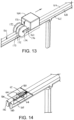
- FIG. 14 Yet another tray-charging or -powering arrangement is shown in FIG. 14 .
- the tray 180 has a single centrally located charging coil 62 connected in parallel with two tuning capacitors 64. Although two tuning capacitors 64 are shown, a single tuning capacitor could be used instead.
- a primary conductor loop is formed by a left conductor segment 182 in a left rail 184 connected to a right conductor segment 183 in a right rail 185.
- the endless primary conductor loop is tuned to resonance with one or more tuning capacitors (not shown) and is powered by an ac source (not shown).
- This version can be used with rails without lateral rail extensions.
- FIG. 7 One version of an electrical block diagram schematic of a conveyor as in FIG. 1 or FIG. 5 is shown in FIG. 7 .
- the tray controller 56 in this example is powered by either an external ac power source 82 or the battery 58. When the external source 82 is available, its power is inductively coupled to the tray from the primary conductive loop 78 to the secondary charging coil 62.
- the tuning capacitors 84, distributed along the length of the loop 78, and the tray tuning capacitor 64 tune the primary and secondary circuits to resonate at the frequency of the ac source 82 to maximize power transfer.
- the secondary ac voltage is converted to dc by a rectifier or ac-to-dc converter 86 whose output is diode-ORed with the battery voltage 92 through a diode 94 to produce a dc supply voltage 88 that powers the tray.
- a rectifier or ac-to-dc converter 86 whose output is diode-ORed with the battery voltage 92 through a diode 94 to produce a dc supply voltage 88 that powers the tray.
- the externally sourced voltage will exceed the battery voltage 92 and power the tray controller 56 and other active devices in the tray.
- the battery 58 switches in to power the tray when the externally sourced voltage drops below the battery voltage 92.
- the external voltage exceeds the battery voltage 92, it charges the battery 58 through a charging element 96.
- the diode-ORed arrangement constitutes a rudimentary switch that switches between external and battery power for the tray.
- One example of an alternative switch useful for switching from external power to battery power includes an electromechanical or an electronic switch that connects the tray's dc supply voltage 88 to the battery voltage 92 from the externally sourced dc voltage when the external power is too low.
- a low-voltage detector sensing the incoming ac voltage or its rectified dc voltage sends a low-voltage signal to the switch to switch to battery power.
- a series of magnetic field sensors 98 such as Hall-effect sensors positioned periodically along the length of the tray blade 42 ( FIG. 4 ), determine the position of the tray coils 54 relative to the magnetic-field positive and negative peaks.
- the sensor signals 99 are sent to the controller 56, which includes a commutator 100.
- the commutator 100 is a software routine that runs in program memory of the controller 56, e.g., a microcomputer or microcontroller.
- the commutator 100 generates three output signals 104, which are properly phased as determined by the sensor signals 99, to control the current through the three-phase forcer coils 54.
- the three output signals 104 are amplified by amplifiers 102 that supply the commutated current waveforms to the forcer coils 54 to drive the tray.
- the tray controller 56 in each tray communicates with a conveyor controller 106 external to the trays.
- a transmitter-receiver 108 on the tray circuit board 57 is linked wirelessly over antennas 110, 111 to an external transmitter-receiver 109 connected to the system controller 106.
- the system controller 106 sends command and data requests to the tray controllers 56 over the wireless link and receives data from the tray controllers.
- the tray antenna 110 is shown in FIG. 4 as a dipole embedded in the tray platform 38 along one end of the tray 36 as one example.
- a tray carriage 112 used to transfer trays from one conveyor segment to another is shown in FIG. 8 .
- the carriage 112 is the same as the trays described previously, but with a pair of passive transfer rails 114, 115 mounted on the top surface 116.
- the transfer rails 114, 115 have permanent-magnet arrays disposed along their lengths.
- the narrow slot 118 between the transfer rails 114, 115 extends in length perpendicular to the plane of the carriage blade 120.
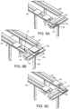
- FIGS. 9A-9C illustrate how the carriage 112 transfers trays from one conveyor segment 68 to another 68'.
- a tray 36 advancing along a first conveyor segment 68 at an end of a first conveyor run is received on the transfer rails 114, 115 of the carriage 112.
- the carriage 112 is supported on a carriage conveyor segment 122 extending perpendicular to the planes of the slots 72 in the first and second conveyor segments 68, 68'.
- the carriage conveyor segment 122 is below the level of the tray conveyor segments 68, 68' so that the transfer rails 114, 115 are at the same level as the tray conveyor rails 70, 71.
- the transfer rails 114, 115 and the transfer slot 118 can be aligned with the tray coils 70, 71 and the tray slot 72 on the first tray conveyor segment 68 to smoothly receive the tray 36 as in FIG. 9A .
- the carriage 112 energizes its drive coils and propels itself and the tray 36 laterally in a transverse direction 116 as in FIG. 9B along the carriage conveyor segment 122.
- the carriage conveyor segment 122 has permanent-magnet carriage rails 124, 125 and a carriage slot 126 like the tray conveyor segments.
- the carriage segment 122 has a shorter leg 118 than the tray conveyor segment to position the top surface 128 of the carriage segment 122 skewed perpendicular to and below the tops of 76, 77 of the conveyor segments 68, 68'.
- the carriage 112 stops, and the tray 36 energizes itself to advance off the transfer rails 114, 115 and onto the aligned conveyor segment rails 70, 71 on the second conveyor segment 68'.
- an endless tray conveyor is formed. The carriage 112 then translates back to the first conveyor segment 68 to receive the next tray.
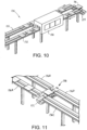
- a tray washer 130 is shown covering a portion of the return run 132 in an endless conveyor configuration 134 in FIG. 10 .
- a carriage conveyor segment 122 is shown at one end of the endless conveyor 134 for transferring trays 36 from a carryway run 133 to the return run 132.
- the tray washer 130 includes spray nozzles and brushes to clean, rinse, sanitize, and dry the trays 36.
- the carriage conveyor segment 122 can be used to transfer trays 36 between many conveyor sections 136A, 136B, 136C, 136D.
- the four tray conveyor sections are arranged parallel to each other with two on each side of a gap 138 across which the carriage 112 translates perpendicular to the tray conveyor sections 136A-D.
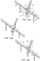
- the conveyor configuration of FIGS. 12A-12C has two tray conveyor segments 140A, 140B in line across a gap 142.
- a third tray conveyor segment 140C extends obliquely away from the gap 142.
- the obliquely oriented conveyor segment 140C constitutes a divert path for trays 36 away from a straight-through path on the in-line conveyor segment 140B.
- a diverter carriage segment 141 includes a diverter carriage 144 that resides in the gap 142.
- Diverter rails 146, 147 with embedded permanent-magnet arrays are selectively aligned with either the rails of the in-line tray conveyor segments 140A, 140B or with the oblique tray conveyor segment 140C.
- the diverter carriage 144 includes a post 148 extending downward from the rails 146, 147 to a diverter carriage platform 150, which is supported on a cylindrical diverter base 152.
- the base 152 houses a ring of permanent magnets that creates a magnetic field directed radially from the base's periphery.
- the diverter carriage platform 150 has side skirts 154 that extend downward around the periphery of the diverter base 152.
- Diverter carriage drive coils (not shown) in the skirts driven by a diverter controller (not shown) in the diverter carriage 144 produce an electromagnetic field that interacts with the permanent-magnet magnetic field of the base 152 to rotate the diverter carriage 144 between an in-line tray pass-through position as in FIGS.
- the diverter carriage segment 141 can be used to merge products from the tray segments 140B, 140C onto the tray segment 140A when the trays 36 advance opposite to the direction of the arrows in FIG. 12C .
- a rail scrubber 160 is shown in FIG. 13 cleaning a tray conveyor section 162.
- the scrubber 160 has a housing 164 covering water, cleanser, and sanitizer tanks (not shown).
- the housing 164 mounts on a base (not shown) such as a conveyor tray with a drive-coil blade that fits in the slot 166 between the two rails 168, 169 and propels the scrubber 160 along the conveyor section 162.
- One or more nozzles 170 spray the water, cleanser, or sanitizer onto the rails 168, 169.
- Outer rotary brushes 172 and an inner rotary brush 173 are mounted on an axle 174 retained at its ends by arms 176 attached to the scrubber housing 164.
- the outer rotary brushes 172 have bristles at least on an inner side to scrub the outer sides of the rails 168, 169.
- the inner brush 173 rides in the slot 166 and has bristles on both side to scrub the inside walls of the rails 168, 169.
Landscapes
- Engineering & Computer Science (AREA)
- Power Engineering (AREA)
- Physics & Mathematics (AREA)
- Electromagnetism (AREA)
- Chemical & Material Sciences (AREA)
- Combustion & Propulsion (AREA)
- Transportation (AREA)
- Mechanical Engineering (AREA)
- Non-Mechanical Conveyors (AREA)
- Linear Motors (AREA)
Description
- The invention relates generally to power-driven conveyors and more particularly to conveyors in which trays are driven independently by brushless dc motors.
- Conventional conveying systems, such as those conveying articles on flat belts, modular belts or chains, and powered or gravity rollers, provide many harbors for pathogens and other contaminants. Motors, gearboxes, roller bearings, shafts, pulleys, and sprockets can all collect food particles and grease and require regular cleaning. In food applications all the conveyor parts have to comply with demanding food-use standards. Furthermore, conventional conveyors require significant electrical infrastructure for power and control. Cable routing and connections add additional harbors for contaminants.
-
EP 0 241 875 A2 discloses a solid state commutated linear motor with an ironless multiphase armature which has a magnetic field array having periodic alternating polarity, an ironless multiphase armature, and a solid state commutating system for driving a moving element and positioning it with respect to a reference element. -
JP 2004 015894 A -
US 8 829 740 B2 discloses a sealed linear motor system including a sealed coil assembly having a plurality of coil windings within a base plate and comprising covers disposed about the base plate and coil windings to prevent moisture and/or chemical ingress into the base plate and the coil windings. - A conveyor according to the invention is described in the independent claim. Further aspects of the invention are described in the dependent claims.
-
-
FIG. 1 is an isometric view of a portion of a tray conveyor embodying features of the invention. -
FIG. 2 is an enlarged cross section of the tray conveyor viewed along lines II-II ofFIG. 1 . -
FIG. 3 is an enlarged cross section of the tray conveyor viewed along lines III-III ofFIG. 1 with the inside wall of a support rail cut away to reveal a permanent-magnet array. -
FIG. 4 is an isometric view of a tray usable in the conveyor ofFIG. 1 with the tray body shown in phantom lines. -
FIG. 5 is an isometric view of a portion of another version of a conveyor as inFIG. 1 with a conductor loop along both sides for inductively coupling power to the tray. -
FIG. 6 is an enlarged cross section of the conveyor ofFIG. 5 viewed along lines VI-VI ofFIG. 5 . -
FIG. 7 is a schematic block diagram of one version of an electrical system for a conveyor as inFIG. 5 orFIG. 1 . -
FIG. 8 is an isometric view of a tray carriage usable in a conveyor as inFIG. 1 orFIG. 5 . -
FIGS. 9A-9C are sequential isometric views of one end of a conveyor as inFIG. 5 using a tray carriage as inFIG. 8 to form an endless conveyor. -
FIG. 10 is an isometric view of a tray washer for a conveyor as inFIG. 1 orFIG. 5 . -
FIG. 11 is an isometric view of a tray carriage as inFIG. 8 used to transfer trays from one conveyor segment to others. -
FIGS. 12A-12C are sequential isometric views of a tray diverter section for a conveyor as inFIG. 1 orFIG. 5 . -
FIG. 13 is an isometric view of a rail scrubber on a conveyor as inFIG. 1 . -
FIG. 14 is an isometric view of a portion of another version of a conveyor as inFIG. 1 with a conductor loop shared by both sides for inductively coupling power to the tray over a single secondary coil in the tray. - A portion of one version of a conveyor embodying features of the invention is shown in
FIG. 1 . Theconveyor section 20 is constructed of a series oftray conveyor segments 22 connected end to end atbonded joints 24 for smooth transitions. As also shown inFIG. 2 , thetray conveyor segments 22 each comprise a pair of closely spacedrails rounded tops rail base 30 from which asingle leg 32 extends downward to mount to a floor. The tworails narrow slot 34. Atray 36 has aplatform 38 with a top article-supportingsurface 40 and anopposite bottom surface 41 supported on thetops rails blade 42 extends downward from thebottom surface 41 of thetray 36 into theslot 34. Thetray 36 shown in this example with a centrally locatedblade 42 forms a T in a vertical cross section. A linear array ofpermanent magnets 44 in eachrail slot 34 and thetray blade 42. The magnitude and direction of the static magnetic field vary periodically along the length of theslot 34. Forcer coils (not shown inFIG. 1 ) in thetray blade 42 produce a varying electromagnetic field that interacts with the magnetic field produced by the linear permanent-magnet arrays in the rail to create a force propelling thetray 36 along the conveyor in a conveyingdirection 46. - As shown in
FIG. 2 , theslot 34 above theleg 32 extends upward from a lowerblind end 48 formed by therail base 30 to a top opening 50 that widens at thetops rails slot 34 is open at both top and bottom. As shown inFIG. 3 , the linear array ofpermanent magnets 44 is embedded in therail 27 close to aninside wall 52 of the rail bounding theslot 34. To increase the intensity of the magnetic field in theslot 34, thepermanent magnets 44 are shown arranged to form a Halbach array. The static magnetic field traversing theslot 34 varies spatially in amplitude and direction in theconveying direction 46. - As shown in
FIG. 4 , a series offorcer drive coils 54 is housed in thetray blade 42. Thecoils 54 are arranged in an alternating three-phase pattern along the length of theblade 42. Atray controller 56 housed in thetray 36 electronically commutates the currents through the three-phase coils 54 to produce an electromagnetic field that travels along theblade 42 and interacts with the static magnetic field in the slot. Thecontroller 56 and auxiliary components are mounted on acircuit board 57. The cores of thecoils 54 are ironless to avoid attraction to the rail magnets and increased friction. Thedrive coils 54 thus form a brushless linear dc motor with the permanent-magnet arrays in the rails. The permanent magnet arrays form the motor's stator and the coactingtray coils 54 form the motor's forcer. - A
battery 58 consisting of one ormore cells 60 powers thecontroller 56 and provides the commutated currents to thecoils 54. Because the permanent magnets are in the rails and the trays are battery-powered, no wiring is needed in the tray conveyor segments. The tray segments are completely passive.Optional charging coils 62 in one or both sides of thetray 36 are available to recharge thebattery 58. Alternatively, thecharging coils 62 could be used to couple power to thetray 36 to power thecontroller 56 and theforcer coils 54. In that alternative mode of operation, in which the primary power is inductively coupled to thetray 36 through thecharging coils 62, thebattery 58 can be used as a secondary power source when external power is unavailable to the charging coils. So either thebattery 58 or thecharging coils 62 can serve as the in-tray power supply. When the primary external power source is active, thecharging coils 62 can trickle-charge thebattery 58.Tuning capacitors 64 connected in parallel with thecharging coils 62 are available to tune the charging-coil and capacitor circuit to the resonant frequency of the external charging waveform to increase the efficiency of the induced power transfer to thetray 36. As a third alternative, thebattery 58 could be non-rechargeable and serve as the exclusive power source. In that case thecharging coils 62 and thetuning capacitors 64 would not be necessary. If thebattery 58 is not rechargeable, it could be replaceable though an end cap (66,FIG. 2 ), or the entire tray could be disposable. - When the charging coils 62 are used either to recharge the
battery 58 or as part of the main power source, one or moreactive conveyor segments 68 as inFIGS. 5 and 6 are used. Two closely spaced rails 70, 71 define anarrow slot 72 to receive and guide theblade 42 of thetray 36. Therails lateral extensions flat tops tray 36.Primary conductor loops 78 powered by an ac power source (not shown) extend along the length of theactive conveyor section 68 in eachrail extension primary conductor loops 78 are mounted inE cores 80. The conductor loops are, for example, low-loss wire, such as Litz wire. Primary tuning capacitors (not shown) are distributed across the loop along the length of therails tray 36. The majority of the conveyor can be constructed ofactive segments 68 as inFIG. 5 or of a combination of active segments andpassive segments 22 as inFIG. 1 . For example, a conveyor having a main carryway run along which articles are conveyed and a return run could have passive segments on the carryway and active inductive-power-transfer segments on the return to recharge the batteries. In another alternative the active tray segment has a primary conductive loop on only one side. In that case a tray could be made with a secondary charging coil and tuning capacitor on only one side. - Yet another tray-charging or -powering arrangement is shown in
FIG. 14 . In this version the tray 180 has a single centrally located chargingcoil 62 connected in parallel with two tuningcapacitors 64. Although twotuning capacitors 64 are shown, a single tuning capacitor could be used instead. In this version a primary conductor loop is formed by aleft conductor segment 182 in aleft rail 184 connected to aright conductor segment 183 in aright rail 185. The endless primary conductor loop is tuned to resonance with one or more tuning capacitors (not shown) and is powered by an ac source (not shown). This version can be used with rails without lateral rail extensions. - One version of an electrical block diagram schematic of a conveyor as in
FIG. 1 orFIG. 5 is shown inFIG. 7 . Thetray controller 56 in this example is powered by either an externalac power source 82 or thebattery 58. When theexternal source 82 is available, its power is inductively coupled to the tray from the primaryconductive loop 78 to thesecondary charging coil 62. The tuningcapacitors 84, distributed along the length of theloop 78, and thetray tuning capacitor 64 tune the primary and secondary circuits to resonate at the frequency of theac source 82 to maximize power transfer. The secondary ac voltage is converted to dc by a rectifier or ac-to-dc converter 86 whose output is diode-ORed with thebattery voltage 92 through adiode 94 to produce adc supply voltage 88 that powers the tray. Normally, the externally sourced voltage will exceed thebattery voltage 92 and power thetray controller 56 and other active devices in the tray. Thebattery 58 switches in to power the tray when the externally sourced voltage drops below thebattery voltage 92. When the external voltage exceeds thebattery voltage 92, it charges thebattery 58 through a chargingelement 96. The diode-ORed arrangement constitutes a rudimentary switch that switches between external and battery power for the tray. One example of an alternative switch useful for switching from external power to battery power includes an electromechanical or an electronic switch that connects the tray'sdc supply voltage 88 to thebattery voltage 92 from the externally sourced dc voltage when the external power is too low. A low-voltage detector sensing the incoming ac voltage or its rectified dc voltage sends a low-voltage signal to the switch to switch to battery power. - A series of
magnetic field sensors 98, such as Hall-effect sensors positioned periodically along the length of the tray blade 42 (FIG. 4 ), determine the position of the tray coils 54 relative to the magnetic-field positive and negative peaks. The sensor signals 99 are sent to thecontroller 56, which includes acommutator 100. Thecommutator 100 is a software routine that runs in program memory of thecontroller 56, e.g., a microcomputer or microcontroller. Thecommutator 100 generates threeoutput signals 104, which are properly phased as determined by the sensor signals 99, to control the current through the three-phase forcer coils 54. The threeoutput signals 104 are amplified byamplifiers 102 that supply the commutated current waveforms to the forcer coils 54 to drive the tray. - The
tray controller 56 in each tray communicates with aconveyor controller 106 external to the trays. A transmitter-receiver 108 on thetray circuit board 57 is linked wirelessly overantennas 110, 111 to an external transmitter-receiver 109 connected to thesystem controller 106. Thesystem controller 106 sends command and data requests to thetray controllers 56 over the wireless link and receives data from the tray controllers. Thetray antenna 110 is shown inFIG. 4 as a dipole embedded in thetray platform 38 along one end of thetray 36 as one example. - A
tray carriage 112 used to transfer trays from one conveyor segment to another is shown inFIG. 8 . Thecarriage 112 is the same as the trays described previously, but with a pair ofpassive transfer rails top surface 116. Like the tray rails 26, 27 inFIG. 2 , the transfer rails 114, 115 have permanent-magnet arrays disposed along their lengths. Thenarrow slot 118 between the transfer rails 114, 115, extends in length perpendicular to the plane of thecarriage blade 120. -
FIGS. 9A-9C illustrate how thecarriage 112 transfers trays from oneconveyor segment 68 to another 68'. Atray 36 advancing along afirst conveyor segment 68 at an end of a first conveyor run is received on the transfer rails 114, 115 of thecarriage 112. Thecarriage 112 is supported on acarriage conveyor segment 122 extending perpendicular to the planes of theslots 72 in the first andsecond conveyor segments 68, 68'. Thecarriage conveyor segment 122 is below the level of thetray conveyor segments 68, 68' so that the transfer rails 114, 115 are at the same level as the tray conveyor rails 70, 71. In that way the transfer rails 114, 115 and thetransfer slot 118 can be aligned with the tray coils 70, 71 and thetray slot 72 on the firsttray conveyor segment 68 to smoothly receive thetray 36 as inFIG. 9A . Once thetray 36 resides completely on thecarriage 112, it stops itself. Thecarriage 112 energizes its drive coils and propels itself and thetray 36 laterally in atransverse direction 116 as inFIG. 9B along thecarriage conveyor segment 122. Thecarriage conveyor segment 122 has permanent-magnet carriage rails 124, 125 and acarriage slot 126 like the tray conveyor segments. Thecarriage segment 122 has ashorter leg 118 than the tray conveyor segment to position thetop surface 128 of thecarriage segment 122 skewed perpendicular to and below the tops of 76, 77 of theconveyor segments 68, 68'. When thecarriage 112 reaches a position with itstransfer rails FIG. 9C , thecarriage 112 stops, and thetray 36 energizes itself to advance off the transfer rails 114, 115 and onto the aligned conveyor segment rails 70, 71 on the second conveyor segment 68'. With an identical carriage conveyor segment at the opposite end of the two tray conveyor sections, an endless tray conveyor is formed. Thecarriage 112 then translates back to thefirst conveyor segment 68 to receive the next tray. - A
tray washer 130 is shown covering a portion of thereturn run 132 in anendless conveyor configuration 134 inFIG. 10 . Acarriage conveyor segment 122 is shown at one end of theendless conveyor 134 for transferringtrays 36 from acarryway run 133 to thereturn run 132. Thetray washer 130 includes spray nozzles and brushes to clean, rinse, sanitize, and dry thetrays 36. - As shown in
FIG. 11 , thecarriage conveyor segment 122 can be used to transfertrays 36 betweenmany conveyor sections gap 138 across which thecarriage 112 translates perpendicular to thetray conveyor sections 136A-D. - The conveyor configuration of
FIGS. 12A-12C has twotray conveyor segments gap 142. A thirdtray conveyor segment 140C extends obliquely away from thegap 142. The obliquely orientedconveyor segment 140C constitutes a divert path fortrays 36 away from a straight-through path on the in-line conveyor segment 140B. Adiverter carriage segment 141 includes adiverter carriage 144 that resides in thegap 142. Diverter rails 146, 147 with embedded permanent-magnet arrays are selectively aligned with either the rails of the in-linetray conveyor segments tray conveyor segment 140C. Thediverter carriage 144 includes apost 148 extending downward from therails diverter carriage platform 150, which is supported on acylindrical diverter base 152. The base 152 houses a ring of permanent magnets that creates a magnetic field directed radially from the base's periphery. Thediverter carriage platform 150 hasside skirts 154 that extend downward around the periphery of thediverter base 152. Diverter carriage drive coils (not shown) in the skirts driven by a diverter controller (not shown) in thediverter carriage 144 produce an electromagnetic field that interacts with the permanent-magnet magnetic field of the base 152 to rotate thediverter carriage 144 between an in-line tray pass-through position as inFIGS. 12A and 12B and an oblique tray divert position as inFIG. 12C . Thediverter carriage segment 141 can be used to merge products from thetray segments tray segment 140A when thetrays 36 advance opposite to the direction of the arrows inFIG. 12C . - A
rail scrubber 160 is shown inFIG. 13 cleaning atray conveyor section 162. Thescrubber 160 has ahousing 164 covering water, cleanser, and sanitizer tanks (not shown). Thehousing 164 mounts on a base (not shown) such as a conveyor tray with a drive-coil blade that fits in theslot 166 between the tworails scrubber 160 along theconveyor section 162. One ormore nozzles 170 spray the water, cleanser, or sanitizer onto therails rotary brush 173 are mounted on anaxle 174 retained at its ends byarms 176 attached to thescrubber housing 164. The outer rotary brushes 172 have bristles at least on an inner side to scrub the outer sides of therails inner brush 173 rides in theslot 166 and has bristles on both side to scrub the inside walls of therails
Claims (10)
- A conveyor comprising:a rail (26, 27) having an array of permanent magnets (44) embedded in and extending along the length of the rail (26, 27) to form a permanent-magnet stator creating a magnetic field;a tray (36) supported on the rail (26, 27) and having a top article-supporting surface (40) and having a series of commutated drive coils (54) as a forcer coacting with the permanent-magnet stator to form a brushless linear dc motor to propel the tray (36) along the rail (26, 27);a tray conveyor segment (22) extending from a first end to a second end in a conveying direction (46) and including:a pair of the rails (26, 27) closely spaced and separated by a slot (34) and having tops (28, 29), each of the rails (26, 27) including such an array of permanent magnets (44) creating a magnetic field across the slot (34);wherein the tray (36) includes:a platform (38) forming the top article-supporting surface (40) and a bottom surface (41) supported on the tops (28, 29) of the rails (26, 27);a blade (42) extending downward from the bottom surface (41) and in the conveying direction (46) to ride in the slot (34) and housing the series of commutated drive coils (54);a tray controller (56) driving the drive coils (54) to produce a traveling electromagnetic wave that interacts with the magnetic field to propel the tray (36) in the conveying direction (46);wherein the slot (34) widens at the tops (28, 29) of the rails (26, 27) and the tops (28, 29) of the rails (26, 27) are convexly curved.
- A conveyor as in claim 1 wherein a) the drive coils (54) are three-phase coils, the tray controller (56) commutates current through the three-phase coils (54) to form the brushless linear dc motor with the permanent-magnet arrays in the rails (26, 27); or b) the drive coils (54) are three-phase coils, the tray controller (56) commutates current through the three-phase coils to form the brushless linear dc motor with the permanent-magnet arrays in the rails (26, 27) and wherein the tray (36) includes sensors in the blade (42) sensing the magnitude of the magnetic field and sending sensor signals to the tray controller (56) to commutate the current.
- A conveyor as in claim 1 wherein the drive coils (54) have ironless cores.
- A conveyor as in claim 1 further comprising a primary conductor loop (78) external to the tray (36) and extending in the conveying direction (46) along a length of the rails (26, 27) and wherein the tray (36) further includes a secondary coil (62) inductively coupled to the primary conductor loop (78) to supply power to the tray (36) while on the length of the rails (26, 27).
- A conveyor as in claim 4 wherein the tray (36) includes a battery (58) to power the tray controller (56) and the series of drive coils (54) and wherein the battery (58) is recharged through the secondary coil (62).
- A conveyor as in claim 1 further comprising a rail base (30) joining the rails (26, 27) and forming a closed end of the slot (34) and a series of single legs (32) extending downward from the base (30) to mount the conveyor to a floor.
- A conveyor as in claim 1 further comprising:a carriage conveyor segment (122) like the tray conveyor segment but arranged with carriage rails (124, 125) and a carriage slot (126) perpendicular to and skewed below the rails and slot of the tray conveyor segment;a carriage (112) including:a carriage platform supported on the tops of the carriage rails (124, 125);a carriage blade (120) extending downward from the carriage platform to ride in the carriage slot (126);a series of carriage drive coils in the carriage blade;a pair of closely spaced transfer rails (114, 115) separated by a transfer slot (118) and extending up from the carriage platform to tops level with the tops of the rails in the tray conveyor segment to receive a tray from or discharge a tray to the tray conveyor segment;a carriage controller driving the carriage drive coils to produce a traveling electromagnetic wave that interacts with the magnetic field in the carriage slot (126) to propel the carriage (112) along the carriage conveyor segment (122) in a transverse direction (116) from a first position in which the transfer rails (114, 115) are aligned with the rails of the tray conveyor segment to a second position in which the transfer rails are transversely offset from the rails of the tray conveyor segment.
- A conveyor as in claim 1 further comprising:a plurality of the tray conveyor segments (140A, 140B, 140C) in which a first one of the tray conveyor segments (140C) extends obliquely from the first end of a second one of the tray conveyor segments across a gap (142);a diverter carriage segment (141) having a cylindrical diverter base (152) housing a ring of permanent magnets creating a magnetic field about the periphery of the diverter base;a diverter carriage (144) including:a diverter carriage platform (150) supported on the diverter base (152) and having side skirts (154) extending downward around the periphery of the diverter base (152);a series of diverter carriage drive coils in each of the side skirts (154);a pair of closely spaced diverter rails (146, 147) separated by a diverter slot and extending up from the diverter carriage platform to tops level with the tops of the rails in the first and second tray conveyor segments (140A, 140B, 140C) to receive a tray from or discharge a tray to the tray conveyor segment;a diverter carriage controller driving the diverter carriage drive coils to produce a traveling electromagnetic wave that interacts with the magnetic field around the diverter base (152) to rotate the diverter from a first position in which the diverter rails are aligned with the rails of the first one of the tray conveyor segments to a second position in which the diverter rails are aligned with the rails of the second one of the tray conveyor segments.
- A conveyor as in claim 1 further comprising a scrubber (160) including:a blade that rides in the slot (166);a series of scrubber coils housed in the blade;a scrubber controller driving the scrubber coils to produce a traveling electromagnetic wave that interacts with the magnetic field to propel the tray along the tray conveyor segment;a supply of cleansing solution;a spray nozzle (170) spraying the cleansing solution onto the rails.
- A conveyor as in claim 9 wherein the scrubber further includes rotary scrub brushes (172, 173) that ride in the slot (166) and along the outer sides of the rails to scrub the rails.
Applications Claiming Priority (2)
| Application Number | Priority Date | Filing Date | Title |
|---|---|---|---|
| US201762500267P | 2017-05-02 | 2017-05-02 | |
| PCT/US2018/025779 WO2018204006A1 (en) | 2017-05-02 | 2018-04-03 | Tray conveyor driven by brushless dc motor |
Publications (3)
| Publication Number | Publication Date |
|---|---|
| EP3619149A1 EP3619149A1 (en) | 2020-03-11 |
| EP3619149A4 EP3619149A4 (en) | 2021-01-13 |
| EP3619149B1 true EP3619149B1 (en) | 2025-07-09 |
Family
ID=64016208
Family Applications (1)
| Application Number | Title | Priority Date | Filing Date |
|---|---|---|---|
| EP18794640.5A Active EP3619149B1 (en) | 2017-05-02 | 2018-04-03 | Tray conveyor driven by brushless dc motor |
Country Status (6)
| Country | Link |
|---|---|
| US (1) | US10994953B2 (en) |
| EP (1) | EP3619149B1 (en) |
| JP (1) | JP7177785B2 (en) |
| CN (1) | CN110612260B (en) |
| ES (1) | ES3035815T3 (en) |
| WO (1) | WO2018204006A1 (en) |
Families Citing this family (6)
| Publication number | Priority date | Publication date | Assignee | Title |
|---|---|---|---|---|
| US10965201B2 (en) * | 2017-09-25 | 2021-03-30 | Canon Kabushiki Kaisha | Transport system, processing system and manufacturing method of article |
| DE202020102692U1 (en) * | 2020-05-13 | 2020-06-05 | Markus Pfuderer | Modular transfer system |
| CN113277279A (en) * | 2021-06-21 | 2021-08-20 | 大工科技(上海)有限公司 | Stage scene integrated control system based on flexible intelligent transmission platform |
| BR102021018108A2 (en) | 2021-09-13 | 2023-03-28 | Freed Participaçoes S/A | CONVEYOR BELT DRIVED BY LINEAR INDUCTION MOTOR WITH DOUBLE-SIDED PRIMARY AND LONG SECTIONED SECONDARY |
| CN116393879B (en) * | 2023-06-02 | 2023-09-08 | 西安热工研究院有限公司 | Automatic welding equipment and method for high-altitude pipelines |
| CN222138077U (en) * | 2024-09-24 | 2024-12-10 | 宁德时代新能源科技股份有限公司 | Battery conveying device and battery drying system |
Citations (6)
| Publication number | Priority date | Publication date | Assignee | Title |
|---|---|---|---|---|
| EP0241875A2 (en) * | 1986-04-11 | 1987-10-21 | Compact Spindle Bearing Corporation | Improved solid state commutated linear motor with an ironless multiphase armature |
| JP2004015894A (en) * | 2002-06-05 | 2004-01-15 | Yaskawa Electric Corp | Linear motor |
| EP1956705A1 (en) * | 2005-11-30 | 2008-08-13 | THK Co., Ltd. | Wireless actuator |
| US20130187573A1 (en) * | 2010-09-30 | 2013-07-25 | Thk Co., Ltd. | Control apparatus for linear motor, and linear motor apparatus |
| WO2014059134A1 (en) * | 2012-10-11 | 2014-04-17 | Siemens Healthcare Diagnostics Inc. | Automation maintenance carrier |
| US8829740B2 (en) * | 2010-05-27 | 2014-09-09 | Rockwell Automation Technologies, Inc. | Sealed linear motor system |
Family Cites Families (24)
| Publication number | Priority date | Publication date | Assignee | Title |
|---|---|---|---|---|
| US3625181A (en) | 1969-10-27 | 1971-12-07 | Arthur J Weaver | Apparatus for cleaning and oiling paving forms |
| US3788447A (en) * | 1972-07-03 | 1974-01-29 | Fmc Corp | Linear motor conveyor |
| US3786779A (en) | 1972-09-13 | 1974-01-22 | Klenco Corp | Overhead rail cleaner and oiler |
| US4092554A (en) * | 1977-05-19 | 1978-05-30 | The Raymond Lee Organization, Inc. | Linear electric generating system |
| JPS60229603A (en) | 1984-04-26 | 1985-11-15 | Toshiba Corp | Conveying apparatus |
| NL8902586A (en) * | 1989-10-19 | 1991-05-16 | Vanderlande Ind Nederland | TRANSPORT DEVICE. |
| JPH0432478U (en) * | 1990-07-16 | 1992-03-17 | ||
| GB9419734D0 (en) * | 1994-09-30 | 1994-11-16 | Linear Drives Ltd | Linear motor for extended travel |
| JP3446563B2 (en) * | 1997-10-23 | 2003-09-16 | 日立金属株式会社 | Linear motor |
| US6279728B1 (en) | 1998-07-20 | 2001-08-28 | Norbert G Jung | Electro-magnetic conveyor |
| TWI248718B (en) | 1999-09-02 | 2006-02-01 | Koninkl Philips Electronics Nv | Displacement device |
| JP3755366B2 (en) | 2000-01-19 | 2006-03-15 | 株式会社ダイフク | Load handling equipment |
| US6629503B2 (en) * | 2001-06-29 | 2003-10-07 | The Regents Of The University Of California | Inductrack configuration |
| US6684794B2 (en) | 2002-05-07 | 2004-02-03 | Magtube, Inc. | Magnetically levitated transportation system and method |
| KR20070099609A (en) | 2005-01-17 | 2007-10-09 | 코닌클리케 필립스 일렉트로닉스 엔.브이. | Mobile devices |
| WO2009083889A1 (en) | 2007-12-28 | 2009-07-09 | Koninklijke Philips Electronics N.V. | Contactless lifting of an object by an inverted planar motor |
| JP5480597B2 (en) * | 2009-11-04 | 2014-04-23 | ヤマハ発動機株式会社 | Linear conveyor |
| DE102012220008B4 (en) * | 2012-11-02 | 2023-06-01 | Syntegon Technology Gmbh | Transport device with controllable conveying element |
| JP6067421B2 (en) | 2013-03-01 | 2017-01-25 | 住友重機械工業株式会社 | Linear motor |
| CN105813886B (en) | 2013-09-21 | 2018-04-03 | 麦克纳莫绅有限公司 | Transported for packing with the linear electric machine of other purposes |
| JP5855631B2 (en) * | 2013-12-17 | 2016-02-09 | ファナック株式会社 | Machine tool having linear drive device with linear motor |
| JP6313642B2 (en) * | 2014-04-18 | 2018-04-18 | キヤノン株式会社 | Linear motor control device and linear motor control system |
| DE102014225171A1 (en) | 2014-12-08 | 2016-06-09 | Robert Bosch Gmbh | Securing system for an arrangement for moving transport bodies |
| US9611107B2 (en) | 2014-12-08 | 2017-04-04 | Rockwell Automation Technologies, Inc. | Linear drive transport system and method |
-
2018
- 2018-04-03 US US16/609,694 patent/US10994953B2/en active Active
- 2018-04-03 WO PCT/US2018/025779 patent/WO2018204006A1/en not_active Ceased
- 2018-04-03 CN CN201880028303.0A patent/CN110612260B/en active Active
- 2018-04-03 EP EP18794640.5A patent/EP3619149B1/en active Active
- 2018-04-03 ES ES18794640T patent/ES3035815T3/en active Active
- 2018-04-03 JP JP2019555181A patent/JP7177785B2/en active Active
Patent Citations (6)
| Publication number | Priority date | Publication date | Assignee | Title |
|---|---|---|---|---|
| EP0241875A2 (en) * | 1986-04-11 | 1987-10-21 | Compact Spindle Bearing Corporation | Improved solid state commutated linear motor with an ironless multiphase armature |
| JP2004015894A (en) * | 2002-06-05 | 2004-01-15 | Yaskawa Electric Corp | Linear motor |
| EP1956705A1 (en) * | 2005-11-30 | 2008-08-13 | THK Co., Ltd. | Wireless actuator |
| US8829740B2 (en) * | 2010-05-27 | 2014-09-09 | Rockwell Automation Technologies, Inc. | Sealed linear motor system |
| US20130187573A1 (en) * | 2010-09-30 | 2013-07-25 | Thk Co., Ltd. | Control apparatus for linear motor, and linear motor apparatus |
| WO2014059134A1 (en) * | 2012-10-11 | 2014-04-17 | Siemens Healthcare Diagnostics Inc. | Automation maintenance carrier |
Also Published As
| Publication number | Publication date |
|---|---|
| EP3619149A4 (en) | 2021-01-13 |
| CN110612260B (en) | 2021-12-24 |
| CN110612260A (en) | 2019-12-24 |
| JP7177785B2 (en) | 2022-11-24 |
| US10994953B2 (en) | 2021-05-04 |
| JP2020519220A (en) | 2020-06-25 |
| ES3035815T3 (en) | 2025-09-09 |
| US20200198905A1 (en) | 2020-06-25 |
| WO2018204006A1 (en) | 2018-11-08 |
| EP3619149A1 (en) | 2020-03-11 |
| BR112019021151A2 (en) | 2020-05-12 |
Similar Documents
| Publication | Publication Date | Title |
|---|---|---|
| EP3619149B1 (en) | Tray conveyor driven by brushless dc motor | |
| US11715977B2 (en) | Method and system for contactless power transfer in a linear drive system | |
| JP7432627B2 (en) | linear motor conveyor system | |
| US11303242B2 (en) | Method and apparatus for wireless power transfer to an independent moving cart | |
| US20210099119A1 (en) | System and Method for Wireless Power Transfer in a Linear Cart System | |
| JP7443428B2 (en) | monorail tray conveyor | |
| US8720668B2 (en) | Conveyor belt apparatus including magnetically actuated rollers | |
| EP3461677A1 (en) | Mid-bus voltage generation via idle phases in a linear motor track system | |
| CN117595524A (en) | System and method for online wireless energy transfer and sensing in a self-contained cart system | |
| AU2018331269B2 (en) | Monorail tray conveyor with passive guide rails | |
| BR112019021151B1 (en) | CONVEYOR |
Legal Events
| Date | Code | Title | Description |
|---|---|---|---|
| STAA | Information on the status of an ep patent application or granted ep patent |
Free format text: STATUS: THE INTERNATIONAL PUBLICATION HAS BEEN MADE |
|
| PUAI | Public reference made under article 153(3) epc to a published international application that has entered the european phase |
Free format text: ORIGINAL CODE: 0009012 |
|
| STAA | Information on the status of an ep patent application or granted ep patent |
Free format text: STATUS: REQUEST FOR EXAMINATION WAS MADE |
|
| 17P | Request for examination filed |
Effective date: 20191017 |
|
| AK | Designated contracting states |
Kind code of ref document: A1 Designated state(s): AL AT BE BG CH CY CZ DE DK EE ES FI FR GB GR HR HU IE IS IT LI LT LU LV MC MK MT NL NO PL PT RO RS SE SI SK SM TR |
|
| AX | Request for extension of the european patent |
Extension state: BA ME |
|
| DAV | Request for validation of the european patent (deleted) | ||
| DAX | Request for extension of the european patent (deleted) | ||
| A4 | Supplementary search report drawn up and despatched |
Effective date: 20201210 |
|
| RIC1 | Information provided on ipc code assigned before grant |
Ipc: H02K 11/00 20160101ALI20201204BHEP Ipc: H02K 29/08 20060101ALI20201204BHEP Ipc: B65G 54/02 20060101AFI20201204BHEP Ipc: H02K 3/47 20060101ALI20201204BHEP Ipc: B60L 13/03 20060101ALI20201204BHEP Ipc: H02K 41/03 20060101ALI20201204BHEP Ipc: B65G 47/64 20060101ALN20201204BHEP |
|
| STAA | Information on the status of an ep patent application or granted ep patent |
Free format text: STATUS: EXAMINATION IS IN PROGRESS |
|
| 17Q | First examination report despatched |
Effective date: 20231114 |
|
| GRAP | Despatch of communication of intention to grant a patent |
Free format text: ORIGINAL CODE: EPIDOSNIGR1 |
|
| STAA | Information on the status of an ep patent application or granted ep patent |
Free format text: STATUS: GRANT OF PATENT IS INTENDED |
|
| RIC1 | Information provided on ipc code assigned before grant |
Ipc: B65G 47/64 20060101ALN20241231BHEP Ipc: B60L 13/03 20060101ALI20241231BHEP Ipc: H02K 11/00 20160101ALI20241231BHEP Ipc: H02K 29/08 20060101ALI20241231BHEP Ipc: H02K 3/47 20060101ALI20241231BHEP Ipc: H02K 41/03 20060101ALI20241231BHEP Ipc: B65G 54/02 20060101AFI20241231BHEP |
|
| INTG | Intention to grant announced |
Effective date: 20250130 |
|
| GRAS | Grant fee paid |
Free format text: ORIGINAL CODE: EPIDOSNIGR3 |
|
| GRAA | (expected) grant |
Free format text: ORIGINAL CODE: 0009210 |
|
| STAA | Information on the status of an ep patent application or granted ep patent |
Free format text: STATUS: THE PATENT HAS BEEN GRANTED |
|
| P01 | Opt-out of the competence of the unified patent court (upc) registered |
Free format text: CASE NUMBER: APP_20996/2025 Effective date: 20250502 |
|
| AK | Designated contracting states |
Kind code of ref document: B1 Designated state(s): AL AT BE BG CH CY CZ DE DK EE ES FI FR GB GR HR HU IE IS IT LI LT LU LV MC MK MT NL NO PL PT RO RS SE SI SK SM TR |
|
| REG | Reference to a national code |
Ref country code: GB Ref legal event code: FG4D |
|
| REG | Reference to a national code |
Ref country code: CH Ref legal event code: EP |
|
| REG | Reference to a national code |
Ref country code: NL Ref legal event code: FP Ref country code: IE Ref legal event code: FG4D |
|
| REG | Reference to a national code |
Ref country code: DE Ref legal event code: R096 Ref document number: 602018083437 Country of ref document: DE |
|
| REG | Reference to a national code |
Ref country code: ES Ref legal event code: FG2A Ref document number: 3035815 Country of ref document: ES Kind code of ref document: T3 Effective date: 20250909 |
|
| PG25 | Lapsed in a contracting state [announced via postgrant information from national office to epo] |
Ref country code: PT Free format text: LAPSE BECAUSE OF FAILURE TO SUBMIT A TRANSLATION OF THE DESCRIPTION OR TO PAY THE FEE WITHIN THE PRESCRIBED TIME-LIMIT Effective date: 20251110 |
|
| REG | Reference to a national code |
Ref country code: AT Ref legal event code: MK05 Ref document number: 1811699 Country of ref document: AT Kind code of ref document: T Effective date: 20250709 |
|
| PG25 | Lapsed in a contracting state [announced via postgrant information from national office to epo] |
Ref country code: IS Free format text: LAPSE BECAUSE OF FAILURE TO SUBMIT A TRANSLATION OF THE DESCRIPTION OR TO PAY THE FEE WITHIN THE PRESCRIBED TIME-LIMIT Effective date: 20251109 |
|
| PG25 | Lapsed in a contracting state [announced via postgrant information from national office to epo] |
Ref country code: NO Free format text: LAPSE BECAUSE OF FAILURE TO SUBMIT A TRANSLATION OF THE DESCRIPTION OR TO PAY THE FEE WITHIN THE PRESCRIBED TIME-LIMIT Effective date: 20251009 |
|
| REG | Reference to a national code |
Ref country code: LT Ref legal event code: MG9D |
|
| PG25 | Lapsed in a contracting state [announced via postgrant information from national office to epo] |
Ref country code: AT Free format text: LAPSE BECAUSE OF FAILURE TO SUBMIT A TRANSLATION OF THE DESCRIPTION OR TO PAY THE FEE WITHIN THE PRESCRIBED TIME-LIMIT Effective date: 20250709 |
|
| PG25 | Lapsed in a contracting state [announced via postgrant information from national office to epo] |
Ref country code: FI Free format text: LAPSE BECAUSE OF FAILURE TO SUBMIT A TRANSLATION OF THE DESCRIPTION OR TO PAY THE FEE WITHIN THE PRESCRIBED TIME-LIMIT Effective date: 20250709 |
|
| PG25 | Lapsed in a contracting state [announced via postgrant information from national office to epo] |
Ref country code: HR Free format text: LAPSE BECAUSE OF FAILURE TO SUBMIT A TRANSLATION OF THE DESCRIPTION OR TO PAY THE FEE WITHIN THE PRESCRIBED TIME-LIMIT Effective date: 20250709 |
|
| PG25 | Lapsed in a contracting state [announced via postgrant information from national office to epo] |
Ref country code: GR Free format text: LAPSE BECAUSE OF FAILURE TO SUBMIT A TRANSLATION OF THE DESCRIPTION OR TO PAY THE FEE WITHIN THE PRESCRIBED TIME-LIMIT Effective date: 20251010 |
|
| PG25 | Lapsed in a contracting state [announced via postgrant information from national office to epo] |
Ref country code: SE Free format text: LAPSE BECAUSE OF FAILURE TO SUBMIT A TRANSLATION OF THE DESCRIPTION OR TO PAY THE FEE WITHIN THE PRESCRIBED TIME-LIMIT Effective date: 20250709 |
|
| PG25 | Lapsed in a contracting state [announced via postgrant information from national office to epo] |
Ref country code: LV Free format text: LAPSE BECAUSE OF FAILURE TO SUBMIT A TRANSLATION OF THE DESCRIPTION OR TO PAY THE FEE WITHIN THE PRESCRIBED TIME-LIMIT Effective date: 20250709 |
|
| PG25 | Lapsed in a contracting state [announced via postgrant information from national office to epo] |
Ref country code: BG Free format text: LAPSE BECAUSE OF FAILURE TO SUBMIT A TRANSLATION OF THE DESCRIPTION OR TO PAY THE FEE WITHIN THE PRESCRIBED TIME-LIMIT Effective date: 20250709 Ref country code: PL Free format text: LAPSE BECAUSE OF FAILURE TO SUBMIT A TRANSLATION OF THE DESCRIPTION OR TO PAY THE FEE WITHIN THE PRESCRIBED TIME-LIMIT Effective date: 20250709 |
|
| PG25 | Lapsed in a contracting state [announced via postgrant information from national office to epo] |
Ref country code: RS Free format text: LAPSE BECAUSE OF FAILURE TO SUBMIT A TRANSLATION OF THE DESCRIPTION OR TO PAY THE FEE WITHIN THE PRESCRIBED TIME-LIMIT Effective date: 20251009 |
|
| PG25 | Lapsed in a contracting state [announced via postgrant information from national office to epo] |
Ref country code: SM Free format text: LAPSE BECAUSE OF FAILURE TO SUBMIT A TRANSLATION OF THE DESCRIPTION OR TO PAY THE FEE WITHIN THE PRESCRIBED TIME-LIMIT Effective date: 20250709 |
|
| PGFP | Annual fee paid to national office [announced via postgrant information from national office to epo] |
Ref country code: GB Payment date: 20260320 Year of fee payment: 9 |
|
| PG25 | Lapsed in a contracting state [announced via postgrant information from national office to epo] |
Ref country code: DK Free format text: LAPSE BECAUSE OF FAILURE TO SUBMIT A TRANSLATION OF THE DESCRIPTION OR TO PAY THE FEE WITHIN THE PRESCRIBED TIME-LIMIT Effective date: 20250709 |
|
| PGFP | Annual fee paid to national office [announced via postgrant information from national office to epo] |
Ref country code: NL Payment date: 20260323 Year of fee payment: 9 |
|
| PGFP | Annual fee paid to national office [announced via postgrant information from national office to epo] |
Ref country code: FR Payment date: 20260317 Year of fee payment: 9 |
|
| PG25 | Lapsed in a contracting state [announced via postgrant information from national office to epo] |
Ref country code: CZ Free format text: LAPSE BECAUSE OF FAILURE TO SUBMIT A TRANSLATION OF THE DESCRIPTION OR TO PAY THE FEE WITHIN THE PRESCRIBED TIME-LIMIT Effective date: 20250709 |
|
| PG25 | Lapsed in a contracting state [announced via postgrant information from national office to epo] |
Ref country code: EE Free format text: LAPSE BECAUSE OF FAILURE TO SUBMIT A TRANSLATION OF THE DESCRIPTION OR TO PAY THE FEE WITHIN THE PRESCRIBED TIME-LIMIT Effective date: 20250709 Ref country code: SK Free format text: LAPSE BECAUSE OF FAILURE TO SUBMIT A TRANSLATION OF THE DESCRIPTION OR TO PAY THE FEE WITHIN THE PRESCRIBED TIME-LIMIT Effective date: 20250709 |