TECHNICAL FIELD
-
The present disclosure relates to the technical field of communication, and more particularly to a wireless communication device and a method for switching an antenna.
BACKGROUND
-
Due to the relatively small size of a mobile phone, how and on which portion the user holds the mobile phone will have a significant impact on the performance of the antenna. In some cases, there may be problems with the degradation of antenna performance that affect the quality of mobile communication.
SUMMARY
-
Embodiments of the present disclosure provide a wireless communication device and a method for switching an antenna. The technical solution is as follows.
-
According to a first aspect of the embodiments of the present disclosure, there is provided a method for switching an antenna, which is applied to a wireless communication device including a first antenna in an operation state and a second antenna in a standby state.
-
The method for switching an antenna includes:
- detecting a performance parameter of the first antenna, the performance parameter including at least one of strength of a received signal and sensitivity; and
- when the performance parameter of the first antenna is lower than a preset threshold, switching the second antenna to the operation state, and switching the first antenna to the standby state.
-
The technical solution provided by the present disclosure is applied to a wireless communication device which includes a first antenna and a second antenna. While the first antenna is in the operation state, the second antenna is in the standby state, and when the performance of the first antenna has been degraded to a certain extent, the second antenna is switched to the operation state and the first antenna is switched to the standby state. Thereby it can improve the communication quality of the mobile phone by enabling the standby antenna when the performance of the antenna in the operation state has been degraded.
-
In an embodiment, the method for switching an antenna further includes: detecting an operation posture of the wireless communication device; and
detecting a performance parameter of the first antenna including: detecting the performance parameter of the first antenna when it is determined that the operation posture of the wireless communication device has been changed.
-
In an embodiment, the operation state of the first antenna is a primary operation state; and
when the performance parameter of the first antenna is lower than a preset threshold, switching the second antenna to the operation state including:
when the performance parameter of the first antenna is lower than a first preset threshold, switching the second antenna to the primary operation state.
-
In an embodiment, the wireless communication device further includes a third antenna, and the operation state of the third antenna is an auxiliary operation state, and the method for switching an antenna further includes:
when the performance parameter of the third antenna is lower than a second preset threshold, switching the third antenna to the standby state, and switching the first antenna to the auxiliary operation state.
-
In an embodiment, the operation state of the first antenna is an auxiliary operation state, and the wireless communication device further includes a third antenna, and the operation state of the third antenna is a primary operation state; and
when the performance parameter of the first antenna is lower than a preset threshold, switching the second antenna to the operation state including:
when the performance parameter of the third antenna is not lower than a first preset threshold, and the performance parameter of the first antenna is lower than a second preset threshold, switching the second antenna to the auxiliary operation state.
-
According to a second aspect of the embodiments of the present disclosure, there is provided a wireless communication device, including:
- a first antenna in an operation state and a second antenna in a standby state,
- a performance detecting module configured to detect a performance parameter of the first antenna, the performance parameter including at least one of strength of a received signal and sensitivity; and
- a switching module configured to, when the performance parameter of the first antenna is lower than a preset threshold, switch the second antenna to the operation state, and switch the first antenna to the standby state.
-
In an embodiment, the wireless communication device further includes: a posture detecting module configured to detect an operation posture of the wireless communication device;
wherein the performance detecting module includes a triggering sub-module configured to detect the performance parameter of the first antenna when it is determined that the operation posture of the wireless communication device has been changed.
-
In an embodiment, the operation state of the first antenna is a primary operation state; and
the switching module includes a primary switching sub-module configured to, when the performance parameter of the first antenna is lower than a first preset threshold, switch the second antenna to the primary operation state.
-
In an embodiment, the wireless communication device further includes a third antenna, wherein the operation state of the third antenna is an auxiliary operation state, and
the switching module includes a supplementary switching sub-module configured to, when the performance parameter of the third antenna is lower than a second preset threshold, switch the third antenna to the standby state, and switch the first antenna to the auxiliary operation state.
-
In an embodiment, the operation state of the first antenna is an auxiliary operation state, the wireless communication device further includes a third antenna, and the operation state of the third antenna is a primary operation state; and
the switching module includes an auxiliary switching sub-module configured to, when the performance parameter of the third antenna is not lower than a first preset threshold, and the performance parameter of the first antenna is lower than a second preset threshold, switch the second antenna to the auxiliary operation state.
-
According to a third aspect of the embodiments of the present disclosure, there is provided a wireless communication device, including:
- a first antenna in an operation state and a second antenna in a standby state,
- a processor; and
- a memory for storing instructions executable by the processor,
- wherein the processor is configured to:
- detect a performance parameter of the first antenna, the performance parameter including at least one of strength of a received signal and sensitivity; and
- when the performance parameter of the first antenna is lower than a preset threshold, switch the second antenna to the operation state, and switch the first antenna to the standby state.
-
According to a fourth aspect of the embodiments of the present disclosure, there is provided a computer readable storage medium having stored thereon computer instructions, wherein the instructions are executed by a processor, the processor is caused to perform the method for switching an antenna according to the first aspect.
-
It should be understood that both the foregoing general description and the following detailed description are exemplary and explanatory only and are not restrictive of the disclosure.
BRIEF DESCRIPTION OF THE DRAWINGS
-
The accompanying drawings, which are incorporated in and constitute a part of this specification, illustrate embodiments consistent with the disclosure and, together with the description, serve to explain the principles of the disclosure.
- Fig. 1 is a flowchart of a method for switching an antenna according to an exemplary embodiment.
- Fig. 2 is a flowchart of a method for switching an antenna according to an exemplary embodiment.
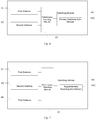
- Fig. 3 is a schematic diagram of a wireless communication device according to an exemplary embodiment.
- Fig. 4 is a block diagram of an electronic device according to an exemplary embodiment.
- Fig. 5 is a block diagram of an electronic device according to an exemplary embodiment.
- Fig. 6 is a block diagram of an electronic device according to an exemplary embodiment.
- Fig. 7 is a block diagram of an electronic device according to an exemplary embodiment.
- Fig. 8 is a block diagram of an electronic device according to an exemplary embodiment.
- Fig. 9 is a block diagram of an electronic device according to an exemplary embodiment.
- Fig. 10 is a block diagram of a terminal device according to an exemplary embodiment.
DETAILED DESCRIPTION
-
Reference will now be made in detail to exemplary embodiments, examples of which are illustrated in the accompanying drawings. The following description refers to the accompanying drawings in which the same numbers in different drawings represent the same or similar elements unless otherwise represented. The implementations set forth in the following description of exemplary embodiments do not represent all implementations consistent with the disclosure. Instead, they are merely examples of apparatuses and methods consistent with aspects related to the disclosure as recited in the appended claims.
-
Depending on how and on which portion the user holds the mobile phone, the performance of the antenna of the mobile phone is prone to be unstable and affect the communication quality of the mobile phone.
-
Embodiments of the present disclosure provide a method for switching an antenna, which is applied to a wireless communication device. The wireless communication device includes a standby redundant antenna, and when performance of an antenna in the operation state drops to a certain extent, the redundant antenna is enabled to improve the communication quality for the mobile phone.
-
In the embodiment of the present disclosure, the terms "first", "second" and the like are used to distinguish the same or similar items with substantially the same functions, and those skilled in the art can understand that the terms "first" and "second" do not limit the quantity and performing sequence.
-
The states of the antennas involved in the embodiments of the present disclosure include an operation state and a standby state.
-
The operation state refers to a state in which an antenna can transmit or receive. The operation state includes a primary operation state and an auxiliary operation state. The primary operation state refers to a state in which an antenna is used as a primary antenna, and the antenna in the primary operation state is used for transmission and primary reception. The auxiliary operation state refers to a state in which an antenna is used as an auxiliary antenna, and the antenna in the auxiliary operation state is used for auxiliary reception.
-
The standby state refers to a state in which an antenna is neither transmitting nor receiving.
-
Fig. 1 is a flowchart of a method for switching an antenna according to an exemplary embodiment, which is applied to a wireless communication device, including but not limited to a mobile phone, a tablet computer, a walkie-talkie, etc. The wireless communication device includes a first antenna and a second antenna. In an embodiment of the present disclosure, communication quality can be improved by switching the operation state of the antenna. The state of an antenna can be switched back and forth between the operation state and the standby state. For convenience of explanation, the initial state of the first antenna is assumed as in the operation state, and the initial state of the second antenna is assumed as in the standby state.
-
The method for switching an antenna includes steps 101-102.
-
In step 101, a performance parameter of the first antenna is detected.
-
The performance parameter of the antenna in the operation state is detected. The performance parameter includes at least one of strength of a received signal and sensitivity, for indicating the performance of the antenna in the operation state. When the performance parameter is not lower than a preset threshold, it indicates that the performance of the antenna can meet the communication requirements. When the performance parameter is lower than the preset threshold, it indicates that the performance of the antenna has been degraded and the communication quality has been affected.
-
In step 102, when the performance parameter of the first antenna is lower than the preset threshold, the second antenna is switched to the operation state, and the first antenna is switched to the standby state.
-
When the performance parameter of the first antenna is lower than the preset threshold, the states of the first antenna and the second antenna are interchanged. The first antenna is switched from the operation state to the standby state, and the second antenna is switched from the standby state to the operation state.
-
The operation state includes a primary operation state and an auxiliary operation state. The preset threshold in this embodiment may include a first preset threshold and a second preset threshold.
-
The first preset threshold is used to determine the performance of the antenna in the primary operation state. When the performance parameter of the antenna in the primary operation state is lower than the first preset threshold, it indicates that the performance of the antenna in the primary operation state has been degraded, and the communication quality has been affected.
-
The second preset threshold is used to determine the performance of the antenna in the auxiliary operation state. When the performance parameter of the antenna in the auxiliary operation state is lower than the second preset threshold, it indicates that the performance of the antenna in the auxiliary operation state has been degraded, and the communication quality has been affected.
-
The specific values of the first preset threshold and the second preset threshold may be experimentally measured empirical values, and the values of the two preset thresholds share no fixed relationship in size.
-
The first antenna being switched from the auxiliary operation state to the standby state is taken as an example. In one embodiment, the wireless communication device includes three antennas, a first antenna, a second antenna, and a third antenna, respectively. The first antenna is in the auxiliary operation state, the second antenna is in the standby state, and the third antenna is in the primary operation state.
-
When the performance of the antenna in the primary operation state is normal and the performance of the antenna in the auxiliary operation state has been degraded, the state of the antenna in the auxiliary operation state can be interchanged with the state of the antenna in the standby state. For example, when the performance parameter of the third antenna is not lower than the first preset threshold, and the performance parameter of the first antenna is lower than the second preset threshold, the second antenna is switched from the standby state to the auxiliary operation state, and the first antenna is switched from the auxiliary operation state to the standby state.
-
The method for switching an antenna provided by the embodiment of the present disclosure is applied to a wireless communication device which includes a first antenna and a second antenna. While the first antenna is in the operation state, the second antenna is in the standby state, and when the performance of the first antenna has been degraded to a certain extent, the second antenna is switched to the operation state and the first antenna is switched to the standby state. Thereby it can improve the communication quality of the mobile phone by enabling the standby antenna when the performance of the antenna in the operation state has been degraded.
-
Based on the method for switching an antenna provided by the above embodiment corresponding to Fig. 1, Fig. 2 is a flowchart of a method for switching an antenna according to an exemplary embodiment. In the embodiment corresponding to Fig. 2, the method for switching an antenna is further explained with reference to an example in which the states of antenna in the primary operation state and of the antenna in the auxiliary operation state are respectively interchanged with the state of the antenna in the standby state.
-
Some of the steps are the same as or similar to those of the embodiment corresponding to Fig. 1, and only the different steps will be described in detail below.
-
Referring to Fig. 2, the method for switching an antenna provided in this embodiment includes steps 201-205.
-
In step 201, an operation posture of the wireless communication device is detected.
-
The wireless communication device can include a sensor configured to detect operation posture of the wireless communication device. The operation posture refers to relative heights of various portions of the wireless communication device in space. Taking a mobile phone as an example, the operation posture includes a vertical screen posture, a horizontal screen posture, and an inverted posture.
-
In step 202, a performance parameter of the antenna in the primary operation state is detected when it is determined that the operation posture of the wireless communication device has been changed.
-
In one embodiment, when it is detected that the operation posture of the wireless communication device has been changed, the detection of the performance parameter of the primary antenna is triggered.
-
Taking the case where the wireless communication device is a mobile phone as an example, referring to Fig. 3, the wireless communication device includes a first antenna 31, and an initial state of the first antenna 31 is the primary operation state.
-
When the user changes the operation posture of the mobile phone, the portion where the user holds the mobile phone also changes, which may cause the parameter of the signal of the primary antenna to be degraded. Therefore, when the mobile phone detects that the operation posture has been changed, the mobile phone detects the performance parameter of the first antenna 31.
-
In step 203, the state of the antenna in the primary operation state is interchanged with the state of the antenna in the standby state.
-
When the performance parameter of the antenna in the primary operation state is lower than the first preset threshold, it indicates that the performance of the primary antenna has been degraded, and the communication quality has been affected. At this time, the antenna in the standby state is switched to the primary operation state.
-
Referring to Fig. 3, when the performance parameter of the first antenna 31 is lower than the first preset threshold, the second antenna 32 is switched from the standby state to the primary operation state, and the first antenna 31 is switched from the primary operation state to the standby state.
-
The state of one antenna can be switched back and forth between the primary operation state and the standby state. For example, after the second antenna 32 is switched from the standby state to the primary operation state, and the first antenna 31 is switched from the primary operation state to the standby state, when the performance parameter of the second antenna 32 is lower than the first preset threshold, the second antenna 32 can be switched back from the primary operation state to the standby state, and the first antenna 31 can be switched back from the standby state to the primary operation state.
-
In step 204, a performance parameter of the antenna in the auxiliary operation state is detected when it is determined that the operation posture of the wireless communication device has been changed.
-
There is no sequence between the step 204 and the step 202. For example, when it is determined that the operation posture of the wireless communication device has been changed, the performance parameter of the antenna in the primary operation state and the performance parameter of the antenna in the auxiliary operation state can be simultaneously detected. For another example, after the states of the antenna in the primary operation state and of the antenna in the standby state are interchanged, the process may go to step 204.
-
In step 205, the state of the antenna in the auxiliary operation state is interchanged with the state of the antenna in the standby state.
-
In one embodiment, when the performance parameter of the antenna in the auxiliary operation state is lower than the second preset threshold, the antenna in the auxiliary operation state is switched to the standby state, and the antenna in the standby state is switched to the auxiliary operation state.
-
Referring to Fig. 3, the wireless communication device further includes a third antenna 33. The initial state of the third antenna 33 is the auxiliary operation state. After the state switching in step 203, the current state of the first antenna 31 is the standby state. When the performance parameter of the third antenna 33 is lower than the second preset threshold, the third antenna 33 is switched from the auxiliary operation state to the standby state, and the first antenna 31 is switched from the standby state to the auxiliary operation state.
-
The state of one antenna can be switched back and forth between the auxiliary operation state and the standby state. For example, after the third antenna 33 is switched from the auxiliary operation state to the standby state, and the first antenna 31 is switched from the standby state to the auxiliary operation state, when the performance parameter of the first antenna 31 is lower than the second preset threshold, the first antenna 31 may be can be switched back from the auxiliary operation state to the standby state, and the third antenna 33 can be switched back from the standby state to the auxiliary operation state.
-
Further, the state of one antenna can be switched back and forth between the primary operation state and the auxiliary operation state. For example, the initial state of the first antenna 31 is the primary operation state, and the initial state of the third antenna 33 is the auxiliary operation state. When the performance parameter of the third antenna 33 is greater than the performance parameter of the first antenna 31, the third antenna 33 can be switched from the auxiliary operation state to the primary operation state, and the first antenna 31 can be switched from the primary operation state to the auxiliary operation state.
-
The method for switching an antenna provided by the embodiment of the present disclosure is applied to a wireless communication device including a first antenna and a second antenna. While the first antenna is in the operation state, and the second antenna is in the standby state, and when the performance of the first antenna has been degraded to a certain extent, the second antenna is switched to the operation state and the first antenna is switched to the standby state. Thereby it can improve the communication quality of the mobile phone by enabling the standby antenna when the performance of the antenna in the operation state has been degraded.
-
The following is a device embodiment of the present disclosure, which may be configured to implement the method embodiments of the present disclosure.
-
Fig. 4 is a block diagram of an electronic device according to an exemplary embodiment. The device may implement some or all of its functions by software, hardware or a combination of both for performing the method for switching an antenna described in the embodiments corresponding to Figs. 1-3. As shown in Fig. 4, the electronic device includes:
- a first antenna 41 in an operation state and a second antenna 42 in a standby state,
- a performance detecting module 43 configured to detect a performance parameter of the first antenna 41, the performance parameter including at least one of strength of a received signal and sensitivity; and
- a switching module 44 configured to, when the performance parameter of the first antenna 41 is lower than a preset threshold, switch the second antenna 42 to the operation state, and switch the first antenna 41 to the standby state.
-
As shown in Fig. 5, in an embodiment, the wireless communication device further includes: a posture detecting module 45 configured to detect an operation posture of the wireless communication device.
-
The performance detecting module 43 includes a triggering sub-module 431 configured to detect the performance parameter of the first antenna 41 when it is determined that the operation posture of the wireless communication device has been changed.
-
As shown in Fig. 6, in an embodiment, the operation state of the first antenna 41 is a primary operation state.
-
The switching module 44 includes a primary switching sub-module 441 configured to, when the performance parameter of the first antenna 41 is lower than a first preset threshold, switch the second antenna 42 to the primary operation state.
-
As shown in Fig. 7, in an embodiment, the wireless communication device further includes a third antenna 46, wherein the operation state of the third antenna 46 is an auxiliary operation state.
-
The switching module 44 includes a supplementary switching sub-module 442 configured to, when the performance parameter of the third antenna 46 is lower than a second preset threshold, switch the third antenna 46 to the standby state, and switch the first antenna 41 to the auxiliary operation state.
-
As shown in Fig. 8, in an embodiment, the operation state of the first antenna 41 is an auxiliary operation state, the wireless communication device further includes a third antenna 46, and the operation state of the third antenna 46 is a primary operation state.
-
The switching module 44 includes an auxiliary switching sub-module 443 configured to, when the performance parameter of the third antenna 46 is not lower than a first preset threshold, and the performance parameter of the first antenna 41 is lower than a second preset threshold, switch the second antenna 42 to the auxiliary operation state.
-
The electronic device provided by the embodiments of the present disclosure includes a first antenna and a second antenna. While the first antenna is in the operation state, the second antenna is in the standby state, and when the performance of the first antenna has been degraded to a certain extent, the second antenna is switched to the operation state and the first antenna is switched to the standby state. Thereby it can improve the communication quality of the mobile phone by enabling the standby antenna when the performance of the antenna in the operation state has been degraded.
-
Fig. 9 is a block diagram of an electronic device according to an exemplary embodiment. The device may implement some or all of its functions by software, hardware or a combination of both for performing the method for switching an antenna described in the embodiments corresponding to Figs. 1-3. As shown in Fig. 9, the electronic device 90 includes:
- a processor 901; and
- a memory 902 for storing instructions executable by the processor 901.
-
The electronic device 90 further includes a first antenna 903 in an operation state and a second antenna 904 in a standby state.
-
The processor 901 is configured to:
- detect a performance parameter of the first antenna 903, the performance parameter including at least one of strength of a received signal and sensitivity; and
- when the performance parameter of the first antenna 903 is lower than a preset threshold, switch the second antenna 904 to the operation state, and switch the first antenna 903 to the standby state.
-
In an embodiment, the processor 901 may be further configured to:
- detect an operation posture of the wireless communication device; and
- detect the performance parameter of the first antenna 903 when it is determined that the operation posture of the wireless communication device has been changed.
-
In an embodiment, the processor 901 may be further configured to:
- the operation state of the first antenna 903 is a primary operation state; and
- when the performance parameter of the first antenna 903 is lower than a first preset threshold, switch the second antenna 904 to the primary operation state.
-
In an embodiment, the wireless communication device further includes a third antenna 905, and the operation state of the third antenna 905 is an auxiliary operation state, and the processor 901 may be further configured to:
when the performance parameter of the third antenna 905 is lower than a second preset threshold, switch the third antenna 905 to the standby state, and switch the first antenna 903 to the auxiliary operation state.
-
In an embodiment, the operation state of the first antenna 903 is an auxiliary operation state, and the wireless communication device further includes a third antenna 905, and the operation state of the third antenna 905 is a primary operation state; and
the processor 901 may be further configured to:
when the performance parameter of the third antenna 905 is not lower than a first preset threshold, and the performance parameter of the first antenna 903 is lower than a second preset threshold, switch the second antenna 904 to the auxiliary operation state.
-
The electronic device provided by the embodiments of the present disclosure includes a first antenna and a second antenna. While the first antenna is in the operation state, the second antenna is in the standby state, and when the performance of the first antenna has been degraded to a certain extent, the second antenna is switched to the operation state and the first antenna is switched to the standby state. Thereby it can improve the communication quality of the mobile phone by enabling the standby antenna when the performance of the antenna in the operation state has been degraded.
-
The electronic device provided by the embodiment of the present disclosure may be a terminal device as shown in Fig. 10, and Fig. 10 is a block diagram of a terminal device according to an exemplary embodiment. The terminal device 100 may be a smart phone, a tablet computer, etc. The terminal device 100 is configured to perform the method for switching an antenna described in the foregoing embodiments corresponding to Figs. 1 to 3.
-
The terminal device 100 may include one or more of the following components: a processing component 1001, a memory 1002, a power component 1003, a multimedia component 1004, an audio component 1005, an input/output (I/O) interface 1006, a sensor component 1007, and a communication component 1008.
-
The processing component 1001 typically controls overall operations of the terminal device 100, such as the operations associated with display, telephone calls, data communications, camera operations, and recording operations. The processing component 1001 may include one or more processors 10011 to execute instructions, to perform all or part of the steps of the above method. Moreover, the processing component 1001 may include one or more modules which facilitate the interaction between the processing component 1001 and other components. For instance, the processing component 1001 may include a multimedia module to facilitate the interaction between the multimedia component 1004 and the processing component 1001.
-
The memory 1002 is configured to store various types of data to support the operation of the terminal device 100. Examples of such data include instructions for any applications or methods operated on the terminal device 100, contact data, phonebook data, messages, pictures, video, etc. The memory 1002 may be implemented using any type of volatile or non-volatile memory devices, or a combination thereof, such as a static random access memory (SRAM), an electrically erasable programmable read-only memory (EEPROM), an erasable programmable read-only memory (EPROM), a programmable read-only memory (PROM), a read-only memory (ROM), a magnetic memory, a flash memory, a magnetic or optical disk.
-
The power component 1003 provides power to various components of the terminal device 100. The power component 1003 may include a power management system, one or more power sources, and any other components associated with the generation, management, and distribution of power in the terminal device 100.
-
The multimedia component 1004 includes a screen providing an output interface between the terminal device 100 and the user. In some embodiments, the screen may include a liquid crystal display (LCD) and a touch panel (TP). If the screen includes the touch panel, the screen may be implemented as a touch screen to receive input signals from the user. The touch panel includes one or more touch sensors to sense touches, swipes, and gestures on the touch panel. The touch sensors may not only sense a boundary of a touch or swipe action, but also sense a period of time and a pressure associated with the touch or swipe action. In some embodiments, the multimedia component 1004 includes a front camera and/or a rear camera. The front camera and the rear camera may receive an external multimedia datum while the terminal device 100 is in an operation mode, such as a photographing mode or a video mode. Each of the front camera and the rear camera may be a fixed optical lens system or have focus and optical zoom capability.
-
The audio component 1005 is configured to output and/or input audio signals. For example, the audio component 1005 includes a microphone ("MIC") configured to receive an external audio signal when the terminal device 100 is in an operation mode, such as a call mode, a recording mode, and a voice recognition mode. The received audio signal may be further stored in the memory 1002 or transmitted via the communication component 1008. In some embodiments, the audio component 1005 further includes a speaker to output audio signals.
-
The I/O interface 1006 provides an interface between the processing component 1001 and peripheral interface modules, such as a keyboard, a click wheel, buttons, and the like. The buttons may include, but are not limited to, a home button, a volume button, a starting button, and a locking button.
-
The sensor component 1007 includes one or more sensors to provide status assessments of various aspects of the terminal device 100. For instance, the sensor component 1007 may detect an open/closed status of the terminal device 100, relative positioning of components, e.g., the display and the keypad, of the terminal device 100, a change in position of the terminal device 100 or a component of the terminal device 100, a presence or absence of user contact with the terminal device 100, an orientation or an acceleration/deceleration of the terminal device 100, and a change in temperature of the terminal device 100. The sensor component 1007 may include a proximity sensor configured to detect the presence of nearby objects without any physical contact. The sensor component 1007 may also include a light sensor, such as a CMOS or CCD image sensor, for use in imaging applications. In some embodiments, the sensor component 1007 may also include an accelerometer sensor, a gyroscope sensor, a magnetic sensor, a pressure sensor, or a temperature sensor.
-
The communication component 1008 is configured to facilitate communication, wired or wirelessly, between the terminal device 100 and other devices. The communication component 1008 can be provided with a plurality of antennas including a first antenna, a second antenna, and a third antenna. The terminal device 100 can access a wireless network based on a communication standard, such as Wireless-Fidelity (WiFi), 3G, 4G or 5G, or a combination thereof. In one exemplary embodiment, the communication component 1008 receives a broadcast signal or broadcast associated information from an external broadcast management system via a broadcast channel. In one exemplary embodiment, the communication component 1008 further includes a near field communication (NFC) module to facilitate short-range communications. For example, the NFC module may be implemented based on a radio frequency identification (RFID) technology, an infrared data association (IrDA) technology, an ultra-wideband (UWB) technology, a Bluetooth (BT) technology, and other technologies.
-
In exemplary embodiments, the terminal device 100 may be implemented with one or more application specific integrated circuits (ASICs), digital signal processors (DSPs), digital signal processing devices (DSPDs), programmable logic devices (PLDs), field programmable gate arrays (FPGAs), controllers, micro-controllers, microprocessors, or other electronic components, to perform the method for switching an antenna corresponding to the embodiments as shown in Figs. 1-3.
-
In exemplary embodiments, there is also provided a non-transitory computer-readable storage medium including instructions, such as included in the memory 1002, executable by the processor 10011 in the terminal device 100 to perform the above method. For example, the non-transitory computer-readable storage medium may be a ROM, a RAM, a CD-ROM, a magnetic tape, a floppy disc, an optical data storage device, and the like. When instructions in the storage medium are executed by the processor 10011 of the terminal device 100, causes the terminal device 100 to perform the method for switching an antenna corresponding to the embodiments as shown in Figs. 1-3. The method includes:
- detecting a performance parameter of the first antenna, the performance parameter including at least one of strength of a received signal and sensitivity; and
- when the performance parameter of the first antenna is lower than a preset threshold, switching the second antenna to the operation state, and switching the first antenna to the standby state.
-
In an embodiment, the method for switching an antenna further includes: detecting an operation posture of the wireless communication device; and
detecting a performance parameter of the first antenna including: detecting the performance parameter of the first antenna when it is determined that the operation posture of the wireless communication device has been changed.
-
In an embodiment, the operation state of the first antenna is a primary operation state; and
when the performance parameter of the first antenna is lower than a preset threshold, switching the second antenna to the operation state including:
when the performance parameter of the first antenna is lower than a first preset threshold, switching the second antenna to the primary operation state.
-
In an embodiment, the wireless communication device further includes a third antenna, and the operation state of the third antenna is an auxiliary operation state, and the method for switching an antenna further includes:
when the performance parameter of the third antenna is lower than a second preset threshold, switching the third antenna to the standby state, and switching the first antenna to the auxiliary operation state.
-
In an embodiment, the operation state of the first antenna is an auxiliary operation state, and the wireless communication device further includes a third antenna, and the operation state of the third antenna is a primary operation state; and
when the performance parameter of the first antenna is lower than a preset threshold, switching the second antenna to the operation state including:
when the performance parameter of the third antenna is not lower than a first preset threshold, and the performance parameter of the first antenna is lower than a second preset threshold, switching the second antenna to the auxiliary operation state.
-
In the terminal device and the storage medium provided by the embodiments of the present disclosure, while the first antenna is in the operation state, the second antenna is in the standby state, and when the performance of the first antenna has been degraded to a certain extent, the second antenna is switched to the operation state and the first antenna is switched to the standby state. Thereby it can improve the communication quality of the mobile phone by enabling the standby antenna when the performance of the antenna in the operation state has been degraded.
-
Other embodiments of the disclosure will be apparent to those skilled in the art from consideration of the specification and practice of the disclosure disclosed here.
-
It will be appreciated that the present disclosure is not limited to the exact construction that has been described above and illustrated in the accompanying drawings, and that various modifications and changes may be made without departing from the scope thereof. It is intended that the scope of the disclosure only be limited by the appended claims.