EP3618247A1 - Method for improving efficiency of power converter - Google Patents
Method for improving efficiency of power converter Download PDFInfo
- Publication number
- EP3618247A1 EP3618247A1 EP19173761.8A EP19173761A EP3618247A1 EP 3618247 A1 EP3618247 A1 EP 3618247A1 EP 19173761 A EP19173761 A EP 19173761A EP 3618247 A1 EP3618247 A1 EP 3618247A1
- Authority
- EP
- European Patent Office
- Prior art keywords
- switch
- mode
- load
- current
- current threshold
- Prior art date
- Legal status (The legal status is an assumption and is not a legal conclusion. Google has not performed a legal analysis and makes no representation as to the accuracy of the status listed.)
- Granted
Links
Images




Classifications
-
- H—ELECTRICITY
- H02—GENERATION; CONVERSION OR DISTRIBUTION OF ELECTRIC POWER
- H02M—APPARATUS FOR CONVERSION BETWEEN AC AND AC, BETWEEN AC AND DC, OR BETWEEN DC AND DC, AND FOR USE WITH MAINS OR SIMILAR POWER SUPPLY SYSTEMS; CONVERSION OF DC OR AC INPUT POWER INTO SURGE OUTPUT POWER; CONTROL OR REGULATION THEREOF
- H02M3/00—Conversion of DC power input into DC power output
- H02M3/02—Conversion of DC power input into DC power output without intermediate conversion into AC
- H02M3/04—Conversion of DC power input into DC power output without intermediate conversion into AC by static converters
- H02M3/10—Conversion of DC power input into DC power output without intermediate conversion into AC by static converters using discharge tubes with control electrode or semiconductor devices with control electrode
- H02M3/145—Conversion of DC power input into DC power output without intermediate conversion into AC by static converters using discharge tubes with control electrode or semiconductor devices with control electrode using devices of a triode or transistor type requiring continuous application of a control signal
- H02M3/155—Conversion of DC power input into DC power output without intermediate conversion into AC by static converters using discharge tubes with control electrode or semiconductor devices with control electrode using devices of a triode or transistor type requiring continuous application of a control signal using semiconductor devices only
- H02M3/156—Conversion of DC power input into DC power output without intermediate conversion into AC by static converters using discharge tubes with control electrode or semiconductor devices with control electrode using devices of a triode or transistor type requiring continuous application of a control signal using semiconductor devices only with automatic control of output voltage or current, e.g. switching regulators
-
- H—ELECTRICITY
- H02—GENERATION; CONVERSION OR DISTRIBUTION OF ELECTRIC POWER
- H02M—APPARATUS FOR CONVERSION BETWEEN AC AND AC, BETWEEN AC AND DC, OR BETWEEN DC AND DC, AND FOR USE WITH MAINS OR SIMILAR POWER SUPPLY SYSTEMS; CONVERSION OF DC OR AC INPUT POWER INTO SURGE OUTPUT POWER; CONTROL OR REGULATION THEREOF
- H02M3/00—Conversion of DC power input into DC power output
- H02M3/02—Conversion of DC power input into DC power output without intermediate conversion into AC
- H02M3/04—Conversion of DC power input into DC power output without intermediate conversion into AC by static converters
- H02M3/10—Conversion of DC power input into DC power output without intermediate conversion into AC by static converters using discharge tubes with control electrode or semiconductor devices with control electrode
- H02M3/145—Conversion of DC power input into DC power output without intermediate conversion into AC by static converters using discharge tubes with control electrode or semiconductor devices with control electrode using devices of a triode or transistor type requiring continuous application of a control signal
- H02M3/155—Conversion of DC power input into DC power output without intermediate conversion into AC by static converters using discharge tubes with control electrode or semiconductor devices with control electrode using devices of a triode or transistor type requiring continuous application of a control signal using semiconductor devices only
- H02M3/156—Conversion of DC power input into DC power output without intermediate conversion into AC by static converters using discharge tubes with control electrode or semiconductor devices with control electrode using devices of a triode or transistor type requiring continuous application of a control signal using semiconductor devices only with automatic control of output voltage or current, e.g. switching regulators
- H02M3/157—Conversion of DC power input into DC power output without intermediate conversion into AC by static converters using discharge tubes with control electrode or semiconductor devices with control electrode using devices of a triode or transistor type requiring continuous application of a control signal using semiconductor devices only with automatic control of output voltage or current, e.g. switching regulators with digital control
-
- H—ELECTRICITY
- H02—GENERATION; CONVERSION OR DISTRIBUTION OF ELECTRIC POWER
- H02M—APPARATUS FOR CONVERSION BETWEEN AC AND AC, BETWEEN AC AND DC, OR BETWEEN DC AND DC, AND FOR USE WITH MAINS OR SIMILAR POWER SUPPLY SYSTEMS; CONVERSION OF DC OR AC INPUT POWER INTO SURGE OUTPUT POWER; CONTROL OR REGULATION THEREOF
- H02M1/00—Details of apparatus for conversion
- H02M1/08—Circuits specially adapted for the generation of control voltages for semiconductor devices incorporated in static converters
-
- H—ELECTRICITY
- H02—GENERATION; CONVERSION OR DISTRIBUTION OF ELECTRIC POWER
- H02M—APPARATUS FOR CONVERSION BETWEEN AC AND AC, BETWEEN AC AND DC, OR BETWEEN DC AND DC, AND FOR USE WITH MAINS OR SIMILAR POWER SUPPLY SYSTEMS; CONVERSION OF DC OR AC INPUT POWER INTO SURGE OUTPUT POWER; CONTROL OR REGULATION THEREOF
- H02M3/00—Conversion of DC power input into DC power output
- H02M3/02—Conversion of DC power input into DC power output without intermediate conversion into AC
- H02M3/04—Conversion of DC power input into DC power output without intermediate conversion into AC by static converters
- H02M3/10—Conversion of DC power input into DC power output without intermediate conversion into AC by static converters using discharge tubes with control electrode or semiconductor devices with control electrode
- H02M3/145—Conversion of DC power input into DC power output without intermediate conversion into AC by static converters using discharge tubes with control electrode or semiconductor devices with control electrode using devices of a triode or transistor type requiring continuous application of a control signal
- H02M3/155—Conversion of DC power input into DC power output without intermediate conversion into AC by static converters using discharge tubes with control electrode or semiconductor devices with control electrode using devices of a triode or transistor type requiring continuous application of a control signal using semiconductor devices only
- H02M3/156—Conversion of DC power input into DC power output without intermediate conversion into AC by static converters using discharge tubes with control electrode or semiconductor devices with control electrode using devices of a triode or transistor type requiring continuous application of a control signal using semiconductor devices only with automatic control of output voltage or current, e.g. switching regulators
- H02M3/158—Conversion of DC power input into DC power output without intermediate conversion into AC by static converters using discharge tubes with control electrode or semiconductor devices with control electrode using devices of a triode or transistor type requiring continuous application of a control signal using semiconductor devices only with automatic control of output voltage or current, e.g. switching regulators including plural semiconductor devices as final control devices for a single load
-
- H—ELECTRICITY
- H02—GENERATION; CONVERSION OR DISTRIBUTION OF ELECTRIC POWER
- H02M—APPARATUS FOR CONVERSION BETWEEN AC AND AC, BETWEEN AC AND DC, OR BETWEEN DC AND DC, AND FOR USE WITH MAINS OR SIMILAR POWER SUPPLY SYSTEMS; CONVERSION OF DC OR AC INPUT POWER INTO SURGE OUTPUT POWER; CONTROL OR REGULATION THEREOF
- H02M1/00—Details of apparatus for conversion
- H02M1/0003—Details of control, feedback or regulation circuits
- H02M1/0009—Devices or circuits for detecting current in a converter
-
- H—ELECTRICITY
- H02—GENERATION; CONVERSION OR DISTRIBUTION OF ELECTRIC POWER
- H02M—APPARATUS FOR CONVERSION BETWEEN AC AND AC, BETWEEN AC AND DC, OR BETWEEN DC AND DC, AND FOR USE WITH MAINS OR SIMILAR POWER SUPPLY SYSTEMS; CONVERSION OF DC OR AC INPUT POWER INTO SURGE OUTPUT POWER; CONTROL OR REGULATION THEREOF
- H02M1/00—Details of apparatus for conversion
- H02M1/0003—Details of control, feedback or regulation circuits
- H02M1/0025—Arrangements for modifying reference values, feedback values or error values in the control loop of a converter
-
- H—ELECTRICITY
- H02—GENERATION; CONVERSION OR DISTRIBUTION OF ELECTRIC POWER
- H02M—APPARATUS FOR CONVERSION BETWEEN AC AND AC, BETWEEN AC AND DC, OR BETWEEN DC AND DC, AND FOR USE WITH MAINS OR SIMILAR POWER SUPPLY SYSTEMS; CONVERSION OF DC OR AC INPUT POWER INTO SURGE OUTPUT POWER; CONTROL OR REGULATION THEREOF
- H02M1/00—Details of apparatus for conversion
- H02M1/0003—Details of control, feedback or regulation circuits
- H02M1/0032—Control circuits allowing low power mode operation, e.g. in standby mode
-
- H—ELECTRICITY
- H02—GENERATION; CONVERSION OR DISTRIBUTION OF ELECTRIC POWER
- H02M—APPARATUS FOR CONVERSION BETWEEN AC AND AC, BETWEEN AC AND DC, OR BETWEEN DC AND DC, AND FOR USE WITH MAINS OR SIMILAR POWER SUPPLY SYSTEMS; CONVERSION OF DC OR AC INPUT POWER INTO SURGE OUTPUT POWER; CONTROL OR REGULATION THEREOF
- H02M1/00—Details of apparatus for conversion
- H02M1/0003—Details of control, feedback or regulation circuits
- H02M1/0038—Circuits or arrangements for suppressing, e.g. by masking incorrect turn-on or turn-off signals, e.g. due to current spikes in current mode control
-
- H—ELECTRICITY
- H02—GENERATION; CONVERSION OR DISTRIBUTION OF ELECTRIC POWER
- H02M—APPARATUS FOR CONVERSION BETWEEN AC AND AC, BETWEEN AC AND DC, OR BETWEEN DC AND DC, AND FOR USE WITH MAINS OR SIMILAR POWER SUPPLY SYSTEMS; CONVERSION OF DC OR AC INPUT POWER INTO SURGE OUTPUT POWER; CONTROL OR REGULATION THEREOF
- H02M1/00—Details of apparatus for conversion
- H02M1/0048—Circuits or arrangements for reducing losses
-
- H—ELECTRICITY
- H02—GENERATION; CONVERSION OR DISTRIBUTION OF ELECTRIC POWER
- H02M—APPARATUS FOR CONVERSION BETWEEN AC AND AC, BETWEEN AC AND DC, OR BETWEEN DC AND DC, AND FOR USE WITH MAINS OR SIMILAR POWER SUPPLY SYSTEMS; CONVERSION OF DC OR AC INPUT POWER INTO SURGE OUTPUT POWER; CONTROL OR REGULATION THEREOF
- H02M1/00—Details of apparatus for conversion
- H02M1/0048—Circuits or arrangements for reducing losses
- H02M1/0054—Transistor switching losses
-
- Y—GENERAL TAGGING OF NEW TECHNOLOGICAL DEVELOPMENTS; GENERAL TAGGING OF CROSS-SECTIONAL TECHNOLOGIES SPANNING OVER SEVERAL SECTIONS OF THE IPC; TECHNICAL SUBJECTS COVERED BY FORMER USPC CROSS-REFERENCE ART COLLECTIONS [XRACs] AND DIGESTS
- Y02—TECHNOLOGIES OR APPLICATIONS FOR MITIGATION OR ADAPTATION AGAINST CLIMATE CHANGE
- Y02B—CLIMATE CHANGE MITIGATION TECHNOLOGIES RELATED TO BUILDINGS, e.g. HOUSING, HOUSE APPLIANCES OR RELATED END-USER APPLICATIONS
- Y02B70/00—Technologies for an efficient end-user side electric power management and consumption
- Y02B70/10—Technologies improving the efficiency by using switched-mode power supplies [SMPS], i.e. efficient power electronics conversion e.g. power factor correction or reduction of losses in power supplies or efficient standby modes
Definitions
- the present invention relates to method for improving efficiency of power converter, and more particularly, to method improving efficiency by controlling an inductor current to ripple with constant peaks and varied valleys during an intermediate mode between a light-load mode and a heavy-load mode.
- Power converter such as DC-DC buck (e.g., step-down) converter
- DC-DC buck e.g., step-down
- DC-DC buck direct-current converter
- modern electronics such as smart phone, mobile phone, tablet/notebook/portable computer, digital camera, digital camcorder, handheld game console, or wearable gadget (glasses, wrest ring, watch, armlet, earphone, headset), etc.
- FIG. 1a illustrates a conventional power converter 100
- FIG. 1b illustrates operation of the power converter 100
- FIG. 1c illustrates power conversion efficiency of the power converter 100.
- the power converter 100 includes two transistors as two switches sp1 and sp2, to cooperate with an inductor L0 and a capacitor C0 for supplying power to a load 110 at a node p1.
- the switch sp1 is coupled between a power source Vin and a node p0
- the switch sp2 is coupled between the node p0 and a ground voltage G.
- the inductor L0 is coupled between the nodes p0 and p1, and the capacitor C0 is coupled between the node p1 and the ground voltage G.
- an inductor current iL0 of the inductor L0 increases; when the switch sp1 turns off to stop conducting the power source Vin to the node p0, the inductor current iL0 decreases.
- the inductor current iL0 ripples. Via the inductor L0 and the capacitor C0, the inductor current iL0 results in an output voltage Vout and a load current iLoad at the node p1 to supply power to the load 110.
- the conventional power converter 100 utilizes PFM and PWM modes for different load demands. As shown in FIG. 1b , before a time point tp1, the load 110 drains less power and the load current iLoad is low, the power converter 100 operates in the PFM mode for controlling the switch sp1 to cycle between on and off less frequently, and a switch frequency of the switch sp1, which may be a reciprocal of a period during which the switch sp1 is turned on and off once, is low.
- the load 110 demands more power and the load current iLoad rises, so the power converter 100 exits the PFM mode and enters the PWM mode for controlling the switch sp1 to cycle between on and off more frequently, and the switch frequency of the switch sp1 steps up to a higher frequency fmax.
- the efficiency achieved when the demanded load falls from the values a4, a3, a2 to a1 (along the curve ec2) is worse than the efficiency achieved when the demanded load rises from the values a1, a2, a3 to a4 (along the curve ec1).
- the curve ec1 drops along a sudden downward ramp at the load vale a3, rather than a slowly varying curve.
- an objective of the invention is providing a method (e.g., 300 in FIG. 3 ) for improving efficiency of a power converter (e.g., 200 in FIG. 2 ) which may include a switch (e.g., sw1) coupled between a power source (e.g., Vin) and a middle node (e.g., n0), along with a control logic (e.g., 220) coupled to the switch.
- the power converter may supply an inductor current (e.g., iL1) at the middle node to result in an output voltage (e.g., Vo) and a load current (e.g., iLoad).
- the method may include: during an intermediate mode (e.g., 320 in FIGs. 3 and 4 ), controlling the inductor current to ripple with peaks at a peak current threshold (e.g., I_peak in FIG. 4 ) and valleys which may vary as the load current varies.
- the method may further include: during a light-load mode (e.g., 310 in FIGs. 3 and 4 ), controlling the inductor current to ripple with peaks at the peak current threshold and valleys at a bottom current threshold (e.g., I_z in FIG. 4 ) by the control logic.
- the peak current threshold may be a constant value.
- the bottom current threshold may be a constant value less than the peak current threshold, e.g., the bottom current threshold may be a constant value close to zero or equal to zero.
- the method may further include: during a heavy-load mode (e.g., 330 in FIGs. 3 and 4 ), controlling the inductor current to ripple in a narrower range comparing to a range in which the inductor current ripples during the light-load mode.
- a heavy-load mode e.g., 330 in FIGs. 3 and 4
- the method may further include: after exiting the light-load mode, entering the intermediate mode before entering the heavy-load mode; and, after exiting the heavy-load mode, entering the intermediate mode before entering the light-load mode.
- controlling the inductor current to ripple in the narrower range during the heavy-load mode may include following operations: by the control logic, determining when to turn on the switch according to an amount of an error between a reference voltage (e.g., Vref in FIG. 2 ) and the output voltage; and, turning off the switch when a predetermined interval has elapsed after turning on the switch.
- a reference voltage e.g., Vref in FIG. 2
- the method may further include (e.g., 318 in FIG. 3 ): determining whether to enter the intermediate mode from the heavy-load mode according to whether the peak(s) of the inductor current is/are lower than a mode-switching current threshold.
- the mode-switching current threshold may equal the peak current threshold.
- the method may further include (e.g., 314 in FIG. 3 ): determining whether to enter the heavy-load mode from the intermediate mode according to whether an on-time for the switch to remain on is shorter than a predetermined on-time threshold, such that a switch frequency for the switch to cycle between on and off during the heavy-load mode may be higher than the switch frequency during the intermediate mode.
- controlling the inductor current to ripple with peaks at the peak current threshold and valleys at the bottom current threshold during the light-load mode may include following operations: turning on the switch when the output voltage is lower than the reference voltage; and, turning off the switch when the inductor current reaches the peak current threshold.
- controlling the inductor current to ripple with peaks at the peak current threshold and valleys which may vary as the load current varies during the intermediate mode may include following operations: turning off the switch when the inductor current reaches the peak current threshold; and, after turning off the switch, determining when to stop turning off the switch (e.g., determining when to turn on the switch again) according to the amount of the error between the reference voltage and the output voltage.
- the method may further include (e.g., 308 in FIG. 3 ): determining whether to enter the light-load mode from the intermediate mode according to whether the inductor current reaches the bottom current threshold.
- the method may further include (e.g., 304 in FIG. 3 ): determining whether to enter the intermediate mode from the light-load mode according to whether an off-time for the switch to remain off is shorter than an off-time threshold.
- An objective of the invention is providing a method (e.g., 300 in FIG. 3 ) for improving efficiency of a power converter (e.g., 200 in FIG. 2 ).
- the power converter may supply an inductor current (e.g., iL1) at a middle node (e.g., n0) to result in an output voltage (e.g., Vo) and a load current (e.g., iLoad), and the power converter may include a switch (e.g., sw1) coupled between a power source (e.g., Vi) and the middle node, along with a control logic (e.g., 220) coupled to the switch.
- the method may include: during an intermediate mode (e.g., 320 in FIGs.
- the method may further include (e.g., 314 in FIG. 3 ): determining whether to enter a heavy-load mode (e.g., 330 in FIGs. 3 and 4 ) from the intermediate mode according to whether an on-time for the switch to remain on is shorter than a predetermined on-time threshold.
- a heavy-load mode e.g., 330 in FIGs. 3 and 4
- the method may further include (e.g., 318): determining whether to enter the intermediate mode from the heavy-load mode according to whether a peak of the inductor current is lower than a mode-switching current threshold which may equal the peak current threshold in an embodiment.
- the method may further include: during the heavy-load mode, determining when to turn on the switch according to the amount of error between the reference voltage and the output voltage, and turning off the switch when a predetermined interval has elapsed after turning on the switch.
- the method may further include (e.g., 308 in FIG. 3 ): determining whether to enter a light-load mode (e.g., 310 in FIGs. 3 and 4 ) from the intermediate mode according to whether the inductor current reaches a bottom current threshold (e.g., I_z in FIG. 4 ).
- a light-load mode e.g., 310 in FIGs. 3 and 4
- a bottom current threshold e.g., I_z in FIG. 4
- the method may further include (e.g., 304 in FIG. 3 ): determining whether to enter the intermediate mode from the light-load mode according to whether an off-time for the switch to remain off is shorter than an off-time threshold.
- the method may further include: during the light-load mode, turning on the switch when the output voltage is lower than the reference voltage, and turning off the switch when the inductor current reaches the peak current threshold.
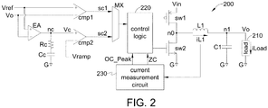
- FIG. 2 illustrates a power converter 200 according to an embodiment of the invention; for example, the power converter 200 may be a DC-DC buck converter.
- FIG. 3 illustrates a control flow 300 according to an embodiment of the invention; the control flow 300 may be applied to the power converter 200.
- FIG. 4 illustrates an operation example of the power converter 200.
- the power converter 200 may include two transistors as two switches sw1 and sw2, to cooperate with an inductor L1 and a capacitor C1 for supplying power to a load 210 at a node n1.
- the switch sw1 may be coupled between a power source Vin and a middle node n0, and the switch sw2 may be coupled between the node n0 and a ground voltage G.
- the inductor L1 may be coupled between the nodes n0 and n1, and the capacitor C1 may be coupled between the node n1 and the ground voltage G.
- the switch sw1 When the switch sw1 is turned on, the switch sw1 may conduct the power source Vin to the node n0; when the switch sw1 is turned off, the switch sw1 may stop conducting the power source Vin to the node n0.
- the switch sw2 When the switch sw2 is turned on, the switch sw2 may conduct the node n0 to the ground voltage G; when the switch sw2 is turned off, the switch sw2 may stop conducting the node n0 to the ground voltage G.
- the power converter 200 Via the switches sw1 and sw2, the power converter 200 may supply an inductor current iL1 at the node n0 to result in an output voltage Vo and a load current iLoad at the node n1.
- the power converter 200 may further include a control logic 220, a current measurement circuit 230, a multiplexer MX, two comparators cmp1 and cmp2, an error amplifier EA, a capacitor Cc and a resistor Rc.
- the comparator cmp1 may have two input terminals (marked by "+” and "-") respectively coupled to a reference voltage Vref and the output voltage Vo; the comparator cmp1 may compare the voltages Vref and Vo, and output a binary comparison result signal sc1 to the multiplexer MX to reflect if the reference voltage Vref is higher than the output voltage Vo.
- the capacitor Cc and the resistor Rc may be serially coupled between an internal node nc and the ground voltage G.
- the error amplifier EA may have two input terminals (marked by "+” and “-”) respectively coupled to the reference voltage Vref and the output voltage Vo.
- the error amplifier EA may amplify an error between the voltages Vref and Vo, and output an analog signal Vc at the node nc to reflect an amount of the error between the voltages Vref and Vo.
- the comparator cmp2 may have two input terminals (marked by “+” and “-”) respectively coupled to the signal Vc and a signal Vramp; the comparator cmp2 may compare the signals Vc and Vramp, and output a binary comparison result signal sc2 to the multiplexer MX to reflect if the signal Vc is higher than the signal Vramp.
- the reference voltage Vref may be a voltage of a constant value
- the signal Vramp may be a compensated ramp signal which may be formed by summing a periodic ramp signal (not shown) and a slope compensation signal (not shown).
- the current measurement circuit 230 may sense the inductor current iL1 and accordingly output two signals ZC and OC_Peak to the control logic 220.
- the current measurement circuit 230 may detect if the inductor current iL1 reaches (falls to) a bottom current threshold I_z and accordingly generate the signal ZC.
- the current measurement circuit 230 may also sense if the inductor current iL1 reaches (rises to) a peak current threshold I_peak and accordingly generate the signal OC_Peak.
- the bottom current threshold I_z may be a value less (lower) than the peak current threshold I_peak.
- the peak current threshold I_peak may be invariant to the load current iLoad and the output voltage Vo; i.e., value of the peak current threshold I_peak may remain the same when the load current iLoad or the output voltage Vo varies.
- the peak current threshold I_peak may a constant value.
- the bottom current threshold I_z may also be invariant to the load current iLoad and the output voltage Vo; for example, the bottom current threshold I_z may be a constant value less than the peak current threshold I_peak; in an embodiment, the bottom current threshold may be a (constant) value close to zero or equal to zero.
- the peak current threshold I_peak and/or the bottom current threshold I_z may be invariant to the load current iLoad and the output voltage Vo
- the peak current threshold I_peak and/or the bottom current threshold I_z may be customizable, programmable, configurable, reconfigurable and/or resettable; for example, the peak current threshold I_peak and/or the bottom current threshold I_z may be reconfigured to adapt different application scenarios, operation environments, and/or implementation considerations, etc.
- the control logic 220 coupled to the switches sw1 and sw2 may control on and off of the switches sw1 and sw2.
- the switch sw1 When the switch sw1 is turned on, the power source Vin may cause the inductor current iL1 to rise; when the switch sw1 is off, the inductor current iL1 may stop rising and/or fall.
- the control logic 220 may control the inductor current iL1 to ripple (swing) from valleys to peaks.
- the control logic 220 may control the power converter 200 to operate in (at least) three modes: a light-load mode 310, an intermediate mode 320 and a heavy-load mode 330, as shown in FIG. 3 .
- the control logic 220 may determine whether to exit one mode and enter another mode. As shown in FIG. 3 , after exiting the light-load mode 310, the control logic 220 may control the power converter 200 to enter the intermediate mode 320 before entering the heavy-load mode 330. On the other hand, after exiting the heavy-load mode 330, the control logic 220 may control the power converter 200 to enter the intermediate mode 320 before entering the light-load mode 310.
- the control logic 220 may control the inductor current iL1 to ripple with peaks (e.g., local maxima) and valleys (e.g., local minima) respectively at the peak current threshold I_peak and the bottom current threshold I_z, as shown in FIG. 4 . That is, during the light-load mode 310, the control logic 220 may control the inductor current iL1 to ripple between the peak current threshold I_peak and the bottom current threshold I_z.
- peaks e.g., local maxima
- valleys e.g., local minima
- control logic 220 may turn on the switch sw1 when the signal sc1 reflects that the output voltage Vo is lower than the reference voltage Vref, and may turn off the switch sw1 when the signal OC_Peak reflects that the inductor current iL1 reaches the peak current threshold I_peak.
- an off-time for the switch sw1 to remain off may vary as the load current iLoad varies; for example, the off-time may be shorter if the load current iLoad becomes higher.
- an on-time for the switch sw1 to remain on may be invariant to the load current iLoad, since the on-time is a duration for charging the inductor current iL1 from the bottom current threshold I_z to the peak current threshold I_peak.
- the control logic 220 may further execute steps 302 and 304 to determine whether to exit the light-load mode 310 and enter the intermediate mode 320.
- the control logic 220 may check the off-time of the switch sw1.
- the control logic 220 may check if a light-to-intermediate criterion is satisfied, wherein the light-to-intermediate criterion may be based on the off-time of the switch sw1.
- control logic 220 may control the power converter 200 to enter the intermediate mode 320 from the light-load mode 310, otherwise the control logic 220 may maintain in the light-load mode 310 and iterate back to step 302.
- control logic 220 may determine whether the light-to-intermediate criterion is satisfied (and therefore whether to exit the light-load mode 310) according to whether the off-time of the switch sw1 is shorter than an off-time threshold (not shown).
- control logic 220 may determine to enter the intermediate mode 320 when the off-time of the switch sw1 has been shorter than the off-time threshold for a predetermined number (one or more) of consecutive on-off cycles of the switch sw1, with each on-off cycle being a duration when the switch sw1 is turned on and off once. As depicted by the example in FIG.
- the power converter 200 may operate in the light-load mode 310 from time points t0 to t1; at the time point t1, the light-to-intermediate criterion is satisfied (e.g., the off-time of the switch sw1 is shorter than the off-time threshold), so the control logic 220 may control the power converter 200 to transit to the intermediate mode 320 from the light-load mode 310 at the time point t1.
- the control logic 220 may control the inductor current iL1 to ripple with peaks at the peak current threshold I_peak and valleys which may vary as the load current iLoad varies.
- the control logic 220 may turn off the switch sw1 when the signal OC_Peak reflects that the inductor current iL1 reaches the peak current threshold I_peak; and, after turning off the switch sw1, the control logic 220 may determine when to stop turning off the switch sw1 (e.g., determine when to turn on the switch sw1 again) according to the signal Vc which reflects the amount of error between the reference voltage Vref and the output voltage Vo.
- the control logic 220 may turn off the switch sw1 with shorter off-time, so the valleys of the inductor current iL1 may be higher as the load current iLoad increases.
- the peaks of the inductor current iL1 may stay at the peak current threshold I_peak, without varying with the load current iLoad.
- the control logic 220 may control a ripple range (difference between consecutive peak and valley) of the inductor current iL1 to vary as the load current iLoad varies; for example, the ripple range of the inductor current iL1 may become narrower as the load current iLoad increases.
- control logic 220 may cause the on-time, off-time, on-off cycle (sum of consecutive on-time and off-time) and on-off switch frequency (reciprocal of the on-off cycle) of the switch sw1 to vary as the load current iLoad varies; for example, as the load iLoad increases, the on-time, off-time and on-off cycle of the switch sw1 may be shorter, while the on-off switch frequency of the switch sw1 may be higher, as shown in FIG. 4 .
- control logic 220 may also execute steps 306 and 308 to determine whether to exit the intermediate mode 320 and enter the light-load mode 310, and may further execute steps 312 and 314 to determine whether to exit the intermediate mode 320 and enter the heavy-load mode 330.
- the current measurement circuit 230 may detect if the inductor current iL1 falls down to reach (and cross) the bottom current threshold I_z, and reflect the detection result to the control logic 220 by the signal ZC.
- the control logic 220 may check if an intermediate-to-light criterion is satisfied, wherein the intermediate-to-light criterion may be based on the signal ZC. When the intermediate-to-light criterion is met, the control logic 220 may control the power converter 200 to enter the light-load mode 310 from the intermediate mode 320, otherwise the control logic 220 may stay in the intermediate mode 320 and iterate back to step 306.
- control logic 220 may determine whether the intermediate-to-light criterion is satisfied (and therefore whether to exit the intermediate mode 320 and enter the light-load mode 310) according to whether the inductor current iL1 reaches the bottom current threshold I_z. For example, the control logic 220 may determine to enter the light-load mode 320 when the inductor current iL1 has reached the bottom current threshold I_z for a predetermined number (one or more) of consecutive on-off cycles of the switch sw1.
- the control logic 220 may check on-time of the switch sw1.
- the control logic 220 may check if an intermediate-to-heavy criterion is satisfied, wherein the intermediate-to-heavy criterion may be based on the on-time of the switch sw1.
- the control logic 220 may control the power converter 200 to enter the heavy-load mode 330 from the intermediate mode 320, otherwise the control logic 220 may stay in the intermediate mode 320 and iterate back to step 312.
- control logic 220 may determine whether the intermediate-to-heavy criterion is satisfied (and therefore whether to exit the intermediate mode 320 and enter the heavy-load mode 330) according to whether the on-time of the switch sw1 is shorter than an on-time threshold (not shown). For example, the control logic 220 may determine to enter the heavy-load mode 330 when the on-time of the switch sw1 is shorter than the on-time threshold. As depicted by the example in FIG.
- the power converter 200 may operate in the intermediate-mode 320 from time points t1 to t2; at the time point t2, the intermediate-to-heavy criterion is satisfied (e.g., the on-time of the switch sw1 is shorter than the on-time threshold), so the control logic 220 may control the power converter 200 to transit to the heavy-load mode 330 from the intermediate mode 320 at the time point t2.
- the switch frequency for the switch sw1 to cycle between on and off during the heavy-load mode 330 may be higher than the switch frequency during the intermediate mode 320.
- the control logic 220 may control the inductor current iL1 to ripple in a narrower range comparing to a range in which the inductor current iL1 ripples during the light-load mode 310.
- the ripple range of the inductor current iL1 in the heavy-load mode 330 may be narrower than the ripple range in the light-load mode 310.
- control logic 220 may determine when to turn on the switch sw1 according to the amount of error between the reference voltage Vref and the output voltage Vo (e.g., according to the signal Vc of the error amplifier), and may turn off the switch sw1 when a predetermined interval (e.g., a constant value, not shown) has elapsed after turning on the switch sw1.
- a predetermined interval e.g., a constant value, not shown
- the control logic 220 may turn off the switch sw1 with a shorter off-time, so peaks and valleys of the inductor current iL1 may be higher to track the increasing load current iLoad, as shown in FIG. 4 .
- the control logic 220 may control the inductor current iL1 to ripple with peaks at the peak current threshold I_peak during the light-load mode 310 and the intermediate mode 320, the control logic 220 may no longer constrain rippling of the inductor current iL1 to be bounded under the peak current threshold I_peak.
- the on-time, off-time and on-off cycle of the switch sw1 in the heavy-load mode 330 may be shorter than those in the light-load mode 310, and the on-off switch frequency of the switch sw1 in the heavy-load mode 330 may be higher than that in the light-load mode 310.
- the switch frequency of the switch sw1 may be as high as a frequency fmax, as shown in FIG. 4 .
- the control logic 220 may also execute steps 316 and 318 ( FIG. 3 ) to determine whether to exit the heavy-load mode 330 and enter the intermediate mode 320.
- the current measurement circuit 230 FIG. 2
- the control logic 220 may determine if a heavy-to-intermediate criterion is satisfied, wherein the intermediate criterion may be based on the peak value of the inductor current iL1.
- the control logic 220 may control the power converter 200 to enter the intermediate mode 320 from the heavy-load mode 310, otherwise the control logic 220 may stay in the heavy-load mode 330 and iterate back to step 316.
- the control logic 220 may determine whether the heavy-to-intermediate criterion is satisfied (and therefore whether to exit the heavy-load mode 330 and enter the intermediate mode 320) according to whether the peak(s) of the inductor current iL1 is/are lower than a mode-switching current threshold (not shown), which may be set equal to the peak current threshold I_peak.
- control logic 220 may determine to enter the intermediate mode 320 from the heavy-load mode 330 when peaks of the inductor current iL1 remain lower than the mode-switching current threshold for a predetermined number (one or more, e.g., 8) of consecutive on-off cycles of the switch sw1.
- the invention additionally interposes the intermediate mode 320 between the light-load mode 310 and the heavy-load mode 330
- the wide ripple range (of the inductor current iL1) in the light-load mode 310 may smoothly transit to the narrow ripple range in the heavy-load mod 330 by the gradually decreased ripple range during the intermediate mode 320.
- the low on-off switch frequency (of the switch sw1) in the light-load mode 310 may smoothly transit to the high on-off switch frequency in the heavy-load mod 330 by the gradually increased on-off switch frequency during the intermediate mode 320.
- the intermediate mode 320 will also smooth the transition from the heavy-load mode 330 to the light-load mode 310.
- the smooth transition between modes may help to improve power conversion efficiency of the power converter 200.
- FIG. 5 illustrating power conversion efficiency according to an embodiment of the invention.
- the demanded load load current
- FIG. 3 power conversion efficiency achieved by applying the control flow 300 ( FIG. 3 ) to the power converter 200 ( FIG. 2 )
- the control flow 300 FIG. 3
- FIG. 2 power conversion efficiency achieved by applying the control flow 300 ( FIG. 3 ) to the power converter 200 ( FIG. 2 )
- ec3 power conversion efficiency achieved by applying the control flow 300 ( FIG. 3 ) to the power converter 200 ( FIG. 2 )
- the cross-marked curves ec1 and circle-marked ec2 which are originally shown in FIG. 1c to depict power conversion efficiency of the conventional power converter 100 ( FIG. 1a ) are also shown in FIG. 5 .
- the power conversion according to the invention may achieve same efficiency when the load ascends and descends, as shown by the curve ec3, because the intermediate mode 320 is adopted between the light-load mode 310 and the heavy-load mode 330.
- the curve ec1 of prior art suffers from sudden downward ramp at load value a3
- the curve ec3 according to the invention may vary much more smoothly between load values a3 and a5, and remain higher than the curves ec1 and ec2 between the load values a3 and a5.
- the power converter 200 operating under the control flow 300 according to the invention may not only gain higher power conversion efficiency when the load increases from the load values a3 to a5 (as the curve ec3 is higher than the curve ec1 between the load values a3 and a5), but also gain higher power conversion efficiency when the load decreases from load values a5 to a1 (as the curve ec3 is higher than the curve ec2 between the load values a1 and a5).
- the power conversion according to the invention may effectively improve power conversion efficiency over a wide range of load values.
Landscapes
- Engineering & Computer Science (AREA)
- Power Engineering (AREA)
- Dc-Dc Converters (AREA)
Abstract
Description
- The present invention relates to method for improving efficiency of power converter, and more particularly, to method improving efficiency by controlling an inductor current to ripple with constant peaks and varied valleys during an intermediate mode between a light-load mode and a heavy-load mode.
- Power converter, such as DC-DC buck (e.g., step-down) converter, can convert unregulated power of a DC (direct-current) power source to regulated output voltage and load current for a load, and is therefore essential for modern electronics, such as smart phone, mobile phone, tablet/notebook/portable computer, digital camera, digital camcorder, handheld game console, or wearable gadget (glasses, wrest ring, watch, armlet, earphone, headset), etc.
- Please refer to
FIGs. 1a, 1b and1c ;FIG. 1a illustrates aconventional power converter 100,FIG. 1b illustrates operation of thepower converter 100, andFIG. 1c illustrates power conversion efficiency of thepower converter 100. As shown inFIG. 1a , thepower converter 100 includes two transistors as two switches sp1 and sp2, to cooperate with an inductor L0 and a capacitor C0 for supplying power to aload 110 at a node p1. The switch sp1 is coupled between a power source Vin and a node p0, the switch sp2 is coupled between the node p0 and a ground voltage G. The inductor L0 is coupled between the nodes p0 and p1, and the capacitor C0 is coupled between the node p1 and the ground voltage G. When the switch sp1 turns on to conduct the power source Vin to the node p0, an inductor current iL0 of the inductor L0 increases; when the switch sp1 turns off to stop conducting the power source Vin to the node p0, the inductor current iL0 decreases. As the switch sp1 cycles between on and off, the inductor current iL0 ripples. Via the inductor L0 and the capacitor C0, the inductor current iL0 results in an output voltage Vout and a load current iLoad at the node p1 to supply power to theload 110. - The
conventional power converter 100 utilizes PFM and PWM modes for different load demands. As shown inFIG. 1b , before a time point tp1, theload 110 drains less power and the load current iLoad is low, thepower converter 100 operates in the PFM mode for controlling the switch sp1 to cycle between on and off less frequently, and a switch frequency of the switch sp1, which may be a reciprocal of a period during which the switch sp1 is turned on and off once, is low. On the other hand, at the time point tp1, theload 110 demands more power and the load current iLoad rises, so thepower converter 100 exits the PFM mode and enters the PWM mode for controlling the switch sp1 to cycle between on and off more frequently, and the switch frequency of the switch sp1 steps up to a higher frequency fmax. - Disadvantages of the
conventional power converter 100 may be explained by referring toFIG. 1c . When the demanded load (load current) ascends from low to high, power conversion efficiency of thepower converter 100 is shown by a cross-marked curve ec1 inFIG. 1c ; on the other hand, when demanded load descends from high to low, the power conversion efficiency of thepower converter 100 is shown by a circle-marked curve ec2. It is first noted that the two curves ec1 and ec2 diverge and fail to meet each other; the curve ec2 is lower than the curve ec1 between load values a1 and a4. In other words, the efficiency achieved when the demanded load falls from the values a4, a3, a2 to a1 (along the curve ec2) is worse than the efficiency achieved when the demanded load rises from the values a1, a2, a3 to a4 (along the curve ec1). Furthermore, it is noted that the curve ec1 drops along a sudden downward ramp at the load vale a3, rather than a slowly varying curve. - To overcome disadvantages of the conventional power conversion, an objective of the invention is providing a method (e.g., 300 in
FIG. 3 ) for improving efficiency of a power converter (e.g., 200 inFIG. 2 ) which may include a switch (e.g., sw1) coupled between a power source (e.g., Vin) and a middle node (e.g., n0), along with a control logic (e.g., 220) coupled to the switch. The power converter may supply an inductor current (e.g., iL1) at the middle node to result in an output voltage (e.g., Vo) and a load current (e.g., iLoad). The method may include: during an intermediate mode (e.g., 320 inFIGs. 3 and4 ), controlling the inductor current to ripple with peaks at a peak current threshold (e.g., I_peak inFIG. 4 ) and valleys which may vary as the load current varies. In an embodiment, the method may further include: during a light-load mode (e.g., 310 inFIGs. 3 and4 ), controlling the inductor current to ripple with peaks at the peak current threshold and valleys at a bottom current threshold (e.g., I_z inFIG. 4 ) by the control logic. In an embodiment, the peak current threshold may be a constant value. In an embodiment, the bottom current threshold may be a constant value less than the peak current threshold, e.g., the bottom current threshold may be a constant value close to zero or equal to zero. - In an embodiment, the method may further include: during a heavy-load mode (e.g., 330 in
FIGs. 3 and4 ), controlling the inductor current to ripple in a narrower range comparing to a range in which the inductor current ripples during the light-load mode. - In an embodiment, the method may further include: after exiting the light-load mode, entering the intermediate mode before entering the heavy-load mode; and, after exiting the heavy-load mode, entering the intermediate mode before entering the light-load mode.
- In an embodiment, controlling the inductor current to ripple in the narrower range during the heavy-load mode may include following operations: by the control logic, determining when to turn on the switch according to an amount of an error between a reference voltage (e.g., Vref in
FIG. 2 ) and the output voltage; and, turning off the switch when a predetermined interval has elapsed after turning on the switch. - In an embodiment, the method may further include (e.g., 318 in
FIG. 3 ): determining whether to enter the intermediate mode from the heavy-load mode according to whether the peak(s) of the inductor current is/are lower than a mode-switching current threshold. In an embodiment, the mode-switching current threshold may equal the peak current threshold. - In an embodiment, the method may further include (e.g., 314 in
FIG. 3 ): determining whether to enter the heavy-load mode from the intermediate mode according to whether an on-time for the switch to remain on is shorter than a predetermined on-time threshold, such that a switch frequency for the switch to cycle between on and off during the heavy-load mode may be higher than the switch frequency during the intermediate mode. - In an embodiment, controlling the inductor current to ripple with peaks at the peak current threshold and valleys at the bottom current threshold during the light-load mode may include following operations: turning on the switch when the output voltage is lower than the reference voltage; and, turning off the switch when the inductor current reaches the peak current threshold.
- In an embodiment, controlling the inductor current to ripple with peaks at the peak current threshold and valleys which may vary as the load current varies during the intermediate mode may include following operations: turning off the switch when the inductor current reaches the peak current threshold; and, after turning off the switch, determining when to stop turning off the switch (e.g., determining when to turn on the switch again) according to the amount of the error between the reference voltage and the output voltage.
- In an embodiment, the method may further include (e.g., 308 in
FIG. 3 ): determining whether to enter the light-load mode from the intermediate mode according to whether the inductor current reaches the bottom current threshold. - In an embodiment, the method may further include (e.g., 304 in
FIG. 3 ): determining whether to enter the intermediate mode from the light-load mode according to whether an off-time for the switch to remain off is shorter than an off-time threshold. - An objective of the invention is providing a method (e.g., 300 in
FIG. 3 ) for improving efficiency of a power converter (e.g., 200 inFIG. 2 ). The power converter may supply an inductor current (e.g., iL1) at a middle node (e.g., n0) to result in an output voltage (e.g., Vo) and a load current (e.g., iLoad), and the power converter may include a switch (e.g., sw1) coupled between a power source (e.g., Vi) and the middle node, along with a control logic (e.g., 220) coupled to the switch. The method may include: during an intermediate mode (e.g., 320 inFIGs. 3 and4 ), turning on the switch to conduct the power source to the middle node, and turning off the switch to stop conducting the power source to the middle node when the inductor current reaches a peak current threshold (e.g., I_peak inFIG. 4 ); and, during the intermediate mode, after turning off the switch, determining when to stop turning off the switch (e.g., determining when to turn on the switch again) according to an amount of error between a reference voltage (e.g., Vref inFIG. 2 ) and the output voltage. - In an embodiment, the method may further include (e.g., 314 in
FIG. 3 ): determining whether to enter a heavy-load mode (e.g., 330 inFIGs. 3 and4 ) from the intermediate mode according to whether an on-time for the switch to remain on is shorter than a predetermined on-time threshold. - In an embodiment, the method may further include (e.g., 318): determining whether to enter the intermediate mode from the heavy-load mode according to whether a peak of the inductor current is lower than a mode-switching current threshold which may equal the peak current threshold in an embodiment.
- In an embodiment, the method may further include: during the heavy-load mode, determining when to turn on the switch according to the amount of error between the reference voltage and the output voltage, and turning off the switch when a predetermined interval has elapsed after turning on the switch.
- In an embodiment, the method may further include (e.g., 308 in
FIG. 3 ): determining whether to enter a light-load mode (e.g., 310 inFIGs. 3 and4 ) from the intermediate mode according to whether the inductor current reaches a bottom current threshold (e.g., I_z inFIG. 4 ). - In an embodiment, the method may further include (e.g., 304 in
FIG. 3 ): determining whether to enter the intermediate mode from the light-load mode according to whether an off-time for the switch to remain off is shorter than an off-time threshold. - In an embodiment, the method may further include: during the light-load mode, turning on the switch when the output voltage is lower than the reference voltage, and turning off the switch when the inductor current reaches the peak current threshold.
- Numerous objects, features and advantages of the present invention will be readily apparent upon a reading of the following detailed description of embodiments of the present invention when taken in conjunction with the accompanying drawings. However, the drawings employed herein are for the purpose of descriptions and should not be regarded as limiting.
- The above objects and advantages of the present invention will become more readily apparent to those ordinarily skilled in the art after reviewing the following detailed description and accompanying drawings, in which:
-
FIG. 1a (prior art) illustrates a conventional power converter; -
FIG. 1b (prior art) illustrates operation of the conventional power converter; -
FIG. 1c (prior art) illustrates power conversion efficiency of the conventional power converter; -
FIG. 2 illustrates a power converter according to an embodiment of the invention; -
FIG. 3 illustrates a power converter control flow according to an embodiment of the invention; -
FIG. 4 illustrates an operation example of the power converter shown inFIG. 2 ; and -
FIG. 5 illustrates power conversion efficiency achieved by applying the control flow shown inFIG. 3 to the power converter shown inFIG. 2 . - Please refer to
FIGs. 2 ,3 and4 .FIG. 2 illustrates apower converter 200 according to an embodiment of the invention; for example, thepower converter 200 may be a DC-DC buck converter.FIG. 3 illustrates acontrol flow 300 according to an embodiment of the invention; thecontrol flow 300 may be applied to thepower converter 200.FIG. 4 illustrates an operation example of thepower converter 200. - As shown in
FIG. 2 , thepower converter 200 may include two transistors as two switches sw1 and sw2, to cooperate with an inductor L1 and a capacitor C1 for supplying power to aload 210 at a node n1. The switch sw1 may be coupled between a power source Vin and a middle node n0, and the switch sw2 may be coupled between the node n0 and a ground voltage G. The inductor L1 may be coupled between the nodes n0 and n1, and the capacitor C1 may be coupled between the node n1 and the ground voltage G. - When the switch sw1 is turned on, the switch sw1 may conduct the power source Vin to the node n0; when the switch sw1 is turned off, the switch sw1 may stop conducting the power source Vin to the node n0. When the switch sw2 is turned on, the switch sw2 may conduct the node n0 to the ground voltage G; when the switch sw2 is turned off, the switch sw2 may stop conducting the node n0 to the ground voltage G. Via the switches sw1 and sw2, the
power converter 200 may supply an inductor current iL1 at the node n0 to result in an output voltage Vo and a load current iLoad at the node n1. - The
power converter 200 may further include acontrol logic 220, a current measurement circuit 230, a multiplexer MX, two comparators cmp1 and cmp2, an error amplifier EA, a capacitor Cc and a resistor Rc. The comparator cmp1 may have two input terminals (marked by "+" and "-") respectively coupled to a reference voltage Vref and the output voltage Vo; the comparator cmp1 may compare the voltages Vref and Vo, and output a binary comparison result signal sc1 to the multiplexer MX to reflect if the reference voltage Vref is higher than the output voltage Vo. The capacitor Cc and the resistor Rc may be serially coupled between an internal node nc and the ground voltage G. The error amplifier EA may have two input terminals (marked by "+" and "-") respectively coupled to the reference voltage Vref and the output voltage Vo. The error amplifier EA may amplify an error between the voltages Vref and Vo, and output an analog signal Vc at the node nc to reflect an amount of the error between the voltages Vref and Vo. The comparator cmp2 may have two input terminals (marked by "+" and "-") respectively coupled to the signal Vc and a signal Vramp; the comparator cmp2 may compare the signals Vc and Vramp, and output a binary comparison result signal sc2 to the multiplexer MX to reflect if the signal Vc is higher than the signal Vramp. In an embodiment, the reference voltage Vref may be a voltage of a constant value, and the signal Vramp may be a compensated ramp signal which may be formed by summing a periodic ramp signal (not shown) and a slope compensation signal (not shown). - In
FIG. 2 , the current measurement circuit 230 may sense the inductor current iL1 and accordingly output two signals ZC and OC_Peak to thecontrol logic 220. The current measurement circuit 230 may detect if the inductor current iL1 reaches (falls to) a bottom current threshold I_z and accordingly generate the signal ZC. The current measurement circuit 230 may also sense if the inductor current iL1 reaches (rises to) a peak current threshold I_peak and accordingly generate the signal OC_Peak. In an embodiment, the bottom current threshold I_z may be a value less (lower) than the peak current threshold I_peak. In an embodiment, the peak current threshold I_peak may be invariant to the load current iLoad and the output voltage Vo; i.e., value of the peak current threshold I_peak may remain the same when the load current iLoad or the output voltage Vo varies. For example, the peak current threshold I_peak may a constant value. Similarly, in an embodiment, the bottom current threshold I_z may also be invariant to the load current iLoad and the output voltage Vo; for example, the bottom current threshold I_z may be a constant value less than the peak current threshold I_peak; in an embodiment, the bottom current threshold may be a (constant) value close to zero or equal to zero. In an embodiment, while the peak current threshold I_peak and/or the bottom current threshold I_z may be invariant to the load current iLoad and the output voltage Vo, the peak current threshold I_peak and/or the bottom current threshold I_z may be customizable, programmable, configurable, reconfigurable and/or resettable; for example, the peak current threshold I_peak and/or the bottom current threshold I_z may be reconfigured to adapt different application scenarios, operation environments, and/or implementation considerations, etc. - According to the signals sc1, sc2, ZC and OC_Peak, the
control logic 220 coupled to the switches sw1 and sw2 may control on and off of the switches sw1 and sw2. When the switch sw1 is turned on, the power source Vin may cause the inductor current iL1 to rise; when the switch sw1 is off, the inductor current iL1 may stop rising and/or fall. As thecontrol logic 220 cycles the switch sw1 between on and off, thecontrol logic 220 may control the inductor current iL1 to ripple (swing) from valleys to peaks. - By turning on and off the switches sw1 and sw2 in different schemes, the
control logic 220 may control thepower converter 200 to operate in (at least) three modes: a light-load mode 310, anintermediate mode 320 and a heavy-load mode 330, as shown inFIG. 3 . In addition, thecontrol logic 220 may determine whether to exit one mode and enter another mode. As shown inFIG. 3 , after exiting the light-load mode 310, thecontrol logic 220 may control thepower converter 200 to enter theintermediate mode 320 before entering the heavy-load mode 330. On the other hand, after exiting the heavy-load mode 330, thecontrol logic 220 may control thepower converter 200 to enter theintermediate mode 320 before entering the light-load mode 310. - During the light-
load mode 310, thecontrol logic 220 may control the inductor current iL1 to ripple with peaks (e.g., local maxima) and valleys (e.g., local minima) respectively at the peak current threshold I_peak and the bottom current threshold I_z, as shown inFIG. 4 . That is, during the light-load mode 310, thecontrol logic 220 may control the inductor current iL1 to ripple between the peak current threshold I_peak and the bottom current threshold I_z. In an embodiment, to control the inductor current iL1 to ripple between the peak current threshold I_peak and the bottom current threshold I_z during the light-load mode 310, thecontrol logic 220 may turn on the switch sw1 when the signal sc1 reflects that the output voltage Vo is lower than the reference voltage Vref, and may turn off the switch sw1 when the signal OC_Peak reflects that the inductor current iL1 reaches the peak current threshold I_peak. - During the light-
load mode 310, while peaks and valleys of the inductor current iL1 may be respectively maintained at the peak current threshold I_peak and the bottom current threshold I_z without varying with the load current iLoad demanded by theload 210, an off-time for the switch sw1 to remain off may vary as the load current iLoad varies; for example, the off-time may be shorter if the load current iLoad becomes higher. On the other hand, during the light-load mode 310, an on-time for the switch sw1 to remain on may be invariant to the load current iLoad, since the on-time is a duration for charging the inductor current iL1 from the bottom current threshold I_z to the peak current threshold I_peak. - As shown in
FIG. 3 , during the light-load mode 310, thecontrol logic 220 may further executesteps load mode 310 and enter theintermediate mode 320. Instep 302, thecontrol logic 220 may check the off-time of the switch sw1. Instep 304, thecontrol logic 220 may check if a light-to-intermediate criterion is satisfied, wherein the light-to-intermediate criterion may be based on the off-time of the switch sw1. When the light-to-intermediate criterion is met, thecontrol logic 220 may control thepower converter 200 to enter theintermediate mode 320 from the light-load mode 310, otherwise thecontrol logic 220 may maintain in the light-load mode 310 and iterate back tostep 302. In an embodiment, thecontrol logic 220 may determine whether the light-to-intermediate criterion is satisfied (and therefore whether to exit the light-load mode 310) according to whether the off-time of the switch sw1 is shorter than an off-time threshold (not shown). For example, thecontrol logic 220 may determine to enter theintermediate mode 320 when the off-time of the switch sw1 has been shorter than the off-time threshold for a predetermined number (one or more) of consecutive on-off cycles of the switch sw1, with each on-off cycle being a duration when the switch sw1 is turned on and off once. As depicted by the example inFIG. 4 , thepower converter 200 may operate in the light-load mode 310 from time points t0 to t1; at the time point t1, the light-to-intermediate criterion is satisfied (e.g., the off-time of the switch sw1 is shorter than the off-time threshold), so thecontrol logic 220 may control thepower converter 200 to transit to theintermediate mode 320 from the light-load mode 310 at the time point t1. - During the
intermediate mode 320, thecontrol logic 220 may control the inductor current iL1 to ripple with peaks at the peak current threshold I_peak and valleys which may vary as the load current iLoad varies. In an embodiment, to control the inductor current iL1 to ripple with constant peaks (at the peak current threshold I_peak) and variable valleys during theintermediate mode 320, thecontrol logic 220 may turn off the switch sw1 when the signal OC_Peak reflects that the inductor current iL1 reaches the peak current threshold I_peak; and, after turning off the switch sw1, thecontrol logic 220 may determine when to stop turning off the switch sw1 (e.g., determine when to turn on the switch sw1 again) according to the signal Vc which reflects the amount of error between the reference voltage Vref and the output voltage Vo. For example, as the signal Vc increases, thecontrol logic 220 may turn off the switch sw1 with shorter off-time, so the valleys of the inductor current iL1 may be higher as the load current iLoad increases. On the other hand, the peaks of the inductor current iL1 may stay at the peak current threshold I_peak, without varying with the load current iLoad. In other words, during theintermediate mode 320, thecontrol logic 220 may control a ripple range (difference between consecutive peak and valley) of the inductor current iL1 to vary as the load current iLoad varies; for example, the ripple range of the inductor current iL1 may become narrower as the load current iLoad increases. Equivalently, during theintermediate mode 320, thecontrol logic 220 may cause the on-time, off-time, on-off cycle (sum of consecutive on-time and off-time) and on-off switch frequency (reciprocal of the on-off cycle) of the switch sw1 to vary as the load current iLoad varies; for example, as the load iLoad increases, the on-time, off-time and on-off cycle of the switch sw1 may be shorter, while the on-off switch frequency of the switch sw1 may be higher, as shown inFIG. 4 . - As shown in
FIG. 3 , during theintermediate mode 320, thecontrol logic 220 may also executesteps intermediate mode 320 and enter the light-load mode 310, and may further executesteps intermediate mode 320 and enter the heavy-load mode 330. - In
step 306, the current measurement circuit 230 (FIG. 2 ) may detect if the inductor current iL1 falls down to reach (and cross) the bottom current threshold I_z, and reflect the detection result to thecontrol logic 220 by the signal ZC. Instep 308, thecontrol logic 220 may check if an intermediate-to-light criterion is satisfied, wherein the intermediate-to-light criterion may be based on the signal ZC. When the intermediate-to-light criterion is met, thecontrol logic 220 may control thepower converter 200 to enter the light-load mode 310 from theintermediate mode 320, otherwise thecontrol logic 220 may stay in theintermediate mode 320 and iterate back tostep 306. In an embodiment, thecontrol logic 220 may determine whether the intermediate-to-light criterion is satisfied (and therefore whether to exit theintermediate mode 320 and enter the light-load mode 310) according to whether the inductor current iL1 reaches the bottom current threshold I_z. For example, thecontrol logic 220 may determine to enter the light-load mode 320 when the inductor current iL1 has reached the bottom current threshold I_z for a predetermined number (one or more) of consecutive on-off cycles of the switch sw1. - On the other hand, in
step 312, thecontrol logic 220 may check on-time of the switch sw1. Instep 314, thecontrol logic 220 may check if an intermediate-to-heavy criterion is satisfied, wherein the intermediate-to-heavy criterion may be based on the on-time of the switch sw1. When the intermediate-to-heavy criterion is met, thecontrol logic 220 may control thepower converter 200 to enter the heavy-load mode 330 from theintermediate mode 320, otherwise thecontrol logic 220 may stay in theintermediate mode 320 and iterate back tostep 312. In an embodiment, thecontrol logic 220 may determine whether the intermediate-to-heavy criterion is satisfied (and therefore whether to exit theintermediate mode 320 and enter the heavy-load mode 330) according to whether the on-time of the switch sw1 is shorter than an on-time threshold (not shown). For example, thecontrol logic 220 may determine to enter the heavy-load mode 330 when the on-time of the switch sw1 is shorter than the on-time threshold. As depicted by the example inFIG. 4 , thepower converter 200 may operate in the intermediate-mode 320 from time points t1 to t2; at the time point t2, the intermediate-to-heavy criterion is satisfied (e.g., the on-time of the switch sw1 is shorter than the on-time threshold), so thecontrol logic 220 may control thepower converter 200 to transit to the heavy-load mode 330 from theintermediate mode 320 at the time point t2. As the on-time of the switch sw1 during the heavy-load mode 330 may be shorter than the on-time during theintermediate mode 320, the switch frequency for the switch sw1 to cycle between on and off during the heavy-load mode 330 may be higher than the switch frequency during theintermediate mode 320. - During the heavy-
load mode 330, thecontrol logic 220 may control the inductor current iL1 to ripple in a narrower range comparing to a range in which the inductor current iL1 ripples during the light-load mode 310. In other word, under control of thecontrol logic 220, the ripple range of the inductor current iL1 in the heavy-load mode 330 may be narrower than the ripple range in the light-load mode 310. To control the inductor current iL1 to ripple in the narrower range during the heavy-load mode 330, thecontrol logic 220 may determine when to turn on the switch sw1 according to the amount of error between the reference voltage Vref and the output voltage Vo (e.g., according to the signal Vc of the error amplifier), and may turn off the switch sw1 when a predetermined interval (e.g., a constant value, not shown) has elapsed after turning on the switch sw1. For example, when the error between the voltages Vref and Vo increases as the load current iLoad increases, thecontrol logic 220 may turn off the switch sw1 with a shorter off-time, so peaks and valleys of the inductor current iL1 may be higher to track the increasing load current iLoad, as shown inFIG. 4 . In other words, while thecontrol logic 220 may control the inductor current iL1 to ripple with peaks at the peak current threshold I_peak during the light-load mode 310 and theintermediate mode 320, thecontrol logic 220 may no longer constrain rippling of the inductor current iL1 to be bounded under the peak current threshold I_peak. In associated with the narrower and wider ripple range of the inductor current iL1 respectively during the heavy-load mode 330 and the light-load mode 310, the on-time, off-time and on-off cycle of the switch sw1 in the heavy-load mode 330 may be shorter than those in the light-load mode 310, and the on-off switch frequency of the switch sw1 in the heavy-load mode 330 may be higher than that in the light-load mode 310. For example, during the heavy-load mode 330, the switch frequency of the switch sw1 may be as high as a frequency fmax, as shown inFIG. 4 . - During the heavy-
load mode 330, thecontrol logic 220 may also executesteps 316 and 318 (FIG. 3 ) to determine whether to exit the heavy-load mode 330 and enter theintermediate mode 320. Instep 316, the current measurement circuit 230 (FIG. 2 ) may sense peak value of the inductor current iL1. Instep 318, thecontrol logic 220 may determine if a heavy-to-intermediate criterion is satisfied, wherein the intermediate criterion may be based on the peak value of the inductor current iL1. When the heavy-to-intermediate criterion is met, thecontrol logic 220 may control thepower converter 200 to enter theintermediate mode 320 from the heavy-load mode 310, otherwise thecontrol logic 220 may stay in the heavy-load mode 330 and iterate back tostep 316. In an embodiment, thecontrol logic 220 may determine whether the heavy-to-intermediate criterion is satisfied (and therefore whether to exit the heavy-load mode 330 and enter the intermediate mode 320) according to whether the peak(s) of the inductor current iL1 is/are lower than a mode-switching current threshold (not shown), which may be set equal to the peak current threshold I_peak. For example, thecontrol logic 220 may determine to enter theintermediate mode 320 from the heavy-load mode 330 when peaks of the inductor current iL1 remain lower than the mode-switching current threshold for a predetermined number (one or more, e.g., 8) of consecutive on-off cycles of the switch sw1. - As depicted by the example in
FIG. 4 , because the invention additionally interposes theintermediate mode 320 between the light-load mode 310 and the heavy-load mode 330, the wide ripple range (of the inductor current iL1) in the light-load mode 310 may smoothly transit to the narrow ripple range in the heavy-load mod 330 by the gradually decreased ripple range during theintermediate mode 320. Similarly, the low on-off switch frequency (of the switch sw1) in the light-load mode 310 may smoothly transit to the high on-off switch frequency in the heavy-load mod 330 by the gradually increased on-off switch frequency during theintermediate mode 320. Though not shown inFIG. 4 , theintermediate mode 320 will also smooth the transition from the heavy-load mode 330 to the light-load mode 310. The smooth transition between modes may help to improve power conversion efficiency of thepower converter 200. Please refer toFIG. 5 illustrating power conversion efficiency according to an embodiment of the invention. When the demanded load (load current) ascends from low to high and descends from high to low, power conversion efficiency achieved by applying the control flow 300 (FIG. 3 ) to the power converter 200 (FIG. 2 ) may be shown by a diamond-marked curve ec3. For comparison between the invention and prior art, the cross-marked curves ec1 and circle-marked ec2, which are originally shown inFIG. 1c to depict power conversion efficiency of the conventional power converter 100 (FIG. 1a ), are also shown inFIG. 5 . - As shown in
FIG. 5 , it is first noted that, unlike theconventional power converter 100 which suffers from diverged efficiency curves ec1 and ec2 when the load respectively ascends and descends between load values a1 and a4, the power conversion according to the invention may achieve same efficiency when the load ascends and descends, as shown by the curve ec3, because theintermediate mode 320 is adopted between the light-load mode 310 and the heavy-load mode 330. It is also noted that, while the curve ec1 of prior art suffers from sudden downward ramp at load value a3, the curve ec3 according to the invention may vary much more smoothly between load values a3 and a5, and remain higher than the curves ec1 and ec2 between the load values a3 and a5. In other word, comparing to theconventional power converter 100, thepower converter 200 operating under thecontrol flow 300 according to the invention may not only gain higher power conversion efficiency when the load increases from the load values a3 to a5 (as the curve ec3 is higher than the curve ec1 between the load values a3 and a5), but also gain higher power conversion efficiency when the load decreases from load values a5 to a1 (as the curve ec3 is higher than the curve ec2 between the load values a1 and a5). - To sum up, by interposing the intermediate mode during which the inductor current may be controlled to ripple with constant peaks and variable valleys, the power conversion according to the invention may effectively improve power conversion efficiency over a wide range of load values.
- While the invention has been described in terms of what is presently considered to be the most practical and preferred embodiments, it is to be understood that the invention needs not be limited to the disclosed embodiment. On the contrary, it is intended to cover various modifications and similar arrangements included within the spirit and scope of the appended claims which are to be accorded with the broadest interpretation so as to encompass all such modifications and similar structures.
Claims (15)
- A method (300) for improving efficiency of a power converter (200) which comprises a switch (sw1) coupled between a power source (Vin) and a middle node (n0), and supplies an inductor current (iL1) at the middle node to result in an output voltage (Vo) and a load current (iLoad); the method comprising:
during an intermediate mode (320), controlling the inductor current to ripple with peaks at a peak current threshold (I_peak) and valleys which vary as the load current varies. - The method of claim 1 further comprising:after exiting a light-load mode (310), entering the intermediate mode before entering a heavy-load mode (330); andafter exiting the heavy-load mode, entering the intermediate mode before entering the light-load mode.
- The method of claim 2 further comprising:
determining whether to enter the intermediate mode from the light-load mode according to whether an off-time for the switch to remain off is shorter than an off-time threshold. - The method of any one of the claims 2 and 3 further comprising:
determining whether to enter the heavy-load mode from the intermediate mode according to whether an on-time for the switch to remain on is shorter than a predetermined on-time threshold, such that a switch frequency for the switch to cycle between on and off during the heavy-load mode is higher than the switch frequency during the intermediate mode. - The method of any one of the claims 2 to 4 further comprising:
determining whether to enter the intermediate mode from the heavy-load mode according to whether the peaks of the inductor current are lower than a mode-switching current threshold. - The method of claim 5, wherein the mode-switching current threshold equals the peak current threshold.
- The method of any one of the claims 2 to 6 further comprising:
determining whether to enter the light-load mode from the intermediate mode according to whether the inductor current reaches a bottom current threshold (I_z). - The method of claim 7 further comprising:
during the light-load mode, controlling the inductor current to ripple with peaks at the peak current threshold and valleys at the bottom current threshold. - The method of any one of the claims 7 and 8, wherein the bottom current threshold is a constant value.
- The method of any one of the claims 7 to 9, wherein the bottom current threshold is less than the peak current threshold.
- The method of any one of the claims 1 to 10, wherein controlling the inductor current to ripple with peaks at the peak current threshold and valleys which vary as the load current varies during the intermediate mode comprises:turning off the switch when the inductor current reaches the peak current threshold; andafter turning off the switch, determining when to stop turning off the switch according to an amount of an error between a reference voltage (Vref) and the output voltage.
- The method of claim 11 further comprising:
during the light-load mode, turning on the switch when the output voltage is lower than the reference voltage, and turning off the switch when the inductor current reaches the peak current threshold. - The method of any one of the claims 11 and 12 further comprising:
during the heavy-load mode, determining when to turn on the switch according to the amount of the error between the reference voltage and the output voltage, and turning off the switch when a predetermined interval has elapsed after turning on the switch. - The method of any one of the claims 2 to 12 further comprising:
during the heavy-load mode, controlling the inductor current to ripple in a narrower range comparing to a range in which the inductor current ripples during the light-load mode. - The method of any one of the claims 1 to 14, wherein the peak current threshold is a constant value.
Applications Claiming Priority (2)
| Application Number | Priority Date | Filing Date | Title |
|---|---|---|---|
| US201862723523P | 2018-08-28 | 2018-08-28 | |
| US16/395,354 US10707756B2 (en) | 2018-08-28 | 2019-04-26 | Method for improving efficiency of power converter |
Publications (2)
| Publication Number | Publication Date |
|---|---|
| EP3618247A1 true EP3618247A1 (en) | 2020-03-04 |
| EP3618247B1 EP3618247B1 (en) | 2021-07-21 |
Family
ID=66483898
Family Applications (1)
| Application Number | Title | Priority Date | Filing Date |
|---|---|---|---|
| EP19173761.8A Active EP3618247B1 (en) | 2018-08-28 | 2019-05-10 | Method for improving efficiency of power converter |
Country Status (4)
| Country | Link |
|---|---|
| US (1) | US10707756B2 (en) |
| EP (1) | EP3618247B1 (en) |
| CN (1) | CN110868067B (en) |
| TW (1) | TWI696337B (en) |
Families Citing this family (3)
| Publication number | Priority date | Publication date | Assignee | Title |
|---|---|---|---|---|
| TWI717233B (en) * | 2020-03-13 | 2021-01-21 | 群光電能科技股份有限公司 | Low power consumption protection circuit |
| TWI722905B (en) * | 2020-05-22 | 2021-03-21 | 茂達電子股份有限公司 | Inductor current detecting circuit |
| US11689103B2 (en) * | 2021-03-25 | 2023-06-27 | Infineon Technologies Austria Ag | Power supply monitoring and switching frequency control |
Citations (2)
| Publication number | Priority date | Publication date | Assignee | Title |
|---|---|---|---|---|
| US20100253308A1 (en) * | 2009-04-06 | 2010-10-07 | Yung-Hsin Chiang | Constant Current Driving System with Stable Output Current |
| US20150326123A1 (en) * | 2014-05-07 | 2015-11-12 | Rohm Co., Ltd. | Dc/dc converter, control circuit and control method thereof, and electronic apparatus |
Family Cites Families (17)
| Publication number | Priority date | Publication date | Assignee | Title |
|---|---|---|---|---|
| EP2144356B1 (en) * | 2008-07-09 | 2019-06-26 | Dialog Semiconductor GmbH | Buck converter threshold detection for automatic pulse skipping mode |
| CN103236791B (en) | 2008-08-21 | 2016-01-20 | 立锜科技股份有限公司 | PWM power converter with improved dynamic response and its control method |
| JP4643701B2 (en) * | 2008-10-24 | 2011-03-02 | レノボ・シンガポール・プライベート・リミテッド | Noise-eliminating power supply |
| US8253397B2 (en) * | 2009-06-18 | 2012-08-28 | Analog Devices, Inc. | Switching converters with efficiently-controlled mode transitions |
| US8803489B2 (en) * | 2010-07-16 | 2014-08-12 | Virginia Tech Intellectual Properties, Inc. | Adaptive on-time control for power factor correction stage light load efficiency |
| US8994351B2 (en) * | 2011-08-02 | 2015-03-31 | Power Integrations, Inc. | Smooth mode transition plateau for a power supply controller |
| TWI459692B (en) * | 2011-12-23 | 2014-11-01 | Nat Univ Chung Cheng | Switch power supply with energy efficiency orientation |
| US9276470B2 (en) * | 2012-08-31 | 2016-03-01 | Maxim Integrated Products, Inc. | Multiphase switching converters operating over wide load ranges |
| JP6209022B2 (en) * | 2013-08-27 | 2017-10-04 | リコー電子デバイス株式会社 | Switching regulator |
| TWI523395B (en) | 2013-11-05 | 2016-02-21 | 通嘉科技股份有限公司 | Control methods for clock frequency in a switched mode power supply and relevant power controllers |
| TWI555317B (en) | 2013-11-27 | 2016-10-21 | 力智電子股份有限公司 | Power converter and slope detection controller and method thereof |
| US9774252B2 (en) * | 2014-06-30 | 2017-09-26 | Skyworks Solutions, Inc. | Mode control device, voltage converter, and mode control method |
| JP2016116336A (en) * | 2014-12-15 | 2016-06-23 | 株式会社東芝 | Power supply circuit and control method thereof |
| US9431900B2 (en) * | 2015-02-03 | 2016-08-30 | Astec International Limited | Dynamic operating frequency control of a buck power converter having a variable voltage output |
| JP6539534B2 (en) | 2015-07-31 | 2019-07-03 | ローム株式会社 | Power supply circuit |
| CN105071641B (en) * | 2015-08-14 | 2017-10-31 | 东南大学 | A kind of control method for improving Switching Power Supply dynamic response |
| US10033279B2 (en) | 2016-04-19 | 2018-07-24 | Mediatek Singapore Pte. Ltd. | DC-DC voltage converter and associated control method capable of dynamically adjusting upper boundary of inductor current |
-
2019
- 2019-04-26 US US16/395,354 patent/US10707756B2/en active Active
- 2019-05-10 EP EP19173761.8A patent/EP3618247B1/en active Active
- 2019-08-20 TW TW108129712A patent/TWI696337B/en active
- 2019-08-27 CN CN201910794425.7A patent/CN110868067B/en active Active
Patent Citations (2)
| Publication number | Priority date | Publication date | Assignee | Title |
|---|---|---|---|---|
| US20100253308A1 (en) * | 2009-04-06 | 2010-10-07 | Yung-Hsin Chiang | Constant Current Driving System with Stable Output Current |
| US20150326123A1 (en) * | 2014-05-07 | 2015-11-12 | Rohm Co., Ltd. | Dc/dc converter, control circuit and control method thereof, and electronic apparatus |
Also Published As
| Publication number | Publication date |
|---|---|
| EP3618247B1 (en) | 2021-07-21 |
| CN110868067A (en) | 2020-03-06 |
| US10707756B2 (en) | 2020-07-07 |
| CN110868067B (en) | 2021-03-19 |
| TW202010229A (en) | 2020-03-01 |
| US20200076300A1 (en) | 2020-03-05 |
| TWI696337B (en) | 2020-06-11 |
Similar Documents
| Publication | Publication Date | Title |
|---|---|---|
| US11671012B2 (en) | Adaptive minimum on time control for a switching regulator | |
| US9287781B2 (en) | Single inductor multiple output converter | |
| US8248040B2 (en) | Time-limiting mode (TLM) for an interleaved power factor correction (PFC) converter | |
| US7733068B2 (en) | DC-DC converter | |
| US11290006B2 (en) | SIDO buck with negative current | |
| EP3618247B1 (en) | Method for improving efficiency of power converter | |
| US12470139B2 (en) | Control circuit with peak current limit for switching converters and control method thereof | |
| JP2017147787A (en) | Multi-output dc-dc converter | |
| US11095220B2 (en) | Voltage regulation replica transistors, comparator, ramp signal, and latch circuit | |
| US20160276928A1 (en) | Slew Rate Enhancement For Transient Load Step Response | |
| CN114616737A (en) | Voltage regulation circuit, equipment and method | |
| Moon et al. | Load-independent current control technique of a single-inductor multiple-output switching DC–DC converter | |
| US11703897B2 (en) | LDO overshoot protection in a cascaded architecture | |
| US7560916B2 (en) | Voltage-locked loop | |
| US12301096B2 (en) | Constant ripple algorithm in DCM for buck converter | |
| Chen et al. | Integrated non-inverting buck-boost DC-DC converter with average-current-mode control | |
| TWI671616B (en) | Regulator for dc-dc hybrid-mode power regulation | |
| CN113906661A (en) | Techniques for controlling Single Inductor Multiple Output (SIMO) Switched Mode Power Supplies (SMPS) | |
| JP4514811B2 (en) | Booster circuit and power supply device | |
| US20140092644A1 (en) | Switching power supply device and method for circuit design of the switching power supply device | |
| Bi et al. | Modeling and simulation of dual-mode DC/DC buck converter | |
| US10389249B2 (en) | Switching regulator having adjustable inductor current threshold and control method thereof | |
| JP3955058B2 (en) | DC-DC converter | |
| Ma et al. | A high efficiency adaptive current mode step-up/step-down DC–DC converter with four modes for smooth transition | |
| Wu et al. | A new adaptive mode-switching mechanism with current-mode CMOS DC-DC converter |
Legal Events
| Date | Code | Title | Description |
|---|---|---|---|
| PUAI | Public reference made under article 153(3) epc to a published international application that has entered the european phase |
Free format text: ORIGINAL CODE: 0009012 |
|
| STAA | Information on the status of an ep patent application or granted ep patent |
Free format text: STATUS: REQUEST FOR EXAMINATION WAS MADE |
|
| 17P | Request for examination filed |
Effective date: 20190510 |
|
| AK | Designated contracting states |
Kind code of ref document: A1 Designated state(s): AL AT BE BG CH CY CZ DE DK EE ES FI FR GB GR HR HU IE IS IT LI LT LU LV MC MK MT NL NO PL PT RO RS SE SI SK SM TR |
|
| AX | Request for extension of the european patent |
Extension state: BA ME |
|
| STAA | Information on the status of an ep patent application or granted ep patent |
Free format text: STATUS: EXAMINATION IS IN PROGRESS |
|
| 17Q | First examination report despatched |
Effective date: 20200707 |
|
| GRAP | Despatch of communication of intention to grant a patent |
Free format text: ORIGINAL CODE: EPIDOSNIGR1 |
|
| STAA | Information on the status of an ep patent application or granted ep patent |
Free format text: STATUS: GRANT OF PATENT IS INTENDED |
|
| INTG | Intention to grant announced |
Effective date: 20210223 |
|
| GRAS | Grant fee paid |
Free format text: ORIGINAL CODE: EPIDOSNIGR3 |
|
| GRAA | (expected) grant |
Free format text: ORIGINAL CODE: 0009210 |
|
| STAA | Information on the status of an ep patent application or granted ep patent |
Free format text: STATUS: THE PATENT HAS BEEN GRANTED |
|
| AK | Designated contracting states |
Kind code of ref document: B1 Designated state(s): AL AT BE BG CH CY CZ DE DK EE ES FI FR GB GR HR HU IE IS IT LI LT LU LV MC MK MT NL NO PL PT RO RS SE SI SK SM TR |
|
| RAP3 | Party data changed (applicant data changed or rights of an application transferred) |
Owner name: MEDIATEK INC. |
|
| REG | Reference to a national code |
Ref country code: GB Ref legal event code: FG4D |
|
| RIN1 | Information on inventor provided before grant (corrected) |
Inventor name: CHIU, CHAO-CHANG Inventor name: HSU, KUO-CHUN |
|
| REG | Reference to a national code |
Ref country code: CH Ref legal event code: EP |
|
| REG | Reference to a national code |
Ref country code: DE Ref legal event code: R096 Ref document number: 602019006198 Country of ref document: DE |
|
| REG | Reference to a national code |
Ref country code: AT Ref legal event code: REF Ref document number: 1413526 Country of ref document: AT Kind code of ref document: T Effective date: 20210815 |
|
| REG | Reference to a national code |
Ref country code: IE Ref legal event code: FG4D |
|
| REG | Reference to a national code |
Ref country code: LT Ref legal event code: MG9D |
|
| REG | Reference to a national code |
Ref country code: NL Ref legal event code: MP Effective date: 20210721 |
|
| REG | Reference to a national code |
Ref country code: AT Ref legal event code: MK05 Ref document number: 1413526 Country of ref document: AT Kind code of ref document: T Effective date: 20210721 |
|
| PG25 | Lapsed in a contracting state [announced via postgrant information from national office to epo] |
Ref country code: SE Free format text: LAPSE BECAUSE OF FAILURE TO SUBMIT A TRANSLATION OF THE DESCRIPTION OR TO PAY THE FEE WITHIN THE PRESCRIBED TIME-LIMIT Effective date: 20210721 Ref country code: RS Free format text: LAPSE BECAUSE OF FAILURE TO SUBMIT A TRANSLATION OF THE DESCRIPTION OR TO PAY THE FEE WITHIN THE PRESCRIBED TIME-LIMIT Effective date: 20210721 Ref country code: ES Free format text: LAPSE BECAUSE OF FAILURE TO SUBMIT A TRANSLATION OF THE DESCRIPTION OR TO PAY THE FEE WITHIN THE PRESCRIBED TIME-LIMIT Effective date: 20210721 Ref country code: FI Free format text: LAPSE BECAUSE OF FAILURE TO SUBMIT A TRANSLATION OF THE DESCRIPTION OR TO PAY THE FEE WITHIN THE PRESCRIBED TIME-LIMIT Effective date: 20210721 Ref country code: HR Free format text: LAPSE BECAUSE OF FAILURE TO SUBMIT A TRANSLATION OF THE DESCRIPTION OR TO PAY THE FEE WITHIN THE PRESCRIBED TIME-LIMIT Effective date: 20210721 Ref country code: PT Free format text: LAPSE BECAUSE OF FAILURE TO SUBMIT A TRANSLATION OF THE DESCRIPTION OR TO PAY THE FEE WITHIN THE PRESCRIBED TIME-LIMIT Effective date: 20211122 Ref country code: NL Free format text: LAPSE BECAUSE OF FAILURE TO SUBMIT A TRANSLATION OF THE DESCRIPTION OR TO PAY THE FEE WITHIN THE PRESCRIBED TIME-LIMIT Effective date: 20210721 Ref country code: NO Free format text: LAPSE BECAUSE OF FAILURE TO SUBMIT A TRANSLATION OF THE DESCRIPTION OR TO PAY THE FEE WITHIN THE PRESCRIBED TIME-LIMIT Effective date: 20211021 Ref country code: AT Free format text: LAPSE BECAUSE OF FAILURE TO SUBMIT A TRANSLATION OF THE DESCRIPTION OR TO PAY THE FEE WITHIN THE PRESCRIBED TIME-LIMIT Effective date: 20210721 Ref country code: BG Free format text: LAPSE BECAUSE OF FAILURE TO SUBMIT A TRANSLATION OF THE DESCRIPTION OR TO PAY THE FEE WITHIN THE PRESCRIBED TIME-LIMIT Effective date: 20211021 Ref country code: LT Free format text: LAPSE BECAUSE OF FAILURE TO SUBMIT A TRANSLATION OF THE DESCRIPTION OR TO PAY THE FEE WITHIN THE PRESCRIBED TIME-LIMIT Effective date: 20210721 |
|
| PG25 | Lapsed in a contracting state [announced via postgrant information from national office to epo] |
Ref country code: PL Free format text: LAPSE BECAUSE OF FAILURE TO SUBMIT A TRANSLATION OF THE DESCRIPTION OR TO PAY THE FEE WITHIN THE PRESCRIBED TIME-LIMIT Effective date: 20210721 Ref country code: LV Free format text: LAPSE BECAUSE OF FAILURE TO SUBMIT A TRANSLATION OF THE DESCRIPTION OR TO PAY THE FEE WITHIN THE PRESCRIBED TIME-LIMIT Effective date: 20210721 Ref country code: GR Free format text: LAPSE BECAUSE OF FAILURE TO SUBMIT A TRANSLATION OF THE DESCRIPTION OR TO PAY THE FEE WITHIN THE PRESCRIBED TIME-LIMIT Effective date: 20211022 |
|
| REG | Reference to a national code |
Ref country code: DE Ref legal event code: R097 Ref document number: 602019006198 Country of ref document: DE |
|
| PG25 | Lapsed in a contracting state [announced via postgrant information from national office to epo] |
Ref country code: DK Free format text: LAPSE BECAUSE OF FAILURE TO SUBMIT A TRANSLATION OF THE DESCRIPTION OR TO PAY THE FEE WITHIN THE PRESCRIBED TIME-LIMIT Effective date: 20210721 |
|
| PLBE | No opposition filed within time limit |
Free format text: ORIGINAL CODE: 0009261 |
|
| STAA | Information on the status of an ep patent application or granted ep patent |
Free format text: STATUS: NO OPPOSITION FILED WITHIN TIME LIMIT |
|
| PG25 | Lapsed in a contracting state [announced via postgrant information from national office to epo] |
Ref country code: SM Free format text: LAPSE BECAUSE OF FAILURE TO SUBMIT A TRANSLATION OF THE DESCRIPTION OR TO PAY THE FEE WITHIN THE PRESCRIBED TIME-LIMIT Effective date: 20210721 Ref country code: SK Free format text: LAPSE BECAUSE OF FAILURE TO SUBMIT A TRANSLATION OF THE DESCRIPTION OR TO PAY THE FEE WITHIN THE PRESCRIBED TIME-LIMIT Effective date: 20210721 Ref country code: RO Free format text: LAPSE BECAUSE OF FAILURE TO SUBMIT A TRANSLATION OF THE DESCRIPTION OR TO PAY THE FEE WITHIN THE PRESCRIBED TIME-LIMIT Effective date: 20210721 Ref country code: EE Free format text: LAPSE BECAUSE OF FAILURE TO SUBMIT A TRANSLATION OF THE DESCRIPTION OR TO PAY THE FEE WITHIN THE PRESCRIBED TIME-LIMIT Effective date: 20210721 Ref country code: CZ Free format text: LAPSE BECAUSE OF FAILURE TO SUBMIT A TRANSLATION OF THE DESCRIPTION OR TO PAY THE FEE WITHIN THE PRESCRIBED TIME-LIMIT Effective date: 20210721 Ref country code: AL Free format text: LAPSE BECAUSE OF FAILURE TO SUBMIT A TRANSLATION OF THE DESCRIPTION OR TO PAY THE FEE WITHIN THE PRESCRIBED TIME-LIMIT Effective date: 20210721 |
|
| 26N | No opposition filed |
Effective date: 20220422 |
|
| PG25 | Lapsed in a contracting state [announced via postgrant information from national office to epo] |
Ref country code: IT Free format text: LAPSE BECAUSE OF FAILURE TO SUBMIT A TRANSLATION OF THE DESCRIPTION OR TO PAY THE FEE WITHIN THE PRESCRIBED TIME-LIMIT Effective date: 20210721 |
|
| REG | Reference to a national code |
Ref country code: CH Ref legal event code: PL |
|
| REG | Reference to a national code |
Ref country code: BE Ref legal event code: MM Effective date: 20220531 |
|
| PG25 | Lapsed in a contracting state [announced via postgrant information from national office to epo] |
Ref country code: MC Free format text: LAPSE BECAUSE OF FAILURE TO SUBMIT A TRANSLATION OF THE DESCRIPTION OR TO PAY THE FEE WITHIN THE PRESCRIBED TIME-LIMIT Effective date: 20210721 Ref country code: LU Free format text: LAPSE BECAUSE OF NON-PAYMENT OF DUE FEES Effective date: 20220510 Ref country code: LI Free format text: LAPSE BECAUSE OF NON-PAYMENT OF DUE FEES Effective date: 20220531 Ref country code: CH Free format text: LAPSE BECAUSE OF NON-PAYMENT OF DUE FEES Effective date: 20220531 |
|
| PG25 | Lapsed in a contracting state [announced via postgrant information from national office to epo] |
Ref country code: IE Free format text: LAPSE BECAUSE OF NON-PAYMENT OF DUE FEES Effective date: 20220510 |
|
| PG25 | Lapsed in a contracting state [announced via postgrant information from national office to epo] |
Ref country code: BE Free format text: LAPSE BECAUSE OF NON-PAYMENT OF DUE FEES Effective date: 20220531 |
|
| P01 | Opt-out of the competence of the unified patent court (upc) registered |
Effective date: 20230607 |
|
| PG25 | Lapsed in a contracting state [announced via postgrant information from national office to epo] |
Ref country code: MK Free format text: LAPSE BECAUSE OF FAILURE TO SUBMIT A TRANSLATION OF THE DESCRIPTION OR TO PAY THE FEE WITHIN THE PRESCRIBED TIME-LIMIT Effective date: 20210721 Ref country code: CY Free format text: LAPSE BECAUSE OF FAILURE TO SUBMIT A TRANSLATION OF THE DESCRIPTION OR TO PAY THE FEE WITHIN THE PRESCRIBED TIME-LIMIT Effective date: 20210721 |
|
| PG25 | Lapsed in a contracting state [announced via postgrant information from national office to epo] |
Ref country code: HU Free format text: LAPSE BECAUSE OF FAILURE TO SUBMIT A TRANSLATION OF THE DESCRIPTION OR TO PAY THE FEE WITHIN THE PRESCRIBED TIME-LIMIT; INVALID AB INITIO Effective date: 20190510 |
|
| PG25 | Lapsed in a contracting state [announced via postgrant information from national office to epo] |
Ref country code: MT Free format text: LAPSE BECAUSE OF FAILURE TO SUBMIT A TRANSLATION OF THE DESCRIPTION OR TO PAY THE FEE WITHIN THE PRESCRIBED TIME-LIMIT Effective date: 20210721 |
|
| PGFP | Annual fee paid to national office [announced via postgrant information from national office to epo] |
Ref country code: DE Payment date: 20250325 Year of fee payment: 7 |
|
| PG25 | Lapsed in a contracting state [announced via postgrant information from national office to epo] |
Ref country code: TR Free format text: LAPSE BECAUSE OF FAILURE TO SUBMIT A TRANSLATION OF THE DESCRIPTION OR TO PAY THE FEE WITHIN THE PRESCRIBED TIME-LIMIT Effective date: 20210721 |
|
| PGFP | Annual fee paid to national office [announced via postgrant information from national office to epo] |
Ref country code: GB Payment date: 20260313 Year of fee payment: 8 |
|
| PGFP | Annual fee paid to national office [announced via postgrant information from national office to epo] |
Ref country code: FR Payment date: 20260309 Year of fee payment: 8 |