EP3618243A1 - Inverter-integrated rotating electric machine - Google Patents
Inverter-integrated rotating electric machine Download PDFInfo
- Publication number
- EP3618243A1 EP3618243A1 EP17907124.6A EP17907124A EP3618243A1 EP 3618243 A1 EP3618243 A1 EP 3618243A1 EP 17907124 A EP17907124 A EP 17907124A EP 3618243 A1 EP3618243 A1 EP 3618243A1
- Authority
- EP
- European Patent Office
- Prior art keywords
- electric machine
- rotating electric
- control circuit
- circuit board
- inverter
- Prior art date
- Legal status (The legal status is an assumption and is not a legal conclusion. Google has not performed a legal analysis and makes no representation as to the accuracy of the status listed.)
- Granted
Links
Images



Classifications
-
- H—ELECTRICITY
- H02—GENERATION; CONVERSION OR DISTRIBUTION OF ELECTRIC POWER
- H02K—DYNAMO-ELECTRIC MACHINES
- H02K11/00—Structural association of dynamo-electric machines with electric components or with devices for shielding, monitoring or protection
- H02K11/01—Structural association of dynamo-electric machines with electric components or with devices for shielding, monitoring or protection for shielding from electromagnetic fields, i.e. structural association with shields
- H02K11/014—Shields associated with stationary parts, e.g. stator cores
- H02K11/0141—Shields associated with casings, enclosures or brackets
-
- H—ELECTRICITY
- H02—GENERATION; CONVERSION OR DISTRIBUTION OF ELECTRIC POWER
- H02K—DYNAMO-ELECTRIC MACHINES
- H02K11/00—Structural association of dynamo-electric machines with electric components or with devices for shielding, monitoring or protection
- H02K11/30—Structural association with control circuits or drive circuits
-
- H—ELECTRICITY
- H02—GENERATION; CONVERSION OR DISTRIBUTION OF ELECTRIC POWER
- H02K—DYNAMO-ELECTRIC MACHINES
- H02K11/00—Structural association of dynamo-electric machines with electric components or with devices for shielding, monitoring or protection
- H02K11/30—Structural association with control circuits or drive circuits
- H02K11/33—Drive circuits, e.g. power electronics
-
- H—ELECTRICITY
- H02—GENERATION; CONVERSION OR DISTRIBUTION OF ELECTRIC POWER
- H02K—DYNAMO-ELECTRIC MACHINES
- H02K9/00—Arrangements for cooling or ventilating
-
- H—ELECTRICITY
- H02—GENERATION; CONVERSION OR DISTRIBUTION OF ELECTRIC POWER
- H02K—DYNAMO-ELECTRIC MACHINES
- H02K9/00—Arrangements for cooling or ventilating
- H02K9/22—Arrangements for cooling or ventilating by solid heat conducting material embedded in, or arranged in contact with, the stator or rotor, e.g. heat bridges
- H02K9/223—Heat bridges
-
- H—ELECTRICITY
- H02—GENERATION; CONVERSION OR DISTRIBUTION OF ELECTRIC POWER
- H02K—DYNAMO-ELECTRIC MACHINES
- H02K9/00—Arrangements for cooling or ventilating
- H02K9/22—Arrangements for cooling or ventilating by solid heat conducting material embedded in, or arranged in contact with, the stator or rotor, e.g. heat bridges
- H02K9/227—Heat sinks
-
- H—ELECTRICITY
- H02—GENERATION; CONVERSION OR DISTRIBUTION OF ELECTRIC POWER
- H02M—APPARATUS FOR CONVERSION BETWEEN AC AND AC, BETWEEN AC AND DC, OR BETWEEN DC AND DC, AND FOR USE WITH MAINS OR SIMILAR POWER SUPPLY SYSTEMS; CONVERSION OF DC OR AC INPUT POWER INTO SURGE OUTPUT POWER; CONTROL OR REGULATION THEREOF
- H02M7/00—Conversion of AC power input into DC power output; Conversion of DC power input into AC power output
- H02M7/42—Conversion of DC power input into AC power output without possibility of reversal
- H02M7/44—Conversion of DC power input into AC power output without possibility of reversal by static converters
- H02M7/48—Conversion of DC power input into AC power output without possibility of reversal by static converters using discharge tubes with control electrode or semiconductor devices with control electrode
-
- H—ELECTRICITY
- H02—GENERATION; CONVERSION OR DISTRIBUTION OF ELECTRIC POWER
- H02P—CONTROL OR REGULATION OF ELECTRIC MOTORS, ELECTRIC GENERATORS OR DYNAMO-ELECTRIC CONVERTERS; CONTROLLING TRANSFORMERS, REACTORS OR CHOKE COILS
- H02P11/00—Arrangements for controlling dynamo-electric converters
-
- H—ELECTRICITY
- H05—ELECTRIC TECHNIQUES NOT OTHERWISE PROVIDED FOR
- H05K—PRINTED CIRCUITS; CASINGS OR CONSTRUCTIONAL DETAILS OF ELECTRIC APPARATUS; MANUFACTURE OF ASSEMBLAGES OF ELECTRICAL COMPONENTS
- H05K1/00—Printed circuits
- H05K1/02—Details
- H05K1/0201—Thermal arrangements, e.g. for cooling, heating or preventing overheating
- H05K1/0203—Cooling of mounted components
- H05K1/021—Components thermally connected to metal substrates or heat-sinks by insert mounting
Definitions
- the present invention relates to an inverter-integrated rotating electric machine including, for example, a rotating electric machine configured to transmit and receive motive power to and from an internal combustion engine.
- the inverter-integrated rotating electric machine includes a motor and an inverter device, which is provided to the motor, and is configured to transmit and receive an electric power to and from the motor.
- the inverter device includes a power-system metal board, a control circuit board, and a metal shield plate.
- the power-system metal board is provided so as to be held in contact with a housing of the motor, and includes switching elements mounted thereto.
- the control circuit board is provided so as to be opposed to the power-systemmetalboard.
- the metal shield plate isprovided between the power-system metal board and the control circuit board.
- the present invention has been made to solve the problem described above, and has an object to provide an inverter-integrated rotating electric machine capable of suppressing an influence of electromagnetic noise between a peripheral device and a control circuit board.
- an inverter-integrated rotating electric machine including: a rotating electric machine main body; and an inverter device, which is provided to the rotating electric machine main body, and is configured to transmit and receive electric power to and from the rotating electric machine main body, wherein the inverter device includes: a heat sink configured to cool switching elements; a control circuit board, which is provided so as to be opposed to the heat sink, and includes a drive circuit configured to drive the switching elements; and a metal shield plate, which is provided so as to be opposed to the control circuit board in such a manner that the control circuit board is arranged between the metal shield plate and the heat sink, and is electrically connected to the heat sink.
- the control circuit board is provided between the heat sink and the metal shield plate. Therefore, the influence of the electromagnetic noise between the peripheral device for the inverter-integrated rotating electric machine and the control circuit board can be suppressed.
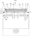
- FIG. 1 is a configuration view for illustrating an inverter-integrated rotating electric machine according to a first embodiment of the present invention.
- An inverter-integrated rotating electric machine 1A includes a rotating electric machine main body 2 and an inverter device 3A provided to the rotating electric machine main body 2.
- the rotating electric machine main body 2 includes a shaft 21, a bracket 22, and a pulley 23.
- the bracket 22 is configured to rotatably support the shaft 21.
- the pulley 23 is fixed to one end of the shaft 21 and is configured to rotate together with the shaft 21.
- a torque transmission belt (not shown) is mounted around thepulley23.
- An internal combustion engine (not shown) is connected to the torque transmission belt.
- the rotating electric machine main body 2 is configured to transmit and receive motive power to and from the internal combustion engine through intermediation of the torque transmission belt.
- the inverter device 3A includes a plurality of switching elements 31, a heat sink 32, a control circuit board 33, a metal shield plate 34A, and a resin portion 35.
- the heat sink 32 is configured to cool the switching elements 31.
- the control circuit board 33 is provided so as to be opposed to the heat sink 32.
- the metal shield plate 34A is provided so as to be opposed to the control circuit board 33 in such a manner that the control circuit board 33 is arranged between the metal shield plate 34A and the heat sink 32, and is electrically connected to the heat sink 32.
- the resin portion 35 is formed between the switching elements 31 and the control circuit board 33 and between the control circuit board 33 and the metal shield plate 34A.
- the switching elements 31 are formed of MOSFETs.
- the switching elements 31 are not limited to the MOSFETs, and may be other switching elements.
- the plurality of switching elements 31 are connected to each other so as to form a three-phase bridge circuit.
- the heat sink 32 is arranged so as to be opposed to the bracket 22 of the rotating electric machine main body 2.
- the heat sink 32 includes a heat sink main body 321, projecting portions 322, and projecting portions 323.
- the projecting portions 322 are formed at a peripheral edge of the heat sink main body 321 so as to project from the heat sink main body 321 toward the bracket 22.
- the projecting portions 323 project from the heat sink main body 321 toward the metal shield plate 34A.
- the projecting portions 323 are arranged on an inner side of the projecting portions 322 in an in-plane direction.
- a water passage or an air passage is formed in the heat sink main body 321.
- the switching elements 31 are held in surface contact with a surface of the heat sink main body 321, which is on the side opposite to a surface opposed to the bracket 22.
- the switching elements 31 are cooled with use of the water passage or the air passage of the heat sink main body 321.
- the heat sink 32 is of water-cooled type or air-cooled type.
- the control circuit board 33 includes a drive circuit and an electric power generation circuit.
- the drive circuit is configured to drive the switching elements 31.
- the electric power generation circuit is configured to operate a CPU and the drive circuit.
- Each of the drive circuit and the electric power generation circuit includes a plurality of electronic components 331.
- the control circuit board 33 is surrounded by the projecting portions 323 of the heat sink 32 in the in-plane direction.
- Examples of a resin for forming the resin portion 35 include, for example, an epoxy resin and a gel-like resin.
- the inverter-integrated rotating electric machine 1A further includes a plurality of screws 36 and a plurality of screws 37.
- the plurality of screws 36 are configured to fix the heat sink 32 to the bracket 22 of the rotating electric machine main body 2.
- the plurality of screws 37 are configured to fix the metal shield plate 34A to the heat sink 32.
- the screws 36 and the screws 37 are made of an electroconductive material.
- the inverter-integrated rotating electric machine 1A further includes a case 38 configured to surround the switching elements 31, the control circuit board 33, the metal shield plate 34A, and the resin portion 35 in the in-plane direction.
- the case 38 is made of a resin.
- the resin portion 35 is formed by causing a liquid resin to flow into the case 38. As a result of the formation of the resin portion 35 inside the case 38, reliability in terms of anti-vibration, water-proofness, and dust-proofness for the switching elements 31 and the control circuit board 33 is improved.
- FIG. 2 is a plan view for illustrating the metal shield plate 34A of FIG. 1 .
- the metal shield plate 34A has a plurality of through holes 341 and a plurality of through holes 342.
- the screws 37 are inserted into the through holes 341.
- the liquid resin is caused to flow into the through holes 342.
- the through holes 341 and the through holes 342 pass through the metal shield plate 34A in a plate thickness direction of the metal shield plate 34A.
- the metal shield plate 34A is formed of an electroconductive plate such as a copper plate, an aluminum plate, or an iron plate.
- a radial dimension of each of the through holes 341 is smaller than a radial dimension of each of the through holes 342.
- the radial direction of each of the through holes 342 is set to a preset dimension t1.
- a shape of each of the through holes 342 is circular.
- the shape of each of the through holes 342 may be other shapes. It is desired that the radial dimension t1 of each of the through holes 342 be equal to or smaller than one-twentieth of a wavelength ⁇ of electromagnetic noise, which is a target to be suppressed.
- the radial dimension t1 of each of the through holes 342 is adjusted in accordance with the wavelength ⁇ of the electromagnetic noise, which is the target to be suppressed. In other words, the radial dimension t1 of each of the through holes 342 is adjusted in accordance with a frequency of the electromagnetic noise, which is the target to be suppressed.
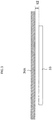
- FIG. 3 is an enlarged view for illustrating the control circuit board 33 and the metal shield plate 34A of FIG. 1 .
- the control circuit board 33 and the metal shield plate 34A are arranged in parallel to each other.
- a dimension between the control circuit board 33 and the metal shield plate 34A is set to a preset dimension t2. It is desired that the dimension t2 between the control circuit board 33 and the metal shield plate 34A be equal to or smaller than one-twentieth of the wavelength ⁇ of the electromagnetic noise, which is the target to be suppressed.
- the dimension t2 between the control circuit board 33 and the metal shield plate 34A is adjusted in accordance with the wavelength ⁇ of the electromagnetic noise, which is the target to be suppressed. In other words, the dimension t2 between the control circuit board 33 and the metal shield plate 34A is adjusted in accordance with the frequency of the electromagnetic noise, which is the target to be suppressed.
- propagation of the electromagnetic noise generated from the inverter device 3A to an outside of the inverter device 3A can be suppressed.
- propagation of electromagnetic noise generated from a peripheral device for the inverter-integrated rotating electric machine 1A to an inside of the inverter device 3A can be suppressed.
- an influence of the electromagnetic noise between the peripheral device for the inverter-integrated rotating electric machine 1A and the control circuit board 33 can be suppressed, thereby being capable of improving resistance of the inverter-integrated rotating electric machine against the electromagnetic noise.
- the inverter 3A includes the resin portion 35 formed between the switching elements 31 and the control circuit board 33 and between the control circuit board 33 and the metal shieldplate 34A.
- the reliability in terms of anti-vibration, water-proofness, and dust-proofness for the switching elements 31 and the control circuit board 33 can be improved.
- the through holes 342 into which the resin portion 35 in a liquid state is caused to flow are formed through the metal shield plate 34A.
- the dimension t1 of a diameter of each of the through holes 342 of the metal shield plate 34A is equal to or smaller than one-twentieth of the wavelength ⁇ of the electromagnetic noise, which is the target to be suppressed. Thus, passage of the electromagnetic noise through the through holes 342 can be suppressed.
- the metal shield plate 34A is electrically connected to the heat sink 32 with use of the screws 37.
- a potential of the metal shield plate 34A and a potential of the heat sink 32 can be set to the same potential.
- the metal shield plate 34A is formed of the electroconductive plate. Therefore, the influence of the electromagnetic noise between the peripheral device for the inverter-integrated rotating electric machine 1A and the control circuit board 33 can be suppressed.
- the dimension t2 between the metal shield plate 34A and the control circuit board 33 is equal to or smaller than one-twentieth of the wavelength ⁇ of the electromagnetic noise, which is the target to be suppressed. Thus, the passage of the electromagnetic noise between the metal shield plate 34A and the control circuit board 33 can be suppressed.
- the resin portion 35 is made of the epoxy resin or the gel-like resin. Thus, the reliability in terms of anti-vibration, water-proofness, and dust-proofness for the switching elements 31 and the control circuit board 33 can be improved.
- the heat sink 32 has the same functions as those of the metal shield plate 34A.
- the number of through holes 341 into which the screws 37 configured to connect the metal shield plate 34A and the heat sink 32 to each other are inserted is set to four, and the number of screws 37 inserted into the through holes 341 is set to four.
- the numbers thereof may be other numbers.
- the number of through holes 342 into which the resin of the resin portion 35 is caused to flow is set to five. However, the number thereof may be another number.
- FIG. 4 is a configuration view for illustrating an inverter-integrated rotating electric machine according to a second embodiment of the present invention.
- An inverter-integrated rotating electric machine 1B includes a rotating electric machine main body 2 and an inverter device 3B provided to the rotating electric machine main body 2.
- the rotating electric machine main body 2 is the same as that in the first embodiment.
- the inverter device 3B includes a plurality of switching elements 31, a heat sink 32, a control circuit board 33, a metal shield plate 34B, and a resin portion 35.
- the heat sink 32 is configured to cool the switching elements 31.
- the control circuit board 33 is provided so as to be opposed to the heat sink 32.
- the metal shield plate 34B is provided so as to be opposed to the control circuit board 33 in such a manner that the control circuit board 33 is arranged between the metal shield plate 34B and the heat sink 32, and is electrically connected to the heat sink 32.
- the resin portion 35 is formed between the switching elements 31 and the control circuit board 33 and between the control circuit board 33 and the metal shield plate 34B.
- the inverter device 3B is the same as the inverter device 3A of the first embodiment except for the metal shield plate 34B.
- the metal shield plate 34B includes a shield-plate main body 343 and shield-plate side portions 344.
- the shield-plate main body 343 is opposed to the surface of the control circuit board 33, which is on the side opposite to the surface opposed to the heat sink 32.
- the shield-plate side portions 344 are provided to the shield-plate main body 343, and are opposed to side surfaces of the control circuit board 33.
- the shield-plate side portions 344 are arranged on an inner side of the projecting portions 323 in the in-plane direction.
- FIG. 5 is an enlarged view for illustrating the control circuit board 33 and the metal shield plate 34B of FIG. 4 .
- the control circuit board 33 and the shield-plate main body 343 are arranged in parallel to each other.
- a dimension between the control circuit board 33 and the metal shield plate 34B is set to a preset dimension t2. It is desired that the dimension t2 between the control circuit board 33 and the shield-plate main body 343 be equal to or smaller than one-twentieth of the wavelength ⁇ of the electromagnetic noise, which is the target to be suppressed.
- the dimension t2 between the control circuit board 33 and the shield-plate main body 343 is adjusted in accordance with the wavelength ⁇ of the electromagnetic noise, which is the target to be suppressed. In other words, the dimension t2 between the control circuit board 33 and the shield-plate main body 343 is adjusted in accordance with the frequency of the electromagnetic noise, which is the target to be suppressed.
- a dimension between the control circuit board 33 and each of the shield-plate side portions 344 is set to a preset dimension t3. It is desired that the dimension t3 between the control circuit board 33 and each of the shield-plate side portions 344 be equal to or smaller than one-twentieth of the wavelength ⁇ of the electromagnetic noise, which is the target to be suppressed.
- the dimension t3 between the control circuit board 33 and each of the shield-plate side portions 344 is adjusted in accordance with the wavelength ⁇ of the electromagnetic noise, which is the target to be suppressed. In other words, the dimension t3 between the control circuit board 33 and each of the shield-plate side portions 344 is adjusted in accordance with the frequency of the electromagnetic noise, which is the target to be suppressed.
- the electromagnetic noise generated from the control circuit board 33 is radiated not only in an out-of-plane direction of the control circuit board 33 but also in the in-plane direction depending on a size of a slit portion being a space between the control circuit board 33 and the shield-plate main body 343. Further, the electromagnetic noise propagating toward the control circuit board 33 propagates not only in the out-of-plane direction of the control circuit board 33 but also in the in-plane direction thereof. The electromagnetic noise propagating in the in-plane direction is suppressed by the shield-plate side portions 344. Other configurations are the same as those in the first embodiment.
- the metal shield plate 34B includes the shield-plate main body 343 opposed to the surface of the control circuit board 33, which is on the side opposite to the surface opposed to the heat sink 32, and the shield-plate side portions 344 provided to the shield-plate main body 343 and opposed to the side surfaces of the control circuit board 33.
- the propagation of the electromagnetic noise to the control circuit board 33 in the out-of-plane direction and the in-plane direction can be suppressed.
- the influence of the electromagnetic noise between the peripheral device for the inverter-integrated rotating electric machine 1B and the control circuit board 33 can be further suppressed.
Landscapes
- Engineering & Computer Science (AREA)
- Power Engineering (AREA)
- Microelectronics & Electronic Packaging (AREA)
- Physics & Mathematics (AREA)
- Electromagnetism (AREA)
- Inverter Devices (AREA)
- Shielding Devices Or Components To Electric Or Magnetic Fields (AREA)
Abstract
Description
- The present invention relates to an inverter-integrated rotating electric machine including, for example, a rotating electric machine configured to transmit and receive motive power to and from an internal combustion engine.
- Hitherto, there is known an inverter-integrated rotating electric machine having the following configuration (see, for example, Patent Literature 1). Specifically, the inverter-integrated rotating electric machine includes a motor and an inverter device, which is provided to the motor, and is configured to transmit and receive an electric power to and from the motor. The inverter device includes a power-system metal board, a control circuit board, and a metal shield plate. The power-system metal board is provided so as to be held in contact with a housing of the motor, and includes switching elements mounted thereto. The control circuit board is provided so as to be opposed to the power-systemmetalboard. The metal shield plate isprovided between the power-system metal board and the control circuit board.
- [PTL 1]
JP 2009-156213 A - However, there is a problem in that electromagnetic noise emitted from a peripheral device for the inverter-integrated rotating electric machine is received by the control circuit board and electromagnetic noise emitted from the control circuit board is received by the peripheral device.
- The present invention has been made to solve the problem described above, and has an object to provide an inverter-integrated rotating electric machine capable of suppressing an influence of electromagnetic noise between a peripheral device and a control circuit board.
- According to one embodiment of the present invention, there is provided an inverter-integrated rotating electric machine, including: a rotating electric machine main body; and an inverter device, which is provided to the rotating electric machine main body, and is configured to transmit and receive electric power to and from the rotating electric machine main body, wherein the inverter device includes: a heat sink configured to cool switching elements; a control circuit board, which is provided so as to be opposed to the heat sink, and includes a drive circuit configured to drive the switching elements; and a metal shield plate, which is provided so as to be opposed to the control circuit board in such a manner that the control circuit board is arranged between the metal shield plate and the heat sink, and is electrically connected to the heat sink.
- With the inverter-integrated rotating electric machine according to one embodiment of the present invention, the control circuit board is provided between the heat sink and the metal shield plate. Thus, the influence of the electromagnetic noise between the peripheral device for the inverter-integrated rotating electric machine and the control circuit board can be suppressed.
-
-
FIG. 1 is a configuration view for illustrating an inverter-integrated rotating electric machine according to a first embodiment of the present invention. -
FIG. 2 is a plan view for illustrating a metal shield plate ofFIG. 1 . -
FIG. 3 is an enlarged view for illustrating a control circuit board and the metal shield plate ofFIG. 1 . -
FIG. 4 is a configuration view for illustrating an inverter-integrated rotating electric machine according to a second embodiment of the present invention. -
FIG. 5 is an enlarged view for illustrating a control circuit board and a metal shield plate ofFIG. 4 . - Hereinafter, preferred embodiments of the present invention are described in detail with reference to the drawings. The embodiments of the present invention are not limited to the embodiments exemplified below.
-
FIG. 1 is a configuration view for illustrating an inverter-integrated rotating electric machine according to a first embodiment of the present invention. An inverter-integrated rotatingelectric machine 1A includes a rotating electric machinemain body 2 and aninverter device 3A provided to the rotating electric machinemain body 2. - The rotating electric machine
main body 2 includes ashaft 21, abracket 22, and apulley 23. Thebracket 22 is configured to rotatably support theshaft 21. Thepulley 23 is fixed to one end of theshaft 21 and is configured to rotate together with theshaft 21. A torque transmission belt (not shown) is mounted around thepulley23. An internal combustion engine (not shown) is connected to the torque transmission belt. The rotating electric machinemain body 2 is configured to transmit and receive motive power to and from the internal combustion engine through intermediation of the torque transmission belt. - The
inverter device 3A includes a plurality ofswitching elements 31, a heat sink 32, acontrol circuit board 33, ametal shield plate 34A, and aresin portion 35. The heat sink 32 is configured to cool theswitching elements 31. Thecontrol circuit board 33 is provided so as to be opposed to the heat sink 32. Themetal shield plate 34A is provided so as to be opposed to thecontrol circuit board 33 in such a manner that thecontrol circuit board 33 is arranged between themetal shield plate 34A and the heat sink 32, and is electrically connected to the heat sink 32. Theresin portion 35 is formed between theswitching elements 31 and thecontrol circuit board 33 and between thecontrol circuit board 33 and themetal shield plate 34A. - The
switching elements 31 are formed of MOSFETs. Theswitching elements 31 are not limited to the MOSFETs, and may be other switching elements. The plurality ofswitching elements 31 are connected to each other so as to form a three-phase bridge circuit. - The heat sink 32 is arranged so as to be opposed to the
bracket 22 of the rotating electric machinemain body 2. The heat sink 32 includes a heat sinkmain body 321, projectingportions 322, and projectingportions 323. The projectingportions 322 are formed at a peripheral edge of the heat sinkmain body 321 so as to project from the heat sinkmain body 321 toward thebracket 22. The projectingportions 323 project from the heat sinkmain body 321 toward themetal shield plate 34A. The projectingportions 323 are arranged on an inner side of the projectingportions 322 in an in-plane direction. A water passage or an air passage is formed in the heat sinkmain body 321. Theswitching elements 31 are held in surface contact with a surface of the heat sinkmain body 321, which is on the side opposite to a surface opposed to thebracket 22. Theswitching elements 31 are cooled with use of the water passage or the air passage of the heat sinkmain body 321. The heat sink 32 is of water-cooled type or air-cooled type. - The
control circuit board 33 includes a drive circuit and an electric power generation circuit. The drive circuit is configured to drive theswitching elements 31. The electric power generation circuit is configured to operate a CPU and the drive circuit. Each of the drive circuit and the electric power generation circuit includes a plurality ofelectronic components 331. Thecontrol circuit board 33 is surrounded by the projectingportions 323 of the heat sink 32 in the in-plane direction. - Examples of a resin for forming the
resin portion 35 include, for example, an epoxy resin and a gel-like resin. - The inverter-integrated rotating
electric machine 1A further includes a plurality ofscrews 36 and a plurality ofscrews 37. The plurality ofscrews 36 are configured to fix the heat sink 32 to thebracket 22 of the rotating electric machinemain body 2. The plurality ofscrews 37 are configured to fix themetal shield plate 34A to the heat sink 32. Thescrews 36 and thescrews 37 are made of an electroconductive material. Thus, the heat sink 32 and thebracket 22 of the rotatingelectric machine 2 are electrically connected to each other, and themetal shield plate 34A and the heat sink 32 are electrically connected to each other. - The inverter-integrated rotating
electric machine 1A further includes acase 38 configured to surround theswitching elements 31, thecontrol circuit board 33, themetal shield plate 34A, and theresin portion 35 in the in-plane direction. Thecase 38 is made of a resin. Theresin portion 35 is formed by causing a liquid resin to flow into thecase 38. As a result of the formation of theresin portion 35 inside thecase 38, reliability in terms of anti-vibration, water-proofness, and dust-proofness for theswitching elements 31 and thecontrol circuit board 33 is improved. -
FIG. 2 is a plan view for illustrating themetal shield plate 34A ofFIG. 1 . Themetal shield plate 34A has a plurality of throughholes 341 and a plurality of throughholes 342. Thescrews 37 are inserted into the throughholes 341. The liquid resin is caused to flow into the throughholes 342. The throughholes 341 and the throughholes 342 pass through themetal shield plate 34A in a plate thickness direction of themetal shield plate 34A. Themetal shield plate 34A is formed of an electroconductive plate such as a copper plate, an aluminum plate, or an iron plate. A radial dimension of each of the throughholes 341 is smaller than a radial dimension of each of the throughholes 342. The radial direction of each of the throughholes 342 is set to a preset dimension t1. In this example, a shape of each of the throughholes 342 is circular. However, the shape of each of the throughholes 342 may be other shapes. It is desired that the radial dimension t1 of each of the throughholes 342 be equal to or smaller than one-twentieth of a wavelength λ of electromagnetic noise, which is a target to be suppressed. The radial dimension t1 of each of the throughholes 342 is adjusted in accordance with the wavelength λ of the electromagnetic noise, which is the target to be suppressed. In other words, the radial dimension t1 of each of the throughholes 342 is adjusted in accordance with a frequency of the electromagnetic noise, which is the target to be suppressed. -
FIG. 3 is an enlarged view for illustrating thecontrol circuit board 33 and themetal shield plate 34A ofFIG. 1 . Thecontrol circuit board 33 and themetal shield plate 34A are arranged in parallel to each other. A dimension between thecontrol circuit board 33 and themetal shield plate 34A is set to a preset dimension t2. It is desired that the dimension t2 between thecontrol circuit board 33 and themetal shield plate 34A be equal to or smaller than one-twentieth of the wavelength λ of the electromagnetic noise, which is the target to be suppressed. The dimension t2 between thecontrol circuit board 33 and themetal shield plate 34A is adjusted in accordance with the wavelength λ of the electromagnetic noise, which is the target to be suppressed. In other words, the dimension t2 between thecontrol circuit board 33 and themetal shield plate 34A is adjusted in accordance with the frequency of the electromagnetic noise, which is the target to be suppressed. - As described above, with the inverter-integrated rotating
electric machine 1A according to the first embodiment of the present invention, propagation of the electromagnetic noise generated from theinverter device 3A to an outside of theinverter device 3A can be suppressed. Further, propagation of electromagnetic noise generated from a peripheral device for the inverter-integrated rotatingelectric machine 1A to an inside of theinverter device 3A can be suppressed. As a result, an influence of the electromagnetic noise between the peripheral device for the inverter-integrated rotatingelectric machine 1A and thecontrol circuit board 33 can be suppressed, thereby being capable of improving resistance of the inverter-integrated rotating electric machine against the electromagnetic noise. - Further, the
inverter 3A includes theresin portion 35 formed between the switchingelements 31 and thecontrol circuit board 33 and between thecontrol circuit board 33 and themetal shieldplate 34A. Thus, the reliability in terms of anti-vibration, water-proofness, and dust-proofness for theswitching elements 31 and thecontrol circuit board 33 can be improved. - Further, the through
holes 342 into which theresin portion 35 in a liquid state is caused to flow are formed through themetal shield plate 34A. Thus, the switchingelements 31, thecontrol circuit board 33, and themetal shield plate 34A can easily be fixed. - Further, the dimension t1 of a diameter of each of the through
holes 342 of themetal shield plate 34A is equal to or smaller than one-twentieth of the wavelength λ of the electromagnetic noise, which is the target to be suppressed. Thus, passage of the electromagnetic noise through the throughholes 342 can be suppressed. - Further, the
metal shield plate 34A is electrically connected to the heat sink 32 with use of thescrews 37. Thus, a potential of themetal shield plate 34A and a potential of the heat sink 32 can be set to the same potential. - Further, the
metal shield plate 34A is formed of the electroconductive plate. Thus, the influence of the electromagnetic noise between the peripheral device for the inverter-integrated rotatingelectric machine 1A and thecontrol circuit board 33 can be suppressed. - The dimension t2 between the
metal shield plate 34A and thecontrol circuit board 33 is equal to or smaller than one-twentieth of the wavelength λ of the electromagnetic noise, which is the target to be suppressed. Thus, the passage of the electromagnetic noise between themetal shield plate 34A and thecontrol circuit board 33 can be suppressed. - The
resin portion 35 is made of the epoxy resin or the gel-like resin. Thus, the reliability in terms of anti-vibration, water-proofness, and dust-proofness for theswitching elements 31 and thecontrol circuit board 33 can be improved. - In the first embodiment described above, propagation of the electromagnetic noise from the
control circuit board 33 toward thebracket 22 of the rotating electric machinemain body 2 is not described. However, the heat sink 32 has the same functions as those of themetal shield plate 34A. - Further, in the first embodiment described above, the number of through
holes 341 into which thescrews 37 configured to connect themetal shield plate 34A and the heat sink 32 to each other are inserted is set to four, and the number ofscrews 37 inserted into the throughholes 341 is set to four. However, the numbers thereof may be other numbers. Further, the number of throughholes 342 into which the resin of theresin portion 35 is caused to flow is set to five. However, the number thereof may be another number. -
FIG. 4 is a configuration view for illustrating an inverter-integrated rotating electric machine according to a second embodiment of the present invention. An inverter-integrated rotatingelectric machine 1B includes a rotating electric machinemain body 2 and aninverter device 3B provided to the rotating electric machinemain body 2. The rotating electric machinemain body 2 is the same as that in the first embodiment. - The
inverter device 3B includes a plurality of switchingelements 31, a heat sink 32, acontrol circuit board 33, ametal shield plate 34B, and aresin portion 35. The heat sink 32 is configured to cool the switchingelements 31. Thecontrol circuit board 33 is provided so as to be opposed to the heat sink 32. Themetal shield plate 34B is provided so as to be opposed to thecontrol circuit board 33 in such a manner that thecontrol circuit board 33 is arranged between themetal shield plate 34B and the heat sink 32, and is electrically connected to the heat sink 32. Theresin portion 35 is formed between the switchingelements 31 and thecontrol circuit board 33 and between thecontrol circuit board 33 and themetal shield plate 34B. Theinverter device 3B is the same as theinverter device 3A of the first embodiment except for themetal shield plate 34B. - The
metal shield plate 34B includes a shield-platemain body 343 and shield-plate side portions 344. The shield-platemain body 343 is opposed to the surface of thecontrol circuit board 33, which is on the side opposite to the surface opposed to the heat sink 32. The shield-plate side portions 344 are provided to the shield-platemain body 343, and are opposed to side surfaces of thecontrol circuit board 33. The shield-plate side portions 344 are arranged on an inner side of the projectingportions 323 in the in-plane direction. -
FIG. 5 is an enlarged view for illustrating thecontrol circuit board 33 and themetal shield plate 34B ofFIG. 4 . Thecontrol circuit board 33 and the shield-platemain body 343 are arranged in parallel to each other. A dimension between thecontrol circuit board 33 and themetal shield plate 34B is set to a preset dimension t2. It is desired that the dimension t2 between thecontrol circuit board 33 and the shield-platemain body 343 be equal to or smaller than one-twentieth of the wavelength λ of the electromagnetic noise, which is the target to be suppressed. The dimension t2 between thecontrol circuit board 33 and the shield-platemain body 343 is adjusted in accordance with the wavelength λ of the electromagnetic noise, which is the target to be suppressed. In other words, the dimension t2 between thecontrol circuit board 33 and the shield-platemain body 343 is adjusted in accordance with the frequency of the electromagnetic noise, which is the target to be suppressed. - A dimension between the
control circuit board 33 and each of the shield-plate side portions 344 is set to a preset dimension t3. It is desired that the dimension t3 between thecontrol circuit board 33 and each of the shield-plate side portions 344 be equal to or smaller than one-twentieth of the wavelength λ of the electromagnetic noise, which is the target to be suppressed. The dimension t3 between thecontrol circuit board 33 and each of the shield-plate side portions 344 is adjusted in accordance with the wavelength λ of the electromagnetic noise, which is the target to be suppressed. In other words, the dimension t3 between thecontrol circuit board 33 and each of the shield-plate side portions 344 is adjusted in accordance with the frequency of the electromagnetic noise, which is the target to be suppressed. - The electromagnetic noise generated from the
control circuit board 33 is radiated not only in an out-of-plane direction of thecontrol circuit board 33 but also in the in-plane direction depending on a size of a slit portion being a space between thecontrol circuit board 33 and the shield-platemain body 343. Further, the electromagnetic noise propagating toward thecontrol circuit board 33 propagates not only in the out-of-plane direction of thecontrol circuit board 33 but also in the in-plane direction thereof. The electromagnetic noise propagating in the in-plane direction is suppressed by the shield-plate side portions 344. Other configurations are the same as those in the first embodiment. - As described above, in the inverter-integrated rotating
electric machine 1B according to the second embodiment of the present invention, themetal shield plate 34B includes the shield-platemain body 343 opposed to the surface of thecontrol circuit board 33, which is on the side opposite to the surface opposed to the heat sink 32, and the shield-plate side portions 344 provided to the shield-platemain body 343 and opposed to the side surfaces of thecontrol circuit board 33. Thus, the propagation of the electromagnetic noise to thecontrol circuit board 33 in the out-of-plane direction and the in-plane direction can be suppressed. As a result, the influence of the electromagnetic noise between the peripheral device for the inverter-integrated rotatingelectric machine 1B and thecontrol circuit board 33 can be further suppressed. - 1A, 1B inverter-integrated rotating electric machine, 2 rotating electric machine main body, 3A, 3B inverter device, 21 shaft, 22 bracket, 23 pulley, 31 switching element, 32 heat sink, 33 control circuit board, 34A, 34B metal shield plate, 35 resin portion, 36 screw, 37 screw, 38 case, 321 heat sink main body, 322 projecting portion, 323 projecting portion, 331 electronic component, 341 through hole, 342 through hole, 343 shield-plate main body, 344 shield-plate side portion
Claims (9)
- An inverter-integrated rotating electric machine, comprising:a rotating electric machine main body; andan inverter device, which is provided to the rotating electric machine main body, and is configured to transmit and receive electric power to and from the rotating electric machine main body,wherein the inverter device includes:a heat sink configured to cool switching elements;a control circuit board, which is provided so as to be opposed to the heat sink, and includes a drive circuit configured to drive the switching elements; anda metal shield plate, which is provided so as to be opposed to the control circuit board in such a manner that the control circuit board is arranged between the metal shield plate and the heat sink, and is electrically connected to the heat sink.
- The inverter-integrated rotating electric machine according to claim 1, wherein the inverter device further includes a resin portion formed between the switching elements and the control circuit board and between the control circuit board and the metal shield plate.
- The inverter-integrated rotating electric machine according to claim 2, wherein the metal shield plate has through holes into which the resin portion in a liquid state is caused to flow.
- The inverter-integrated rotating electric machine according to claim 3, wherein a dimension of a diameter of each of the through holes is equal to or smaller than one-twentieth of a wavelength of electromagnetic noise, which is a target to be suppressed.
- The inverter-integrated rotating electric machine according to any one of claims 2 to 4, wherein the resin portion is made of an epoxy resin or a gel-like resin.
- The inverter-integrated rotating electric machine according to any one of claims 1 to 5, wherein the metal shield plate includes:a shield-plate main body opposed to a surface of the control circuit board, which is on a side opposite to a surface opposed to the heat sink; andshield-plate side portions provided to the shield-plate main body and opposed to side surfaces of the control circuit board.
- The inverter-integrated rotating electric machine according to any one of claims 1 to 6, wherein the metal shield plate is electrically connected to the heat sink with use of screws.
- The inverter-integrated rotating electric machine according to any one of claims 1 to 7, wherein the metal shield plate is formed of an electroconductive plate.
- The inverter-integrated rotating electric machine according to any one of claims 1 to 7, wherein a dimension between the metal shield plate and the control circuit board is equal to or smaller than one-twentieth of a wavelength of electromagnetic noise, which is a target to be suppressed.
Applications Claiming Priority (1)
| Application Number | Priority Date | Filing Date | Title |
|---|---|---|---|
| PCT/JP2017/016507 WO2018198219A1 (en) | 2017-04-26 | 2017-04-26 | Inverter-integrated rotating electric machine |
Publications (3)
| Publication Number | Publication Date |
|---|---|
| EP3618243A1 true EP3618243A1 (en) | 2020-03-04 |
| EP3618243A4 EP3618243A4 (en) | 2020-04-15 |
| EP3618243B1 EP3618243B1 (en) | 2022-04-27 |
Family
ID=63919514
Family Applications (1)
| Application Number | Title | Priority Date | Filing Date |
|---|---|---|---|
| EP17907124.6A Active EP3618243B1 (en) | 2017-04-26 | 2017-04-26 | Inverter-integrated rotating electric machine |
Country Status (4)
| Country | Link |
|---|---|
| US (1) | US10985634B2 (en) |
| EP (1) | EP3618243B1 (en) |
| JP (1) | JP6723445B2 (en) |
| WO (1) | WO2018198219A1 (en) |
Families Citing this family (4)
| Publication number | Priority date | Publication date | Assignee | Title |
|---|---|---|---|---|
| US11632860B2 (en) * | 2019-10-25 | 2023-04-18 | Infineon Technologies Ag | Power electronic assembly and method of producing thereof |
| WO2021192203A1 (en) * | 2020-03-27 | 2021-09-30 | 三菱電機株式会社 | Dynamo-electric machine device and electric power steering device |
| WO2022197413A1 (en) | 2021-03-15 | 2022-09-22 | Cummins Inc. | Electrical machines with segmented inverter components |
| WO2024111044A1 (en) * | 2022-11-22 | 2024-05-30 | 三菱電機株式会社 | Electric power conversion system |
Family Cites Families (17)
| Publication number | Priority date | Publication date | Assignee | Title |
|---|---|---|---|---|
| US5724234A (en) * | 1996-05-02 | 1998-03-03 | Ericsson Inc. | Slotted shield can |
| JP3223835B2 (en) | 1997-03-28 | 2001-10-29 | 三菱電機株式会社 | Power semiconductor device and method of manufacturing the same |
| JP2002070743A (en) * | 2000-08-29 | 2002-03-08 | Sanden Corp | Motor-driven compressor for refrigerant compression |
| JP3760887B2 (en) * | 2002-04-26 | 2006-03-29 | 株式会社デンソー | Inverter integrated motor for vehicles |
| EP1363026A3 (en) | 2002-04-26 | 2004-09-01 | Denso Corporation | Invertor integrated motor for an automotive vehicle |
| JP2004039749A (en) * | 2002-07-01 | 2004-02-05 | Denso Corp | Polyphase inverter module |
| US7371977B1 (en) * | 2005-10-26 | 2008-05-13 | L-3 Services, Inc. | RF shield and method for fabricating the same |
| TWI277185B (en) * | 2006-01-27 | 2007-03-21 | Advanced Semiconductor Eng | Semiconductor package structure |
| JP4764253B2 (en) * | 2006-05-25 | 2011-08-31 | 三菱重工業株式会社 | Inverter-integrated electric compressor |
| JP4879772B2 (en) * | 2007-02-08 | 2012-02-22 | 三菱電機株式会社 | Electrical equipment |
| JP5247045B2 (en) | 2007-02-22 | 2013-07-24 | サンデン株式会社 | Manufacturing method of inverter-integrated electric compressor |
| JP5117843B2 (en) | 2007-12-27 | 2013-01-16 | 三菱重工業株式会社 | Inverter-integrated electric compressor |
| JP5291436B2 (en) * | 2008-11-06 | 2013-09-18 | サンデン株式会社 | Inverter-integrated electric compressor |
| JP5839769B2 (en) * | 2009-03-06 | 2016-01-06 | 三菱重工業株式会社 | Inverter module and inverter-integrated electric compressor |
| JP5915384B2 (en) * | 2012-05-30 | 2016-05-11 | 株式会社豊田自動織機 | Electric compressor |
| JP6256382B2 (en) | 2015-02-27 | 2018-01-10 | 株式会社豊田自動織機 | Electric compressor |
| JP6493004B2 (en) | 2015-06-17 | 2019-04-03 | 株式会社デンソー | Controller-integrated rotating electrical machine |
-
2017
- 2017-04-26 WO PCT/JP2017/016507 patent/WO2018198219A1/en not_active Ceased
- 2017-04-26 US US16/603,629 patent/US10985634B2/en not_active Expired - Fee Related
- 2017-04-26 EP EP17907124.6A patent/EP3618243B1/en active Active
- 2017-04-26 JP JP2019514941A patent/JP6723445B2/en not_active Expired - Fee Related
Also Published As
| Publication number | Publication date |
|---|---|
| JP6723445B2 (en) | 2020-07-15 |
| EP3618243A4 (en) | 2020-04-15 |
| WO2018198219A1 (en) | 2018-11-01 |
| US20200120786A1 (en) | 2020-04-16 |
| JPWO2018198219A1 (en) | 2019-08-08 |
| US10985634B2 (en) | 2021-04-20 |
| EP3618243B1 (en) | 2022-04-27 |
Similar Documents
| Publication | Publication Date | Title |
|---|---|---|
| EP3618243A1 (en) | Inverter-integrated rotating electric machine | |
| JP5657117B2 (en) | Electric motor | |
| US7452251B2 (en) | Integrated outboard motor | |
| TWI639292B (en) | Motor assembly and electrical box thereof | |
| JP2016034203A (en) | Electronic equipment | |
| TW202002470A (en) | Motor device and heat dissipation device | |
| JP2016033958A (en) | Electronic device and drive device including the same | |
| JP2016536956A (en) | motor | |
| JP7022265B2 (en) | Vacuum pump | |
| JP6102222B2 (en) | Vacuum pump | |
| JPWO2007043119A1 (en) | Fan device | |
| CN210660570U (en) | pump unit | |
| KR20130142916A (en) | Brushless motor | |
| US20150118081A1 (en) | Integrated fan blade and fan having the same | |
| WO2015151445A1 (en) | Electric motor device | |
| JP2005273592A (en) | Centrifugal fan | |
| US20110140553A1 (en) | Fan stator cover structure | |
| JP5316665B2 (en) | Fan device | |
| JP6582718B2 (en) | Electronic electrical equipment | |
| CN101519774B (en) | Plasma processing apparatus | |
| JP2016226210A (en) | Motor generator | |
| US20240396400A1 (en) | Rotary electric machine | |
| JP2016082815A (en) | Motor equipment | |
| JP5892122B2 (en) | Fan device and electronic device | |
| CN204517623U (en) | Electric rotating machine |
Legal Events
| Date | Code | Title | Description |
|---|---|---|---|
| STAA | Information on the status of an ep patent application or granted ep patent |
Free format text: STATUS: THE INTERNATIONAL PUBLICATION HAS BEEN MADE |
|
| PUAI | Public reference made under article 153(3) epc to a published international application that has entered the european phase |
Free format text: ORIGINAL CODE: 0009012 |
|
| STAA | Information on the status of an ep patent application or granted ep patent |
Free format text: STATUS: REQUEST FOR EXAMINATION WAS MADE |
|
| 17P | Request for examination filed |
Effective date: 20191007 |
|
| AK | Designated contracting states |
Kind code of ref document: A1 Designated state(s): AL AT BE BG CH CY CZ DE DK EE ES FI FR GB GR HR HU IE IS IT LI LT LU LV MC MK MT NL NO PL PT RO RS SE SI SK SM TR |
|
| AX | Request for extension of the european patent |
Extension state: BA ME |
|
| A4 | Supplementary search report drawn up and despatched |
Effective date: 20200317 |
|
| RIC1 | Information provided on ipc code assigned before grant |
Ipc: H02K 9/22 20060101ALI20200311BHEP Ipc: H02K 11/30 20160101AFI20200311BHEP Ipc: H02K 11/33 20160101ALI20200311BHEP Ipc: H02M 7/48 20070101ALI20200311BHEP Ipc: H02K 11/01 20160101ALI20200311BHEP |
|
| DAV | Request for validation of the european patent (deleted) | ||
| DAX | Request for extension of the european patent (deleted) | ||
| STAA | Information on the status of an ep patent application or granted ep patent |
Free format text: STATUS: EXAMINATION IS IN PROGRESS |
|
| 17Q | First examination report despatched |
Effective date: 20201130 |
|
| GRAP | Despatch of communication of intention to grant a patent |
Free format text: ORIGINAL CODE: EPIDOSNIGR1 |
|
| STAA | Information on the status of an ep patent application or granted ep patent |
Free format text: STATUS: GRANT OF PATENT IS INTENDED |
|
| INTG | Intention to grant announced |
Effective date: 20220201 |
|
| GRAS | Grant fee paid |
Free format text: ORIGINAL CODE: EPIDOSNIGR3 |
|
| GRAA | (expected) grant |
Free format text: ORIGINAL CODE: 0009210 |
|
| STAA | Information on the status of an ep patent application or granted ep patent |
Free format text: STATUS: THE PATENT HAS BEEN GRANTED |
|
| AK | Designated contracting states |
Kind code of ref document: B1 Designated state(s): AL AT BE BG CH CY CZ DE DK EE ES FI FR GB GR HR HU IE IS IT LI LT LU LV MC MK MT NL NO PL PT RO RS SE SI SK SM TR |
|
| REG | Reference to a national code |
Ref country code: GB Ref legal event code: FG4D |
|
| REG | Reference to a national code |
Ref country code: CH Ref legal event code: EP |
|
| REG | Reference to a national code |
Ref country code: AT Ref legal event code: REF Ref document number: 1487739 Country of ref document: AT Kind code of ref document: T Effective date: 20220515 |
|
| REG | Reference to a national code |
Ref country code: DE Ref legal event code: R096 Ref document number: 602017056734 Country of ref document: DE |
|
| REG | Reference to a national code |
Ref country code: IE Ref legal event code: FG4D |
|
| REG | Reference to a national code |
Ref country code: LT Ref legal event code: MG9D |
|
| REG | Reference to a national code |
Ref country code: NL Ref legal event code: MP Effective date: 20220427 |
|
| REG | Reference to a national code |
Ref country code: AT Ref legal event code: MK05 Ref document number: 1487739 Country of ref document: AT Kind code of ref document: T Effective date: 20220427 |
|
| PG25 | Lapsed in a contracting state [announced via postgrant information from national office to epo] |
Ref country code: NL Free format text: LAPSE BECAUSE OF FAILURE TO SUBMIT A TRANSLATION OF THE DESCRIPTION OR TO PAY THE FEE WITHIN THE PRESCRIBED TIME-LIMIT Effective date: 20220427 |
|
| PG25 | Lapsed in a contracting state [announced via postgrant information from national office to epo] |
Ref country code: SE Free format text: LAPSE BECAUSE OF FAILURE TO SUBMIT A TRANSLATION OF THE DESCRIPTION OR TO PAY THE FEE WITHIN THE PRESCRIBED TIME-LIMIT Effective date: 20220427 Ref country code: PT Free format text: LAPSE BECAUSE OF FAILURE TO SUBMIT A TRANSLATION OF THE DESCRIPTION OR TO PAY THE FEE WITHIN THE PRESCRIBED TIME-LIMIT Effective date: 20220829 Ref country code: NO Free format text: LAPSE BECAUSE OF FAILURE TO SUBMIT A TRANSLATION OF THE DESCRIPTION OR TO PAY THE FEE WITHIN THE PRESCRIBED TIME-LIMIT Effective date: 20220727 Ref country code: LT Free format text: LAPSE BECAUSE OF FAILURE TO SUBMIT A TRANSLATION OF THE DESCRIPTION OR TO PAY THE FEE WITHIN THE PRESCRIBED TIME-LIMIT Effective date: 20220427 Ref country code: HR Free format text: LAPSE BECAUSE OF FAILURE TO SUBMIT A TRANSLATION OF THE DESCRIPTION OR TO PAY THE FEE WITHIN THE PRESCRIBED TIME-LIMIT Effective date: 20220427 Ref country code: GR Free format text: LAPSE BECAUSE OF FAILURE TO SUBMIT A TRANSLATION OF THE DESCRIPTION OR TO PAY THE FEE WITHIN THE PRESCRIBED TIME-LIMIT Effective date: 20220728 Ref country code: FI Free format text: LAPSE BECAUSE OF FAILURE TO SUBMIT A TRANSLATION OF THE DESCRIPTION OR TO PAY THE FEE WITHIN THE PRESCRIBED TIME-LIMIT Effective date: 20220427 Ref country code: ES Free format text: LAPSE BECAUSE OF FAILURE TO SUBMIT A TRANSLATION OF THE DESCRIPTION OR TO PAY THE FEE WITHIN THE PRESCRIBED TIME-LIMIT Effective date: 20220427 Ref country code: BG Free format text: LAPSE BECAUSE OF FAILURE TO SUBMIT A TRANSLATION OF THE DESCRIPTION OR TO PAY THE FEE WITHIN THE PRESCRIBED TIME-LIMIT Effective date: 20220727 Ref country code: AT Free format text: LAPSE BECAUSE OF FAILURE TO SUBMIT A TRANSLATION OF THE DESCRIPTION OR TO PAY THE FEE WITHIN THE PRESCRIBED TIME-LIMIT Effective date: 20220427 |
|
| PG25 | Lapsed in a contracting state [announced via postgrant information from national office to epo] |
Ref country code: RS Free format text: LAPSE BECAUSE OF FAILURE TO SUBMIT A TRANSLATION OF THE DESCRIPTION OR TO PAY THE FEE WITHIN THE PRESCRIBED TIME-LIMIT Effective date: 20220427 Ref country code: PL Free format text: LAPSE BECAUSE OF FAILURE TO SUBMIT A TRANSLATION OF THE DESCRIPTION OR TO PAY THE FEE WITHIN THE PRESCRIBED TIME-LIMIT Effective date: 20220427 Ref country code: LV Free format text: LAPSE BECAUSE OF FAILURE TO SUBMIT A TRANSLATION OF THE DESCRIPTION OR TO PAY THE FEE WITHIN THE PRESCRIBED TIME-LIMIT Effective date: 20220427 Ref country code: IS Free format text: LAPSE BECAUSE OF FAILURE TO SUBMIT A TRANSLATION OF THE DESCRIPTION OR TO PAY THE FEE WITHIN THE PRESCRIBED TIME-LIMIT Effective date: 20220827 |
|
| REG | Reference to a national code |
Ref country code: DE Ref legal event code: R097 Ref document number: 602017056734 Country of ref document: DE |
|
| PG25 | Lapsed in a contracting state [announced via postgrant information from national office to epo] |
Ref country code: SM Free format text: LAPSE BECAUSE OF FAILURE TO SUBMIT A TRANSLATION OF THE DESCRIPTION OR TO PAY THE FEE WITHIN THE PRESCRIBED TIME-LIMIT Effective date: 20220427 Ref country code: SK Free format text: LAPSE BECAUSE OF FAILURE TO SUBMIT A TRANSLATION OF THE DESCRIPTION OR TO PAY THE FEE WITHIN THE PRESCRIBED TIME-LIMIT Effective date: 20220427 Ref country code: RO Free format text: LAPSE BECAUSE OF FAILURE TO SUBMIT A TRANSLATION OF THE DESCRIPTION OR TO PAY THE FEE WITHIN THE PRESCRIBED TIME-LIMIT Effective date: 20220427 Ref country code: EE Free format text: LAPSE BECAUSE OF FAILURE TO SUBMIT A TRANSLATION OF THE DESCRIPTION OR TO PAY THE FEE WITHIN THE PRESCRIBED TIME-LIMIT Effective date: 20220427 Ref country code: DK Free format text: LAPSE BECAUSE OF FAILURE TO SUBMIT A TRANSLATION OF THE DESCRIPTION OR TO PAY THE FEE WITHIN THE PRESCRIBED TIME-LIMIT Effective date: 20220427 Ref country code: CZ Free format text: LAPSE BECAUSE OF FAILURE TO SUBMIT A TRANSLATION OF THE DESCRIPTION OR TO PAY THE FEE WITHIN THE PRESCRIBED TIME-LIMIT Effective date: 20220427 |
|
| PLBE | No opposition filed within time limit |
Free format text: ORIGINAL CODE: 0009261 |
|
| STAA | Information on the status of an ep patent application or granted ep patent |
Free format text: STATUS: NO OPPOSITION FILED WITHIN TIME LIMIT |
|
| PG25 | Lapsed in a contracting state [announced via postgrant information from national office to epo] |
Ref country code: AL Free format text: LAPSE BECAUSE OF FAILURE TO SUBMIT A TRANSLATION OF THE DESCRIPTION OR TO PAY THE FEE WITHIN THE PRESCRIBED TIME-LIMIT Effective date: 20220427 |
|
| 26N | No opposition filed |
Effective date: 20230130 |
|
| PG25 | Lapsed in a contracting state [announced via postgrant information from national office to epo] |
Ref country code: SI Free format text: LAPSE BECAUSE OF FAILURE TO SUBMIT A TRANSLATION OF THE DESCRIPTION OR TO PAY THE FEE WITHIN THE PRESCRIBED TIME-LIMIT Effective date: 20220427 |
|
| P01 | Opt-out of the competence of the unified patent court (upc) registered |
Effective date: 20230512 |
|
| REG | Reference to a national code |
Ref country code: DE Ref legal event code: R119 Ref document number: 602017056734 Country of ref document: DE |
|
| REG | Reference to a national code |
Ref country code: CH Ref legal event code: PL |
|
| GBPC | Gb: european patent ceased through non-payment of renewal fee |
Effective date: 20230426 |
|
| PG25 | Lapsed in a contracting state [announced via postgrant information from national office to epo] |
Ref country code: LU Free format text: LAPSE BECAUSE OF NON-PAYMENT OF DUE FEES Effective date: 20230426 |
|
| REG | Reference to a national code |
Ref country code: BE Ref legal event code: MM Effective date: 20230430 |
|
| PG25 | Lapsed in a contracting state [announced via postgrant information from national office to epo] |
Ref country code: MC Free format text: LAPSE BECAUSE OF FAILURE TO SUBMIT A TRANSLATION OF THE DESCRIPTION OR TO PAY THE FEE WITHIN THE PRESCRIBED TIME-LIMIT Effective date: 20220427 |
|
| PG25 | Lapsed in a contracting state [announced via postgrant information from national office to epo] |
Ref country code: GB Free format text: LAPSE BECAUSE OF NON-PAYMENT OF DUE FEES Effective date: 20230426 |
|
| PG25 | Lapsed in a contracting state [announced via postgrant information from national office to epo] |
Ref country code: MC Free format text: LAPSE BECAUSE OF FAILURE TO SUBMIT A TRANSLATION OF THE DESCRIPTION OR TO PAY THE FEE WITHIN THE PRESCRIBED TIME-LIMIT Effective date: 20220427 Ref country code: LI Free format text: LAPSE BECAUSE OF NON-PAYMENT OF DUE FEES Effective date: 20230430 Ref country code: IT Free format text: LAPSE BECAUSE OF FAILURE TO SUBMIT A TRANSLATION OF THE DESCRIPTION OR TO PAY THE FEE WITHIN THE PRESCRIBED TIME-LIMIT Effective date: 20220427 Ref country code: GB Free format text: LAPSE BECAUSE OF NON-PAYMENT OF DUE FEES Effective date: 20230426 Ref country code: FR Free format text: LAPSE BECAUSE OF NON-PAYMENT OF DUE FEES Effective date: 20230430 Ref country code: DE Free format text: LAPSE BECAUSE OF NON-PAYMENT OF DUE FEES Effective date: 20231103 Ref country code: CH Free format text: LAPSE BECAUSE OF NON-PAYMENT OF DUE FEES Effective date: 20230430 |
|
| REG | Reference to a national code |
Ref country code: IE Ref legal event code: MM4A |
|
| PG25 | Lapsed in a contracting state [announced via postgrant information from national office to epo] |
Ref country code: BE Free format text: LAPSE BECAUSE OF NON-PAYMENT OF DUE FEES Effective date: 20230430 |
|
| PG25 | Lapsed in a contracting state [announced via postgrant information from national office to epo] |
Ref country code: IE Free format text: LAPSE BECAUSE OF NON-PAYMENT OF DUE FEES Effective date: 20230426 |
|
| PG25 | Lapsed in a contracting state [announced via postgrant information from national office to epo] |
Ref country code: IE Free format text: LAPSE BECAUSE OF NON-PAYMENT OF DUE FEES Effective date: 20230426 |
|
| PG25 | Lapsed in a contracting state [announced via postgrant information from national office to epo] |
Ref country code: BG Free format text: LAPSE BECAUSE OF FAILURE TO SUBMIT A TRANSLATION OF THE DESCRIPTION OR TO PAY THE FEE WITHIN THE PRESCRIBED TIME-LIMIT Effective date: 20220427 |
|
| PG25 | Lapsed in a contracting state [announced via postgrant information from national office to epo] |
Ref country code: BG Free format text: LAPSE BECAUSE OF FAILURE TO SUBMIT A TRANSLATION OF THE DESCRIPTION OR TO PAY THE FEE WITHIN THE PRESCRIBED TIME-LIMIT Effective date: 20220427 |
|
| PG25 | Lapsed in a contracting state [announced via postgrant information from national office to epo] |
Ref country code: CY Free format text: LAPSE BECAUSE OF FAILURE TO SUBMIT A TRANSLATION OF THE DESCRIPTION OR TO PAY THE FEE WITHIN THE PRESCRIBED TIME-LIMIT; INVALID AB INITIO Effective date: 20170426 |
|
| PG25 | Lapsed in a contracting state [announced via postgrant information from national office to epo] |
Ref country code: HU Free format text: LAPSE BECAUSE OF FAILURE TO SUBMIT A TRANSLATION OF THE DESCRIPTION OR TO PAY THE FEE WITHIN THE PRESCRIBED TIME-LIMIT; INVALID AB INITIO Effective date: 20170426 |
|
| PG25 | Lapsed in a contracting state [announced via postgrant information from national office to epo] |
Ref country code: TR Free format text: LAPSE BECAUSE OF FAILURE TO SUBMIT A TRANSLATION OF THE DESCRIPTION OR TO PAY THE FEE WITHIN THE PRESCRIBED TIME-LIMIT Effective date: 20220427 |