EP3618215A1 - Method for initiating flexible dc transmission system under isolated island condition - Google Patents
Method for initiating flexible dc transmission system under isolated island condition Download PDFInfo
- Publication number
- EP3618215A1 EP3618215A1 EP18790888.4A EP18790888A EP3618215A1 EP 3618215 A1 EP3618215 A1 EP 3618215A1 EP 18790888 A EP18790888 A EP 18790888A EP 3618215 A1 EP3618215 A1 EP 3618215A1
- Authority
- EP
- European Patent Office
- Prior art keywords
- segment
- voltage
- flexible
- isolated island
- sub
- Prior art date
- Legal status (The legal status is an assumption and is not a legal conclusion. Google has not performed a legal analysis and makes no representation as to the accuracy of the status listed.)
- Pending
Links
Images

Classifications
-
- H—ELECTRICITY
- H02—GENERATION; CONVERSION OR DISTRIBUTION OF ELECTRIC POWER
- H02J—ELECTRIC POWER NETWORKS; CIRCUIT ARRANGEMENTS OR SYSTEMS FOR SUPPLYING OR DISTRIBUTING ELECTRIC POWER; SYSTEMS FOR STORING ELECTRIC ENERGY
- H02J3/00—Circuit arrangements for AC mains or AC distribution networks
- H02J3/36—Arrangements for transfer of electric power between AC networks via high-voltage DC [HVDC] links; Arrangements for transfer of electric power between generators and networks via HVDC links
-
- H—ELECTRICITY
- H02—GENERATION; CONVERSION OR DISTRIBUTION OF ELECTRIC POWER
- H02J—ELECTRIC POWER NETWORKS; CIRCUIT ARRANGEMENTS OR SYSTEMS FOR SUPPLYING OR DISTRIBUTING ELECTRIC POWER; SYSTEMS FOR STORING ELECTRIC ENERGY
- H02J3/00—Circuit arrangements for AC mains or AC distribution networks
- H02J3/38—Arrangements for feeding a single network from two or more generators or sources in parallel; Arrangements for feeding already energised networks from additional generators or sources in parallel
- H02J3/388—Arrangements for the handling of islanding, e.g. for disconnection or for avoiding the disconnection of power
-
- H—ELECTRICITY
- H02—GENERATION; CONVERSION OR DISTRIBUTION OF ELECTRIC POWER
- H02M—APPARATUS FOR CONVERSION BETWEEN AC AND AC, BETWEEN AC AND DC, OR BETWEEN DC AND DC, AND FOR USE WITH MAINS OR SIMILAR POWER SUPPLY SYSTEMS; CONVERSION OF DC OR AC INPUT POWER INTO SURGE OUTPUT POWER; CONTROL OR REGULATION THEREOF
- H02M1/00—Details of apparatus for conversion
- H02M1/36—Means for starting or stopping converters
-
- Y—GENERAL TAGGING OF NEW TECHNOLOGICAL DEVELOPMENTS; GENERAL TAGGING OF CROSS-SECTIONAL TECHNOLOGIES SPANNING OVER SEVERAL SECTIONS OF THE IPC; TECHNICAL SUBJECTS COVERED BY FORMER USPC CROSS-REFERENCE ART COLLECTIONS [XRACs] AND DIGESTS
- Y02—TECHNOLOGIES OR APPLICATIONS FOR MITIGATION OR ADAPTATION AGAINST CLIMATE CHANGE
- Y02E—REDUCTION OF GREENHOUSE GAS [GHG] EMISSIONS, RELATED TO ENERGY GENERATION, TRANSMISSION OR DISTRIBUTION
- Y02E60/00—Enabling technologies; Technologies with a potential or indirect contribution to GHG emissions mitigation
- Y02E60/60—Arrangements for transfer of electric power between AC networks or generators via a high voltage DC link [HVCD]
Definitions
- the present application relates to the technical field of flexible DC transmission of power systems, in particular to a method for initiating a flexible DC transmission system under an isolated island condition.
- Flexible DC transmission uses a voltage source converter to independently and rapidly control the active power and reactive power of a control system, so as to improve the stability of the system, to control the frequency and voltage fluctuation of the system and to improve the steady-state performance of a grid-connected AC system.
- the flexible DC converter stations need to initiate in the isolated island mode if not operating during the power loss of island AC grids.
- Methods for switching flexible DC systems to island control in the case of power loss of the AC grids during operation of the flexible DC systems have been expounded in most existing documents. For instance, Research on Switching Time Between AC-DC Parallel and Island Operation of VSC-HVDC Transmission System ( Wen an, Shi Wenbo, Annual Conference of the Chinese Society of Electrical Engineering, 2014 ) introduces switching of a sending-end converter station from constant-active power control to constant-frequency control when the system is switched to island operation from AC-DC parallel operation, analyzes the influence of the switching duration of control strategies on the frequency of a sending-end system.
- the objective of the present application is to overcome shortcomings of the prior art by providing a method for initiating a flexible DC transmission system under an isolated island condition.
- the method can avoid large disturbances and big shocks during initiation under an isolated island condition and can effectively inhibit high-frequency components and distortions of output voltages and currents in an initial segment of zero-voltage initiation, thereby guaranteeing stable operation of the system.
- a method for initiating a flexible DC transmission system under an isolated island condition is implemented as follows: in an isolated island control mode, zero-voltage initiation is performed through open-loop control first, and then dual closed-loop control is adopted; or the dual closed-loop control is adopted directly; with regard to the dual closed-loop control, an outer loop controls the amplitude and frequency of an output voltage, and an inner loop controls an output current, so that a steady-state voltage is obtained; the amplitude of a voltage reference wave generated by a flexible DC control system is in a segmented mode and is divided into at least two segments, wherein a first segment of a reference wave amplitude begins at zero or a fixed value U x and rapidly increases to U a kV at a rate of ⁇ kV/s, latter segments of the reference wave amplitude increase at identical or different rates which are not greater than the rate ⁇ of the first segment, and the last segment of the reference wave
- ⁇ is the voltage increase rate in the second segment
- ⁇ is the voltage increase rate in the third segment
- ⁇ is the voltage increase rate in the N th segment.
- the number of the segments of a voltage reference wave output meets N ⁇ 2.
- the present application has the following beneficial effects:
- Fig. 3 shows a waveform obtained when a method for initiation under an isolated island condition of the present application is adopted;
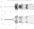
- Fig. 4 shows an initiation waveform obtained when the method for initiation under an isolated island condition is not adopted and the effective voltage output value directly increases at the rate of 5.975kV/s.
- UREF_L1, UREF_L2, and UREF L3 represent three reference waves A, B, and C, UY_LA_C, UY_LB_C, and UY_LA_C represent actual voltages generated according to the reference waves, and clearly, the waveform obtained when the method for initiation under an isolated island condition of the present application is adopted is smooth and shockless.
Landscapes
- Engineering & Computer Science (AREA)
- Power Engineering (AREA)
- Inverter Devices (AREA)
- Dc-Dc Converters (AREA)
- Supply And Distribution Of Alternating Current (AREA)
- Direct Current Feeding And Distribution (AREA)
Abstract
Description
- The present application relates to the technical field of flexible DC transmission of power systems, in particular to a method for initiating a flexible DC transmission system under an isolated island condition.
- Flexible DC transmission uses a voltage source converter to independently and rapidly control the active power and reactive power of a control system, so as to improve the stability of the system, to control the frequency and voltage fluctuation of the system and to improve the steady-state performance of a grid-connected AC system.
- There are numerous offshore islands in China, most AC grids in these islands are weak, and the power output is unstable. The flexible DC transmission has great advantages in the fields of distributed power-generation grid connection, isolated-island power supply, new-energy grid connection, urban-distribution network power supply, and so on. For this reason, the State Grid Corporation of China and the China Southern Power grid Corporation vigorously promote power grid construction in the offshore islands, wherein the State Grid Corporation of China has established the five-terminal flexible DC project in Zhoushan, Zhejiang Province, and the China Southern Power grid Corporation has established the three-terminal flexible DC project in Nanao, Guangdong Province. When no AC power supply is present in AC grid regions connected to flexible DC converter stations, the flexible DC converter stations need to initiate and operate in an isolated island mode. That is to say, the flexible DC converter stations need to initiate in the isolated island mode if not operating during the power loss of island AC grids. Methods for switching flexible DC systems to island control in the case of power loss of the AC grids during operation of the flexible DC systems have been expounded in most existing documents. For instance, Research on Switching Time Between AC-DC Parallel and Island Operation of VSC-HVDC Transmission System (Wen an, Shi Wenbo, Annual Conference of the Chinese Society of Electrical Engineering, 2014) introduces switching of a sending-end converter station from constant-active power control to constant-frequency control when the system is switched to island operation from AC-DC parallel operation, analyzes the influence of the switching duration of control strategies on the frequency of a sending-end system. Generalized Control Strategy for Grid-connected and Island Operation of VSC-HVDC System (Guan Minyuan, Zhang Jing, Power System Automation, 2015) introduces droop control of the frequency-active power of an AC side and droop control of the active power-DC voltage of a DC side, and puts forward a universal control strategy for grid-connected and island operation of a VSC-HVDC system. A control method during initiation under an isolated island condition is involved in none of the existing documents disclosed.
- Therefore, it is necessary to seek out a method for non-disturbance and shockless initiation suitable for island control to realize passive initiation of flexible DC systems during the power loss of the island AC grids
- The objective of the present application is to overcome shortcomings of the prior art by providing a method for initiating a flexible DC transmission system under an isolated island condition. The method can avoid large disturbances and big shocks during initiation under an isolated island condition and can effectively inhibit high-frequency components and distortions of output voltages and currents in an initial segment of zero-voltage initiation, thereby guaranteeing stable operation of the system.
- The technical solution adopted by the present application to fulfill the above-mentioned objective is as follows:
A method for initiating a flexible DC transmission system under an isolated island condition is implemented as follows: in an isolated island control mode, zero-voltage initiation is performed through open-loop control first, and then dual closed-loop control is adopted; or the dual closed-loop control is adopted directly; with regard to the dual closed-loop control, an outer loop controls the amplitude and frequency of an output voltage, and an inner loop controls an output current, so that a steady-state voltage is obtained; the amplitude of a voltage reference wave generated by a flexible DC control system is in a segmented mode and is divided into at least two segments, wherein a first segment of a reference wave amplitude begins at zero or a fixed value Ux and rapidly increases to Ua kV at a rate of αkV/s, latter segments of the reference wave amplitude increase at identical or different rates which are not greater than the rate α of the first segment, and the last segment of the reference wave amplitude finally increases to a rated voltage of UN kV, so that non-disturbance and shockless initiation of a flexible DC transmission system under an isolated island condition is fulfilled; wherein an initial value of a reference wave meets Ux≤0.4p.u, and the rate of the first segment meets α≥2.0p.u/s. After the voltage increases to Ua in a first segment, Ua is used as an initial value of the voltage reference wave in a second segment; after the voltage increases to Ub in the second segment, Ub is used as an initial value of the reference wave in a third segment; and Ux≤Ua≤Ub≤......≤UN, and 1.0p.u=UNkV. - According to the method for initiating a flexible DC transmission system under an isolated island condition, a voltage increase rate in the first segment is greater than or equal to a voltage increase rate in the second segment, the third segment, and the Nth segment, namely α≥β≥0, α≥γ≥0, α≥ε≥0kV/s; and meanwhile, as required, α≥20 p.u /s, and 1.0 p.u =UNkV. β is the voltage increase rate in the second segment, γ is the voltage increase rate in the third segment, and ε is the voltage increase rate in the Nth segment.
- According to the method for initiating a flexible DC transmission system under an isolated island condition, an initial value of a reference wave of a control and protection system meets urefi≤0.4p.u, namely an initial voltage meets Ux≤0.4p.u, and 1.0p.u=UNkV, so that a transformer has a low excitation surge current when charged in an initial segment to prevent protection malfunction.
- According to the method for initiating a flexible DC transmission system under an isolated island condition, the number of the segments of a voltage reference wave output meets N≥2.
- According to the method for initiating a flexible DC transmission system under an isolated island condition, during zero-voltage initiation, on-load initiation or off-load initiation is fulfilled.
- By adopting the above-mentioned solution, the present application has the following beneficial effects:
- (1) The method for initiating a flexible DC transmission system under an isolated island condition of the present application avoids shocks and disturbances during initiation under the isolated island condition;
- (2) The method for initiating a flexible DC transmission system under an isolated island condition of the present application avoids high-frequency components and distortions in the initial segment during the initiation under the isolated island condition; and
- (3) The method for initiating a flexible DC transmission system under an isolated island condition of the present application realizes passive initiation of flexible DC systems during power loss of island AC grids.
-
-
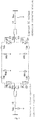
Fig. 1 is a diagram of a flexible DC transmission system having two ends; -
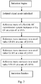
Fig. 2 is a flowchart of initiation performed through closed-loop control under an isolated island condition; -
Fig. 3 is an initiation waveform obtained through a method for initiation under an isolated island condition of the present application; -
Fig. 4 is an initiation waveform of a voltage amplitude, increasing from 0 at a rate of 5.975kV/s, of a reference wave during the initiation under the isolated island condition. - The technical solution of the present application is expounded as follows in combination of the accompanying drawings and embodiments. A flexible DC transmission system shown in
Fig. 1 is initiated under an isolated island condition through steps shown inFig. 2 , and a reference wave output during initiation under an isolated island condition includes two segments, namely N=2. - (1) After a converter station is unlocked in an isolated island mode, a voltage reference wave is initiated from 0kv, and meanwhile, a rated voltage is assumed to 119.5kV; and when an output voltage reference wave is too small, the error and harmonic content of a sampled voltage and current are prevented from being too high, which may otherwise cause an adverse effect on a control system;
- (2) A first segment is initiated, wherein in this segment an increase rate of a voltage reference wave amplitude is set as 1195kV/s, and α=1195;
- (3) When an effective voltage output value is 23.9kV, a second segment is initialized, wherein in this segment, the increase rate is converted from 1195kV/s to 5.975kV/s, and β=5.975; and
- (4) The effective voltage output value slowly increases to the rated voltage of 119.5kV from 23.9kV.
-
Fig. 3 shows a waveform obtained when a method for initiation under an isolated island condition of the present application is adopted;Fig. 4 shows an initiation waveform obtained when the method for initiation under an isolated island condition is not adopted and the effective voltage output value directly increases at the rate of 5.975kV/s. InFig. 3 andFig. 4 , UREF_L1, UREF_L2, and UREF L3 represent three reference waves A, B, and C, UY_LA_C, UY_LB_C, and UY_LA_C represent actual voltages generated according to the reference waves, and clearly, the waveform obtained when the method for initiation under an isolated island condition of the present application is adopted is smooth and shockless. - The above embodiments are only used for explaining the technical idea of the present application, and are not used for limiting the protection scope of the present application. All changes made on the basis of the technical solution according to the technical idea put forward by the present application should also fall within the protection scope of the present application.
Claims (5)
- A method for initiating a flexible DC transmission system under an isolated island condition, being implemented as follows: in an isolated island control mode, zero-voltage initiation is performed through open-loop control first, and then dual closed-loop control is adopted; or the dual closed-loop control is adopted directly; with regard to the dual closed-loop control, an outer loop controls an amplitude and frequency of an output voltage, and an inner loop controls an output current, so that a steady-state voltage is obtained; wherein an amplitude of a voltage reference wave generated by a flexible DC control system is in a segmented mode and is divided into at least two segments; a first segment of the amplitude of the voltage reference wave begins at zero or a fixed value Ux kV and increases to Ua kV at a rate of αkV/s, and a last segment of the amplitude of the voltage reference wave increases to a rated voltage of UN kV;
wherein, an initial value of the voltage reference wave meets Ux ≤ 0.4p.u, and the rate of the first segment meets α ≥ 2.0p.u/s; and
after the voltage increases to Ua kV in a first segment, Ua kV is used as an initial value of the voltage reference wave in a second segment; after the voltage increases to Ub kV in the second segment, Ub kV is used as an initial value of the reference wave in a third segment; and Ux ≤ Ua ≤ Ub≤......≤ UN, and UN kV=1.0p.u. - The method for initiating a flexible DC transmission system under an isolated island condition according to Claim 1, wherein a voltage increase rate in the first segment is greater than or equal to a voltage increase rate in the second segment, the third segment, ......, and an Nth segment, namely α ≥ β ≥ 0, α ≥ γ ≥ 0, α ≥ ε ≥ 0 kV/s, β is the voltage increase rate in the second segment, γ is the voltage increase rate in the third segment, and ε is the voltage increase rate in the Nth segment.
- The method for initiating a flexible DC transmission system under an isolated island condition according to Claim 1, wherein in an initial segment of initiation under an isolated island condition, a relation between a magnetic flux φi and the voltage of the transformer meets the following formula:


if Ux ≤ 0.5UN, a maximum magnetic flux generated does not exceed the rated magnetic flux. - The method for initiating a flexible DC transmission system under an isolated island condition according to Claim 1, wherein the number of the segments of a voltage reference wave output meets N ≥ 2.
- The method for initiating a flexible DC transmission system under an isolated island condition according to Claim 1, wherein during initiation under an isolated island condition, on-load initiation or off-load initiation is fulfilled.
Applications Claiming Priority (2)
| Application Number | Priority Date | Filing Date | Title |
|---|---|---|---|
| CN201710286180.8A CN106953349B (en) | 2017-04-27 | 2017-04-27 | A method for island start-up of flexible DC transmission system |
| PCT/CN2018/084716 WO2018196830A1 (en) | 2017-04-27 | 2018-04-27 | Method for initiating flexible dc transmission system under isolated island condition |
Publications (2)
| Publication Number | Publication Date |
|---|---|
| EP3618215A1 true EP3618215A1 (en) | 2020-03-04 |
| EP3618215A4 EP3618215A4 (en) | 2020-05-06 |
Family
ID=59476786
Family Applications (1)
| Application Number | Title | Priority Date | Filing Date |
|---|---|---|---|
| EP18790888.4A Pending EP3618215A4 (en) | 2017-04-27 | 2018-04-27 | STARTING METHOD OF FLEXIBLE DC TRANSMISSION SYSTEM IN ISOLATED ISLAND CONDITION |
Country Status (7)
| Country | Link |
|---|---|
| US (1) | US11329486B2 (en) |
| EP (1) | EP3618215A4 (en) |
| JP (1) | JP6880234B2 (en) |
| KR (1) | KR102278988B1 (en) |
| CN (1) | CN106953349B (en) |
| AU (1) | AU2018259838B2 (en) |
| WO (1) | WO2018196830A1 (en) |
Families Citing this family (13)
| Publication number | Priority date | Publication date | Assignee | Title |
|---|---|---|---|---|
| CN106953349B (en) * | 2017-04-27 | 2019-06-21 | 南京南瑞继保电气有限公司 | A method for island start-up of flexible DC transmission system |
| CN107546760A (en) * | 2017-09-12 | 2018-01-05 | 国网浙江省电力公司 | A kind of passive startup method of flexible direct current power transmission system isolated island for offshore island |
| CN107546761A (en) * | 2017-09-12 | 2018-01-05 | 国网浙江省电力公司 | A kind of method for the flexible direct current power transmission system isolated island closed-loop start-up of offshore island |
| CN110147637B (en) * | 2019-06-05 | 2020-07-31 | 厦门大学 | Rub-impact fault diagnosis method based on wavelet and harmonic component greedy sparse identification |
| CN110912091B (en) * | 2019-12-03 | 2020-11-10 | 西安交通大学 | A single-ended traveling wave ultra-high-speed protection system and method for flexible DC transmission lines |
| CN114825367B (en) * | 2021-01-19 | 2026-02-10 | 南京南瑞继保电气有限公司 | A control method for islanded operation of a flexible DC transmission system |
| MX2023007693A (en) * | 2021-01-19 | 2023-07-12 | Nr Electric Co Ltd | Control method and system for island operation of vsc-hvdc system. |
| CN113839405B (en) * | 2021-08-09 | 2023-08-08 | 山东大学 | New energy island transmission system parameter optimization method and system through flexible direct current power grid |
| CN114123286B (en) * | 2021-11-26 | 2023-06-27 | 中国三峡建工(集团)有限公司 | Flexible voltage control method for flexible direct current system |
| CN114336756B (en) * | 2022-01-07 | 2023-06-20 | 国网经济技术研究院有限公司 | A condenser configuration method and system for a new energy island DC external transmission system |
| CN114509641B (en) * | 2022-01-07 | 2025-08-19 | 西安理工大学 | Two-stage island detection method applied to direct-current micro-grid |
| CN115864540B (en) * | 2022-12-14 | 2025-08-05 | 南方电网科学研究院有限责任公司 | Energy collaborative control method, device and equipment for new energy island transmission system |
| CN117728478B (en) * | 2024-02-08 | 2024-04-19 | 四川大学 | Analysis method of harmonic transfer at line sections of parallel three-terminal DC transmission system |
Family Cites Families (18)
| Publication number | Priority date | Publication date | Assignee | Title |
|---|---|---|---|---|
| JPH1014247A (en) * | 1996-06-27 | 1998-01-16 | Toshiba Corp | Power converter |
| JP3395641B2 (en) * | 1998-04-03 | 2003-04-14 | 株式会社日立製作所 | Power converter |
| JP3700018B2 (en) * | 1999-02-26 | 2005-09-28 | 株式会社日立製作所 | Control device and method for DC power transmission equipment |
| JP4287031B2 (en) * | 2000-07-14 | 2009-07-01 | 株式会社日立製作所 | Method and apparatus for controlling self-excited DC power transmission system |
| JP4689734B2 (en) | 2009-07-06 | 2011-05-25 | 株式会社三共 | Game machine |
| EP2871759A1 (en) | 2013-11-06 | 2015-05-13 | Vestas Wind Systems A/S | A method for charging a DC link of a wind turbine power electronic converter |
| CN103647440B (en) * | 2013-11-08 | 2016-01-27 | 上海华力微电子有限公司 | A kind of soft starting circuit and comprise the DC-DC circuit of this soft starting circuit |
| WO2015090375A1 (en) | 2013-12-18 | 2015-06-25 | Abb Technology Ltd | Microgrid black-start |
| CN104134996B (en) | 2014-07-09 | 2016-01-13 | 国家电网公司 | Containing the power distribution network large-area power-cuts recovery technology of distributed power source |
| EP3026803A1 (en) * | 2014-11-25 | 2016-06-01 | Alstom Technology Ltd | Start-up of HVDC converters |
| CN104578128B (en) * | 2014-12-23 | 2017-09-29 | 南京南瑞继保电气有限公司 | A kind of flexible direct current power transmission system isolated island turns the switching method of networking |
| CN104485683B (en) * | 2014-12-23 | 2018-07-06 | 南京南瑞继保电气有限公司 | A kind of isolated island turns networking method |
| EP4125203A1 (en) | 2015-03-16 | 2023-02-01 | General Electric Technology GmbH | Start-up of hvdc networks |
| CN104821710B (en) * | 2015-04-30 | 2018-05-04 | 许继集团有限公司 | A kind of MMC-MTDC systems start control method |
| CN105743122B (en) | 2016-03-25 | 2018-09-21 | 江苏省电力公司无锡供电公司 | Island detection method suitable for cluster distributed photovoltaic system |
| CN106451458A (en) * | 2016-09-18 | 2017-02-22 | 许继集团有限公司 | Reactive control method and reactive controller for flexible direct current power transmission network |
| US20180131268A1 (en) * | 2016-10-19 | 2018-05-10 | Dynapower Company Llc | Power system and method of starting multiple power converters in grid forming mode |
| CN106953349B (en) | 2017-04-27 | 2019-06-21 | 南京南瑞继保电气有限公司 | A method for island start-up of flexible DC transmission system |
-
2017
- 2017-04-27 CN CN201710286180.8A patent/CN106953349B/en active Active
-
2018
- 2018-04-27 EP EP18790888.4A patent/EP3618215A4/en active Pending
- 2018-04-27 WO PCT/CN2018/084716 patent/WO2018196830A1/en not_active Ceased
- 2018-04-27 AU AU2018259838A patent/AU2018259838B2/en active Active
- 2018-04-27 KR KR1020197031676A patent/KR102278988B1/en active Active
- 2018-04-27 US US16/607,847 patent/US11329486B2/en active Active
- 2018-04-27 JP JP2019558665A patent/JP6880234B2/en active Active
Also Published As
| Publication number | Publication date |
|---|---|
| JP6880234B2 (en) | 2021-06-02 |
| US11329486B2 (en) | 2022-05-10 |
| US20200195013A1 (en) | 2020-06-18 |
| AU2018259838B2 (en) | 2020-12-10 |
| CN106953349B (en) | 2019-06-21 |
| JP2020518228A (en) | 2020-06-18 |
| AU2018259838A1 (en) | 2019-11-14 |
| KR20190134681A (en) | 2019-12-04 |
| EP3618215A4 (en) | 2020-05-06 |
| CN106953349A (en) | 2017-07-14 |
| WO2018196830A1 (en) | 2018-11-01 |
| KR102278988B1 (en) | 2021-07-16 |
Similar Documents
| Publication | Publication Date | Title |
|---|---|---|
| US11329486B2 (en) | Method for initiating flexible DC transmission system under isolated island condition | |
| EP3886288B1 (en) | HIGH-FREQUENCY DC TRANSMISSION SYSTEM WITH UNCONTROLLED RECTRICAL DIRECTION FOR OFFSHORE WIND FARM | |
| CN104811067B (en) | PR (proportional resonant) controller-based NMC-HVDC (modular multilevel converter-high voltage direct current) circulating current suppression method | |
| CN103973121B (en) | single-phase power electronic transformer | |
| EP4087082B1 (en) | Zero-sequence current balancer with a real power injector for a three-phase power system | |
| US10003251B2 (en) | Power converting device containing high frequency inverter and low frequency inverter connecting in parallel and the method thereof | |
| US20100109616A1 (en) | System and method for reactive power compensation and flicker management | |
| CN102570491A (en) | Multilevel power converter or inverter arrangement using h bridges | |
| Mohammed et al. | Dynamic voltage restorer (DVR) system for compensation of voltage sags, state-of-the-art review | |
| Qahraman et al. | A VSC based series hybrid converter for HVDC transmission | |
| ElGebaly et al. | Reactive power compensation by multilevel inverter STATCOM for railways power grid | |
| US10326275B2 (en) | Method for controlling zero sequence voltage of voltage source converter | |
| CN110224622A (en) | Bridge-type modular multi-level converter submodule capacitor voltage fluctuates suppressing method | |
| EP4418520A1 (en) | Power conversion system | |
| Liu et al. | Control of single-stage AC-AC solid state transformer for power exchange between grids | |
| Xu et al. | Multilevel-converter-based VSC transmission operating under fault AC conditions | |
| CN107658905A (en) | A kind of fault ride-through of power grid system and method based on double-fed fan motor field | |
| Xi et al. | STATCOM operation strategy under power system faults | |
| CN103084724A (en) | Contravariant accelerating power supply device of electron beam depositing equipment and control method thereof | |
| Zhang et al. | A three-Phase five-level unidirectional rectifier with reduced components | |
| CN100362720C (en) | Active Superconducting DC Current Limiter | |
| Zheng et al. | A novel soft-start method for SVG based on D-axis orientation | |
| Amari et al. | A novel method to mitigate commutation failures in lcc-hvdc system connected to a weak ac network | |
| CN105610309A (en) | Large-power rectifier using direct current injection method in DC side | |
| Dong et al. | Peak Current Control of Dual Active Full-Bridge Based on Extended Phase Shift Control |
Legal Events
| Date | Code | Title | Description |
|---|---|---|---|
| STAA | Information on the status of an ep patent application or granted ep patent |
Free format text: STATUS: THE INTERNATIONAL PUBLICATION HAS BEEN MADE |
|
| PUAI | Public reference made under article 153(3) epc to a published international application that has entered the european phase |
Free format text: ORIGINAL CODE: 0009012 |
|
| STAA | Information on the status of an ep patent application or granted ep patent |
Free format text: STATUS: REQUEST FOR EXAMINATION WAS MADE |
|
| 17P | Request for examination filed |
Effective date: 20191104 |
|
| AK | Designated contracting states |
Kind code of ref document: A1 Designated state(s): AL AT BE BG CH CY CZ DE DK EE ES FI FR GB GR HR HU IE IS IT LI LT LU LV MC MK MT NL NO PL PT RO RS SE SI SK SM TR |
|
| AX | Request for extension of the european patent |
Extension state: BA ME |
|
| A4 | Supplementary search report drawn up and despatched |
Effective date: 20200402 |
|
| RIC1 | Information provided on ipc code assigned before grant |
Ipc: H02J 3/36 20060101AFI20200328BHEP Ipc: H02J 3/38 20060101ALI20200328BHEP |
|
| DAV | Request for validation of the european patent (deleted) | ||
| DAX | Request for extension of the european patent (deleted) | ||
| STAA | Information on the status of an ep patent application or granted ep patent |
Free format text: STATUS: EXAMINATION IS IN PROGRESS |
|
| 17Q | First examination report despatched |
Effective date: 20210811 |
|
| RAP3 | Party data changed (applicant data changed or rights of an application transferred) |
Owner name: NR ENGINEERING CO., LTD Owner name: NR ELECTRIC CO., LTD |