EP3618140B1 - Battery storage system with secure access - Google Patents
Battery storage system with secure access Download PDFInfo
- Publication number
- EP3618140B1 EP3618140B1 EP18191855.8A EP18191855A EP3618140B1 EP 3618140 B1 EP3618140 B1 EP 3618140B1 EP 18191855 A EP18191855 A EP 18191855A EP 3618140 B1 EP3618140 B1 EP 3618140B1
- Authority
- EP
- European Patent Office
- Prior art keywords
- disconnector
- key
- storage system
- compartment
- energy source
- Prior art date
- Legal status (The legal status is an assumption and is not a legal conclusion. Google has not performed a legal analysis and makes no representation as to the accuracy of the status listed.)
- Active
Links
Images

Classifications
-
- H—ELECTRICITY
- H01—ELECTRIC ELEMENTS
- H01M—PROCESSES OR MEANS, e.g. BATTERIES, FOR THE DIRECT CONVERSION OF CHEMICAL ENERGY INTO ELECTRICAL ENERGY
- H01M50/00—Constructional details or processes of manufacture of the non-active parts of electrochemical cells other than fuel cells, e.g. hybrid cells
- H01M50/20—Mountings; Secondary casings or frames; Racks, modules or packs; Suspension devices; Shock absorbers; Transport or carrying devices; Holders
- H01M50/262—Mountings; Secondary casings or frames; Racks, modules or packs; Suspension devices; Shock absorbers; Transport or carrying devices; Holders with fastening means, e.g. locks
-
- H—ELECTRICITY
- H01—ELECTRIC ELEMENTS
- H01M—PROCESSES OR MEANS, e.g. BATTERIES, FOR THE DIRECT CONVERSION OF CHEMICAL ENERGY INTO ELECTRICAL ENERGY
- H01M10/00—Secondary cells; Manufacture thereof
- H01M10/42—Methods or arrangements for servicing or maintenance of secondary cells or secondary half-cells
-
- B—PERFORMING OPERATIONS; TRANSPORTING
- B60—VEHICLES IN GENERAL
- B60L—PROPULSION OF ELECTRICALLY-PROPELLED VEHICLES; SUPPLYING ELECTRIC POWER FOR AUXILIARY EQUIPMENT OF ELECTRICALLY-PROPELLED VEHICLES; ELECTRODYNAMIC BRAKE SYSTEMS FOR VEHICLES IN GENERAL; MAGNETIC SUSPENSION OR LEVITATION FOR VEHICLES; MONITORING OPERATING VARIABLES OF ELECTRICALLY-PROPELLED VEHICLES; ELECTRIC SAFETY DEVICES FOR ELECTRICALLY-PROPELLED VEHICLES
- B60L3/00—Electric devices on electrically-propelled vehicles for safety purposes; Monitoring operating variables, e.g. speed, deceleration or energy consumption
-
- B—PERFORMING OPERATIONS; TRANSPORTING
- B60—VEHICLES IN GENERAL
- B60L—PROPULSION OF ELECTRICALLY-PROPELLED VEHICLES; SUPPLYING ELECTRIC POWER FOR AUXILIARY EQUIPMENT OF ELECTRICALLY-PROPELLED VEHICLES; ELECTRODYNAMIC BRAKE SYSTEMS FOR VEHICLES IN GENERAL; MAGNETIC SUSPENSION OR LEVITATION FOR VEHICLES; MONITORING OPERATING VARIABLES OF ELECTRICALLY-PROPELLED VEHICLES; ELECTRIC SAFETY DEVICES FOR ELECTRICALLY-PROPELLED VEHICLES
- B60L50/00—Electric propulsion with power supplied within the vehicle
- B60L50/50—Electric propulsion with power supplied within the vehicle using propulsion power supplied by batteries or fuel cells
- B60L50/60—Electric propulsion with power supplied within the vehicle using propulsion power supplied by batteries or fuel cells using power supplied by batteries
- B60L50/64—Constructional details of batteries specially adapted for electric vehicles
-
- H—ELECTRICITY
- H01—ELECTRIC ELEMENTS
- H01H—ELECTRIC SWITCHES; RELAYS; SELECTORS; EMERGENCY PROTECTIVE DEVICES
- H01H9/00—Details of switching devices, not covered by groups H01H1/00 - H01H7/00
- H01H9/20—Interlocking, locking, or latching mechanisms
- H01H9/22—Interlocking, locking, or latching mechanisms for interlocking between casing, cover, or protective shutter and mechanism for operating contacts
-
- H—ELECTRICITY
- H01—ELECTRIC ELEMENTS
- H01M—PROCESSES OR MEANS, e.g. BATTERIES, FOR THE DIRECT CONVERSION OF CHEMICAL ENERGY INTO ELECTRICAL ENERGY
- H01M50/00—Constructional details or processes of manufacture of the non-active parts of electrochemical cells other than fuel cells, e.g. hybrid cells
- H01M50/20—Mountings; Secondary casings or frames; Racks, modules or packs; Suspension devices; Shock absorbers; Transport or carrying devices; Holders
- H01M50/204—Racks, modules or packs for multiple batteries or multiple cells
-
- H—ELECTRICITY
- H01—ELECTRIC ELEMENTS
- H01M—PROCESSES OR MEANS, e.g. BATTERIES, FOR THE DIRECT CONVERSION OF CHEMICAL ENERGY INTO ELECTRICAL ENERGY
- H01M50/00—Constructional details or processes of manufacture of the non-active parts of electrochemical cells other than fuel cells, e.g. hybrid cells
- H01M50/20—Mountings; Secondary casings or frames; Racks, modules or packs; Suspension devices; Shock absorbers; Transport or carrying devices; Holders
- H01M50/271—Lids or covers for the racks or secondary casings
-
- B—PERFORMING OPERATIONS; TRANSPORTING
- B60—VEHICLES IN GENERAL
- B60L—PROPULSION OF ELECTRICALLY-PROPELLED VEHICLES; SUPPLYING ELECTRIC POWER FOR AUXILIARY EQUIPMENT OF ELECTRICALLY-PROPELLED VEHICLES; ELECTRODYNAMIC BRAKE SYSTEMS FOR VEHICLES IN GENERAL; MAGNETIC SUSPENSION OR LEVITATION FOR VEHICLES; MONITORING OPERATING VARIABLES OF ELECTRICALLY-PROPELLED VEHICLES; ELECTRIC SAFETY DEVICES FOR ELECTRICALLY-PROPELLED VEHICLES
- B60L2200/00—Type of vehicles
- B60L2200/26—Rail vehicles
-
- B—PERFORMING OPERATIONS; TRANSPORTING
- B60—VEHICLES IN GENERAL
- B60L—PROPULSION OF ELECTRICALLY-PROPELLED VEHICLES; SUPPLYING ELECTRIC POWER FOR AUXILIARY EQUIPMENT OF ELECTRICALLY-PROPELLED VEHICLES; ELECTRODYNAMIC BRAKE SYSTEMS FOR VEHICLES IN GENERAL; MAGNETIC SUSPENSION OR LEVITATION FOR VEHICLES; MONITORING OPERATING VARIABLES OF ELECTRICALLY-PROPELLED VEHICLES; ELECTRIC SAFETY DEVICES FOR ELECTRICALLY-PROPELLED VEHICLES
- B60L2270/00—Problem solutions or means not otherwise provided for
- B60L2270/40—Problem solutions or means not otherwise provided for related to technical updates when adding new parts or software
-
- Y—GENERAL TAGGING OF NEW TECHNOLOGICAL DEVELOPMENTS; GENERAL TAGGING OF CROSS-SECTIONAL TECHNOLOGIES SPANNING OVER SEVERAL SECTIONS OF THE IPC; TECHNICAL SUBJECTS COVERED BY FORMER USPC CROSS-REFERENCE ART COLLECTIONS [XRACs] AND DIGESTS
- Y02—TECHNOLOGIES OR APPLICATIONS FOR MITIGATION OR ADAPTATION AGAINST CLIMATE CHANGE
- Y02E—REDUCTION OF GREENHOUSE GAS [GHG] EMISSIONS, RELATED TO ENERGY GENERATION, TRANSMISSION OR DISTRIBUTION
- Y02E60/00—Enabling technologies; Technologies with a potential or indirect contribution to GHG emissions mitigation
- Y02E60/10—Energy storage using batteries
-
- Y—GENERAL TAGGING OF NEW TECHNOLOGICAL DEVELOPMENTS; GENERAL TAGGING OF CROSS-SECTIONAL TECHNOLOGIES SPANNING OVER SEVERAL SECTIONS OF THE IPC; TECHNICAL SUBJECTS COVERED BY FORMER USPC CROSS-REFERENCE ART COLLECTIONS [XRACs] AND DIGESTS
- Y02—TECHNOLOGIES OR APPLICATIONS FOR MITIGATION OR ADAPTATION AGAINST CLIMATE CHANGE
- Y02T—CLIMATE CHANGE MITIGATION TECHNOLOGIES RELATED TO TRANSPORTATION
- Y02T10/00—Road transport of goods or passengers
- Y02T10/60—Other road transportation technologies with climate change mitigation effect
- Y02T10/70—Energy storage systems for electromobility, e.g. batteries
Definitions
- the invention relates to a battery storage system and a transportation vehicle with such a battery storage system.
- Electric batteries which are usually composed of a plurality of battery cells, are increasingly used in transportation applications. Due to the high power and energy of the battery storage system in such applications, it may be beneficial to add auxiliary electrical components to the battery cells to increase performance, lifetime, and safety of the battery storage system.
- Typical auxiliary electrical components which are added to the battery cells, are, for example, contactors, disconnectors, fuses, current and voltage sensors and/or control boards. In many cases, such electrical components may have a lower lifetime than the battery cells themselves. As an example, when a fuse is activated due to an external short-circuit event, the fuse may need to be replaced in order to take the battery storage system back to operation.
- CN 105 788 913 A relates to an electric train with batteries, with a locking system comprising several keys and door locks for improving the safety for service personal.
- a key for a drivers control room a door for a compartment with a traction battery disconnector can be opened.
- a key used for locking the traction battery disconnector and a further key for locking a system grounding switch can be used together for unlocking a security key box, in which further keys for high voltage equipment cabinet doors are locked.
- GB 2 107 527 A describes a transformer take-off cabinet, which has a door and an openable roof. The roof is locked by a lock and a key for the lock is provided in a repository, which only can be opened, when removable parts of load break connectors are removed.
- a battery storage system may comprise a plurality of electrically interconnected battery cells and further electric equipment for charging, discharging and/or controlling the battery cells.
- the battery storage system may be designed for high-power applications, such as transportation and/or power quality.
- high power may refer to currents of more than 10 A and/or voltages of more than 60 V.
- the battery storage system comprises a battery compartment, an electrical component compartment, a first disconnector compartment and optionally a second disconnector compartment. All these compartments may be mechanically interconnected and/or may have a common frame. They all may be provided as separated parts of a cabinet.
- Each compartment may be accessible by a separate door, which prevents access to the components in the interior of the compartment, in particular, when they are on potential. When the respective door is closed, the components in each compartment may be protected from being touched by a person.
- a locking system of one or more mechanical locks is implemented, which may solely allow to access the compartments in a specific sequence to reduce electrical risks for service personnel.
- the battery compartment accommodates a plurality of battery cells. These battery cells may be electrically connected in series and/or in parallel and may store the electrical energy provided by the battery storage system.
- accommodated may mean that the battery cells are mechanically connected to the interior of the compartment.
- the electrical component compartment accommodates electrical components electrically connectable with the battery cells.
- the battery cells may be connected to electrical components such as fuses, connectors, etc.
- the electrical components in the electrical component compartment may comprise components that may have to be maintained and/or exchanged more often than the battery cells.
- the disconnector compartment accommodates a disconnector for electrically connecting the electrical components to an electrical energy source in a closed position and for electrically disconnecting the electrical components from the energy source in an opened position.
- the energy source may be the battery cells or may be an external electrical energy source, such as an electrical grid.
- the disconnector may be a mechanical switch, which manually may be moved from the opened to the closed position and vice versa. It may be that the disconnector connects and disconnects two or more lines.
- the electrical component compartment comprises a door for accessing the electrical components, wherein the door comprises a lock openable and closable by a key. Furthermore, the disconnector compartment accommodates a locking mechanism for releasing the key, when the disconnector is in the opened position.
- the electrical components are disconnected from the energy source, before the door for accessing the electrical components can be opened.
- a service technician is forced to open the disconnector, before he can use the key to open the electrical components compartment.
- the battery storage system may be serviced, in particular, by replacing protection devices such as contactors or fuses, with minimum electrical risks to service personnel.
- the battery storage system is decomposed into several compartments, with at least one compartment for the battery cells, a compartment for electrical components, such as fuses, contactors, charging resistors, and a disconnector compartment with a disconnector to electrically connect or disconnect the electrical components from an energy source.
- auxiliary components may be performed without electrical risks to service personnel.
- service personnel does not need to wear gloves or other protective clothing against voltage.
- servicing of the battery storage system may be performed faster and easier. In particular, service personnel does not need to be trained for working while exposed to dangerous voltages.
- components which cause pollution may be separated from components which are sensitive to pollution, such as battery modules. In such a way, the battery compartment may be kept clean. Battery cells and/or battery modules may be designed for lower pollution degree, thus smaller and lighter.
- the key is solely removable from the locking mechanism, when the disconnector is in the opened position.
- the key is not removable from the locking mechanism, when the disconnector is in the closed position. In such a way, a service technician has to disconnect the electrical components from the energy source, before he can remove the key from the locking mechanism.
- the key is solely removable from the lock, when the door of the compartment is closed. In this case, it may be even not possible that the service technician reconnects the electrical components, before the door is closed.
- the disconnector has a lever, which is solely movable from the closed position into the opened position, when the key is inserted into the locking mechanism.
- the service technician may move the disconnector with the lever into the opened position. Then he may take the key and open the electrical component compartment.
- the lever is solely movable from the opened position into the closed position, when the key is inserted into the locking mechanism.
- the service technician needs the key for inserting it into the locking mechanism, such that he can move the lever into the closed position. In such a way, he is reminded to close the door of the electrical component compartment.
- the locking mechanism is a lock for a lever of the disconnector.
- the lock may be designed, such that the lever only can be moved, when the key is inserted into the lock.
- the key is solely removable from the lock, when the lever is in the opened position.
- the lock furthermore may be designed, such that it retains the key, when the lever is in the closed position and/or in positions between the opened position and the closed position.
- the locking mechanism comprises a hatch, which is solely openable, when a lever of the disconnector is in the opened position.
- the handle of the lever In the closed position, the handle of the lever may protrude over the hatch, such that then opening of the hatch is prevented.
- the key may be accommodated behind the hatch. Thus, the key only may be removed from the space behind the hatch, when the lever has been turned into the opened position.
- the hatch has a lock, which is solely accessible, when the hatch is opened, wherein the hatch is solely closable, when the key is in the lock of the hatch.
- the opened hatch prevents the lever of the disconnector to be moved into the closed position.
- the opened hatch may be positioned besides the lever, such that a handle of the lever is blocked by the opened hatch. This also reminds a service technician to close the door of the electrical components compartment.
- the energy source are the battery cells.
- an external energy source such as a catenary line
- the energy source is an external energy source, for example the output of a converter interfacing to an external grid. It also may be possible that the battery storage system is disconnected from the external energy source and such that the battery cells are disconnected from the electrical components in another way.
- the battery compartment comprises a door for accessing the battery cells, wherein the door comprises a lock openable and closable by the key.
- the battery compartment may be accessible with the same key, with which the electrical component compartment may be opened.
- the key may be solely removable from the lock, when the door of the battery compartment is closed.
- the electrical components in the electrical component compartment comprises at least one of: a fuse, a connector, a control board, a voltage and/or current measurement device.
- the electrical components may be or may comprise components, which need service, maintenance more often as the battery cells.
- the battery storage system may have two disconnector compartments.
- One disconnector may be used for disconnecting the battery cells from the electrical components.
- Another disconnector may be used for disconnecting an external energy source from the electrical components.
- the disconnector compartment mentioned above may be seen as a first disconnector compartment, its disconnector as a first disconnector and its key as a first key.
- the battery storage system further comprises a second disconnector compartment accommodating a second disconnector for electrically connecting the electrical components to a second energy source in a closed SY position and for electrically disconnecting the electrical components from a second energy source in an opened position.
- the second disconnector may be designed like the first disconnector.
- the first disconnector compartment comprises a door for accessing the first disconnector, wherein the door of the first disconnector compartment comprises a lock openable and closable by a second key.
- the second disconnector compartment may accommodate a second locking mechanism for releasing the second key, when the second disconnector is in the opened position.
- the first disconnector compartment can be opened and/or closed like the electrical component compartment.
- a second key may be provided in the second disconnector compartment, like the first key in the first disconnector compartment.
- the second locking mechanism may be designed like the first locking mechanism.
- the first energy source are the battery cells and the second energy source is an external energy source. It may be that the battery cells are disconnected from the electrical components in a first step and that the external energy source is disconnected from the electrical components in a second step.
- the order of the steps may be forced by the locking system with the two keys and the two locking mechanisms.
- the first energy source is an external energy source and the second energy source are the battery cells. It also may be that the external energy source is disconnected from the electrical components in a first step and that the battery cells are disconnected from the electrical components in a second step. Again, the order of the steps may be forced by the locking system with the two keys and the two locking mechanisms.
- a further aspect of the invention relates to a transportation vehicle, such as an electric car, an electric bus, an electric tram and/or an electric railway vehicle, which comprises a battery storage system as described above and below.
- the battery storage system may be integrated in the transportation vehicle.
- the transportation vehicle comprises a drivetrain, such as one or more electrical motors, suppliable by the battery storage system.
- the transportation vehicle may be supplied by the battery energy storage system, when no power from an external power source, such as a catenary line, is present.
- the transportation vehicle is suppliable from an electrical grid as energy source during operation of the drive.
- an electrical grid for example, a train, tram or bus as transportation vehicle may be supplied from an electrical grid, for example via a catenary line.
- the battery storage system may be charged during operation of the drive.
- the transportation vehicle also may be hybrid train that additionally has a fuel powered engine.
- the battery storage system may be charged during braking.
- subsystems of the battery storage system such as the battery cells and the electrical components, may be integrated in separate compartments, which can be accessed by separate doors.
- an access and/or locking system it is only possible to access potentially dangerous compartments, such as the electrical component compartment with parts for regular service, after it has been disconnected from the subsystem with the battery cells and optionally after external connections to an external energy source have been either disconnected or grounded.
- the access system may be implemented by a series of locks and keys, where keys are released only after some required action has been performed.
- the access system may also prevent service personnel from connecting the electrical components back to a dangerous voltage before the electrical component compartment has been closed and thereby is protected from contact by service personnel.
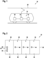
- Fig. 1 shows a transportation vehicle 10 in the form of a railway vehicle.
- the transportation vehicle 10 also may be a street vehicle, such as a bus.
- the railway vehicle such as a train or tram, comprises a drivetrain 12 with an electrical motor 14, which drives a wheel of the transportation vehicle 10.
- the drivetrain 12 furthermore comprises an electrical converter 16, which is adapted for generating an AC current supplied to the electrical motor 14.
- the converter 16 may be powered from a battery storage system 18 and/or an external electrical energy source 20, such as a catenary line of an AC or DC grid.
- the battery storage system 18 is charged from the external energy source 20 and is then used, when no external energy source 20 is viable, which may be the case at specific sections of the railways. It also may be that the battery storage system 18 is charged during operation of the drivetrain 12 and the electrical motor 14 and/or that the battery storage system 18 supports the external energy source 20, dependent on the availability of power from the extern energy source 20.
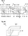
- Fig. 2 shows a front view of a cabinet 22 housing the battery storage system 18.
- the cabinet 22 comprises four compartments, i.e. a battery compartment 24, an electrical component compartment 26 and two disconnector compartments 28, 30.
- the battery storage system 18 has a locking system 32, which comprises several keys and locks.
- a locking system 32 which comprises several keys and locks.
- Fig. 2 it is shown that every compartment 24, 26, 28, 30 has a door 34, 36, 38, 40 with a lock 44, 46, 48, 50.
- a key 42 of the locking system 32 is shown, which may be kept outside of the compartments 24, 26, 28, 30. Further keys of the locking system 32 are provided inside the compartments, as will be explained with respect to Fig. 3 .
- the key 42 and the lock 48 are optional. It also may be that the disconnector compartment 28 has a door 34, which may be opened and closed without a key.
- Fig. 3 schematically shows the interior of the cabinet 22.
- the battery compartment 24 comprises a plurality of battery cells 52, which are used as power storage of the battery storage system 18. As shown, the battery cells 52, which may be assembled into modules, may be connected in series. However, also other connections are possible.
- the battery compartment 24 furthermore may comprise a control and/or measurement device 54, which, for example, measures and controls voltages across the battery cells 52.
- the disconnector compartment 30 comprises a disconnector 56, which may be a mechanical switch adapted for disconnecting and connecting a power line 70 between the battery compartment 24 and the electrical component compartment 26.
- the disconnector 56 may be operated manually with a lever 58.
- the disconnector 56 and/or the lever 58 may be moved between an opened position and a closed position. Furthermore, a locking mechanism 60, such as a lock, and a key 62 are provided in the disconnector compartment 30.
- the electrical component compartment 26 comprises electrical components 64, which have to be maintained and/or serviced more often as the battery cells 52.
- the electrical components may comprise fuses 64a, electrical connectors 64b, a recharging resistor 64c and sensors 64d.
- the electrical component compartment 26 furthermore may comprise a control and/or measurement device 68, which, for example, processes signals from the sensors 64d and/or controls the electrical connectors 64b.
- the electrical components 64 may be connected via a power line 70 with the battery cells 52.
- the disconnector 56 may be adapted for disconnecting the power line 70.
- the control and/or measurement devices 54, 68 may be connected with a signal line 72. It has to be noted that the signal line 72 may or may not be interrupted by the disconnector 56. In the latter case, sufficient insulation may need to be applied to the measurement devices 54 so that the control and/or measurement device 68 is insulated from dangerous voltages.
- the disconnector compartment 28 comprises a disconnector 74, which may be a mechanical switch adapted for disconnecting and connecting a power line 76 between an external energy source 20 and the electrical component compartment 26.
- the disconnector 74 may be operated manually with a lever 78.
- the disconnector 74 and/or the lever 78 may be moved between an opened position and a closed position. Furthermore, a locking mechanism 80, such as a lock, and a key 82 are provided in the disconnector compartment 28.
- the control and/or measurement device 68 may be connected with a signal line 84 to an outside of the battery storage system 18. It has to be noted that the signal line 84 may be guided through the disconnector compartment 28 and/or that the disconnector 74 may not interrupt the signal line 84.
- a controlled access sequence or access method may be performed by a service technician, which may establish a mistake-proof servicing concept.
- the first key 42 allows opening of the disconnector compartment 28 by opening the lock 48 of the door 38.
- the battery storage system 18, and in particular the electrical components 64 may be disconnected from the external energy source 20 with the disconnector 74.
- the locking mechanism 80 mechanically interconnected with the disconnector 74 releases the second key 82, when the disconnector 74 has been moved into the opened position.
- the look 50 of the door 40 of the disconnector compartment 30 can be opened.
- the battery cells 52 then may be disconnected from the external energy source 20 with the disconnector 56.
- the locking mechanism 60 mechanically interconnected with the disconnector 74 releases then the third key 62, when the disconnector 56 has been moved into the opened position.
- the third key 62 allows opening the electrical component compartment 26 by opening the lock 46 of the door 46? and optionally allows opening the battery compartment 24 by opening the lock 44 of the door 34.
- the locking mechanisms 60, 80 may prevent that disconnectors 56, 74 may be moved into the closed position, when the corresponding keys 62, 82 are put back into the release mechanism.
- Performing the above steps in reverse order may allow taking the battery storage system 18 safely back into operation.
- the order in which the disconnector compartments 28, 30 are opened are exchanged.
- the lock 50 of the disconnector compartment 30 may be opened with the first key 42.
- the key 62 is the second key.
- the second key 62 then may be released, when the disconnector 56 is moved in the opened position.
- the lock 48 of the disconnector compartment 28 may be opened with the second key 62.
- the third key 82 then may be released, when the disconnector 74 is moved in the opened position.
- the lock 46 of the door 36 of the electrical component compartment 26 then may be opened with the third key 82.
- the locks 44, 46, 48, 50 are designed such that the corresponding keys 42, 62, 82 only may be removed from the lock, when the corresponding door is closed and/or locked. In particular, this may be the case for the lock 46 of the electrical component compartment 26 and/or the lock 44 of the battery compartment 24.
- the disconnectors 56, 74 and the locking mechanisms 60, 80 both may be designed equally. Only the keys 62, 82 released by the specific locking mechanisms 60, 80 may be different.
- the keys 62, 82 may be solely removable from the locking mechanisms 60, 80, when the disconnectors 56, 74 are in the opened position.
- the levers 58, 78 of the disconnectors 56, 74 may be solely movable from the closed position into the opened position, when the keys 62, 82 are inserted into the respective locking mechanism 60, 80. Furthermore, the levers 58, 78 may be solely movable from the opened position into the closed position, when the respective key 62, 82 is inserted into the respective locking mechanism 60, 80.
- the locking mechanisms 60, 80 may be a lock for the respective lever 58, 78 of the disconnector 56, 74.
- the keys 62, 82 may be solely removable from the lock, when the respective lever 58, 78 is in the opened position.
- FIG. 4A shows the locking mechanism 60, 80 in an opened position.
- the locking mechanism 60, 80 comprises a hatch 86, which is solely openable, when the lever 58, 78 of the disconnector 56, 74 is in the opened position.
- the handle of the lever 58, 78 may protrude over the hatch 86, such that then an opening of the hatch 86 is prevented.
- the key 62, 82 may be accommodated behind the hatch 86, for example in a compartment closed by the hatch 86.
- the key 62, 82 only may be removed from the compartment behind the hatch 86, when the lever 58, 78 has been turned into the opened position.
- Fig. 4B shows the hatch 86 in an opened position.
- the hatch 86 has a lock 88, which is solely accessible, when the hatch 86 is opened.
- the key 62, 82 may be inserted into this lock 88.
- the hatch 86 may be solely closable, when the key 62, 82 is in the lock 88 of the hatch 86.
- the opened hatch 86 prevents the lever 58, 78 of the disconnector 56, 74 to be moved into the closed position.
- the opened hatch 86 may be positioned besides the lever 58, 78, such that the handle of the lever 58, 78 is blocked by the opened hatch 86.
- the hatch 86 may be locked in position to prevent the disconnector 56, 74 from being closed.
Landscapes
- General Chemical & Material Sciences (AREA)
- Engineering & Computer Science (AREA)
- Chemical & Material Sciences (AREA)
- Chemical Kinetics & Catalysis (AREA)
- Electrochemistry (AREA)
- Life Sciences & Earth Sciences (AREA)
- Sustainable Development (AREA)
- Sustainable Energy (AREA)
- Power Engineering (AREA)
- Transportation (AREA)
- Mechanical Engineering (AREA)
- Manufacturing & Machinery (AREA)
- Battery Mounting, Suspending (AREA)
Description
- The invention relates to a battery storage system and a transportation vehicle with such a battery storage system.
- Electric batteries, which are usually composed of a plurality of battery cells, are increasingly used in transportation applications. Due to the high power and energy of the battery storage system in such applications, it may be beneficial to add auxiliary electrical components to the battery cells to increase performance, lifetime, and safety of the battery storage system.
- Typical auxiliary electrical components, which are added to the battery cells, are, for example, contactors, disconnectors, fuses, current and voltage sensors and/or control boards. In many cases, such electrical components may have a lower lifetime than the battery cells themselves. As an example, when a fuse is activated due to an external short-circuit event, the fuse may need to be replaced in order to take the battery storage system back to operation.
- Unlike systems powered from an electrical grid, energy is intrinsically contained in the battery cells, therefore servicing and replacement of parts may be generally more difficult, since service personnel may be exposed to electrical voltage during work.
-
CN 105 788 913 A relates to an electric train with batteries, with a locking system comprising several keys and door locks for improving the safety for service personal. With a key for a drivers control room, a door for a compartment with a traction battery disconnector can be opened. A key used for locking the traction battery disconnector and a further key for locking a system grounding switch can be used together for unlocking a security key box, in which further keys for high voltage equipment cabinet doors are locked. -
GB 2 107 527 A - It is an objective of the invention to provide a safer and easier way to maintain and/or service a battery storage system.
- This objective is achieved by the subject-matter of the independent claims. Further exemplary embodiments are evident from the dependent claims and the following description.
- An aspect of the invention relates to a battery storage system. A battery storage system may comprise a plurality of electrically interconnected battery cells and further electric equipment for charging, discharging and/or controlling the battery cells.
- The battery storage system may be designed for high-power applications, such as transportation and/or power quality. Here, high power may refer to currents of more than 10 A and/or voltages of more than 60 V.
- According to an embodiment of the invention, the battery storage system comprises a battery compartment, an electrical component compartment, a first disconnector compartment and optionally a second disconnector compartment. All these compartments may be mechanically interconnected and/or may have a common frame. They all may be provided as separated parts of a cabinet.
- Each compartment may be accessible by a separate door, which prevents access to the components in the interior of the compartment, in particular, when they are on potential. When the respective door is closed, the components in each compartment may be protected from being touched by a person.
- In the battery storage system, a locking system of one or more mechanical locks is implemented, which may solely allow to access the compartments in a specific sequence to reduce electrical risks for service personnel.
- The battery compartment accommodates a plurality of battery cells. These battery cells may be electrically connected in series and/or in parallel and may store the electrical energy provided by the battery storage system. Here and in the following, "accommodated" may mean that the battery cells are mechanically connected to the interior of the compartment.
- The electrical component compartment accommodates electrical components electrically connectable with the battery cells. For example, the battery cells may be connected to electrical components such as fuses, connectors, etc. In general, the electrical components in the electrical component compartment may comprise components that may have to be maintained and/or exchanged more often than the battery cells.
- The disconnector compartment accommodates a disconnector for electrically connecting the electrical components to an electrical energy source in a closed position and for electrically disconnecting the electrical components from the energy source in an opened position. The energy source may be the battery cells or may be an external electrical energy source, such as an electrical grid. The disconnector may be a mechanical switch, which manually may be moved from the opened to the closed position and vice versa. It may be that the disconnector connects and disconnects two or more lines.
- The electrical component compartment comprises a door for accessing the electrical components, wherein the door comprises a lock openable and closable by a key. Furthermore, the disconnector compartment accommodates a locking mechanism for releasing the key, when the disconnector is in the opened position.
- In such a way, the electrical components are disconnected from the energy source, before the door for accessing the electrical components can be opened. A service technician is forced to open the disconnector, before he can use the key to open the electrical components compartment.
- The battery storage system may be serviced, in particular, by replacing protection devices such as contactors or fuses, with minimum electrical risks to service personnel. The battery storage system is decomposed into several compartments, with at least one compartment for the battery cells, a compartment for electrical components, such as fuses, contactors, charging resistors, and a disconnector compartment with a disconnector to electrically connect or disconnect the electrical components from an energy source.
- Servicing and replacement of auxiliary components may be performed without electrical risks to service personnel. During service and replacement, service personnel does not need to wear gloves or other protective clothing against voltage. Servicing of the battery storage system may be performed faster and easier. In particular, service personnel does not need to be trained for working while exposed to dangerous voltages.
- Furthermore, different degrees of environmental protection may be applied for the different compartments, depending on the requirements of the components in the compartments. Also, components which cause pollution (such as conducting dust generated by contactors) may be separated from components which are sensitive to pollution, such as battery modules. In such a way, the battery compartment may be kept clean. Battery cells and/or battery modules may be designed for lower pollution degree, thus smaller and lighter.
- It has to be noted that not all electrical connections between the compartments necessarily need to be disconnected to establish safe working conditions. As an example, when sufficient insulation is applied on a signal line, the signal line does not need to be disconnected during service.
- According to an embodiment of the invention, the key is solely removable from the locking mechanism, when the disconnector is in the opened position. In other words, the key is not removable from the locking mechanism, when the disconnector is in the closed position. In such a way, a service technician has to disconnect the electrical components from the energy source, before he can remove the key from the locking mechanism.
- According to an embodiment of the invention, the key is solely removable from the lock, when the door of the compartment is closed. In this case, it may be even not possible that the service technician reconnects the electrical components, before the door is closed.
- According to an embodiment of the invention, the disconnector has a lever, which is solely movable from the closed position into the opened position, when the key is inserted into the locking mechanism. At the beginning of service, the service technician may move the disconnector with the lever into the opened position. Then he may take the key and open the electrical component compartment.
- According to an embodiment of the invention, the lever is solely movable from the opened position into the closed position, when the key is inserted into the locking mechanism. For connecting the electrical components to the energy source, the service technician needs the key for inserting it into the locking mechanism, such that he can move the lever into the closed position. In such a way, he is reminded to close the door of the electrical component compartment.
- According to an embodiment of the invention, the locking mechanism is a lock for a lever of the disconnector. The lock may be designed, such that the lever only can be moved, when the key is inserted into the lock.
- According to an embodiment of the invention, the key is solely removable from the lock, when the lever is in the opened position. The lock furthermore may be designed, such that it retains the key, when the lever is in the closed position and/or in positions between the opened position and the closed position.
- According to an embodiment of the invention, the locking mechanism comprises a hatch, which is solely openable, when a lever of the disconnector is in the opened position. In the closed position, the handle of the lever may protrude over the hatch, such that then opening of the hatch is prevented. The key may be accommodated behind the hatch. Thus, the key only may be removed from the space behind the hatch, when the lever has been turned into the opened position.
- According to an embodiment of the invention, the hatch has a lock, which is solely accessible, when the hatch is opened, wherein the hatch is solely closable, when the key is in the lock of the hatch. Thus, the service technician is reminded to close the door of the electrical component compartment, before he moves the disconnector into the closed position.
- According to an embodiment of the invention, the opened hatch prevents the lever of the disconnector to be moved into the closed position. For example, the opened hatch may be positioned besides the lever, such that a handle of the lever is blocked by the opened hatch. This also reminds a service technician to close the door of the electrical components compartment.
- According to an embodiment of the invention, the energy source are the battery cells. In the case, when the battery storage system is already disconnected from an external energy source, such as a catenary line, it only may be necessary to disconnect the electrical components in the electrical component compartment from the battery cells.
- According to an embodiment of the invention, the energy source is an external energy source, for example the output of a converter interfacing to an external grid. It also may be possible that the battery storage system is disconnected from the external energy source and such that the battery cells are disconnected from the electrical components in another way.
- According to the invention, the battery compartment comprises a door for accessing the battery cells, wherein the door comprises a lock openable and closable by the key. The battery compartment may be accessible with the same key, with which the electrical component compartment may be opened. The key may be solely removable from the lock, when the door of the battery compartment is closed.
- According to an embodiment of the invention, the electrical components in the electrical component compartment comprises at least one of: a fuse, a connector, a control board, a voltage and/or current measurement device. In general, the electrical components may be or may comprise components, which need service, maintenance more often as the battery cells.
- As already mentioned, the battery storage system may have two disconnector compartments. One disconnector may be used for disconnecting the battery cells from the electrical components. Another disconnector may be used for disconnecting an external energy source from the electrical components.
- The disconnector compartment mentioned above may be seen as a first disconnector compartment, its disconnector as a first disconnector and its key as a first key.
- According to an embodiment of the invention, the battery storage system further comprises a second disconnector compartment accommodating a second disconnector for electrically connecting the electrical components to a second energy source in a closed SY position and for electrically disconnecting the electrical components from a second energy source in an opened position. The second disconnector may be designed like the first disconnector.
- According to an embodiment of the invention, the first disconnector compartment comprises a door for accessing the first disconnector, wherein the door of the first disconnector compartment comprises a lock openable and closable by a second key. The second disconnector compartment may accommodate a second locking mechanism for releasing the second key, when the second disconnector is in the opened position.
- In such a way, the first disconnector compartment can be opened and/or closed like the electrical component compartment. A second key may be provided in the second disconnector compartment, like the first key in the first disconnector compartment.
- The second locking mechanism may be designed like the first locking mechanism.
- According to an embodiment of the invention, the first energy source are the battery cells and the second energy source is an external energy source. It may be that the battery cells are disconnected from the electrical components in a first step and that the external energy source is disconnected from the electrical components in a second step. The order of the steps may be forced by the locking system with the two keys and the two locking mechanisms.
- According to an embodiment of the invention, the first energy source is an external energy source and the second energy source are the battery cells. It also may be that the external energy source is disconnected from the electrical components in a first step and that the battery cells are disconnected from the electrical components in a second step. Again, the order of the steps may be forced by the locking system with the two keys and the two locking mechanisms.
- A further aspect of the invention relates to a transportation vehicle, such as an electric car, an electric bus, an electric tram and/or an electric railway vehicle, which comprises a battery storage system as described above and below. The battery storage system may be integrated in the transportation vehicle.
- According to an embodiment of the invention, the transportation vehicle comprises a drivetrain, such as one or more electrical motors, suppliable by the battery storage system. For example, the transportation vehicle may be supplied by the battery energy storage system, when no power from an external power source, such as a catenary line, is present.
- According to an embodiment of the invention, the transportation vehicle is suppliable from an electrical grid as energy source during operation of the drive. For example, a train, tram or bus as transportation vehicle may be supplied from an electrical grid, for example via a catenary line. Dependent on the power available, the battery storage system may be charged during operation of the drive.
- The transportation vehicle also may be hybrid train that additionally has a fuel powered engine. In this case, the battery storage system may be charged during braking.
- In summary, subsystems of the battery storage system, such as the battery cells and the electrical components, may be integrated in separate compartments, which can be accessed by separate doors. Using an access and/or locking system, it is only possible to access potentially dangerous compartments, such as the electrical component compartment with parts for regular service, after it has been disconnected from the subsystem with the battery cells and optionally after external connections to an external energy source have been either disconnected or grounded. The access system may be implemented by a series of locks and keys, where keys are released only after some required action has been performed.
- In the same way, the access system may also prevent service personnel from connecting the electrical components back to a dangerous voltage before the electrical component compartment has been closed and thereby is protected from contact by service personnel.
- These and other aspects of the invention will be apparent from and elucidated with reference to the embodiments described hereinafter.
- The subject-matter of the invention will be explained in more detail in the following text with reference to exemplary embodiments which are illustrated in the attached drawings.
-
Fig. 1 schematically shows a transportation vehicle according to an embodiment of the invention. -
Fig. 2 schematically shows a front view of a battery storage system according to an embodiment of the invention. -
Fig. 3 schematically shows an interior view of the battery storage system ofFig. 2 . -
Fig. 4A shows a locking mechanism for a battery storage system according to an embodiment of the invention. -
Fig. 4B shows the locking mechanism ofFig. 4A in an opened position. - The reference symbols used in the drawings, and their meanings, are listed in summary form in the list of reference symbols. In principle, identical parts are provided with the same reference symbols in the figures.
-
Fig. 1 shows atransportation vehicle 10 in the form of a railway vehicle. In general, thetransportation vehicle 10 also may be a street vehicle, such as a bus. The railway vehicle, such as a train or tram, comprises adrivetrain 12 with anelectrical motor 14, which drives a wheel of thetransportation vehicle 10. Thedrivetrain 12 furthermore comprises anelectrical converter 16, which is adapted for generating an AC current supplied to theelectrical motor 14. Theconverter 16 may be powered from abattery storage system 18 and/or an externalelectrical energy source 20, such as a catenary line of an AC or DC grid. - It may be that the
battery storage system 18 is charged from theexternal energy source 20 and is then used, when noexternal energy source 20 is viable, which may be the case at specific sections of the railways. It also may be that thebattery storage system 18 is charged during operation of thedrivetrain 12 and theelectrical motor 14 and/or that thebattery storage system 18 supports theexternal energy source 20, dependent on the availability of power from theextern energy source 20. -
Fig. 2 shows a front view of acabinet 22 housing thebattery storage system 18. Thecabinet 22 comprises four compartments, i.e. abattery compartment 24, anelectrical component compartment 26 and twodisconnector compartments - The
battery storage system 18 has alocking system 32, which comprises several keys and locks. InFig. 2 it is shown that everycompartment door lock - Furthermore, a key 42 of the
locking system 32 is shown, which may be kept outside of thecompartments locking system 32 are provided inside the compartments, as will be explained with respect toFig. 3 . - The key 42 and the
lock 48 are optional. It also may be that thedisconnector compartment 28 has adoor 34, which may be opened and closed without a key. -
Fig. 3 schematically shows the interior of thecabinet 22. - The
battery compartment 24 comprises a plurality ofbattery cells 52, which are used as power storage of thebattery storage system 18. As shown, thebattery cells 52, which may be assembled into modules, may be connected in series. However, also other connections are possible. Thebattery compartment 24 furthermore may comprise a control and/ormeasurement device 54, which, for example, measures and controls voltages across thebattery cells 52. - The
disconnector compartment 30 comprises adisconnector 56, which may be a mechanical switch adapted for disconnecting and connecting apower line 70 between thebattery compartment 24 and theelectrical component compartment 26. For example, thedisconnector 56 may be operated manually with alever 58. - The
disconnector 56 and/or thelever 58 may be moved between an opened position and a closed position. Furthermore, alocking mechanism 60, such as a lock, and a key 62 are provided in thedisconnector compartment 30. - The
electrical component compartment 26 compriseselectrical components 64, which have to be maintained and/or serviced more often as thebattery cells 52. For example, the electrical components may comprisefuses 64a,electrical connectors 64b, a rechargingresistor 64c andsensors 64d. Theelectrical component compartment 26 furthermore may comprise a control and/ormeasurement device 68, which, for example, processes signals from thesensors 64d and/or controls theelectrical connectors 64b. - The
electrical components 64 may be connected via apower line 70 with thebattery cells 52. Thedisconnector 56 may be adapted for disconnecting thepower line 70. - The control and/or
measurement devices signal line 72. It has to be noted that thesignal line 72 may or may not be interrupted by thedisconnector 56. In the latter case, sufficient insulation may need to be applied to themeasurement devices 54 so that the control and/ormeasurement device 68 is insulated from dangerous voltages. - The
disconnector compartment 28 comprises adisconnector 74, which may be a mechanical switch adapted for disconnecting and connecting apower line 76 between anexternal energy source 20 and theelectrical component compartment 26. For example, thedisconnector 74 may be operated manually with alever 78. - The
disconnector 74 and/or thelever 78 may be moved between an opened position and a closed position. Furthermore, alocking mechanism 80, such as a lock, and a key 82 are provided in thedisconnector compartment 28. - The control and/or
measurement device 68 may be connected with asignal line 84 to an outside of thebattery storage system 18. It has to be noted that thesignal line 84 may be guided through thedisconnector compartment 28 and/or that thedisconnector 74 may not interrupt thesignal line 84. - With the
locking system 32, which comprises thelocks mechanisms keys - The first key 42 allows opening of the
disconnector compartment 28 by opening thelock 48 of thedoor 38. Thebattery storage system 18, and in particular theelectrical components 64, may be disconnected from theexternal energy source 20 with thedisconnector 74. Thelocking mechanism 80 mechanically interconnected with thedisconnector 74 releases the second key 82, when thedisconnector 74 has been moved into the opened position. - With the second key 82, the
look 50 of thedoor 40 of thedisconnector compartment 30 can be opened. Thebattery cells 52 then may be disconnected from theexternal energy source 20 with thedisconnector 56. Thelocking mechanism 60 mechanically interconnected with thedisconnector 74 releases then the third key 62, when thedisconnector 56 has been moved into the opened position. - The third key 62 allows opening the
electrical component compartment 26 by opening thelock 46 of thedoor 46? and optionally allows opening thebattery compartment 24 by opening thelock 44 of thedoor 34. - The locking
mechanisms disconnectors corresponding keys - Performing the above steps in reverse order may allow taking the
battery storage system 18 safely back into operation. - In an alternative embodiment, the order in which the disconnector compartments 28, 30 are opened are exchanged. The
lock 50 of thedisconnector compartment 30 may be opened with thefirst key 42. In this embodiment, the key 62 is the second key. The second key 62 then may be released, when thedisconnector 56 is moved in the opened position. Then thelock 48 of thedisconnector compartment 28 may be opened with thesecond key 62. The third key 82 then may be released, when thedisconnector 74 is moved in the opened position. Thelock 46 of thedoor 36 of theelectrical component compartment 26 then may be opened with thethird key 82. - Furthermore, it may be that the
locks corresponding keys lock 46 of theelectrical component compartment 26 and/or thelock 44 of thebattery compartment 24. - The
disconnectors mechanisms keys specific locking mechanisms - The
keys mechanisms disconnectors - The
levers disconnectors keys respective locking mechanism levers respective key respective locking mechanism - In one embodiment, the locking
mechanisms respective lever disconnector keys respective lever - A further embodiment of the
locking mechanism Fig. 4A andFig. 4B .Fig. 4A shows thelocking mechanism locking mechanism hatch 86, which is solely openable, when thelever disconnector lever hatch 86, such that then an opening of thehatch 86 is prevented. The key 62, 82 may be accommodated behind thehatch 86, for example in a compartment closed by thehatch 86. Thus, the key 62, 82 only may be removed from the compartment behind thehatch 86, when thelever -
Fig. 4B shows thehatch 86 in an opened position. Thehatch 86 has alock 88, which is solely accessible, when thehatch 86 is opened. The key 62, 82 may be inserted into thislock 88. Thehatch 86 may be solely closable, when the key 62, 82 is in thelock 88 of thehatch 86. It also may be that the openedhatch 86 prevents thelever disconnector hatch 86 may be positioned besides thelever lever hatch 86. When the key 62, 82 is removed from the compartment behind thehatch 86, thehatch 86 may be locked in position to prevent thedisconnector - While the invention has been illustrated and described in detail in the drawings and foregoing description, such illustration and description are to be considered illustrative or exemplary and not restrictive; the invention is not limited to the disclosed embodiments. Other variations to the disclosed embodiments can be understood and effected by those skilled in the art and practising the claimed invention, from a study of the drawings, the disclosure, and the appended claims. In the claims, the word "comprising" does not exclude other elements or steps, and the indefinite article "a" or "an" does not exclude a plurality. A single processor or controller or other unit may fulfil the functions of several items recited in the claims. The mere fact that certain measures are recited in mutually different dependent claims does not indicate that a combination of these measures cannot be used to advantage. Any reference signs in the claims should not be construed as limiting the scope.
-
- 10
- transportation vehicle
- 12
- drive
- 14
- electrical motor
- 16
- electrical converter
- 18
- battery storage system
- 20
- external electrical energy source
- 22
- cabinet
- 24
- battery compartment
- 26
- electrical component compartment
- 28
- disconnector compartment
- 30
- disconnector compartment
- 32
- locking system
- 34
- door
- 36
- door
- 38
- door
- 40
- door
- 42
- key
- 44
- lock
- 46
- lock
- 48
- lock
- 50
- lock
- 52
- battery cell
- 54
- control and/or measurement device
- 56
- disconnector
- 58
- lever
- 60
- locking mechanism
- 62
- key
- 64
- electrical component
- 64a
- fuse
- 64b
- electrical connector
- 64c
- recharging resistor
- 64d
- sensor
- 70
- power line
- 72
- signal line
- 74
- disconnector
- 76
- power line
- 78
- lever
- 80
- locking mechanism
- 82
- key
- 84
- signal line
- 86
- hatch
- 88
- lock
Claims (15)
- A battery storage system (18), comprising:a battery compartment (24) accommodating a plurality of battery cells (52);an electrical component compartment (26) accommodating electrical components (64) electrically connectable with the battery cells (52);at least one disconnector compartment (28, 30) accommodating a disconnector (56, 74) for electrically connecting the electrical components (64) to an electrical energy source (20, 52) in a closed position and for electrically disconnecting the electrical components (64) from the energy source (20,52) in an opened position;wherein the disconnector compartment (28, 30) accommodates a locking mechanism (60, 80) for releasing a key (62, 82), when the disconnector (56, 74) is in the opened position;wherein the electrical component compartment (26) comprises a first door (36) for accessing the electrical components (64) and the first door (36) comprises a first lock (46) openable and closable by the key (62, 82);wherein the battery compartment (24) comprises a second door (34) for accessing the battery cells (52) and the second door (34) comprises a second lock (44) openable and closable by the key (62, 82).
- The battery storage system (18) of claim 1,
wherein the key (62, 82) is solely removable from the locking mechanism (60, 80), when the disconnector (56, 74) is in the opened position. - The battery storage system (18) of claim 1 or 2,
wherein the key (62, 82) is solely removable from the first lock (46) when the first door (36) is closed. - The battery storage system (18) of one of the previous claims,
wherein the key (62, 82) is solely removable from the second lock (44) when the second door (34) is closed. - The battery storage system (18) of one of the previous claims,wherein the disconnector (56, 74) has a lever (58, 78), which is solely movable from the closed position into the opened position, when the key (62, 82) is inserted into the locking mechanism (60, 80); and/orwherein the lever (58, 78) is solely movable from the opened position into the closed position, when the key (62, 82) is inserted into the locking mechanism (60, 80).
- The battery storage system (18) of one of the previous claims,wherein the locking mechanism (60, 80) is a lock for a lever (58, 78) of the disconnector (56, 74);wherein the key (62, 82) is solely removable from the lock, when the lever (58, 78) is in the opened position.
- The battery storage system (18) of one of the previous claims,wherein the locking mechanism (60, 80) comprises a hatch (86), which is solely openable, when a lever (58, 78) of the disconnector (56, 74) is in the opened position;wherein the key (62, 82) is accommodated behind the hatch (86).
- The battery storage system (18) of claim 5,wherein the hatch (86) has a lock (88), which is solely accessible, when the hatch (86) is opened;wherein the hatch (86) is solely closable, when the key (62, 82) is in the lock (88) of the hatch (86);wherein the opened hatch (86) prevents the lever (58, 78) of the disconnector (56, 74) to be moved into the closed position.
- The battery storage system (18) of one of the previous claims,wherein the energy source are the battery cells (52); orwherein the energy source is an external electrical energy source (20).
- The battery storage system (18) of one of the previous claims,
wherein the electrical components (64) in the electrical component compartment (26) comprise at least one of:a fuse (64a),a connector (64b),a voltage and/or current measurement device (68). - The battery storage system (18) of one of the previous claims,wherein the disconnector compartment is a first disconnector compartment (30), the disconnector (56) is a first disconnector and the key (62) is a first key;wherein the battery storage system (18) further comprises:a second disconnector compartment (28) accommodating a second disconnector (74) for electrically connecting the electrical components (64) to a second electrical energy source (20) in a closed position and for electrically disconnecting the electrical components (64) from a second energy source (20) in an opened position;wherein the first disconnector compartment (30) comprises a door (40) for accessing the first disconnector (56);wherein the door (40) of the first disconnector compartment (30) comprises a lock (50) openable and closable by a second key (82);wherein the second disconnector compartment (28) accommodates a second locking mechanism (80) for releasing the second key (82), when the second disconnector (74) is in the opened position.
- The battery storage system (18) of claim 11,
wherein the first energy source are the battery cells (52) and the second energy source is an external energy source (20). - The battery storage system (18) of claim 11,
wherein the first energy source is an external energy source (20) and the second energy source are the battery cells (52). - A transportation vehicle (10), comprising:the battery storage system (18) according to one of the previous claims;a drivetrain (12) suppliable by the battery storage system (18).
- The transportation vehicle (10) of claim 14,
wherein the transportation vehicle (10) is suppliable from an electrical grid (20) as energy source during operation of the drivetrain (12).
Priority Applications (1)
| Application Number | Priority Date | Filing Date | Title |
|---|---|---|---|
| EP18191855.8A EP3618140B1 (en) | 2018-08-30 | 2018-08-30 | Battery storage system with secure access |
Applications Claiming Priority (1)
| Application Number | Priority Date | Filing Date | Title |
|---|---|---|---|
| EP18191855.8A EP3618140B1 (en) | 2018-08-30 | 2018-08-30 | Battery storage system with secure access |
Publications (2)
| Publication Number | Publication Date |
|---|---|
| EP3618140A1 EP3618140A1 (en) | 2020-03-04 |
| EP3618140B1 true EP3618140B1 (en) | 2023-11-01 |
Family
ID=63452466
Family Applications (1)
| Application Number | Title | Priority Date | Filing Date |
|---|---|---|---|
| EP18191855.8A Active EP3618140B1 (en) | 2018-08-30 | 2018-08-30 | Battery storage system with secure access |
Country Status (1)
| Country | Link |
|---|---|
| EP (1) | EP3618140B1 (en) |
Family Cites Families (4)
| Publication number | Priority date | Publication date | Assignee | Title |
|---|---|---|---|---|
| GB2107527B (en) * | 1981-10-07 | 1985-04-17 | Ass Elect Ind | Take off cabinets for distribution transformers |
| US7142410B2 (en) * | 2004-07-19 | 2006-11-28 | Carte International Inc. | Transformer with housing and switch gear |
| US20100110616A1 (en) * | 2010-01-04 | 2010-05-06 | Edel Thomas G | Disconnect switch with overcurrent device and enclosure for reduced hazard |
| CN105788913B (en) * | 2016-05-18 | 2019-03-29 | 中车株洲电力机车有限公司 | A kind of opening device of storage battery power engineering truck high-tension apparatus cabinet door |
-
2018
- 2018-08-30 EP EP18191855.8A patent/EP3618140B1/en active Active
Also Published As
| Publication number | Publication date |
|---|---|
| EP3618140A1 (en) | 2020-03-04 |
Similar Documents
| Publication | Publication Date | Title |
|---|---|---|
| US9421924B2 (en) | Safety system for vehicles for reducing the danger of an electric shock from a battery | |
| US11052843B2 (en) | Battery arrangement for a motor vehicle | |
| US7977814B2 (en) | Centralized HV interlock system | |
| WO2001060655A1 (en) | Fuel cell and control unit in a detachable housing | |
| DE102011113798A1 (en) | Intrinsically safe battery | |
| WO2012110535A2 (en) | Module for distributing power in an electrically operated vehicle | |
| JP2006327251A (en) | Power supply circuit switchgear | |
| DE102010030732B4 (en) | Device for controlling the electrical charging process of an energy store in a vehicle | |
| EP4045793B1 (en) | Medium voltage safety procedure and housing | |
| DE102012204862A1 (en) | Safety device for a high-voltage system and method for securing a high-voltage system | |
| CN206394446U (en) | Safety device, electrical component and electricity or motor vehicle driven by mixed power | |
| JP2006136097A (en) | High voltage equipment storage box and vehicle | |
| CN104411533A (en) | Method for unlocking a plug | |
| US20200139909A1 (en) | Electrical energy system for a motor vehicle | |
| US20220120118A1 (en) | Locking device to lock and/or unlock a movable closure element in a lockable object, especially a door, a lid, etc. | |
| JP5992311B2 (en) | Storage battery device for railway vehicles | |
| EP3963155A1 (en) | Locking device to lock and/or unlock movable car closure elements | |
| US11990306B2 (en) | Electrified vehicle traction powertrain module having removably insertable fuse box | |
| EP3618140B1 (en) | Battery storage system with secure access | |
| CN105788913B (en) | A kind of opening device of storage battery power engineering truck high-tension apparatus cabinet door | |
| EP3611044B1 (en) | Connector unit for a plug-in electrical vehicle | |
| CN105977091B (en) | Fuse wire insulation seat | |
| EP3618142B1 (en) | Service disconnect and grounding concept for a battery storage system | |
| EP3618141B1 (en) | Location of fuses in a battery storage system | |
| US12607048B2 (en) | Motor vehicle, in particular electric motor vehicle or hybrid motor vehicle |
Legal Events
| Date | Code | Title | Description |
|---|---|---|---|
| PUAI | Public reference made under article 153(3) epc to a published international application that has entered the european phase |
Free format text: ORIGINAL CODE: 0009012 |
|
| STAA | Information on the status of an ep patent application or granted ep patent |
Free format text: STATUS: THE APPLICATION HAS BEEN PUBLISHED |
|
| AK | Designated contracting states |
Kind code of ref document: A1 Designated state(s): AL AT BE BG CH CY CZ DE DK EE ES FI FR GB GR HR HU IE IS IT LI LT LU LV MC MK MT NL NO PL PT RO RS SE SI SK SM TR |
|
| AX | Request for extension of the european patent |
Extension state: BA ME |
|
| STAA | Information on the status of an ep patent application or granted ep patent |
Free format text: STATUS: REQUEST FOR EXAMINATION WAS MADE |
|
| 17P | Request for examination filed |
Effective date: 20200703 |
|
| RBV | Designated contracting states (corrected) |
Designated state(s): AL AT BE BG CH CY CZ DE DK EE ES FI FR GB GR HR HU IE IS IT LI LT LU LV MC MK MT NL NO PL PT RO RS SE SI SK SM TR |
|
| REG | Reference to a national code |
Ref country code: DE Ref legal event code: R079 Free format text: PREVIOUS MAIN CLASS: H01M0002100000 Ipc: H01M0050200000 Ref country code: DE Ref legal event code: R079 Ref document number: 602018060282 Country of ref document: DE Free format text: PREVIOUS MAIN CLASS: H01M0002100000 Ipc: H01M0050200000 |
|
| RIC1 | Information provided on ipc code assigned before grant |
Ipc: H01M 50/204 20210101ALI20230329BHEP Ipc: H01M 50/271 20210101ALI20230329BHEP Ipc: H01M 50/262 20210101ALI20230329BHEP Ipc: B60L 50/64 20190101ALI20230329BHEP Ipc: H01M 10/42 20060101ALI20230329BHEP Ipc: H01H 27/06 20060101ALI20230329BHEP Ipc: B60L 3/00 20190101ALI20230329BHEP Ipc: H01H 9/22 20060101ALI20230329BHEP Ipc: H01M 50/20 20210101AFI20230329BHEP |
|
| GRAP | Despatch of communication of intention to grant a patent |
Free format text: ORIGINAL CODE: EPIDOSNIGR1 |
|
| STAA | Information on the status of an ep patent application or granted ep patent |
Free format text: STATUS: GRANT OF PATENT IS INTENDED |
|
| INTG | Intention to grant announced |
Effective date: 20230523 |
|
| RAP3 | Party data changed (applicant data changed or rights of an application transferred) |
Owner name: ABB SCHWEIZ AG |
|
| GRAS | Grant fee paid |
Free format text: ORIGINAL CODE: EPIDOSNIGR3 |
|
| GRAA | (expected) grant |
Free format text: ORIGINAL CODE: 0009210 |
|
| STAA | Information on the status of an ep patent application or granted ep patent |
Free format text: STATUS: THE PATENT HAS BEEN GRANTED |
|
| AK | Designated contracting states |
Kind code of ref document: B1 Designated state(s): AL AT BE BG CH CY CZ DE DK EE ES FI FR GB GR HR HU IE IS IT LI LT LU LV MC MK MT NL NO PL PT RO RS SE SI SK SM TR |
|
| REG | Reference to a national code |
Ref country code: GB Ref legal event code: FG4D |
|
| REG | Reference to a national code |
Ref country code: CH Ref legal event code: EP |
|
| REG | Reference to a national code |
Ref country code: IE Ref legal event code: FG4D |
|
| REG | Reference to a national code |
Ref country code: DE Ref legal event code: R096 Ref document number: 602018060282 Country of ref document: DE |
|
| REG | Reference to a national code |
Ref country code: LT Ref legal event code: MG9D |
|
| REG | Reference to a national code |
Ref country code: NL Ref legal event code: MP Effective date: 20231101 |
|
| PG25 | Lapsed in a contracting state [announced via postgrant information from national office to epo] |
Ref country code: GR Free format text: LAPSE BECAUSE OF FAILURE TO SUBMIT A TRANSLATION OF THE DESCRIPTION OR TO PAY THE FEE WITHIN THE PRESCRIBED TIME-LIMIT Effective date: 20240202 |
|
| PG25 | Lapsed in a contracting state [announced via postgrant information from national office to epo] |
Ref country code: IS Free format text: LAPSE BECAUSE OF FAILURE TO SUBMIT A TRANSLATION OF THE DESCRIPTION OR TO PAY THE FEE WITHIN THE PRESCRIBED TIME-LIMIT Effective date: 20240301 |
|
| PG25 | Lapsed in a contracting state [announced via postgrant information from national office to epo] |
Ref country code: LT Free format text: LAPSE BECAUSE OF FAILURE TO SUBMIT A TRANSLATION OF THE DESCRIPTION OR TO PAY THE FEE WITHIN THE PRESCRIBED TIME-LIMIT Effective date: 20231101 |
|
| REG | Reference to a national code |
Ref country code: AT Ref legal event code: MK05 Ref document number: 1628285 Country of ref document: AT Kind code of ref document: T Effective date: 20231101 |
|
| PG25 | Lapsed in a contracting state [announced via postgrant information from national office to epo] |
Ref country code: NL Free format text: LAPSE BECAUSE OF FAILURE TO SUBMIT A TRANSLATION OF THE DESCRIPTION OR TO PAY THE FEE WITHIN THE PRESCRIBED TIME-LIMIT Effective date: 20231101 |
|
| PG25 | Lapsed in a contracting state [announced via postgrant information from national office to epo] |
Ref country code: AT Free format text: LAPSE BECAUSE OF FAILURE TO SUBMIT A TRANSLATION OF THE DESCRIPTION OR TO PAY THE FEE WITHIN THE PRESCRIBED TIME-LIMIT Effective date: 20231101 |
|
| PG25 | Lapsed in a contracting state [announced via postgrant information from national office to epo] |
Ref country code: ES Free format text: LAPSE BECAUSE OF FAILURE TO SUBMIT A TRANSLATION OF THE DESCRIPTION OR TO PAY THE FEE WITHIN THE PRESCRIBED TIME-LIMIT Effective date: 20231101 |
|
| PG25 | Lapsed in a contracting state [announced via postgrant information from national office to epo] |
Ref country code: NL Free format text: LAPSE BECAUSE OF FAILURE TO SUBMIT A TRANSLATION OF THE DESCRIPTION OR TO PAY THE FEE WITHIN THE PRESCRIBED TIME-LIMIT Effective date: 20231101 Ref country code: LT Free format text: LAPSE BECAUSE OF FAILURE TO SUBMIT A TRANSLATION OF THE DESCRIPTION OR TO PAY THE FEE WITHIN THE PRESCRIBED TIME-LIMIT Effective date: 20231101 Ref country code: IS Free format text: LAPSE BECAUSE OF FAILURE TO SUBMIT A TRANSLATION OF THE DESCRIPTION OR TO PAY THE FEE WITHIN THE PRESCRIBED TIME-LIMIT Effective date: 20240301 Ref country code: GR Free format text: LAPSE BECAUSE OF FAILURE TO SUBMIT A TRANSLATION OF THE DESCRIPTION OR TO PAY THE FEE WITHIN THE PRESCRIBED TIME-LIMIT Effective date: 20240202 Ref country code: ES Free format text: LAPSE BECAUSE OF FAILURE TO SUBMIT A TRANSLATION OF THE DESCRIPTION OR TO PAY THE FEE WITHIN THE PRESCRIBED TIME-LIMIT Effective date: 20231101 Ref country code: BG Free format text: LAPSE BECAUSE OF FAILURE TO SUBMIT A TRANSLATION OF THE DESCRIPTION OR TO PAY THE FEE WITHIN THE PRESCRIBED TIME-LIMIT Effective date: 20240201 Ref country code: AT Free format text: LAPSE BECAUSE OF FAILURE TO SUBMIT A TRANSLATION OF THE DESCRIPTION OR TO PAY THE FEE WITHIN THE PRESCRIBED TIME-LIMIT Effective date: 20231101 Ref country code: PT Free format text: LAPSE BECAUSE OF FAILURE TO SUBMIT A TRANSLATION OF THE DESCRIPTION OR TO PAY THE FEE WITHIN THE PRESCRIBED TIME-LIMIT Effective date: 20240301 |
|
| PG25 | Lapsed in a contracting state [announced via postgrant information from national office to epo] |
Ref country code: SE Free format text: LAPSE BECAUSE OF FAILURE TO SUBMIT A TRANSLATION OF THE DESCRIPTION OR TO PAY THE FEE WITHIN THE PRESCRIBED TIME-LIMIT Effective date: 20231101 Ref country code: RS Free format text: LAPSE BECAUSE OF FAILURE TO SUBMIT A TRANSLATION OF THE DESCRIPTION OR TO PAY THE FEE WITHIN THE PRESCRIBED TIME-LIMIT Effective date: 20231101 Ref country code: PL Free format text: LAPSE BECAUSE OF FAILURE TO SUBMIT A TRANSLATION OF THE DESCRIPTION OR TO PAY THE FEE WITHIN THE PRESCRIBED TIME-LIMIT Effective date: 20231101 Ref country code: NO Free format text: LAPSE BECAUSE OF FAILURE TO SUBMIT A TRANSLATION OF THE DESCRIPTION OR TO PAY THE FEE WITHIN THE PRESCRIBED TIME-LIMIT Effective date: 20240201 Ref country code: LV Free format text: LAPSE BECAUSE OF FAILURE TO SUBMIT A TRANSLATION OF THE DESCRIPTION OR TO PAY THE FEE WITHIN THE PRESCRIBED TIME-LIMIT Effective date: 20231101 Ref country code: HR Free format text: LAPSE BECAUSE OF FAILURE TO SUBMIT A TRANSLATION OF THE DESCRIPTION OR TO PAY THE FEE WITHIN THE PRESCRIBED TIME-LIMIT Effective date: 20231101 |
|
| PG25 | Lapsed in a contracting state [announced via postgrant information from national office to epo] |
Ref country code: DK Free format text: LAPSE BECAUSE OF FAILURE TO SUBMIT A TRANSLATION OF THE DESCRIPTION OR TO PAY THE FEE WITHIN THE PRESCRIBED TIME-LIMIT Effective date: 20231101 |
|
| PG25 | Lapsed in a contracting state [announced via postgrant information from national office to epo] |
Ref country code: CZ Free format text: LAPSE BECAUSE OF FAILURE TO SUBMIT A TRANSLATION OF THE DESCRIPTION OR TO PAY THE FEE WITHIN THE PRESCRIBED TIME-LIMIT Effective date: 20231101 |
|
| PG25 | Lapsed in a contracting state [announced via postgrant information from national office to epo] |
Ref country code: SK Free format text: LAPSE BECAUSE OF FAILURE TO SUBMIT A TRANSLATION OF THE DESCRIPTION OR TO PAY THE FEE WITHIN THE PRESCRIBED TIME-LIMIT Effective date: 20231101 |
|
| PG25 | Lapsed in a contracting state [announced via postgrant information from national office to epo] |
Ref country code: SM Free format text: LAPSE BECAUSE OF FAILURE TO SUBMIT A TRANSLATION OF THE DESCRIPTION OR TO PAY THE FEE WITHIN THE PRESCRIBED TIME-LIMIT Effective date: 20231101 Ref country code: SK Free format text: LAPSE BECAUSE OF FAILURE TO SUBMIT A TRANSLATION OF THE DESCRIPTION OR TO PAY THE FEE WITHIN THE PRESCRIBED TIME-LIMIT Effective date: 20231101 Ref country code: IT Free format text: LAPSE BECAUSE OF FAILURE TO SUBMIT A TRANSLATION OF THE DESCRIPTION OR TO PAY THE FEE WITHIN THE PRESCRIBED TIME-LIMIT Effective date: 20231101 Ref country code: EE Free format text: LAPSE BECAUSE OF FAILURE TO SUBMIT A TRANSLATION OF THE DESCRIPTION OR TO PAY THE FEE WITHIN THE PRESCRIBED TIME-LIMIT Effective date: 20231101 Ref country code: DK Free format text: LAPSE BECAUSE OF FAILURE TO SUBMIT A TRANSLATION OF THE DESCRIPTION OR TO PAY THE FEE WITHIN THE PRESCRIBED TIME-LIMIT Effective date: 20231101 Ref country code: CZ Free format text: LAPSE BECAUSE OF FAILURE TO SUBMIT A TRANSLATION OF THE DESCRIPTION OR TO PAY THE FEE WITHIN THE PRESCRIBED TIME-LIMIT Effective date: 20231101 |
|
| REG | Reference to a national code |
Ref country code: DE Ref legal event code: R097 Ref document number: 602018060282 Country of ref document: DE |
|
| PLBE | No opposition filed within time limit |
Free format text: ORIGINAL CODE: 0009261 |
|
| STAA | Information on the status of an ep patent application or granted ep patent |
Free format text: STATUS: NO OPPOSITION FILED WITHIN TIME LIMIT |
|
| 26N | No opposition filed |
Effective date: 20240802 |
|
| PG25 | Lapsed in a contracting state [announced via postgrant information from national office to epo] |
Ref country code: SI Free format text: LAPSE BECAUSE OF FAILURE TO SUBMIT A TRANSLATION OF THE DESCRIPTION OR TO PAY THE FEE WITHIN THE PRESCRIBED TIME-LIMIT Effective date: 20231101 |
|
| PG25 | Lapsed in a contracting state [announced via postgrant information from national office to epo] |
Ref country code: SI Free format text: LAPSE BECAUSE OF FAILURE TO SUBMIT A TRANSLATION OF THE DESCRIPTION OR TO PAY THE FEE WITHIN THE PRESCRIBED TIME-LIMIT Effective date: 20231101 |
|
| PG25 | Lapsed in a contracting state [announced via postgrant information from national office to epo] |
Ref country code: LU Free format text: LAPSE BECAUSE OF NON-PAYMENT OF DUE FEES Effective date: 20240830 |
|
| PG25 | Lapsed in a contracting state [announced via postgrant information from national office to epo] |
Ref country code: MC Free format text: LAPSE BECAUSE OF FAILURE TO SUBMIT A TRANSLATION OF THE DESCRIPTION OR TO PAY THE FEE WITHIN THE PRESCRIBED TIME-LIMIT Effective date: 20231101 |
|
| REG | Reference to a national code |
Ref country code: BE Ref legal event code: MM Effective date: 20240831 |
|
| PG25 | Lapsed in a contracting state [announced via postgrant information from national office to epo] |
Ref country code: BE Free format text: LAPSE BECAUSE OF NON-PAYMENT OF DUE FEES Effective date: 20240831 |
|
| PG25 | Lapsed in a contracting state [announced via postgrant information from national office to epo] |
Ref country code: IE Free format text: LAPSE BECAUSE OF NON-PAYMENT OF DUE FEES Effective date: 20240830 |
|
| PG25 | Lapsed in a contracting state [announced via postgrant information from national office to epo] |
Ref country code: FI Free format text: LAPSE BECAUSE OF FAILURE TO SUBMIT A TRANSLATION OF THE DESCRIPTION OR TO PAY THE FEE WITHIN THE PRESCRIBED TIME-LIMIT Effective date: 20231101 |
|
| PGFP | Annual fee paid to national office [announced via postgrant information from national office to epo] |
Ref country code: DE Payment date: 20250820 Year of fee payment: 8 |
|
| PGFP | Annual fee paid to national office [announced via postgrant information from national office to epo] |
Ref country code: GB Payment date: 20250820 Year of fee payment: 8 |
|
| PGFP | Annual fee paid to national office [announced via postgrant information from national office to epo] |
Ref country code: FR Payment date: 20250828 Year of fee payment: 8 |
|
| PGFP | Annual fee paid to national office [announced via postgrant information from national office to epo] |
Ref country code: CH Payment date: 20250901 Year of fee payment: 8 |
|
| PG25 | Lapsed in a contracting state [announced via postgrant information from national office to epo] |
Ref country code: RO Free format text: LAPSE BECAUSE OF FAILURE TO SUBMIT A TRANSLATION OF THE DESCRIPTION OR TO PAY THE FEE WITHIN THE PRESCRIBED TIME-LIMIT Effective date: 20231101 |
|
| PG25 | Lapsed in a contracting state [announced via postgrant information from national office to epo] |
Ref country code: CY Free format text: LAPSE BECAUSE OF FAILURE TO SUBMIT A TRANSLATION OF THE DESCRIPTION OR TO PAY THE FEE WITHIN THE PRESCRIBED TIME-LIMIT; INVALID AB INITIO Effective date: 20180830 |
|
| PG25 | Lapsed in a contracting state [announced via postgrant information from national office to epo] |
Ref country code: HU Free format text: LAPSE BECAUSE OF FAILURE TO SUBMIT A TRANSLATION OF THE DESCRIPTION OR TO PAY THE FEE WITHIN THE PRESCRIBED TIME-LIMIT; INVALID AB INITIO Effective date: 20180830 |