EP3618043A1 - Drive method and drive device for display panel - Google Patents
Drive method and drive device for display panel Download PDFInfo
- Publication number
- EP3618043A1 EP3618043A1 EP17907405.9A EP17907405A EP3618043A1 EP 3618043 A1 EP3618043 A1 EP 3618043A1 EP 17907405 A EP17907405 A EP 17907405A EP 3618043 A1 EP3618043 A1 EP 3618043A1
- Authority
- EP
- European Patent Office
- Prior art keywords
- pixel
- logical pixel
- logical
- color component
- sub
- Prior art date
- Legal status (The legal status is an assumption and is not a legal conclusion. Google has not performed a legal analysis and makes no representation as to the accuracy of the status listed.)
- Withdrawn
Links
- 238000000034 method Methods 0.000 title claims abstract description 28
- 239000003086 colorant Substances 0.000 claims description 42
- 239000011159 matrix material Substances 0.000 claims description 7
- 238000009877 rendering Methods 0.000 abstract description 9
- 230000002093 peripheral effect Effects 0.000 abstract 2
- 238000010586 diagram Methods 0.000 description 11
- 230000001953 sensory effect Effects 0.000 description 3
- 230000000694 effects Effects 0.000 description 2
- 238000012986 modification Methods 0.000 description 2
- 230000004048 modification Effects 0.000 description 2
- 238000004519 manufacturing process Methods 0.000 description 1
Images



Classifications
-
- G—PHYSICS
- G09—EDUCATION; CRYPTOGRAPHY; DISPLAY; ADVERTISING; SEALS
- G09G—ARRANGEMENTS OR CIRCUITS FOR CONTROL OF INDICATING DEVICES USING STATIC MEANS TO PRESENT VARIABLE INFORMATION
- G09G5/00—Control arrangements or circuits for visual indicators common to cathode-ray tube indicators and other visual indicators
- G09G5/02—Control arrangements or circuits for visual indicators common to cathode-ray tube indicators and other visual indicators characterised by the way in which colour is displayed
-
- G—PHYSICS
- G09—EDUCATION; CRYPTOGRAPHY; DISPLAY; ADVERTISING; SEALS
- G09G—ARRANGEMENTS OR CIRCUITS FOR CONTROL OF INDICATING DEVICES USING STATIC MEANS TO PRESENT VARIABLE INFORMATION
- G09G3/00—Control arrangements or circuits, of interest only in connection with visual indicators other than cathode-ray tubes
- G09G3/20—Control arrangements or circuits, of interest only in connection with visual indicators other than cathode-ray tubes for presentation of an assembly of a number of characters, e.g. a page, by composing the assembly by combination of individual elements arranged in a matrix no fixed position being assigned to or needed to be assigned to the individual characters or partial characters
- G09G3/2007—Display of intermediate tones
- G09G3/2074—Display of intermediate tones using sub-pixels
-
- G—PHYSICS
- G09—EDUCATION; CRYPTOGRAPHY; DISPLAY; ADVERTISING; SEALS
- G09G—ARRANGEMENTS OR CIRCUITS FOR CONTROL OF INDICATING DEVICES USING STATIC MEANS TO PRESENT VARIABLE INFORMATION
- G09G3/00—Control arrangements or circuits, of interest only in connection with visual indicators other than cathode-ray tubes
- G09G3/20—Control arrangements or circuits, of interest only in connection with visual indicators other than cathode-ray tubes for presentation of an assembly of a number of characters, e.g. a page, by composing the assembly by combination of individual elements arranged in a matrix no fixed position being assigned to or needed to be assigned to the individual characters or partial characters
- G09G3/2003—Display of colours
-
- G—PHYSICS
- G09—EDUCATION; CRYPTOGRAPHY; DISPLAY; ADVERTISING; SEALS
- G09G—ARRANGEMENTS OR CIRCUITS FOR CONTROL OF INDICATING DEVICES USING STATIC MEANS TO PRESENT VARIABLE INFORMATION
- G09G5/00—Control arrangements or circuits for visual indicators common to cathode-ray tube indicators and other visual indicators
- G09G5/36—Control arrangements or circuits for visual indicators common to cathode-ray tube indicators and other visual indicators characterised by the display of a graphic pattern, e.g. using an all-points-addressable [APA] memory
- G09G5/39—Control of the bit-mapped memory
- G09G5/391—Resolution modifying circuits, e.g. variable screen formats
-
- G—PHYSICS
- G09—EDUCATION; CRYPTOGRAPHY; DISPLAY; ADVERTISING; SEALS
- G09G—ARRANGEMENTS OR CIRCUITS FOR CONTROL OF INDICATING DEVICES USING STATIC MEANS TO PRESENT VARIABLE INFORMATION
- G09G2300/00—Aspects of the constitution of display devices
- G09G2300/04—Structural and physical details of display devices
- G09G2300/0439—Pixel structures
- G09G2300/0452—Details of colour pixel setup, e.g. pixel composed of a red, a blue and two green components
-
- G—PHYSICS
- G09—EDUCATION; CRYPTOGRAPHY; DISPLAY; ADVERTISING; SEALS
- G09G—ARRANGEMENTS OR CIRCUITS FOR CONTROL OF INDICATING DEVICES USING STATIC MEANS TO PRESENT VARIABLE INFORMATION
- G09G2320/00—Control of display operating conditions
- G09G2320/02—Improving the quality of display appearance
- G09G2320/0233—Improving the luminance or brightness uniformity across the screen
-
- G—PHYSICS
- G09—EDUCATION; CRYPTOGRAPHY; DISPLAY; ADVERTISING; SEALS
- G09G—ARRANGEMENTS OR CIRCUITS FOR CONTROL OF INDICATING DEVICES USING STATIC MEANS TO PRESENT VARIABLE INFORMATION
- G09G2320/00—Control of display operating conditions
- G09G2320/02—Improving the quality of display appearance
- G09G2320/0242—Compensation of deficiencies in the appearance of colours
-
- G—PHYSICS
- G09—EDUCATION; CRYPTOGRAPHY; DISPLAY; ADVERTISING; SEALS
- G09G—ARRANGEMENTS OR CIRCUITS FOR CONTROL OF INDICATING DEVICES USING STATIC MEANS TO PRESENT VARIABLE INFORMATION
- G09G2320/00—Control of display operating conditions
- G09G2320/06—Adjustment of display parameters
- G09G2320/0626—Adjustment of display parameters for control of overall brightness
-
- G—PHYSICS
- G09—EDUCATION; CRYPTOGRAPHY; DISPLAY; ADVERTISING; SEALS
- G09G—ARRANGEMENTS OR CIRCUITS FOR CONTROL OF INDICATING DEVICES USING STATIC MEANS TO PRESENT VARIABLE INFORMATION
- G09G2320/00—Control of display operating conditions
- G09G2320/06—Adjustment of display parameters
- G09G2320/0666—Adjustment of display parameters for control of colour parameters, e.g. colour temperature
-
- G—PHYSICS
- G09—EDUCATION; CRYPTOGRAPHY; DISPLAY; ADVERTISING; SEALS
- G09G—ARRANGEMENTS OR CIRCUITS FOR CONTROL OF INDICATING DEVICES USING STATIC MEANS TO PRESENT VARIABLE INFORMATION
- G09G2340/00—Aspects of display data processing
- G09G2340/04—Changes in size, position or resolution of an image
- G09G2340/0407—Resolution change, inclusive of the use of different resolutions for different screen areas
- G09G2340/0421—Horizontal resolution change
-
- G—PHYSICS
- G09—EDUCATION; CRYPTOGRAPHY; DISPLAY; ADVERTISING; SEALS
- G09G—ARRANGEMENTS OR CIRCUITS FOR CONTROL OF INDICATING DEVICES USING STATIC MEANS TO PRESENT VARIABLE INFORMATION
- G09G2340/00—Aspects of display data processing
- G09G2340/04—Changes in size, position or resolution of an image
- G09G2340/0457—Improvement of perceived resolution by subpixel rendering
-
- G—PHYSICS
- G09—EDUCATION; CRYPTOGRAPHY; DISPLAY; ADVERTISING; SEALS
- G09G—ARRANGEMENTS OR CIRCUITS FOR CONTROL OF INDICATING DEVICES USING STATIC MEANS TO PRESENT VARIABLE INFORMATION
- G09G2360/00—Aspects of the architecture of display systems
- G09G2360/16—Calculation or use of calculated indices related to luminance levels in display data
Definitions
- the present invention relates to the field of display, and in particular to a method of driving a display panel and a driving device.
- the sub-pixels shared by the existing sub-pixel rendering technology are fixed, and when a color of an edge region of the image, such as the edges of texts or lines, changes rapidly, the existing sub-pixel rendering technology cannot accurately display a contrast of the edge region of the image, resulting in distortion in the edge region of the image.
- the present invention provides a method of driving a display panel and a driving device, which can improve a contrast of an edge region of an image and reduce distortion of an edge region of an image.
- a method of driving a display panel is provided, wherein the display panel includes a plurality of identical pixel units arranged in a matrix, each of the pixel units comprises sub-pixels of three colors of red, green and blue in a row direction, and the method of driving a display panel comprises:
- a method of driving a display panel comprises a plurality of identical pixel units arranged in a matrix, each of the pixel units comprises a plurality of sub-pixels of different colors in a predetermined direction, and the method of driving a display panel comprises:
- a driving device for a display panel comprising a plurality of identical pixel units arranged in a matrix, each of the pixel units comprises a plurality of sub-pixels of different colors in a predetermined direction, and the method of driving a display panel comprises:
- the present invention determines sub-pixels shared by sub-pixel rendering technology through comparing differences of the color components, and the sub-pixels shared by the display image are not fixed. Since the sub-pixels with the smallest absolute value of the color component difference are selected for sharing, a contrast of an edge region of an image is improved, and distortion of an edge region of an image is reduced.
- FIG. 1 is a schematic diagram of a pixel structure of a display panel according to an embodiment of the present invention.
- the display panel includes a plurality of data lines Dx arranged in a column direction, a plurality of scanning lines Gy arranged in a row direction, and a plurality of pixel units Pz defined by the plurality of scanning lines Gy and the plurality of data lines Dx.
- These pixel units Pz may be arranged in a matrix and may be identical in structure and size.
- each of the pixel units Pz may include three sub-pixels, which are a blue sub-pixel B, a red sub-pixel R, and a green sub-pixel G, respectively. Accordingly, the sub-pixels of the three colors are alternately arranged in the row direction, that is, a luminous color of any sub-pixel is different from luminous colors of the two adjacent sub-pixels in the row direction.
- the driving method shown in FIG. 2 can drive the display panel.
- a driving method according to an embodiment of the present invention may include steps S21 to S25.
- S21 constituting a logical pixel by adjacent ones of the sub-pixels in the row direction, and dividing the pixel units in the row direction into a plurality of logical pixel groups, each of the logical pixel groups comprising a first logical pixel, a second logical pixel, and a third logical pixel arranged sequentially in the row direction, the second logical pixel lacking a predetermined color possessed by its adjacent sub-pixels.
- adjacent ones of the sub-pixels in the row direction may be selected to constitute a logical pixel.
- the blue sub-pixel B and the red sub-pixel R constitute a first logical pixel L1
- the green sub-pixel G and the blue sub-pixel B constitute a second logical pixel L2
- the red sub-pixel R and the green sub-pixel G constitute a third logical pixel L3.
- Each of the logical pixels includes only the sub-pixels of two color, and lacks sub-pixels of the colors included in its adjacent logical pixels.
- the second logical pixel L2 lacks the red sub-pixel R included in the first logical pixel L1 and the third logical pixel L3.
- the color components of red, green, and blue colors in the first logical pixel L1 are (225, 225, 225); the color components of red, green, and blue colors in the second logical pixel L2 are (225, 225, 225); and the color components of red, green, and blue colors in the third logical pixel L3 are (0, 0, 0).
- the color components of red, green, and blue colors in the first logical pixel L1 are (0, 0, 0); the color components of red, green, and blue colors in the second logical pixel L2 are (225, 225, 225); and the color components of red, green, and blue colors in the third logical pixel L3 are (225, 225, 225).
- the red color component P 2C2 in the second logical pixel L2 is 225
- the red color component P 1C2 in the first logical pixel L1 is 225
- the red color component P 3C2 in the third logical pixel L3 is 0, a first color component difference P 2C2 - P 1C2 is 0, a second color component difference P 3C2 - P 2C2 is -225, and an absolute value of the first color component difference
- the red color component P 2C2 in the second logical pixel L2 is 225
- the red color component P 1C2 in the first logical pixel L1 is 0, and the red color component P 3C2 in the third logical pixel L3
- a first color component difference P 2C2 - P 1C2 is 225
- a second color component difference P 3C2 - P 2C2 is 0, and an absolute value of a first color component difference
- the absolute value of the second color component difference is
- S24 determining luminous intensity of the sub-pixel of the predetermined color when the second logical pixel displays an image according to the color component of the predetermined color in the first logical pixel, if the absolute value of the first color component difference is less than or equal to the absolute value of the second color component difference.
- the luminous intensity of the red sub-pixel R when the second logical pixel L2 displays an image is determined according to the color component of the red color in the first logical pixel L1, that is, the luminous intensity of the red sub-pixel R when the second logical pixel L2 displays the edge region of the first image.
- the luminous intensity L of the red sub-pixel R obtained in this embodiment is 225, as shown in FIG. 6 , but the red sub-pixel R of such a luminous intensity is located at a side of the second logical pixel L2 away from the third logical pixel L3. while at a side of the second logical pixel L2 adjacent to the third logical pixel L3, the luminous intensity of the red sub-pixel R is still 0, so that the contrast of the edge region of the first image can be accurately displayed, preventing the distortion in the edge region of the first image.
- S25 determining luminous intensity of the sub-pixel of the predetermined color when the second logical pixel displays the image according to the color component of the predetermined color in the third logical pixel, if the absolute value of the first color component difference is greater than the absolute value of the second color component difference.
- the luminous intensity of the red sub-pixel R when the second logical pixel L2 is displayed is determined according to the color component of red sub-pixel R in the third logical pixel L3.
- the luminous intensity L of the red sub-pixel R is 225 according to the above formula I, as shown in FIG. 7 , but the red sub-pixel R of such a luminous intensity is located at a side of the second logical pixel L2 away from the first logical pixel L1, while at a side of the second logical pixel L2 adjacent to the first logical pixel L1, the luminous intensity of the red sub-pixel R is still 0, so that the contrast of the edge region of the second image can be accurately displayed, preventing the distortion in the edge region of the second image.
- the red sub-pixel R of the first logical pixel L1 is fixedly selected as the shared sub-pixel of the second logical pixel L2
- the red sub-pixel R has an luminous intensity of 0, and as shown in FIG. 6
- the contrast of the edge region of the first image can be accurately displayed to avoid distortion.
- the luminous intensity of the red sub-pixel R is 127 at the side of the second logical pixel L2 adjacent to the first logical pixel L1, as shown in FIG. 8 , resulting in color aliasing in the edge region of the second image, such that contrast distortion occurs.
- the red sub-pixel R of the third logical pixel L3 is fixedly selected as the shared sub-pixel of the second logical pixel L2, when the edge region of the first image is displayed, at the side of the second logical pixel L2 adjacent to the third logical pixel L3, the red sub-pixel R has a luminous intensity of 127. As shown in FIG. 9 , color aliasing occurs in the edge region of the second image, and contrast distortion occurs. When the edge region of the second image is displayed, on the side of the second logical pixel L2 adjacent to the first logical pixel L1, the luminous intensity of the red sub-pixel R is 0, as shown in FIG. 7 , such that the edge region of the first image can be accurately displayed, and contrast distortion is avoided.
- the present invention determines sub-pixels shared by sub-pixel rendering technology through comparing differences of the color components, and the sub-pixels shared by the display image are not fixed. Since the sub-pixels with the smallest absolute value of the color component difference are selected for sharing, a contrast of an edge region of an image is improved, and distortion of an edge region of an image is reduced.
- the present invention is applicable not only to the display panel having a pixel structure of an RGB stripe type shown in FIG. 1 , but also to the display panel having a pixel structure of an RGB delta type shown in FIG. 10 .
- the sub-pixels of the three colors are also alternately arranged in the row direction.
- the present invention can still select adjacent ones of the sub-pixels in the column direction to constitute the first logical pixel L1, the second logical pixel L2, and the third logical pixel L3, respectively.
- the present invention also provides a driving device for a display panel.
- the drive device 110 includes a processor 111 and a driver 112 coupled to the processor 111.
- the processor 111 is configured to constitute a logical pixel by adjacent ones of the sub-pixels in the row direction, and dividing the pixel units in the row direction into a plurality of logical pixel groups, each of the logical pixel groups comprising a first logical pixel, a second logical pixel, and a third logical pixel arranged sequentially in the row direction, the second logical pixel lacking a predetermined color possessed by its adjacent sub-pixels.
- the processor 111 is further configured to acquire the color components of the predetermined colors in the first logical pixel, the second logical pixel, and the third logical pixel when the image is displayed.
- the processor 111 is further configured to calculate a first color component difference between the predetermined colors in the second logical pixel and the first logical pixel, and a second color component difference between the predetermined colors in the second logical pixel and the third logical pixel, and compare absolute values of the first color component difference and the second color component difference.
- the processor 111 determines luminous intensity of the sub-pixel of each the predetermined color when the second logical pixel displays an image according to the color component of the predetermined color in the first logical pixel.
- the processor 111 determines luminous intensity of the sub-pixel of each the predetermined color when the second logical pixel displays the image according to the color component of the predetermined color in the third logical pixel is determined.
- the driver 112 is configured to drive the sub-pixel of the predetermined color to emit light of the luminous intensity determined by the processor 111 when the second logical pixel displays
Landscapes
- Engineering & Computer Science (AREA)
- Physics & Mathematics (AREA)
- Computer Hardware Design (AREA)
- General Physics & Mathematics (AREA)
- Theoretical Computer Science (AREA)
- Control Of Indicators Other Than Cathode Ray Tubes (AREA)
Abstract
Description
- The present invention relates to the field of display, and in particular to a method of driving a display panel and a driving device.
- In order to increase arrangement density of sub-pixels of the display panel to improve resolution, sizes of the sub-pixels are getting smaller and smaller. However, sizes of the sub-pixels are restricted by factors such as a pixel aperture ratio and manufacturing processes, the sizes of the sub-pixels cannot be reduced indefinitely, which limits a further improvement of resolution. Currently, the industry can further improve the resolution of the display panel by sub-pixel rendering (SPR) technology, which realizes an improved sensory resolution by sharing sub-pixels by adjacent pixel units, and meanwhile sensory resolution of the display panel is increased under the same sub-pixel arrangement density. It can also be regarded as reducing demands on the sub-pixel arrangement density while maintaining the sensory resolution. However, the sub-pixels shared by the existing sub-pixel rendering technology are fixed, and when a color of an edge region of the image, such as the edges of texts or lines, changes rapidly, the existing sub-pixel rendering technology cannot accurately display a contrast of the edge region of the image, resulting in distortion in the edge region of the image.
- In view of this, the present invention provides a method of driving a display panel and a driving device, which can improve a contrast of an edge region of an image and reduce distortion of an edge region of an image.
- A method of driving a display panel according to an embodiment of the present invention is provided, wherein the display panel includes a plurality of identical pixel units arranged in a matrix, each of the pixel units comprises sub-pixels of three colors of red, green and blue in a row direction, and the method of driving a display panel comprises:
- constituting a logical pixel by adjacent ones of the sub-pixels in the row direction, and dividing the pixel units in the row direction into a plurality of logical pixel groups, each of the logical pixel groups comprising a first logical pixel, a second logical pixel, and a third logical pixel arranged sequentially in the row direction, the second logical pixel lacking a predetermined color possessed by its adjacent sub-pixels;
- obtaining color components of the predetermined colors in the first logical pixel, the second logical pixel, and the third logical pixel for image display;
- calculating a first color component difference between the predetermined colors in the second logical pixel and the first logical pixel, and a second color component difference between the predetermined colors in the second logical pixel and the third logical pixel, and comparing absolute values of a first color component difference and a second color component difference;
- determining luminous intensity of the sub-pixel of the predetermined color when the second logical pixel displays an image according to the color component of the predetermined color in the first logical pixel, if the absolute value of the first color component difference is less than or equal to the absolute value of a second color component difference; and
- determining luminous intensity of the sub-pixel of the predetermined color when the second logical pixel displays the image according to the color component of the predetermined color in the third logical pixel, if the absolute value of the first color component difference is greater than the absolute value of a second color component difference,
- wherein the luminous intensity of the sub-pixel of the predetermined color is determined according to a formula as follows:

- where L is the luminous intensity of the sub-pixel of the predetermined color, N is a constant, P2C2 is the color component of the predetermined color in the second logical pixel, and PmC2 is the color component of the predetermined color in the first logical pixel or the third logical pixel.
- A method of driving a display panel according to an embodiment of the present invention is provided, wherein the display panel comprises a plurality of identical pixel units arranged in a matrix, each of the pixel units comprises a plurality of sub-pixels of different colors in a predetermined direction, and the method of driving a display panel comprises:
- constituting a logical pixel by adjacent ones of the sub-pixels in the row direction, and dividing the pixel units in the row direction into a plurality of logical pixel groups, each of the logical pixel groups comprising a first logical pixel, a second logical pixel, and a third logical pixel arranged sequentially in the row direction, the second logical pixel lacking a predetermined color possessed by its adjacent sub-pixels;
- obtaining color components of the predetermined colors in the first logical pixel, the second logical pixel, and the third logical pixel for image display;
- calculating a first color component difference between the predetermined colors in the second logical pixel and the first logical pixel, and a second color component difference between the predetermined colors in the second logical pixel and the third logical pixel, and comparing absolute values of a first color component difference and a second color component difference;
- determining luminous intensity of the sub-pixel of the predetermined color when the second logical pixel displays an image according to the color component of the predetermined color in the first logical pixel, if the absolute value of the first color component difference is less than or equal to the absolute value of a second color component difference; and
- determining luminous intensity of the sub-pixel of the predetermined color when the second logical pixel displays the image according to the color component of the predetermined color in the third logical pixel, if the absolute value of the first color component difference is greater than the absolute value of a second color component difference.
- A driving device for a display panel according to an embodiment of the present invention is provided, wherein the display panel comprises a plurality of identical pixel units arranged in a matrix, each of the pixel units comprises a plurality of sub-pixels of different colors in a predetermined direction, and the method of driving a display panel comprises:
- a processor configured to constitute a logical pixel by adjacent ones of the sub-pixels in the row direction, and dividing the pixel units in the row direction into a plurality of logical pixel groups, each of the logical pixel groups comprising a first logical pixel, a second logical pixel, and a third logical pixel arranged sequentially in the row direction, the second logical pixel lacking a predetermined color possessed by its adjacent sub-pixels;
- the processor further configured to acquire color components of the predetermined colors in the first logical pixel, the second logical pixel, and the third logical pixel for image display;
- the processor further configured to calculate a first color component difference between the predetermined colors in the second logical pixel and the first logical pixel, and a second color component difference between the predetermined colors in the second logical pixel and the third logical pixel, and compare absolute values of a first color component difference and a second color component difference;
- wherein if the absolute value of the first color component difference is less than or equal to the absolute value of a second color component difference, the processor determines luminous intensity of the sub-pixel of each the predetermined color when the second logical pixel displays an image according to the color component of the predetermined color in the first logical pixel; and
- if the absolute value of the first color component difference is greater than the absolute value of a second color component difference, the processor determines luminous intensity of the sub-pixel of each the predetermined color when the second logical pixel displays the image according to the color component of the predetermined color in the third logical pixel is determined; and
- a driver configured to drive the sub-pixel of the predetermined color to emit light of the luminous intensity determined by the processor when the second logical pixel displays.
- Advantageous Effects: The present invention determines sub-pixels shared by sub-pixel rendering technology through comparing differences of the color components, and the sub-pixels shared by the display image are not fixed. Since the sub-pixels with the smallest absolute value of the color component difference are selected for sharing, a contrast of an edge region of an image is improved, and distortion of an edge region of an image is reduced.
-
-
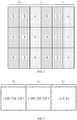
FIG. 1 is a schematic diagram of a pixel structure of a display panel according to an embodiment of the present invention. -
FIG. 2 is a schematic flow chart of a method of driving a display panel according to an embodiment of the present invention. -
FIG. 3 is a schematic diagram showing an arrangement of sub-pixels of the display panel shown inFIG. 1 . -
FIG. 4 is a schematic diagram showing color components of three adjacent logical pixels when the display panel shown inFIG. 1 displays an edge region of a first image. -
FIG. 5 is a schematic diagram showing color components of three adjacent logical pixels when the display panel shown inFIG. 1 displays an edge region of a second image. -
FIG. 6 is a schematic diagram showing color components of the respective sub-pixels when an edge region of a first image is displayed by the method of driving a display panel shown inFIG. 2 . -
FIG. 7 is a schematic diagram showing color components of the respective sub-pixels when an edge region of a second image is displayed by the method of driving a display panel. -
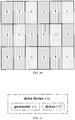
FIG. 8 is a schematic diagram showing color components of respective sub-pixels when an edge region of a second image is displayed by an existing sub-pixel rendering technique. -
FIG. 9 is a schematic diagram showing color components of respective sub-pixels when an edge region of a first image is displayed by an existing sub-pixel rendering technique. -
FIG. 10 is a schematic diagram of a pixel structure of a display panel according to another embodiment of the present invention. -
FIG. 11 is a schematic diagram showing a structure of a driving device for a display panel according to an embodiment of the present invention. - The technical solutions of the various exemplary embodiments provided by the present invention are clearly and completely described in the following with reference to the accompanying drawings. The following embodiments and their technical features can be combined with each other without conflict.
- Please refer to
FIG. 1 , which is a schematic diagram of a pixel structure of a display panel according to an embodiment of the present invention. The display panel includes a plurality of data lines Dx arranged in a column direction, a plurality of scanning lines Gy arranged in a row direction, and a plurality of pixel units Pz defined by the plurality of scanning lines Gy and the plurality of data lines Dx. These pixel units Pz may be arranged in a matrix and may be identical in structure and size. As shown inFIG. 3 , in the row direction, each of the pixel units Pz may include three sub-pixels, which are a blue sub-pixel B, a red sub-pixel R, and a green sub-pixel G, respectively. Accordingly, the sub-pixels of the three colors are alternately arranged in the row direction, that is, a luminous color of any sub-pixel is different from luminous colors of the two adjacent sub-pixels in the row direction. - The driving method shown in
FIG. 2 can drive the display panel. Referring toFIG. 2 , a driving method according to an embodiment of the present invention may include steps S21 to S25. - S21: constituting a logical pixel by adjacent ones of the sub-pixels in the row direction, and dividing the pixel units in the row direction into a plurality of logical pixel groups, each of the logical pixel groups comprising a first logical pixel, a second logical pixel, and a third logical pixel arranged sequentially in the row direction, the second logical pixel lacking a predetermined color possessed by its adjacent sub-pixels.
- In this embodiment, adjacent ones of the sub-pixels in the row direction may be selected to constitute a logical pixel. Taking the adjacent two pixel units Pz shown in
FIG. 3 as an example, the blue sub-pixel B and the red sub-pixel R constitute a first logical pixel L1, the green sub-pixel G and the blue sub-pixel B constitute a second logical pixel L2, and the red sub-pixel R and the green sub-pixel G constitute a third logical pixel L3. - Each of the logical pixels includes only the sub-pixels of two color, and lacks sub-pixels of the colors included in its adjacent logical pixels. For example, the second logical pixel L2 lacks the red sub-pixel R included in the first logical pixel L1 and the third logical pixel L3.
- S22: obtaining color components of the predetermined colors in the first logical pixel, the second logical pixel, and the third logical pixel for image display.
- For example, as shown in
FIG. 4 , when the display panel displays the edge region of the first image, the color components of red, green, and blue colors in the first logical pixel L1 are (225, 225, 225); the color components of red, green, and blue colors in the second logical pixel L2 are (225, 225, 225); and the color components of red, green, and blue colors in the third logical pixel L3 are (0, 0, 0). - For another example, as shown in
FIG. 5 , when the display panel displays the edge region of the second image, the color components of red, green, and blue colors in the first logical pixel L1 are (0, 0, 0); the color components of red, green, and blue colors in the second logical pixel L2 are (225, 225, 225); and the color components of red, green, and blue colors in the third logical pixel L3 are (225, 225, 225). - S23: calculating a first color component difference between the predetermined colors in the second logical pixel and the first logical pixel, and a second color component difference between the predetermined colors in the second logical pixel and the third logical pixel, and comparing absolute values of a first color component difference and a second color component difference.
- Taking the red color as the predetermined color as an example,
when the display panel displays the edge region of the first image as shown inFIG. 4 , the red color component P2C2 in the second logical pixel L2 is 225, and the red color component P1C2 in the first logical pixel L1 is 225, and the red color component P3C2 in the third logical pixel L3 is 0, a first color component difference P2C2 - P1C2 is 0, a second color component difference P3C2 - P2C2 is -225, and an absolute value of the first color component difference | P2C2 - P1C2 | is 0, an absolute value of the second color component difference | P3C2 - P2C2 | is 225. - When the display panel displays the edge region of the second image as shown in
FIG. 5 , the red color component P2C2 in the second logical pixel L2 is 225, the red color component P1C2 in the first logical pixel L1 is 0, and the red color component P3C2 in the third logical pixel L3, a first color component difference P2C2 - P1C2 is 225, a second color component difference P3C2 - P2C2 is 0, and an absolute value of a first color component difference | P2C2 - P1C2 | is 225 The absolute value of the second color component difference is | P3C2 - P2C2 | is 0. - S24: determining luminous intensity of the sub-pixel of the predetermined color when the second logical pixel displays an image according to the color component of the predetermined color in the first logical pixel, if the absolute value of the first color component difference is less than or equal to the absolute value of the second color component difference.
- When the display panel displays the edge region of the first image, since the absolute value of a first color component difference is smaller than the absolute value of a second color component difference, it will comply with
| P2C2 - P1C2 | < | P3C2 - P2C2 | - In this embodiment, the luminous intensity of the red sub-pixel R when the second logical pixel L2 displays an image is determined according to the color component of the red color in the first logical pixel L1, that is, the luminous intensity of the red sub-pixel R when the second logical pixel L2 displays the edge region of the first image.
- In this embodiment, the luminous intensity of the red sub-pixel R can be determined by the following formula:

- When N is 1/2, the luminous intensity L of the red sub-pixel R obtained in this embodiment is 225, as shown in
FIG. 6 , but the red sub-pixel R of such a luminous intensity is located at a side of the second logical pixel L2 away from the third logical pixel L3. while at a side of the second logical pixel L2 adjacent to the third logical pixel L3, the luminous intensity of the red sub-pixel R is still 0, so that the contrast of the edge region of the first image can be accurately displayed, preventing the distortion in the edge region of the first image. - S25: determining luminous intensity of the sub-pixel of the predetermined color when the second logical pixel displays the image according to the color component of the predetermined color in the third logical pixel, if the absolute value of the first color component difference is greater than the absolute value of the second color component difference.
- When the display panel displays the edge region of the second image, since the absolute value of a first color component difference is greater than the absolute value of a second color component difference, it will comply with
| P2C2 - P1C2 | > | P3C2 - P2C2 | - In this embodiment, the luminous intensity of the red sub-pixel R when the second logical pixel L2 is displayed is determined according to the color component of red sub-pixel R in the third logical pixel L3.
- In this embodiment, the luminous intensity L of the red sub-pixel R is 225 according to the above formula I, as shown in
FIG. 7 , but the red sub-pixel R of such a luminous intensity is located at a side of the second logical pixel L2 away from the first logical pixel L1, while at a side of the second logical pixel L2 adjacent to the first logical pixel L1, the luminous intensity of the red sub-pixel R is still 0, so that the contrast of the edge region of the second image can be accurately displayed, preventing the distortion in the edge region of the second image. - In a case of using the existing sub-pixel rendering technology to drive the display panel, if the red sub-pixel R of the first logical pixel L1 is fixedly selected as the shared sub-pixel of the second logical pixel L2, when the edge region of the first image is displayed, at the side of the second logical pixel L2 adjacent to the third logical pixel L3, the red sub-pixel R has an luminous intensity of 0, and as shown in
FIG. 6 , the contrast of the edge region of the first image can be accurately displayed to avoid distortion. However, when the edge region of the second image is displayed, the luminous intensity of the red sub-pixel R is 127 at the side of the second logical pixel L2 adjacent to the first logical pixel L1, as shown inFIG. 8 , resulting in color aliasing in the edge region of the second image, such that contrast distortion occurs. - If the red sub-pixel R of the third logical pixel L3 is fixedly selected as the shared sub-pixel of the second logical pixel L2, when the edge region of the first image is displayed, at the side of the second logical pixel L2 adjacent to the third logical pixel L3, the red sub-pixel R has a luminous intensity of 127. As shown in
FIG. 9 , color aliasing occurs in the edge region of the second image, and contrast distortion occurs. When the edge region of the second image is displayed, on the side of the second logical pixel L2 adjacent to the first logical pixel L1, the luminous intensity of the red sub-pixel R is 0, as shown inFIG. 7 , such that the edge region of the first image can be accurately displayed, and contrast distortion is avoided. - Therefore, the present invention determines sub-pixels shared by sub-pixel rendering technology through comparing differences of the color components, and the sub-pixels shared by the display image are not fixed. Since the sub-pixels with the smallest absolute value of the color component difference are selected for sharing, a contrast of an edge region of an image is improved, and distortion of an edge region of an image is reduced.
- The present invention is applicable not only to the display panel having a pixel structure of an RGB stripe type shown in
FIG. 1 , but also to the display panel having a pixel structure of an RGB delta type shown inFIG. 10 . Referring toFIG. 10 , the sub-pixels of the three colors (the blue sub-pixel B, the red sub-pixel R, and the green sub-pixel G) are also alternately arranged in the row direction. For the pixel structure of this embodiment, the present invention can still select adjacent ones of the sub-pixels in the column direction to constitute the first logical pixel L1, the second logical pixel L2, and the third logical pixel L3, respectively. - The present invention also provides a driving device for a display panel. As shown in
FIG. 11 , thedrive device 110 includes aprocessor 111 and adriver 112 coupled to theprocessor 111. - The
processor 111 is configured to constitute a logical pixel by adjacent ones of the sub-pixels in the row direction, and dividing the pixel units in the row direction into a plurality of logical pixel groups, each of the logical pixel groups comprising a first logical pixel, a second logical pixel, and a third logical pixel arranged sequentially in the row direction, the second logical pixel lacking a predetermined color possessed by its adjacent sub-pixels. - The
processor 111 is further configured to acquire the color components of the predetermined colors in the first logical pixel, the second logical pixel, and the third logical pixel when the image is displayed. - The
processor 111 is further configured to calculate a first color component difference between the predetermined colors in the second logical pixel and the first logical pixel, and a second color component difference between the predetermined colors in the second logical pixel and the third logical pixel, and compare absolute values of the first color component difference and the second color component difference. - If the absolute value of the first color component difference is less than or equal to the absolute value of the second color component difference, the
processor 111 determines luminous intensity of the sub-pixel of each the predetermined color when the second logical pixel displays an image according to the color component of the predetermined color in the first logical pixel. - If the absolute value of the first color component difference is greater than the absolute value of the second color component difference, the
processor 111 determines luminous intensity of the sub-pixel of each the predetermined color when the second logical pixel displays the image according to the color component of the predetermined color in the third logical pixel is determined. - The
driver 112 is configured to drive the sub-pixel of the predetermined color to emit light of the luminous intensity determined by theprocessor 111 when the second logical pixel displays - The structural elements of the
driving device 110 of this embodiment correspond to the driving method of the above embodiments, and have the same technical effects. - While the invention has been described by way of example and in terms of the preferred embodiments, it is to be understood that the invention is not limited to the disclosed embodiments. To the contrary, it is intended to cover various modifications and similar arrangements. Therefore, the scope of the appended claims should be accorded the broadest interpretation so as to encompass all such modifications and similar arrangements.
Claims (12)
- A method of driving a display panel, wherein the display panel comprises a plurality of identical pixel units arranged in a matrix, each of the pixel units comprises sub-pixels of three colors of red, green and blue in a row direction, and the method of driving a display panel comprises:constituting a logical pixel by adjacent ones of the sub-pixels in the row direction, and dividing the pixel units in the row direction into a plurality of logical pixel groups, each of the logical pixel groups comprising a first logical pixel, a second logical pixel, and a third logical pixel arranged sequentially in the row direction, the second logical pixel lacking a predetermined color possessed by its adjacent sub-pixels;obtaining color components of the predetermined colors in the first logical pixel, the second logical pixel, and the third logical pixel for image display;calculating a first color component difference between the predetermined colors in the second logical pixel and the first logical pixel, and a second color component difference between the predetermined colors in the second logical pixel and the third logical pixel, and comparing absolute values of the first color component difference and the second color component difference;determining luminous intensity of the sub-pixel of the predetermined color when the second logical pixel displays an image according to the color component of the predetermined color in the first logical pixel, if the absolute value of the first color component difference is less than or equal to the absolute value of the second color component difference; anddetermining luminous intensity of the sub-pixel of the predetermined color when the second logical pixel displays the image according to the color component of the predetermined color in the third logical pixel, if the absolute value of the first color component difference is greater than the absolute value of the second color component difference,wherein the luminous intensity of the sub-pixel of the predetermined color is determined according to a formula as follows:

- The method of driving a display panel according to claim 1, wherein N = 1/2.
- A method of driving a display panel, wherein the display panel comprises a plurality of identical pixel units arranged in a matrix, each of the pixel units comprises a plurality of sub-pixels of different colors in a predetermined direction, and the method of driving a display panel comprises:constituting a logical pixel by adjacent ones of the sub-pixels in the row direction, and dividing the pixel units in the row direction into a plurality of logical pixel groups, each of the logical pixel groups comprising a first logical pixel, a second logical pixel, and a third logical pixel arranged sequentially in the row direction, the second logical pixel lacking a predetermined color possessed by its adjacent sub-pixels;obtaining color components of the predetermined colors in the first logical pixel, the second logical pixel, and the third logical pixel for image display;calculating a first color component difference between the predetermined colors in the second logical pixel and the first logical pixel, and a second color component difference between the predetermined colors in the second logical pixel and the third logical pixel, and comparing absolute values of the first color component difference and the second color component difference;determining luminous intensity of the sub-pixel of the predetermined color when the second logical pixel displays an image according to the color component of the predetermined color in the first logical pixel, if the absolute value of the first color component difference is less than or equal to the absolute value of the second color component difference; anddetermining luminous intensity of the sub-pixel of the predetermined color when the second logical pixel displays the image according to the color component of the predetermined color in the third logical pixel, if the absolute value of the first color component difference is greater than the absolute value of the second color component difference.
- The method of driving a display panel according to claim 3, wherein the predetermined direction comprises a row direction.
- The method of driving a display panel according to claim 3, wherein each of the pixel units comprises the sub-pixels of three different colors, which are red, green, and blue, respectively.

- The method of driving a display panel according to claim 3, wherein the luminous intensity of the sub-pixel of the predetermined color is determined according to a formula as follows:

- The method of driving a display panel according to claim 6, wherein N = 1/2.
- A driving device for a display panel, wherein the display panel comprises a plurality of identical pixel units arranged in a matrix, each of the pixel units comprises a plurality of sub-pixels of different colors in a predetermined direction, and the method of driving a display panel comprises:a processor configured to constitute a logical pixel by adjacent ones of the sub-pixels in the row direction, and dividing the pixel units in the row direction into a plurality of logical pixel groups, each of the logical pixel groups comprising a first logical pixel, a second logical pixel, and a third logical pixel arranged sequentially in the row direction, the second logical pixel lacking a predetermined color possessed by its adjacent sub-pixels;the processor further configured to acquire color components of the predetermined colors in the first logical pixel, the second logical pixel, and the third logical pixel for image display;the processor further configured to calculate a first color component difference between the predetermined colors in the second logical pixel and the first logical pixel, and a second color component difference between the predetermined colors in the second logical pixel and the third logical pixel, and compare absolute values of the first color component difference and the second color component difference;wherein if the absolute value of the first color component difference is less than or equal to the absolute value of the second color component difference, the processor determines luminous intensity of the sub-pixel of each the predetermined color when the second logical pixel displays an image according to the color component of the predetermined color in the first logical pixel; andif the absolute value of the first color component difference is greater than the absolute value of the second color component difference, the processor determines luminous intensity of the sub-pixel of each the predetermined color when the second logical pixel displays the image according to the color component of the predetermined color in the third logical pixel is determined; anda driver configured to drive the sub-pixel of the predetermined color to emit light of the luminous intensity determined by the processor when the second logical pixel displays.
- The driving device according to claim 8, wherein the predetermined direction comprises a row direction.
- The driving apparatus according to claim 8, wherein each of the pixel units comprises sub-pixels of three different colors, which are red, green, and blue, respectively.
- The driving apparatus according to claim 8, wherein the luminous intensity of the sub-pixel of the predetermined color is determined according to a formula as follows:

- The driving device according to claim 11, wherein N = 1/2.
Applications Claiming Priority (2)
| Application Number | Priority Date | Filing Date | Title |
|---|---|---|---|
| CN201710295392.2A CN106898291B (en) | 2017-04-28 | 2017-04-28 | The driving method and driving device of display panel |
| PCT/CN2017/086229 WO2018196086A1 (en) | 2017-04-28 | 2017-05-27 | Drive method and drive device for display panel |
Publications (2)
| Publication Number | Publication Date |
|---|---|
| EP3618043A1 true EP3618043A1 (en) | 2020-03-04 |
| EP3618043A4 EP3618043A4 (en) | 2020-12-30 |
Family
ID=59196704
Family Applications (1)
| Application Number | Title | Priority Date | Filing Date |
|---|---|---|---|
| EP17907405.9A Withdrawn EP3618043A4 (en) | 2017-04-28 | 2017-05-27 | Drive method and drive device for display panel |
Country Status (6)
| Country | Link |
|---|---|
| US (1) | US10847079B2 (en) |
| EP (1) | EP3618043A4 (en) |
| JP (1) | JP2020518022A (en) |
| KR (1) | KR102265774B1 (en) |
| CN (1) | CN106898291B (en) |
| WO (1) | WO2018196086A1 (en) |
Families Citing this family (4)
| Publication number | Priority date | Publication date | Assignee | Title |
|---|---|---|---|---|
| CN108428435B (en) * | 2018-03-29 | 2019-11-29 | 合肥工业大学 | The verifying display methods of one sub-pixel rendering |
| EP4485061A3 (en) * | 2018-07-03 | 2025-04-16 | Wuxi CLEARink Limited | Color filter arrays for tir-based image displays |
| CN112673474B (en) * | 2019-07-31 | 2022-08-19 | 京东方科技集团股份有限公司 | Electroluminescent display panel and display device |
| CN112585761B (en) | 2019-07-31 | 2022-04-19 | 京东方科技集团股份有限公司 | Display substrate and display device |
Family Cites Families (26)
| Publication number | Priority date | Publication date | Assignee | Title |
|---|---|---|---|---|
| EP0603833B1 (en) * | 1992-12-22 | 1999-06-30 | Konica Corporation | Color image processing apparatus for smoothing compensation of an image |
| KR100493165B1 (en) * | 2002-12-17 | 2005-06-02 | 삼성전자주식회사 | Method and apparatus for rendering image signal |
| US7609882B2 (en) * | 2005-05-25 | 2009-10-27 | Himax Technologies Limited | Image compression and decompression method capable of encoding and decoding pixel data based on a color conversion method |
| KR101212158B1 (en) * | 2006-02-27 | 2012-12-13 | 엘지디스플레이 주식회사 | Liquid crystal display device and method for driving the same |
| US8018476B2 (en) * | 2006-08-28 | 2011-09-13 | Samsung Electronics Co., Ltd. | Subpixel layouts for high brightness displays and systems |
| JP5256283B2 (en) * | 2007-05-18 | 2013-08-07 | 三星ディスプレイ株式會社 | Image color balance adjustment for display panels with 2D sub-pixel layout |
| JP5293923B2 (en) * | 2008-01-09 | 2013-09-18 | 株式会社リコー | Image processing method and apparatus, image display apparatus and program |
| WO2009093947A1 (en) * | 2008-01-21 | 2009-07-30 | Telefonaktiebolaget Lm Ericsson (Publ) | Pixel block processing |
| WO2009092455A2 (en) * | 2008-01-21 | 2009-07-30 | Telefonaktiebolaget Lm Ericsson (Publ) | Prediction-based image processing |
| JP2011118000A (en) * | 2009-11-30 | 2011-06-16 | Fujitsu Ten Ltd | Image processing apparatus and image processing method |
| KR101332495B1 (en) * | 2010-05-20 | 2013-11-26 | 엘지디스플레이 주식회사 | Image Porcessing Method And Display Device Using The Same |
| US20110285713A1 (en) * | 2010-05-21 | 2011-11-24 | Jerzy Wieslaw Swic | Processing Color Sub-Pixels |
| KR101934094B1 (en) * | 2011-08-01 | 2019-03-26 | 삼성디스플레이 주식회사 | Display device and driving method of the same |
| KR101901358B1 (en) * | 2011-12-23 | 2018-11-06 | 엘지디스플레이 주식회사 | Liquid crystal display and stereoscopic image display using the same |
| KR102025876B1 (en) * | 2012-03-16 | 2019-09-27 | 삼성디스플레이 주식회사 | Data rendering method, data rendering device, and display comprising the data rendering device |
| KR102016424B1 (en) * | 2013-04-12 | 2019-09-02 | 삼성디스플레이 주식회사 | Data processing device and display system having the same |
| KR102231279B1 (en) * | 2013-10-30 | 2021-03-25 | 삼성디스플레이 주식회사 | Apparatus and method for encoding a image data |
| CN103700329B (en) * | 2013-12-13 | 2015-11-11 | 北京京东方光电科技有限公司 | The display packing of display panel |
| JP2015118113A (en) * | 2013-12-16 | 2015-06-25 | 株式会社ジャパンディスプレイ | Display device |
| CN103886808B (en) * | 2014-02-21 | 2016-02-24 | 北京京东方光电科技有限公司 | Display packing and display device |
| CN106033657B (en) * | 2015-03-13 | 2019-09-24 | 联咏科技股份有限公司 | Display device and display driving method |
| CN106157876B (en) * | 2015-03-27 | 2019-04-23 | 上海和辉光电有限公司 | The display methods and display of display image |
| CN104821147B (en) * | 2015-05-27 | 2017-06-27 | 京东方科技集团股份有限公司 | One sub-pixel rendering intent |
| CN105609033A (en) * | 2015-12-18 | 2016-05-25 | 武汉华星光电技术有限公司 | Pixel rendering method, pixel rendering device and display device |
| CN105931605B (en) * | 2016-05-12 | 2018-09-18 | 深圳市华星光电技术有限公司 | A kind of method for displaying image and display device |
| CN106409266B (en) * | 2016-12-14 | 2019-09-17 | Tcl集团股份有限公司 | One sub-pixel rendering method and rendering device |
-
2017
- 2017-04-28 CN CN201710295392.2A patent/CN106898291B/en active Active
- 2017-05-27 KR KR1020197035229A patent/KR102265774B1/en active Active
- 2017-05-27 JP JP2019558449A patent/JP2020518022A/en active Pending
- 2017-05-27 EP EP17907405.9A patent/EP3618043A4/en not_active Withdrawn
- 2017-05-27 WO PCT/CN2017/086229 patent/WO2018196086A1/en not_active Ceased
- 2017-05-27 US US16/607,108 patent/US10847079B2/en active Active
Also Published As
| Publication number | Publication date |
|---|---|
| CN106898291A (en) | 2017-06-27 |
| EP3618043A4 (en) | 2020-12-30 |
| CN106898291B (en) | 2019-08-02 |
| US10847079B2 (en) | 2020-11-24 |
| KR102265774B1 (en) | 2021-06-15 |
| WO2018196086A1 (en) | 2018-11-01 |
| KR20190141756A (en) | 2019-12-24 |
| US20200135085A1 (en) | 2020-04-30 |
| JP2020518022A (en) | 2020-06-18 |
Similar Documents
| Publication | Publication Date | Title |
|---|---|---|
| EP3895153B1 (en) | Method of driving pixel arrangement structure having plurality of subpixels, driving chip for driving pixel arrangement structure having plurality of subpixels, display apparatus, and computer-program product | |
| US11037523B2 (en) | Display method of display panel that uses different display algorithms for different display areas, display panel and display device | |
| US20140362127A1 (en) | Display device, pixel array, and color compensating method | |
| US9262957B2 (en) | Pixel arrangement of color display panel | |
| EP4044165B1 (en) | Organic light emitting display device | |
| CN103886809B (en) | Display packing and display device | |
| US9886878B2 (en) | Pixel array, display driving method, display driving device and display device | |
| CN107492359B (en) | Display device and driving method thereof | |
| US20170154587A1 (en) | Liquid crystal display panel and driving method thereof | |
| CN107331341B (en) | Sub-pixel rendering method and system | |
| CN104166263B (en) | Pixel array and display device | |
| WO2011102343A1 (en) | Display device | |
| US9613564B2 (en) | Image displaying method and image display apparatus | |
| US11710439B2 (en) | Subpixel rendering for display panels including multiple display regions with different pixel layouts | |
| US9508296B2 (en) | Driving method of pixel array, driving module of pixel array and display device | |
| US10297182B2 (en) | Pixel array having sub-pixel groups and driving method thereof and display panel | |
| US20160035263A1 (en) | Display method of display panel | |
| US10847079B2 (en) | Method of driving display panel and driving device | |
| CN104795015A (en) | Image display driving method, image display driving device and image display driving equipment | |
| WO2017092218A1 (en) | Sub-pixel rendering method and rendering apparatus | |
| US20160203800A1 (en) | Display method of display panel, display panel and display device | |
| US8184126B2 (en) | Method and apparatus processing pixel signals for driving a display and a display using the same | |
| CN105096887B (en) | A kind of dot structure, display panel, display device and driving method | |
| CN104464684A (en) | The method of rendering the screen of the display | |
| US20220246078A1 (en) | Image processing apparatus |
Legal Events
| Date | Code | Title | Description |
|---|---|---|---|
| STAA | Information on the status of an ep patent application or granted ep patent |
Free format text: STATUS: THE INTERNATIONAL PUBLICATION HAS BEEN MADE |
|
| PUAI | Public reference made under article 153(3) epc to a published international application that has entered the european phase |
Free format text: ORIGINAL CODE: 0009012 |
|
| STAA | Information on the status of an ep patent application or granted ep patent |
Free format text: STATUS: REQUEST FOR EXAMINATION WAS MADE |
|
| 17P | Request for examination filed |
Effective date: 20191125 |
|
| AK | Designated contracting states |
Kind code of ref document: A1 Designated state(s): AL AT BE BG CH CY CZ DE DK EE ES FI FR GB GR HR HU IE IS IT LI LT LU LV MC MK MT NL NO PL PT RO RS SE SI SK SM TR |
|
| AX | Request for extension of the european patent |
Extension state: BA ME |
|
| DAV | Request for validation of the european patent (deleted) | ||
| DAX | Request for extension of the european patent (deleted) | ||
| A4 | Supplementary search report drawn up and despatched |
Effective date: 20201126 |
|
| RIC1 | Information provided on ipc code assigned before grant |
Ipc: G09G 3/20 20060101ALI20201120BHEP Ipc: G09G 5/391 20060101ALI20201120BHEP Ipc: G09G 5/02 20060101AFI20201120BHEP |
|
| STAA | Information on the status of an ep patent application or granted ep patent |
Free format text: STATUS: THE APPLICATION IS DEEMED TO BE WITHDRAWN |
|
| 18D | Application deemed to be withdrawn |
Effective date: 20210626 |