EP3617849A1 - A real time virtual reality (vr) system and related methods - Google Patents
A real time virtual reality (vr) system and related methods Download PDFInfo
- Publication number
- EP3617849A1 EP3617849A1 EP18382625.4A EP18382625A EP3617849A1 EP 3617849 A1 EP3617849 A1 EP 3617849A1 EP 18382625 A EP18382625 A EP 18382625A EP 3617849 A1 EP3617849 A1 EP 3617849A1
- Authority
- EP
- European Patent Office
- Prior art keywords
- operator
- sensing elements
- visualization
- aircraft
- real time
- Prior art date
- Legal status (The legal status is an assumption and is not a legal conclusion. Google has not performed a legal analysis and makes no representation as to the accuracy of the status listed.)
- Withdrawn
Links
Images

Classifications
-
- G—PHYSICS
- G06—COMPUTING; CALCULATING OR COUNTING
- G06F—ELECTRIC DIGITAL DATA PROCESSING
- G06F3/00—Input arrangements for transferring data to be processed into a form capable of being handled by the computer; Output arrangements for transferring data from processing unit to output unit, e.g. interface arrangements
- G06F3/01—Input arrangements or combined input and output arrangements for interaction between user and computer
- G06F3/011—Arrangements for interaction with the human body, e.g. for user immersion in virtual reality
- G06F3/014—Hand-worn input/output arrangements, e.g. data gloves
-
- B—PERFORMING OPERATIONS; TRANSPORTING
- B64—AIRCRAFT; AVIATION; COSMONAUTICS
- B64F—GROUND OR AIRCRAFT-CARRIER-DECK INSTALLATIONS SPECIALLY ADAPTED FOR USE IN CONNECTION WITH AIRCRAFT; DESIGNING, MANUFACTURING, ASSEMBLING, CLEANING, MAINTAINING OR REPAIRING AIRCRAFT, NOT OTHERWISE PROVIDED FOR; HANDLING, TRANSPORTING, TESTING OR INSPECTING AIRCRAFT COMPONENTS, NOT OTHERWISE PROVIDED FOR
- B64F5/00—Designing, manufacturing, assembling, cleaning, maintaining or repairing aircraft, not otherwise provided for; Handling, transporting, testing or inspecting aircraft components, not otherwise provided for
- B64F5/10—Manufacturing or assembling aircraft, e.g. jigs therefor
-
- B—PERFORMING OPERATIONS; TRANSPORTING
- B64—AIRCRAFT; AVIATION; COSMONAUTICS
- B64F—GROUND OR AIRCRAFT-CARRIER-DECK INSTALLATIONS SPECIALLY ADAPTED FOR USE IN CONNECTION WITH AIRCRAFT; DESIGNING, MANUFACTURING, ASSEMBLING, CLEANING, MAINTAINING OR REPAIRING AIRCRAFT, NOT OTHERWISE PROVIDED FOR; HANDLING, TRANSPORTING, TESTING OR INSPECTING AIRCRAFT COMPONENTS, NOT OTHERWISE PROVIDED FOR
- B64F5/00—Designing, manufacturing, assembling, cleaning, maintaining or repairing aircraft, not otherwise provided for; Handling, transporting, testing or inspecting aircraft components, not otherwise provided for
- B64F5/40—Maintaining or repairing aircraft
-
- G—PHYSICS
- G06—COMPUTING; CALCULATING OR COUNTING
- G06F—ELECTRIC DIGITAL DATA PROCESSING
- G06F3/00—Input arrangements for transferring data to be processed into a form capable of being handled by the computer; Output arrangements for transferring data from processing unit to output unit, e.g. interface arrangements
- G06F3/01—Input arrangements or combined input and output arrangements for interaction between user and computer
- G06F3/011—Arrangements for interaction with the human body, e.g. for user immersion in virtual reality
- G06F3/013—Eye tracking input arrangements
-
- G—PHYSICS
- G06—COMPUTING; CALCULATING OR COUNTING
- G06F—ELECTRIC DIGITAL DATA PROCESSING
- G06F3/00—Input arrangements for transferring data to be processed into a form capable of being handled by the computer; Output arrangements for transferring data from processing unit to output unit, e.g. interface arrangements
- G06F3/01—Input arrangements or combined input and output arrangements for interaction between user and computer
- G06F3/048—Interaction techniques based on graphical user interfaces [GUI]
- G06F3/0481—Interaction techniques based on graphical user interfaces [GUI] based on specific properties of the displayed interaction object or a metaphor-based environment, e.g. interaction with desktop elements like windows or icons, or assisted by a cursor's changing behaviour or appearance
- G06F3/04815—Interaction with a metaphor-based environment or interaction object displayed as three-dimensional, e.g. changing the user viewpoint with respect to the environment or object
-
- G—PHYSICS
- G06—COMPUTING; CALCULATING OR COUNTING
- G06F—ELECTRIC DIGITAL DATA PROCESSING
- G06F3/00—Input arrangements for transferring data to be processed into a form capable of being handled by the computer; Output arrangements for transferring data from processing unit to output unit, e.g. interface arrangements
- G06F3/14—Digital output to display device ; Cooperation and interconnection of the display device with other functional units
Definitions
- the present invention refers to a real time VR system for providing a VR visualization of a working area of an aircraft and methods to obtain said VR visualization.
- the proposed system is a virtual reality VR system that solves the aforementioned drawbacks and provides other advantages that are described below.
- the proposed virtual reality system can capture the position and attitude of the hands of the operator and any other means as e.g. tools, machines, fixtures, etc. in relation with fixed points or reference points located in known positions of a working area of the aircraft having a difficult access and wherein the operator must complete the installation.
- a VR visualization obtained by the proposed VR system can be displayed to the operator.
- the VR visualization can represent the operator's hands and tools within the target area having difficult access without the need for a direct sight view of the location that would require larger holes or accessory holes in the structure of the aircraft.
- a virtual reality, VR system for providing a real time VR visualization of a target area of an aircraft which may have a difficult access.
- the target area can be an operator's working area for assembly or element installation within the aircraft.
- the system comprises one or more reference targets established in known locations in the target area of an aircraft.
- the one or more reference targets comprise target points located by means of holes.
- the holes can be made by numeric control (NC).
- the system comprises hand gloves configured to fit the operator's hands.
- a plurality of sensing elements established on at least on the operator's hand gloves, wherein the sensing elements provide information about the operator's hands location.
- the plurality of sensing elements are also established in operator's tools hand tools or power tools and fixtures instrumented, e.g. electrical tools, pneumatic tools and liquid-fuel tools) and hydraulic tools.
- a reception device adapted to receive the information provided by the sensing elements to provide relative locations of the sensing elements against the one or more reference targets established in said known locations and produces the VR information for direct visualization.
- the visualization device are VR glasses. Combination of the reception and visualization devices can happen.
- the information about the operator's hands comprise information of the location and attitude of each finger and an overall location and orientation of each operator's hand.
- the reception device comprises processing means adapted to build the real time VR visualization that represents at least the operator's hands against the area of the aircraft based on the relative locations of the sensing elements and display means adapted to display the real time VR visualization to the operator.
- the processing means are further adapted to visualize operator's tools and fixtures instrumented in the VR visualization.
- the display means comprises a stereo display monitor.
- the method comprises establishing one or more reference targets in known locations of a target area of an aircraft with difficult access.
- the area can be a working area for assembly, installation, maintenance, etc.
- the method comprises establishing a plurality of sensing elements on at least on operator's hand gloves.
- the sensing elements can be installed in tools, operator's fixtures, machines, etc.
- the sensing element provide information about the operator's hands location or any other element location.
- the method comprises receiving at a reception device the information provided by the sensing elements to provide relative locations (as e.g. spatial coordinates) of the sensing elements against the one or more reference targets established in the known locations of the working area.
- the method also comprises the step of building the VR visualization that represents at least the operator's hands against the known locations of the aircraft based on the relative locations of the sensing elements and the step of displaying the VR visualization to the operator.
- the invention also proposes a method to provide the operator about the exact position and orientation of the element to be installed, the operator's hands and any other installation means like tools or fixtures in the area with difficult access within the aircraft.
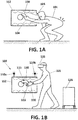
- Figure 1A shows a first example of a conventional installation procedure performed by an operator (101) in a target area (112) of an aircraft which has a difficult access for the operator.
- Figure 1A shows an operator (101) holding a tool or installation tool (130) with his bare hand (104) trying to access a working target area (112) of the aircraft having a difficult access through an access hole (105).
- the operator (101) in order to obtain direct sight to the working area in order to perform the installation task, the operator (101) must bend and achieve and uncomfortable and unstable body position that may cause long term injuries and affect the final overall result of the installation.
- Figure 1B shows an example of a VR system (100) for providing a VR visualization of the target area of an aircraft (112) used in the first example of conventional installation procedure of figure 1A .
- the target area of the aircraft (112) can be a working area having a difficult access and wherein an installation must be performed by an operator as e.g. an assembly fitter operator.
- the system (100) comprises two reference targets (110a) and (110b) which can be established in known locations of this target area of the aircraft (112).
- the example VR system (100) comprises two reference targets (110a) and (110b) located on an upper part of the working area as it is shown in figure 1B .
- the system (100) also comprises hand gloves (120) configured to fit the operator's hands.
- the system (100) comprises a plurality of sensing elements (115) established on the operator's hand glove (120) and on an operator's installation tool (130).
- the sensing elements (115) provide information about the operator's hands and operator's installation tool (130) location.
- the system (100) can capture the position and attitude of the hand of the operator within the glove (120) and the operator's tool (130) in relation with fixed reference targets (110a) and (110b) in the area of the aircraft.
- the VR system (100) comprises a reception device (126) as e.g. a portable processor that receives the information provided by the sensing elements (115) to provide relative locations of the sensing elements against the fixed reference targets (110a) and (110b) established in the aforementioned locations.
- the reception device (126) comprises a processor that builds the VR visualization that visualizes the operator's hands and operator's installation tool (130) against the area of the aircraft based on the relative locations of the sensing elements (115).
- the VR system (100) comprises output means as display means that represents the VR visualization to the operator (101).
- the VR visualization can be displayed by display means (125) as e.g. VR glasses.
- the display means (125) comprises a stereo display monitor.
- the display means (125) also comprises audio means for aural representation and haptic means for contact or force representation.
- the operator does not need to bend as shown in figure 1A , and hence, injuries are minimized and poor operator's postures avoided.
- Figure 2A shows a second example of a conventional situation wherein the operator (101) has to perform an installation operation in another target area (212) of an aircraft.
- the operator (101) access the target area (212) through an accessing hole (207).
- the operator (101) holds another installation tool (203) with his bare hand (104).
- a direct sigh view hole (205) that permits the operator to have direct sight must be performed in the structure of the area (212).
- this direct sight criteria affects the areas where certain elements can be installed but in all the cases, the sizes of holes causes an increase of weight for the structure, i.e. reinforcements around the holes or simply due to the change in load path. It can be seen by direct paths (202) the direct sight required by the operator (101) in order to be able to use the installation tool (203) for performing a particular installation.
- Figure 2B shows one of the main advantages achieved by an example of a VR system (100) according to the present disclosure used in the second example of installation procedure of figure 2A , i.e. no direct sight criteria is needed.
- Figure 2B shows the VR system (100) comprising the two reference targets (110a) and (110b) established in known locations in the target area of an aircraft (112) and hand gloves (120) configured to fit the operator's hands holding a tool (230).
- the sensing elements (115) are established on the hand glove (120) of the operator 101.
- the sensing elements (115) provide information about the operator's hands location.
- the reception device (126) receives the information provided by the sensing elements (115) to provide relative locations of these sensing elements (215) against the two reference targets (110a) and (110b) established in two known locations on surface of the target area (112) of the aircraft.
- the VR system (100) can capture the position and attitude of the hand of the operator (101) within the glove (120) and a tool (230) in relation with the fixed reference targets (110a) and (110b) in the target area (212) of the aircraft.
- the operator (101) access the target area (212) through an accessing hole (207).
- the target area (112) lacks now the direct sigh view hole (205) which is not needed anymore thanks to the VR system (100).
- performing holes (as e.g. direct sigh view hole (205)) in the structure of the aircraft can cause an increase of weight in the structure. This drawback is eliminated with the proposed VR system (100).
- the reception device (126) further comprises processing means adapted to build the VR visualization that visualizes the operator's hands against the area of the aircraft based on the relative locations of the sensing elements (115) and the reference targets (110a) and (110b).
- the VR system (100) comprises display means (125) as e.g. VR glasses adapted to represent the VR visualization to the operator (101).
- the VR glasses could comprise audio means and/or haptic means.
- the operator requires no direct sight of the target area (212) and can rely on the VR visualization to perform an installation.
Abstract
The invention refers to a virtual reality (VR) system (100) for providing a real time VR visualization of a target area of an aircraft (112) that comprises one or more reference targets (110a, 110b) established in known locations in the target area of an aircraft (112), hand gloves (120), a plurality of sensing elements (115) established on at least the operator's hand gloves (120), a reception device (126) that receives the information provided by the sensing elements to provide relative locations of the sensing elements against the one or more reference targets. The reception device (126) comprises processing means to build the real time VR visualization that represents at least the operator's hands against the target area of the aircraft based on the sensing elements. The VR system (100) also comprises display means (125) that display the real time VR visualization to the operator.
Description
- The present invention refers to a real time VR system for providing a VR visualization of a working area of an aircraft and methods to obtain said VR visualization.
- Currently when an assembly fitter operator needs to install something in a target area with difficult access for the operator, normal practice is to provide holes in the structure with the size not only for introducing the element to be installed or the tool required for the installation but with a larger size or additional holes for the operator to have a direct sight of the area of installation to properly locate and install the component. In some cases, this direct sight criteria affects the areas where certain elements can be installed but in all the cases, the sizes of holes causes an increase of weight for the structure, i.e. reinforcements around the holes or simply due to the change in load path. Furthermore, obtaining a direct sight view sometimes can cause short and long term injuries due to a poor posture of the operator.
- Therefore, a system that permits the (assembly fitter) operator to install elements in target areas having a difficult access for the operator without performing holes in the structure of the aircraft that would cause an increase of weight in the structure and possible injuries is desired.
- The proposed system is a virtual reality VR system that solves the aforementioned drawbacks and provides other advantages that are described below.
- During an installation procedure performed by an operator, the proposed virtual reality system can capture the position and attitude of the hands of the operator and any other means as e.g. tools, machines, fixtures, etc. in relation with fixed points or reference points located in known positions of a working area of the aircraft having a difficult access and wherein the operator must complete the installation. Hence, a VR visualization obtained by the proposed VR system can be displayed to the operator. The VR visualization can represent the operator's hands and tools within the target area having difficult access without the need for a direct sight view of the location that would require larger holes or accessory holes in the structure of the aircraft.
- Hence, in one aspect of the present invention, it is proposed a virtual reality, VR system for providing a real time VR visualization of a target area of an aircraft which may have a difficult access. The target area can be an operator's working area for assembly or element installation within the aircraft.
- The system comprises one or more reference targets established in known locations in the target area of an aircraft. In some examples, the one or more reference targets comprise target points located by means of holes. In some examples, the holes can be made by numeric control (NC). Furthermore, the system comprises hand gloves configured to fit the operator's hands.
- A plurality of sensing elements established on at least on the operator's hand gloves, wherein the sensing elements provide information about the operator's hands location. In some examples, the plurality of sensing elements are also established in operator's tools hand tools or power tools and fixtures instrumented, e.g. electrical tools, pneumatic tools and liquid-fuel tools) and hydraulic tools.
- A reception device adapted to receive the information provided by the sensing elements to provide relative locations of the sensing elements against the one or more reference targets established in said known locations and produces the VR information for direct visualization. In some examples, the visualization device are VR glasses. Combination of the reception and visualization devices can happen. In this respect, the information about the operator's hands comprise information of the location and attitude of each finger and an overall location and orientation of each operator's hand.
- The reception device comprises processing means adapted to build the real time VR visualization that represents at least the operator's hands against the area of the aircraft based on the relative locations of the sensing elements and display means adapted to display the real time VR visualization to the operator. In some examples, the processing means are further adapted to visualize operator's tools and fixtures instrumented in the VR visualization. In some examples, the display means comprises a stereo display monitor.
- In another aspect, it is prosed a method for providing a virtual reality, VR visualization in real time, the method comprises establishing one or more reference targets in known locations of a target area of an aircraft with difficult access. The area can be a working area for assembly, installation, maintenance, etc.
- Furthermore, the method comprises establishing a plurality of sensing elements on at least on operator's hand gloves. In other examples, the sensing elements can be installed in tools, operator's fixtures, machines, etc. The sensing element provide information about the operator's hands location or any other element location. Furthermore, the method comprises receiving at a reception device the information provided by the sensing elements to provide relative locations (as e.g. spatial coordinates) of the sensing elements against the one or more reference targets established in the known locations of the working area. The method also comprises the step of building the VR visualization that represents at least the operator's hands against the known locations of the aircraft based on the relative locations of the sensing elements and the step of displaying the VR visualization to the operator.
- Hence, the invention also proposes a method to provide the operator about the exact position and orientation of the element to be installed, the operator's hands and any other installation means like tools or fixtures in the area with difficult access within the aircraft.
- For a better understanding the above explanation and for the sole purpose of providing an example, some non-limiting drawings are included that schematically depict a practical embodiment.
-
Figures 1A shows a first example of a conventional installation procedure in a target area of an aircraft. -
Figure 1B shows an example of a VR system a according to the present disclosure used in the first example of conventional installation procedure. -
Figure 2A shows a second example of conventional installation procedure in a target area of an aircraft. -
Figure 2B shows an example of a VR system a according to the present disclosure used in the second example of conventional installation procedure. -
Figure 1A shows a first example of a conventional installation procedure performed by an operator (101) in a target area (112) of an aircraft which has a difficult access for the operator.Figure 1A shows an operator (101) holding a tool or installation tool (130) with his bare hand (104) trying to access a working target area (112) of the aircraft having a difficult access through an access hole (105). In this example, in order to obtain direct sight to the working area in order to perform the installation task, the operator (101) must bend and achieve and uncomfortable and unstable body position that may cause long term injuries and affect the final overall result of the installation. -
Figure 1B shows an example of a VR system (100) for providing a VR visualization of the target area of an aircraft (112) used in the first example of conventional installation procedure offigure 1A . The target area of the aircraft (112) can be a working area having a difficult access and wherein an installation must be performed by an operator as e.g. an assembly fitter operator. The system (100) comprises two reference targets (110a) and (110b) which can be established in known locations of this target area of the aircraft (112). In particular, the example VR system (100) comprises two reference targets (110a) and (110b) located on an upper part of the working area as it is shown infigure 1B . Furthermore, the system (100) also comprises hand gloves (120) configured to fit the operator's hands. - Furthermore, the system (100) comprises a plurality of sensing elements (115) established on the operator's hand glove (120) and on an operator's installation tool (130). The sensing elements (115) provide information about the operator's hands and operator's installation tool (130) location. Hence, the system (100) can capture the position and attitude of the hand of the operator within the glove (120) and the operator's tool (130) in relation with fixed reference targets (110a) and (110b) in the area of the aircraft.
- The VR system (100) comprises a reception device (126) as e.g. a portable processor that receives the information provided by the sensing elements (115) to provide relative locations of the sensing elements against the fixed reference targets (110a) and (110b) established in the aforementioned locations. The reception device (126) comprises a processor that builds the VR visualization that visualizes the operator's hands and operator's installation tool (130) against the area of the aircraft based on the relative locations of the sensing elements (115). Furthermore, the VR system (100) comprises output means as display means that represents the VR visualization to the operator (101). In particular, the VR visualization can be displayed by display means (125) as e.g. VR glasses. In some examples, the display means (125) comprises a stereo display monitor. In other examples, the display means (125) also comprises audio means for aural representation and haptic means for contact or force representation. In this example, the operator does not need to bend as shown in
figure 1A , and hence, injuries are minimized and poor operator's postures avoided. - Once the VR visualization is set-up, the operator requires no direct sight of the target area and can rely on the VR visualization to perform an installation, e.g. to locate and install an element, enhancing the ergonomics of the assembly. This advantage is more explained in the following figures:
Figure 2A shows a second example of a conventional situation wherein the operator (101) has to perform an installation operation in another target area (212) of an aircraft. The operator (101) access the target area (212) through an accessing hole (207). The operator (101) holds another installation tool (203) with his bare hand (104). In order to perform this installation task, due to the difficult access of the target area of the aircraft (212), a direct sigh view hole (205) that permits the operator to have direct sight must be performed in the structure of the area (212). As previously mentioned, this direct sight criteria affects the areas where certain elements can be installed but in all the cases, the sizes of holes causes an increase of weight for the structure, i.e. reinforcements around the holes or simply due to the change in load path. It can be seen by direct paths (202) the direct sight required by the operator (101) in order to be able to use the installation tool (203) for performing a particular installation. -
Figure 2B shows one of the main advantages achieved by an example of a VR system (100) according to the present disclosure used in the second example of installation procedure offigure 2A , i.e. no direct sight criteria is needed.Figure 2B shows the VR system (100) comprising the two reference targets (110a) and (110b) established in known locations in the target area of an aircraft (112) and hand gloves (120) configured to fit the operator's hands holding a tool (230). The sensing elements (115) are established on the hand glove (120) of theoperator 101. The sensing elements (115) provide information about the operator's hands location. The reception device (126) receives the information provided by the sensing elements (115) to provide relative locations of these sensing elements (215) against the two reference targets (110a) and (110b) established in two known locations on surface of the target area (112) of the aircraft. Again, the VR system (100) can capture the position and attitude of the hand of the operator (101) within the glove (120) and a tool (230) in relation with the fixed reference targets (110a) and (110b) in the target area (212) of the aircraft. The operator (101) access the target area (212) through an accessing hole (207). In contrast tofigure 2A , it can be appreciated that the target area (112) lacks now the direct sigh view hole (205) which is not needed anymore thanks to the VR system (100). As previously mentioned, performing holes (as e.g. direct sigh view hole (205)) in the structure of the aircraft can cause an increase of weight in the structure. This drawback is eliminated with the proposed VR system (100). - The reception device (126) further comprises processing means adapted to build the VR visualization that visualizes the operator's hands against the area of the aircraft based on the relative locations of the sensing elements (115) and the reference targets (110a) and (110b). The VR system (100) comprises display means (125) as e.g. VR glasses adapted to represent the VR visualization to the operator (101). In some other examples, the VR glasses could comprise audio means and/or haptic means. Hence, the operator requires no direct sight of the target area (212) and can rely on the VR visualization to perform an installation.
- Even though reference has been made to a specific embodiment of the invention, it is obvious for a person skilled in the art that the VR system described herein is susceptible to numerous variations and modifications, and that all the details mentioned can be substituted for other technically equivalent ones without departing from the scope of protection defined by the attached claims.
Claims (10)
- Virtual reality (VR) system (100) for providing a real time VR visualization of a target area (112, 212) of an aircraft, the system comprising:one or more reference targets (110a, 110b) established in known locations in the target area of an aircraft (112, 212);hand gloves (120);a plurality of sensing elements (115) established on at least the operator's hand gloves (120), wherein the sensing elements (115) provide information about the operator's hands location,a reception device (126) adapted to receive the information provided by the sensing elements (115) to provide relative locations of the sensing elements (115) against the one or more reference targets (110a, 110b) established in said known locations, the reception device (126) comprising:processing means adapted to build the real time VR visualization that represents at least the operator's hands against the target area (110a, 110b) of the aircraft based on the relative locations of the sensing elements (115); anddisplay means (125) adapted to display the real time VR visualization to the operator.
- The system according to claim 1, further comprising operator's tools (130, 230) and fixtures instrumented including electrical tools, pneumatic tools, liquid-fuel tools and hydraulic tools, wherein the plurality of sensing elements (115) are also established in the operator's tools (130, 230) and the fixtures instrumented.
- The system according to claim 2, wherein the processing means are further adapted to visualize the operator's tools (130, 230) and fixtures instrumented in the VR visualization.
- The system according to any of the preceding claims, wherein the display means (125) comprises a stereo display monitor.
- The system according to any of the preceding claims, wherein the one or more reference targets (110a, 110b) comprise target points located by means of holes.
- The system according to any of the preceding claims, wherein the reception device (126) is combined with the display means (125) which comprises a pair of VR glasses.
- The system according to any of the preceding claims, wherein the processing means is further adapted to build the real time VR visualization from the information of the location and attitude of each finger and an overall location and orientation of each operator's hand.
- A method for providing a real time virtual reality (VR) visualization, the method comprising:establishing one or more reference targets (110a, 110b) in known locations of a target area of an aircraft;providing hand gloves (120) configured to fit the operator's hands;establishing a plurality of sensing elements (115) on at least the operator's hand gloves (120), wherein the sensing elements (115) provide information about the operator's hands location;receiving at a reception device the information provided by the sensing elements to provide relative locations of the sensing elements against the one or more reference targets (110a, 110b) established in said known locations;building by a processor the VR visualization that represents at least the operator's hands against the known locations of the aircraft based on the relative locations of the sensing elements; anddisplaying with display means (125) the VR visualization to the operator.
- The method according to claim 8, further comprising:locating the one or more reference targets (110a, 110b) by performing holes.
- The method according to any of claims 8-9, further comprising:establishing one or more reference targets (110a, 110b) in an operator's working area.
Priority Applications (3)
| Application Number | Priority Date | Filing Date | Title |
|---|---|---|---|
| EP18382625.4A EP3617849A1 (en) | 2018-08-27 | 2018-08-27 | A real time virtual reality (vr) system and related methods |
| US16/549,240 US10890971B2 (en) | 2018-08-27 | 2019-08-23 | Real time virtual reality (VR) system and related methods |
| CN201910784010.1A CN110861782A (en) | 2018-08-27 | 2019-08-23 | Virtual Reality (VR) system and method for real-time VR visualization |
Applications Claiming Priority (1)
| Application Number | Priority Date | Filing Date | Title |
|---|---|---|---|
| EP18382625.4A EP3617849A1 (en) | 2018-08-27 | 2018-08-27 | A real time virtual reality (vr) system and related methods |
Publications (1)
| Publication Number | Publication Date |
|---|---|
| EP3617849A1 true EP3617849A1 (en) | 2020-03-04 |
Family
ID=63642925
Family Applications (1)
| Application Number | Title | Priority Date | Filing Date |
|---|---|---|---|
| EP18382625.4A Withdrawn EP3617849A1 (en) | 2018-08-27 | 2018-08-27 | A real time virtual reality (vr) system and related methods |
Country Status (3)
| Country | Link |
|---|---|
| US (1) | US10890971B2 (en) |
| EP (1) | EP3617849A1 (en) |
| CN (1) | CN110861782A (en) |
Citations (4)
| Publication number | Priority date | Publication date | Assignee | Title |
|---|---|---|---|---|
| US20120117514A1 (en) * | 2010-11-04 | 2012-05-10 | Microsoft Corporation | Three-Dimensional User Interaction |
| US20130162632A1 (en) * | 2009-07-20 | 2013-06-27 | Real Time Companies, LLC | Computer-Aided System for 360º Heads Up Display of Safety/Mission Critical Data |
| US20160246370A1 (en) * | 2015-02-20 | 2016-08-25 | Sony Computer Entertainment Inc. | Magnetic tracking of glove fingertips with peripheral devices |
| WO2017190205A1 (en) * | 2016-05-04 | 2017-11-09 | Embraer S.A. | Structural health monitoring system with the identification of the damage through a device based in augmented reality technology |
Family Cites Families (4)
| Publication number | Priority date | Publication date | Assignee | Title |
|---|---|---|---|---|
| KR101390383B1 (en) * | 2010-11-16 | 2014-04-29 | 한국전자통신연구원 | Apparatus for managing a reconfigurable platform for virtual reality based training simulator |
| US9746921B2 (en) * | 2014-12-31 | 2017-08-29 | Sony Interactive Entertainment Inc. | Signal generation and detector systems and methods for determining positions of fingers of a user |
| US10735691B2 (en) * | 2016-11-08 | 2020-08-04 | Rockwell Automation Technologies, Inc. | Virtual reality and augmented reality for industrial automation |
| US20190129607A1 (en) * | 2017-11-02 | 2019-05-02 | Samsung Electronics Co., Ltd. | Method and device for performing remote control |
-
2018
- 2018-08-27 EP EP18382625.4A patent/EP3617849A1/en not_active Withdrawn
-
2019
- 2019-08-23 CN CN201910784010.1A patent/CN110861782A/en active Pending
- 2019-08-23 US US16/549,240 patent/US10890971B2/en active Active
Patent Citations (4)
| Publication number | Priority date | Publication date | Assignee | Title |
|---|---|---|---|---|
| US20130162632A1 (en) * | 2009-07-20 | 2013-06-27 | Real Time Companies, LLC | Computer-Aided System for 360º Heads Up Display of Safety/Mission Critical Data |
| US20120117514A1 (en) * | 2010-11-04 | 2012-05-10 | Microsoft Corporation | Three-Dimensional User Interaction |
| US20160246370A1 (en) * | 2015-02-20 | 2016-08-25 | Sony Computer Entertainment Inc. | Magnetic tracking of glove fingertips with peripheral devices |
| WO2017190205A1 (en) * | 2016-05-04 | 2017-11-09 | Embraer S.A. | Structural health monitoring system with the identification of the damage through a device based in augmented reality technology |
Non-Patent Citations (3)
| Title |
|---|
| "Human Factors in Augmented Reality Environments", 1 January 2013, SPRINGER NEW YORK, New York, NY, ISBN: 978-1-46-144205-9, article MARK A. LIVINGSTON ET AL: "Pursuit of "X-Ray Vision" for Augmented Reality", pages: 67 - 107, XP055113388, DOI: 10.1007/978-1-4614-4205-9_4 * |
| "Medical Image Computing and Computer-Assisted Interventation - MICCAI'98", vol. 1496, 1 January 1998, SPRINGER-VERLAG, Berlin/Heidelberg, ISBN: 978-3-54-065136-9, article HENRY FUCHS ET AL: "Augmented reality visualization for laparoscopic surgery", pages: 934 - 943, XP055046301, DOI: 10.1007/BFb0056282 * |
| BENJAMIN AVERY: "X-Ray Vision for Mobile Outdoor Augmented Reality", 31 May 2009 (2009-05-31), pages I - XIX,1, XP002716488, Retrieved from the Internet <URL:http://ura.unisa.edu.au/R/?func=dbin-jump-full&object_id=56780> [retrieved on 20131114] * |
Also Published As
| Publication number | Publication date |
|---|---|
| US10890971B2 (en) | 2021-01-12 |
| US20200064919A1 (en) | 2020-02-27 |
| CN110861782A (en) | 2020-03-06 |
Similar Documents
| Publication | Publication Date | Title |
|---|---|---|
| JP7336184B2 (en) | Systems, methods, and tools for spatially aligning virtual content with a physical environment in an augmented reality platform | |
| US20160158937A1 (en) | Robot system having augmented reality-compatible display | |
| JP5390813B2 (en) | Spatial information display device and support device | |
| US20140236565A1 (en) | Robot simulator, robot teaching apparatus and robot teaching method | |
| JP2021529391A (en) | Visualization and modification of operational boundary zones using augmented reality | |
| US20190105781A1 (en) | Robot system | |
| KR102001214B1 (en) | Apparatus and method for dual-arm robot teaching based on virtual reality | |
| CN105074383A (en) | Method and device for displaying objects and object data of a design plan | |
| US20150165623A1 (en) | Method For Programming An Industrial Robot In A Virtual Environment | |
| US11450048B2 (en) | Augmented reality spatial guidance and procedure control system | |
| US20190329411A1 (en) | Simulation device for robot | |
| JP6746902B2 (en) | Information display system for head-mounted display for workers | |
| US10890971B2 (en) | Real time virtual reality (VR) system and related methods | |
| EP3822923A1 (en) | Maintenance assistance system, maintenance assistance method, program, method for generating processed image, and processed image | |
| WO2021118168A3 (en) | Device for converting blasting pattern coordinate and providing same, and method therefor | |
| JP7414395B2 (en) | Information projection system, control device, and information projection control method | |
| JP2017199151A (en) | Work instruction system | |
| Geiger et al. | The influence of telemanipulation-systems on fine motor performance | |
| CN113119131B (en) | Robot control method and device, computer readable storage medium and processor | |
| WO2017221171A1 (en) | Collaborative robot, signalling system and process of signalling a displacement of a collaborative robot | |
| JP2020183032A (en) | Actuated mechanical machine calibration to stationary marker | |
| US20210256865A1 (en) | Display system, server, display method, and device | |
| US20200349737A1 (en) | Multi-target calibration and augmentation | |
| US20230356401A1 (en) | Method of Controlling a Construction Robot and Construction Robot | |
| WO2020196276A1 (en) | Maintenance assistance system, maintenance assistance method, program, method for generating processed image, and processed image |
Legal Events
| Date | Code | Title | Description |
|---|---|---|---|
| PUAI | Public reference made under article 153(3) epc to a published international application that has entered the european phase |
Free format text: ORIGINAL CODE: 0009012 |
|
| STAA | Information on the status of an ep patent application or granted ep patent |
Free format text: STATUS: THE APPLICATION HAS BEEN PUBLISHED |
|
| AK | Designated contracting states |
Kind code of ref document: A1 Designated state(s): AL AT BE BG CH CY CZ DE DK EE ES FI FR GB GR HR HU IE IS IT LI LT LU LV MC MK MT NL NO PL PT RO RS SE SI SK SM TR |
|
| AX | Request for extension of the european patent |
Extension state: BA ME |
|
| STAA | Information on the status of an ep patent application or granted ep patent |
Free format text: STATUS: THE APPLICATION IS DEEMED TO BE WITHDRAWN |
|
| 18D | Application deemed to be withdrawn |
Effective date: 20200905 |