EP3617647B1 - Road surface profile estimating device, road surface profile estimating system, road surface profile estimating method, and road surface profile estimating program - Google Patents
Road surface profile estimating device, road surface profile estimating system, road surface profile estimating method, and road surface profile estimating program Download PDFInfo
- Publication number
- EP3617647B1 EP3617647B1 EP18791073.2A EP18791073A EP3617647B1 EP 3617647 B1 EP3617647 B1 EP 3617647B1 EP 18791073 A EP18791073 A EP 18791073A EP 3617647 B1 EP3617647 B1 EP 3617647B1
- Authority
- EP
- European Patent Office
- Prior art keywords
- road surface
- vehicle
- displacement
- surface profile
- angular velocity
- Prior art date
- Legal status (The legal status is an assumption and is not a legal conclusion. Google has not performed a legal analysis and makes no representation as to the accuracy of the status listed.)
- Active
Links
Images






Classifications
-
- E—FIXED CONSTRUCTIONS
- E01—CONSTRUCTION OF ROADS, RAILWAYS, OR BRIDGES
- E01C—CONSTRUCTION OF, OR SURFACES FOR, ROADS, SPORTS GROUNDS, OR THE LIKE; MACHINES OR AUXILIARY TOOLS FOR CONSTRUCTION OR REPAIR
- E01C23/00—Auxiliary devices or arrangements for constructing, repairing, reconditioning, or taking-up road or like surfaces
- E01C23/01—Devices or auxiliary means for setting-out or checking the configuration of new surfacing, e.g. templates, screed or reference line supports; Applications of apparatus for measuring, indicating, or recording the surface configuration of existing surfacing, e.g. profilographs
-
- G—PHYSICS
- G01—MEASURING; TESTING
- G01C—MEASURING DISTANCES, LEVELS OR BEARINGS; SURVEYING; NAVIGATION; GYROSCOPIC INSTRUMENTS; PHOTOGRAMMETRY OR VIDEOGRAMMETRY
- G01C7/00—Tracing profiles
- G01C7/02—Tracing profiles of land surfaces
- G01C7/04—Tracing profiles of land surfaces involving a vehicle which moves along the profile to be traced
-
- G—PHYSICS
- G01—MEASURING; TESTING
- G01B—MEASURING LENGTH, THICKNESS OR SIMILAR LINEAR DIMENSIONS; MEASURING ANGLES; MEASURING AREAS; MEASURING IRREGULARITIES OF SURFACES OR CONTOURS
- G01B21/00—Measuring arrangements or details thereof, where the measuring technique is not covered by the other groups of this subclass, unspecified or not relevant
- G01B21/30—Measuring arrangements or details thereof, where the measuring technique is not covered by the other groups of this subclass, unspecified or not relevant for measuring roughness or irregularity of surfaces
-
- B—PERFORMING OPERATIONS; TRANSPORTING
- B60—VEHICLES IN GENERAL
- B60W—CONJOINT CONTROL OF VEHICLE SUB-UNITS OF DIFFERENT TYPE OR DIFFERENT FUNCTION; CONTROL SYSTEMS SPECIALLY ADAPTED FOR HYBRID VEHICLES; ROAD VEHICLE DRIVE CONTROL SYSTEMS FOR PURPOSES NOT RELATED TO THE CONTROL OF A PARTICULAR SUB-UNIT
- B60W40/00—Estimation or calculation of non-directly measurable driving parameters for road vehicle drive control systems not related to the control of a particular sub unit, e.g. by using mathematical models
- B60W40/02—Estimation or calculation of non-directly measurable driving parameters for road vehicle drive control systems not related to the control of a particular sub unit, e.g. by using mathematical models related to ambient conditions
- B60W40/06—Road conditions
Definitions
- the present invention relates to a road surface profile estimation device, a road surface profile estimation system, a road surface profile estimation method, and a road surface profile estimation program.
- the road surface profile of a road surface
- unevenness on the road surface may be measured, and an index such as an IRI (International Roughness Index), for example, may be calculated.
- Information relating to the road surface profile may be used to determine whether the road surface requires maintenance and evaluate the comfort level when traveling by vehicle.
- Patent Publication JP-A-2017-040486 describes a measurement device that determines a travel distance and a vertical direction displacement of a bicycle on the basis of data measured by a speed sensor, an acceleration sensor, and an angular velocity sensor mounted on the bicycle, and determines the road surface profile of a bicycle path by either associating the travel distance and an acceleration-based vertical direction displacement with each other or combining the acceleration-based vertical direction displacement with an angular velocity-based vertical direction displacement and associating the resulting combination with the travel distance.
- Patent Application WO 98/24977 A1 aims to disclose a posture vertical motion sensor, a road-to-car distance sensor, and an arithmetic unit mounted on a vehicle.
- a vertical section profile is obtained from the distance to the road face measured with the distance sensor and the pitch angle, the roll angle, and the displacement in vertical direction of the vehicle measured with posture vertical motion sensor.
- IRI International Roughness Index
- the parameters are optimized to minimize the difference between simulation and measured hump responses in the frequency domain using Genetic algorithm (GA).
- GA Genetic algorithm
- IRI is estimated by measuring vertical acceleration responses of ordinary vehicles. Measured acceleration is converted to the acceleration RMS of the sprung mass of standard quarter car by multiplying a transfer function.
- the transfer function estimated through the simulation of the identified HC model as opposed to QC model in previous approaches, reflects the vehicle pitching motions and sensor installation location. The RMS is further converted to IRI based on correlation between these values.
- a road surface profile may be estimated using a dedicated vehicle equipped with a high-precision laser distance meter.
- a dedicated vehicle for estimating a road surface profile is expensive, and operators capable of using the vehicle are limited.
- a dedicated vehicle for estimating a road surface profile may be designed for the purpose of estimating the road surface profile of an expressway and may not always be suitable for estimating the road surface profile of a general road.
- a road surface profile may be estimated by mounting a simple sensor on a general-purpose vehicle, but in this case, it may not be possible to acquire sufficient precision.
- the present invention provides a road surface profile estimation device, a road surface profile estimation system, a road surface profile estimation method, and a road surface profile estimation program with which any road surface profile, including that of a general road, can be estimated with a high degree of precision using a general-purpose vehicle.
- a road surface profile estimation device includes an acquisition unit that acquires a vertical acceleration relative to a road surface with which a vehicle is in contact and angular velocity about a pitch axis of the vehicle, a first calculation unit that calculates a vertical displacement by integrating the acceleration and calculates an angular displacement about the pitch axis by integrating the angular velocity, a prediction unit that predicts, on the basis of a simulation model, a time evolution of state variables including variables expressing unevenness on a road surface along which the vehicle is traveling, variables expressing up-down motion of the vehicle, and variables expressing rotary motion about the pitch axis of the vehicle, a second calculation unit that calculates, on the basis of an observation model, the acceleration, the angular velocity, the displacement, and the angular displacement from the state variables predicted by the prediction unit, an updating unit that updates the state variables by data-assimilating the acceleration and the angular velocity acquired by the acquisition unit and the displacement and the angular displacement calculated by the first calculation unit with the acceleration
- the aspect described above may further include a smoothing unit that smooths the state variables on the basis of the acceleration and the angular velocity acquired by the acquisition unit and the displacement and the angular displacement calculated by the first calculation unit following a point at which the prediction unit executes prediction.
- the road surface profile can be estimated with an even higher degree of precision.
- the simulation model may be a half car model of the vehicle, and the state variables may be variables expressing states of the half car model.
- the operating state of the vehicle can be expressed more accurately than when a quarter car model is used as the simulation model, and as a result, the time evolution of the state variables can be predicted with a higher degree of precision.
- the variables expressing the unevenness of the road surface may include a vertical displacement and a vertical speed of a front tire of the half car model, and a vertical displacement and a vertical speed of a rear tire of the half car model
- the variables expressing the up-down motion of the vehicle may include a vertical displacement and a vertical speed of a center of gravity of the half car model, a vertical displacement and a vertical speed of a front suspension of the half car model, and a vertical displacement and a vertical speed of a rear suspension of the half car model
- the variables expressing the rotary motion about the pitch axis of the vehicle may include an angle of rotation and an angular velocity about a pitch axis passing through the center of gravity of the half car model.
- the simulation model may be a model expressing the time evolution of the state variables by a linear transformation or a non-linear transformation of the state variables and Gaussian noise or non-Gaussian noise
- the observation model may be a model for calculating the acceleration, the angular velocity, the displacement, and the angular displacement using a linear transformation or a non-linear transformation of the state variables and Gaussian noise or non-Gaussian noise.
- non-linear behavior and non-Gaussian vibration can be described accurately, and as a result, the road surface profile can be estimated with an even higher degree of precision.
- the simulation model may be a model expressing the time evolution of the state variables by a linear transformation of the state variables and Gaussian noise
- the observation model may be a model for calculating the acceleration, the angular velocity, the displacement, and the angular displacement using a linear transformation of the state variables and Gaussian noise
- the updating unit may update the state variables so as to minimize a square error of the state variables.
- the road surface profile can be estimated by comparatively low-load calculation.
- a road surface profile estimation system includes an accelerometer disposed in a vehicle in order to measure a vertical acceleration relative to a road surface with which the vehicle is in contact, an angular velocity meter disposed in the vehicle in order to measure an angular velocity about a pitch axis of the vehicle, and a road surface profile estimation device for estimating a profile of a road surface along which the vehicle is traveling, the road surface profile estimation device including an acquisition unit that acquires the acceleration from the accelerometer and the angular velocity from the angular velocity meter, a first calculation unit that calculates a vertical displacement by integrating the acceleration and calculates an angular displacement about the pitch axis by integrating the angular velocity, a prediction unit that predicts, on the basis of a simulation model, a time evolution of state variables including variables expressing unevenness on the road surface along which the vehicle is traveling, variables expressing up-down motion of the vehicle, and variables expressing rotary motion about the pitch axis of the vehicle, a second calculation unit that calculates
- a method of estimating a road surface profile includes a first step of acquiring a vertical acceleration relative to a road surface with which a vehicle is in contact and angular velocity about a pitch axis of the vehicle, a second step of calculating a vertical displacement by integrating the acceleration and calculating an angular displacement about the pitch axis by integrating the angular velocity, a third step of predicting, on the basis of a simulation model, a time evolution of state variables including variables expressing unevenness on a road surface along which the vehicle is traveling, variables expressing up-down motion of the vehicle, and variables expressing rotary motion about the pitch axis of the vehicle, a fourth step of calculating, on the basis of an observation model, the acceleration, the angular velocity, the displacement, and the angular displacement from the state variables predicted in the third step, a fifth step of updating the state variables by data-assimilating the acceleration and the angular velocity acquired in the first step and the displacement and the angular displacement calculated in the
- a road surface profile estimation program causes a computer provided in a road surface profile estimation device to function as an acquisition unit that acquires a vertical acceleration relative to a road surface with which a vehicle is in contact and angular velocity about a pitch axis of the vehicle, a first calculation unit that calculates a vertical displacement by integrating the acceleration and calculates an angular displacement about the pitch axis by integrating the angular velocity, a prediction unit that predicts, on the basis of a simulation model, a time evolution of state variables including variables expressing unevenness on a road surface along which the vehicle is traveling, variables expressing up-down motion of the vehicle, and variables expressing rotary motion about the pitch axis of the vehicle, a second calculation unit that calculates, on the basis of an observation model, the acceleration, the angular velocity, the displacement, and the angular displacement from the state variables predicted by the prediction unit, an updating unit that updates the state variables by data-assimilating the acceleration and the angular velocity acquired by the acquisition unit and
- a road surface profile estimation device it is possible to provide a road surface profile estimation device, a road surface profile estimation system, a road surface profile estimation method, and a road surface profile estimation program with which any road surface profile, including that of a general road, can be estimated with a high degree of precision using a general-purpose vehicle.
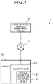
- Fig. 1 is a schematic view of a road surface profile estimation system 1 according to a first embodiment of the present invention.
- the road surface profile estimation system 1 includes a vehicle 30, an accelerometer 21 that measures vertical acceleration relative to a road surface with which the vehicle 30 is in contact, an angular velocity meter 22 that measures angular velocity about a pitch axis of the vehicle 30, and a road surface profile estimation device 10 that estimates the profile of the road surface along which the vehicle 30 is traveling.
- the accelerometer 21 and the angular velocity meter 22 are built into a smartphone 20.
- the smartphone 20 may be disposed in any desired location, such as on the dashboard or in the trunk of the vehicle 30.
- the accelerometer 21 and the angular velocity meter 22 may also be disposed in the vehicle 30 independently.
- the accelerometer 21 measures vertical acceleration relative to the road surface with which the vehicle 30 is in contact, but does not necessarily have to measure only vertical acceleration and may also measure horizontal acceleration relative to the road surface.
- the accelerometer 21 is to measure at least the vertical component relative to the road surface.
- the angular velocity meter 22 measures angular velocity about the pitch axis of the vehicle 30 but does not necessarily have to measure only the angular velocity about the pitch axis and may also measure angular velocity about a roll axis and angular velocity about a yaw axis of the vehicle 30.
- the angular velocity meter 22 is to measure at least the angular velocity about the pitch axis.
- the road surface profile estimation device 10 estimates the profile of the road surface along which the vehicle 30 is traveling on the basis of the acceleration and angular velocity measured by the accelerometer 21 and the angular velocity meter 22, and so on.
- the road surface profile estimation device 10 is connected to the smartphone 20 over a communication network N.
- the communication network N may be a wired or wireless communication network.
- the road surface profile estimation device 10 does not necessarily have to be independent of the smartphone 20 and may be formed integrally with the smartphone 20.
- the smartphone 20 may be caused to function as the road surface profile estimation device 10 by executing a road surface profile estimation program installed in the smartphone 20.
- the vehicle 30 may be an automobile that travels along a road surface on the tires of four wheels. Needless to mention, the vehicle 30 may also be a three-wheel or two-wheel vehicle and may also have five or more wheels. An automobile of any size may be used as the vehicle 30, and in this specification, cases in which a light vehicle (Light), a small vehicle (Small), and a middle-sized vehicle (Middle) are used as the vehicle 30 will be described.
- a light vehicle Light
- Small small vehicle
- Middle middle-sized vehicle
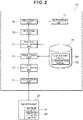
- Fig. 2 is a function block diagram of the road surface profile estimation device 10 according to the first embodiment of the present invention.
- the road surface profile estimation device 10 includes an acquisition unit 11, a first calculation unit 12, a prediction unit 13, a second calculation unit 14, an updating unit 15, a smoothing unit 16, an estimation unit 17, and a storage unit 18.
- the acquisition unit 11 acquires the vertical acceleration relative to the road surface with which the vehicle 30 is in contact and the angular velocity about the pitch axis of the vehicle 30.
- the acquisition unit 11 may acquire the acceleration and the angular velocity from the accelerometer 21 and the angular velocity meter 22 built into the smartphone 20 by communicating with the smartphone 20.
- the first calculation unit 12 calculates a vertical displacement by integrating the acceleration and calculates an angular displacement about the pitch axis by integrating the angular velocity.
- the first calculation unit 12 calculates the vertical displacement by executing second order integration relative to time on the acceleration acquired by the acquisition unit 11. Further, the first calculation unit 12 calculates the angular displacement about the pitch axis by executing first order integration relative to time on the angular velocity acquired by the acquisition unit 11.
- the prediction unit 13 predicts the time evolution of state variables including variables expressing unevenness on the road surface along which the vehicle 30 is traveling, variable expressing up-down motion of the vehicle 30, and variables expressing rotary motion of the vehicle 30 about the pitch axis on the basis of a simulation model M1.
- the simulation model M1 is stored in the storage unit 18.
- the simulation model M1 is a half car model of the vehicle 30, and the state variables are variables expressing states of the half car model. More specifically, the variables expressing unevenness on the road surface include the vertical displacement and speed of a front tire of the half car model, and the vertical displacement and speed of a rear tire of the half car model.
- variables expressing the up-down motion of the vehicle 30 include the vertical displacement and speed of the center of gravity of the half car model, the vertical displacement and speed of a front suspension of the half car model, and the vertical displacement and speed of a rear suspension of the half car model.
- variables expressing the rotary motion of the vehicle 30 about the pitch axis include an angle of rotation and an angular velocity about a pitch axis passing through the center of gravity of the half car model.
- the second calculation unit 14 calculates the vertical acceleration relative to the road surface with which the vehicle 30 is in contact, the angular velocity about the pitch axis, the vertical displacement, and the angular displacement about the pitch axis from the state variables predicted by the prediction unit 13 on the basis of an observation model M2.
- the observation model M2 is stored in the storage unit 18.
- the updating unit 15 updates the state variables by data-assimilating the acceleration and angular velocity acquired by the acquisition unit 11 and the displacement and angular displacement calculated by the first calculation unit 12 with the acceleration, angular velocity, displacement, and angular displacement calculated by the second calculation unit 14.
- data assimilation denotes processing for improving the prediction precision by updating the state variables predicted using the simulation model M1 on the basis of actual measured values. A specific example of data assimilation will be described in detail below.
- the smoothing unit 16 smooths the state variables on the basis of the acceleration and angular velocity acquired by the acquisition unit 11 and the displacement and angular displacement calculated by the first calculation unit 12 following prediction by the prediction unit 13.
- the estimation unit 17 estimates the road surface profile on the basis of the variables expressing unevenness on the road surface, included in the state variables.
- the road surface profile denotes the longitudinal shape of the road surface.
- the storage unit 18 stores the simulation model M1 and the observation model M2.
- the simulation model M1 is a model expressing the time evolution of the state variables by a linear transformation of the state variables and Gaussian noise
- the observation model M2 is a model for calculating the vertical acceleration relative to the road surface with which the vehicle 30 is in contact, the angular velocity about the pitch axis of the vehicle 30, the vertical displacement, and the angular displacement about the pitch axis from a linear transformation of the state variables and Gaussian noise.
- the updating unit 15 updates the state variables so as to minimize a square error of the state variables.
- the prediction unit 13, second calculation unit 14, and updating unit 15 of the road surface profile estimation device 10 according to this embodiment together function as a Kalman filter.
- Fig. 3 is a conceptual diagram of the simulation model M1 used by the road surface profile estimation device 10 according to the first embodiment of the present invention.
- the simulation model M1 is a half car model including 12 state variables and 13 parameters.
- the state variables include a vertical displacement h f and a vertical speed dhf/dt of the front tire of the half car model, a vertical displacement h r and a vertical speed dh r /dt of the rear tire of the half car model, a vertical displacement u b and a vertical speed du b /dt of the center of gravity of the half car model, a vertical displacement u f and a vertical speed du f /dt of the front suspension of the half car model, a vertical displacement u r and a vertical speed du r /dt of the rear suspension of the half car model, and an angle of rotation ⁇ and an angular velocity d ⁇ /dt about a pitch axis passing through the center of gravity of the half car model.
- the parameters include a spring constant ktf of the front tire of the half car model, a mass m f of the front tire, a spring constant k f and a damping coefficient c f of the front suspension, a spring constant k tr of the rear tire of the half car model, a mass m r of the rear tire, a spring constant k r and a damping coefficient c r of the rear suspension, a mass m b and a moment of inertia I y about the pitch axis of the vehicle body of the half car model, a horizontal distance L f from the center of gravity of the half car model to a ground contact point of the front tire, a horizontal distance L r from the center of gravity of the half car model to a ground contact point of the rear tire, and a horizontal distance d from the ground contact point of the front tire to a disposal point of the accelerometer 21 and the angular velocity meter 22.
- the operating state of the vehicle 30 can be expressed more accurately than when a quarter car model is used, and as a result, the time evolution of the state variables can be predicted with a higher degree of precision.
- Fig. 4 is a flowchart of first processing executed by the road surface profile estimation device 10 according to the first embodiment of the present invention.
- the first processing is processing executed by the road surface profile estimation device 10 to data-assimilate the state variables with measured values using a Kalman filter.
- the road surface profile estimation device 10 uses the acquisition unit 11 to acquire the vertical acceleration relative to the road surface with which the vehicle 30 is in contact and the angular velocity about the pitch axis of the vehicle 30 (S10). Measurement of the acceleration by the accelerometer 21 and measurement of the angular velocity by the angular velocity meter 22 may be performed at predetermined time intervals. The acquisition unit 11 may acquire the acceleration and the angular velocity every time measurement is performed by the accelerometer 21 and the angular velocity meter 22 or acquire the acceleration and the angular velocity together once measurement is complete.
- the first calculation unit 12 calculates a vertical displacement by integrating the acceleration acquired by the acquisition unit 11, and calculates an angular displacement about the pitch axis by integrating the angular velocity (S11).
- the acceleration and angular velocity acquired by the acquisition unit 11 and the displacement and angular displacement calculated by the first calculation unit 12 are expressed together by a vector y.
- the prediction unit 13 predicts the time evolution of the state variables on the basis of the half car model (S12).
- the time evolution of the state variables is determined on the basis of an equation of motion expressed by formula (1) below.
- M U ⁇ t + C U ⁇ t + KU t P t
- a vector U is expressed by formula (2) below.
- the vector U includes, as vector components, the vertical displacement u b of the center of gravity of the half car model, the angular displacement ⁇ about the pitch axis passing through the center of gravity, the vertical displacement u f of the front suspension of the half car model, and the vertical displacement u r of the rear suspension of the half car model.
- U u b ⁇ u f u r T
- matrices M, C, and K which are given respectively by following formulae (3) to (5), are parameter-dependent quantities.
- M m 0 0 0 0 I y 0 0 0 0 m f 0 0 0 0 m r
- the 12 state variables are expressed by a vector x a .
- x a u b ⁇ u f u r u ⁇ b ⁇ ⁇ u ⁇ f u ⁇ r h f h r h ⁇ f h ⁇ r T
- the prediction unit 13 expresses an error that may occur when the behavior of the vehicle 30 is modeled using a half car model in the form of a noise term.
- a matrix A a on the right side expresses the time evolution of the state variables, expressed by formula (1), as a linear transformation in time step units.
- a a exp(A ⁇ t)
- A is expressed by formula (9) below. Note that ⁇ t expresses a unit time step.
- A O 4 ⁇ 4 I 4 ⁇ 4 O 4 ⁇ 2 ⁇ M ⁇ 1 K ⁇ M ⁇ 1 C Z 4 ⁇ 4 O 2 ⁇ 2 O 2 ⁇ 2 T 4 ⁇ 4
- the matrices M, C, and K are those shown in formulae (3) to (5).
- I 4 ⁇ 4 is a 4 ⁇ 4 unit matrix
- the matrices O 4 ⁇ 4 , O 4 ⁇ 2 , and O 2 ⁇ 2 are 4 ⁇ 4, 4 ⁇ 2, and 2 ⁇ 2 zero matrices, respectively.
- a matrix Z is a quantity expressed by formula (10) below
- ⁇ k on the right side of formula (8) is the noise term in the time step k.
- the noise term ⁇ k as expressed by formula (12) below, includes an eight-dimensional vector w k and a four-dimensional vector ⁇ k .
- ⁇ k w k ⁇ k
- the noise term w k with respect to the vertical displacement u b and vertical speed du b /dt of the center of gravity of the half car model, the vertical displacement u f and vertical speed du f /dt of the front suspension of the half car model, the vertical displacement u r and vertical speed du r /dt of the rear suspension of the half car model, and the angle of rotation ⁇ and the angular velocity d ⁇ /dt about the pitch axis passing through the center of gravity of the half car model is Gaussian noise with a mean of 0 and a variance-covariance matrix of Q.
- ⁇ k, l represents the Kronecker delta.
- E w k w l T Q ⁇ k , l
- the noise term ⁇ k is Gaussian noise with a mean of 0 and a variance-covariance matrix of S.
- E ⁇ k ⁇ l T S ⁇ k , l
- the second calculation unit 14 calculates the acceleration, the angular velocity, the displacement, and the angular displacement from the state variables predicted by the prediction unit 13 on the basis of the observation model M2 (S13).
- the second calculation unit 14 calculates a vector y gathering together the acceleration, the angular velocity, the displacement, and the angular displacement from the state variables x a predicted by the prediction unit 13 on the basis of the observation model M2, which is expressed by formula (16) below.
- the second calculation unit 14 models observation using a linear transformation C a of the state variables and models an observation error using a noise term v k .
- y k C a x k a + v k
- the matrix C1 is given by formula (18) below.
- noise term v k on the right side of formula (14) is Gaussian noise with a mean of 0 and a variance-covariance matrix of R.
- the updating unit 15 updates the state variables using an optimal Kalman gain (S14).
- the optimal Kalman gain is an updating coefficient determined so as to minimize the square error of the state variables, and is given by formula (20) below.
- G k + 1 P k + 1 ⁇ C a T C a P k + 1 ⁇ C a T + R k + 1 ⁇ 1
- P k+1 - on the right side of formula (20) is the variance of the pre-update state variables in the time step k+1.
- An initial value of an expected value of the state variables is given by formula (21) below, and an initial value of the variance is given by formula (22) below.
- the state variables x a with a hat symbol attached thereto express estimated values.
- the updating unit 15 determines the expected value of the updated state variables x a using formula (25) below.
- x ⁇ k + 1 a x ⁇ k + 1 a ⁇ + G k + 1 y k + 1 ⁇ C a x ⁇ k + 1 a ⁇
- y k+1 on the right side expresses the acceleration and angular velocity acquired by the acquisition unit 11 and the displacement and angular displacement calculated by the first calculation unit 12 in the time step k+1, and is an actual measured value acquired in relation to the vehicle 30.
- the second term on the right side is a term for correcting the state variables using a value obtained by multiplying an optimal Kalman gain G k+1 by a difference between the measured values y k+1 and observed values calculated from the state values x k+1 a- .
- the updating unit 15 determines the variance of the updated state variables x a using formula (26) below.
- P k + 1 I ⁇ G k + 1 C a P k + 1 ⁇
- the state variables can be estimated with a high degree of precision.
- the time evolution of the state variables using the simulation model M1 including a linear transformation and Gaussian noise, and expressing observation using the observation model M2 including a linear transformation and Gaussian noise, the road surface profile can be estimated by comparatively low-load calculation.
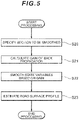
- Fig. 5 is a flowchart of second processing executed by the road surface profile estimation device 10 according to the first embodiment of the present invention.
- the second processing is processing executed by the road surface profile estimation device 10 to estimate the road surface profile by implementing smoothing processing on the state variables.
- the smoothing unit 16 receives specification of a section in which smoothing is to be implemented (S20).
- the smoothing unit 16 may use all subsequent state variables x k+1 , x k+2 , ..., x T .
- a section L (where L is an arbitrary natural number) may be specified, and the state variables may be smoothed using x k+1 , x k+2 , ..., x k+L .
- the smoothing unit 16 initializes an expected value of the smoothed state variables using formula (27) below, and initializes a variance of the smoothed state variables using formula (28) below.
- x ⁇ N x ⁇ N a
- P N b P N
- the smoothing unit 16 calculates a gain ⁇ of back propagation during the smoothing processing using formula (29) below (S21).
- ⁇ k P k A a P k + 1 ⁇ ⁇ 1
- x ⁇ k x ⁇ k a + ⁇ k x ⁇ k + 1 ⁇ x ⁇ k + 1 a ⁇ 1
- P k b P k ⁇ ⁇ k P k + 1 ⁇ ⁇ P k + 1 b ⁇ k T
- the estimation unit 17 estimates the profile of the road surface on the basis of the variables expressing the unevenness of the road surface, included in the state variables (S23). More specifically, the estimation unit 17 estimates the profile of the road surface on the basis of the vertical displacement h f of the front tire of the half car model and the vertical displacement h r of the rear tire of the half car model.
- the road surface profile estimation device 10 by employing in data assimilation not only the vertical acceleration relative to the road surface with which the vehicle 30 is in contact and the angular velocity about the pitch axis of the vehicle 30 but also the vertical displacement and the angular displacement about the pitch axis, highly stable analysis can be realized, and as a result, the profile of any road surface, including that of a general road, can be estimated with a high degree of precision using a general-purpose vehicle. Moreover, by employing in data smoothing not only the vertical acceleration and the angular velocity about the pitch axis but also the vertical displacement and the angular displacement about the pitch axis, the road surface profile can be estimated with an even higher degree of precision.
- Fig. 6 is a first graph showing a relationship between a travel distance and the road surface profile, estimated by the road surface profile estimation system 1 according to the first embodiment of the present invention.
- the travel distance (Distance) is shown on the horizontal axis in units of meters (m)
- the road surface profile is shown on the vertical axis in units of meters (m).
- a road surface profile estimated by the road surface profile estimation system 1 according to this embodiment using a light vehicle (Light) is indicated by a solid line
- a road surface profile estimated using a dedicated vehicle (Profiler) is indicated by a dotted line.
- the road surface profile estimated by the road surface profile estimation system 1 according to this embodiment using a light vehicle and the road surface profile estimated using a dedicated vehicle substantially match.
- a road surface profile can be estimated with an approximately identical degree of precision to that achieved by a dedicated vehicle using a light vehicle and the smartphone 20.
- Fig. 7 is a second graph showing the relationship between the travel distance and the road surface profile, estimated by the road surface profile estimation system 1 according to the first embodiment of the present invention.
- the travel distance (Distance) is shown on the horizontal axis in units of meters (m)
- the road surface profile is shown on the vertical axis in units of meters (m).
- a road surface profile estimated by the road surface profile estimation system 1 according to this embodiment using a small vehicle (Small size) is indicated by a dot-dash line
- a road surface profile estimated using a dedicated vehicle (Profiler) is indicated by a dotted line.
- Fig. 8 is a third graph showing the relationship between the travel distance and the road surface profile, estimated by the road surface profile estimation system 1 according to the first embodiment of the present invention.
- the travel distance (Distance) is shown on the horizontal axis in units of meters (m)
- the road surface profile is shown on the vertical axis in units of meters (m).
- a road surface profile estimated by the road surface profile estimation system 1 according to this embodiment using a middle-sized vehicle (Middle size) is indicated by a dot-dot-dash line
- a road surface profile estimated using a dedicated vehicle (Profiler) is indicated by a dotted line.
- Fig. 9 is a fourth graph showing a power spectrum of the road surface profile estimated by the road surface profile estimation system 1 according to the first embodiment of the present invention.
- a frequency Frequency
- PSD power spectrum density
- the power spectrum density of the road surface profile estimated by the road surface profile estimation system 1 according to this embodiment using a light vehicle (Light) is indicated by a solid line
- the power spectrum density of the road surface profile estimated by the road surface profile estimation system 1 according to this embodiment using a small vehicle (Small size) is indicated by a dot-dash line
- the power spectrum density of the road surface profile estimated by the road surface profile estimation system 1 according to this embodiment using a middle-sized vehicle (Middle size) is indicated by a dot-dot-dash line
- the power spectrum density of the road surface profile estimated using a dedicated vehicle (Profiler) is indicated by a dotted line.
- the power spectrum density of the road surface profile estimated by the road surface profile estimation system 1 according to this embodiment substantially matches the power spectrum density of the road surface profile estimated using a dedicated vehicle.
- a road surface profile can be estimated with an approximately identical degree of precision to that achieved by a dedicated vehicle using any desired vehicle and the smartphone 20.
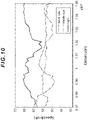
- Fig. 10 is a fifth graph showing the travel distance and the speed of the vehicle 30 during estimation of the road surface profile by the road surface profile estimation system 1 according to the first embodiment of the present invention.
- the travel distance (Distance) is shown on the horizontal axis in units of meters (m)
- the speed of the vehicle 30 is shown on the vertical axis in units of kilometers per hour (km/h).
- the speed of a light vehicle (Light) is indicated by a solid line
- the speed of a small vehicle (Small size) is indicated by a dot-dash line
- the speed of a middle-sized vehicle (Middle size) is indicated by a dot-dot-dash line.
- the respective speeds of the light vehicle, the small vehicle, and the middle-sized vehicle are not constant, and that the respective speeds vary differently over time.
- the road surface profile estimation system 1 according to this embodiment even when the speed of the vehicle 30, which is used to measure the acceleration and angular velocity, varies, the road surface profile is estimated with stability.
- a road surface profile can be estimated with a high degree of precision regardless of the size and travel speed of the vehicle 30 in which the smartphone 20 having the built-in accelerometer 21 and angular velocity meter 22 is disposed.
- the road surface profile can be estimated with a high degree of precision.
- Fig. 11 is a sixth graph showing the travel distance and the speed of the vehicle 30 during estimation of the road surface profile by the road surface profile estimation system 1 according to the first embodiment of the present invention.
- the travel distance (Distance) is shown on the horizontal axis in units of meters (m)
- the IRI which is an index of the road surface profile
- the vertical axis in units of millimeters/meter (mm/m).
- an IRI estimated by the road surface profile estimation system 1 according to this embodiment using a light vehicle (Light) is indicated by a solid line
- an IRI estimated using a dedicated vehicle is indicated by a dotted line.
- R denotes locations in which the dedicated vehicle stops for red lights
- B denotes locations in which the dedicated vehicle starts on green lights. It is evident from the sixth graph that in the locations where the dedicated vehicle starts on green lights, the IRI estimated by the road surface profile estimation system 1 according to this embodiment substantially matches the IRI estimated using the dedicated vehicle, but in the locations where the dedicated vehicle stops for red lights, the IRI estimated by the road surface profile estimation system 1 according to this embodiment diverges from the IRI estimated using the dedicated vehicle.
- the IRI estimated using the dedicated vehicle may deviate from the true value thereof immediately before and after stopping and starting.
- the IRI of the road surface can be estimated with a high degree of precision even when the vehicle 30 stops and starts.
- the profile of a road surface can be estimated with a high degree of precision even on a general road where frequent stops and starts are unavoidable.
- the simulation model M1 and observation model M2 stored in the storage unit 18 of the road surface profile estimation device 10 differ from those of the first embodiment.
- the road surface profile estimation system 1 according to the second embodiment is configured similarly to the road surface profile estimation system according to the first embodiment.
- the simulation model M1 is a model expressing the time evolution of the state variables using either a linear transformation or a non-linear transformation of the state variables and either Gaussian noise or non-Gaussian noise
- the observation model M2 is a model used to calculate the vertical acceleration relative to the road surface with which the vehicle 30 is in contact, the angular velocity about the pitch axis of the vehicle 30, the vertical displacement, and the angular displacement about the pitch axis using either a linear transformation or a non-linear transformation of the state variables and either Gaussian noise or non-Gaussian noise.
- the prediction unit 13, the second calculation unit 14, and the updating unit 15 of the road surface profile estimation device 10 according to this embodiment together function as a particle filter.
- Fig. 12 is a flowchart of third processing executed by the road surface profile estimation device 10 according to the second embodiment of the present invention.
- the third processing is processing executed by the road surface profile estimation device 10 to data-assimilate the state variables and the measured values using a particle filter.
- the road surface profile estimation device 10 uses the acquisition unit 11 to acquire the vertical acceleration relative to the road surface with which the vehicle 30 is in contact and the angular velocity about the pitch axis of the vehicle 30 (S30). Measurement of the acceleration by the accelerometer 21 and measurement of the angular velocity by the angular velocity meter 22 may be performed at predetermined time intervals. The acquisition unit 11 may acquire the acceleration and the angular velocity every time measurement is performed by the accelerometer 21 and the angular velocity meter 22 or acquire the acceleration and the angular velocity together once measurement is complete.
- the first calculation unit 12 calculates the vertical displacement by integrating the acceleration acquired by the acquisition unit 11, and calculates the angular displacement about the pitch axis by integrating the angular velocity (S31).
- the acceleration and angular velocity acquired by the acquisition unit 11 and the displacement and angular displacement calculated by the first calculation unit 12 are expressed together by the vector y.
- the prediction unit 13 predicts the time evolution of the state variables on the basis of the half car model and generates a plurality of particles on the basis of a probability distribution of the predicted state variables (S32).
- the time evolution of the state variables is determined using the simulation model M1, which is expressed by formula (32) below.
- f k is the linear transformation or non-linear transformation of the state variables x k in the time step k.
- w(k) is the noise term of the time step k and denotes Gaussian noise or non-Gaussian noise with a mean of 0.
- the prediction unit 13 generates N particles x k-1 (i) on the basis of a probability distribution p(x k-1
- ⁇ represents a delta function.
- i 1, 2, ... N.
- y 1:1 ) may be assumed to be a uniform distribution, for example, or may be set as p(x 2
- the second calculation unit 14 calculates the acceleration, the angular velocity, the displacement, and the angular displacement from the state variables predicted by the prediction unit 13 on the basis of the observation model M2, and calculates a weighting to be used during updating (S33).
- the second calculation unit 14 calculates the acceleration, angular velocity, displacement, and angular displacement y k from the state variables x k predicted by the prediction unit 13 on the basis of the observation model M2, which is expressed by formula (33) below.
- y k h k x k + ⁇ k
- h k is the linear transformation or non-linear transformation of the state variables x k in the time step k.
- v(k) is the noise term of the time step k and denotes Gaussian noise or non-Gaussian noise with a mean of 0.
- the second calculation unit 14 determines the probability distribution p(y k
- q i p y k
- x k i / ⁇ i 1 N p y k
- the updating unit 15 resamples the particles using the calculated weighting q i , and updates the probability distribution of the state variables (S34).
- the updating unit 15 determines a probability distribution p(x k
- the estimation unit 17 estimates the road surface profile on the basis of the probability distribution p(x k
- the estimation unit 17 may estimate the road surface profile by determining the expected value of the variables representing the unevenness of the road surface, included in the state variables.
- the time evolution of the state variables can be expressed using the simulation model M1 including a non-linear transformation and non-Gaussian noise, and observation can be expressed using the observation model M2 including a non-linear transformation and non-Gaussian noise.
- the observation model M2 including a non-linear transformation and non-Gaussian noise can be expressed using the observation model M2 including a non-linear transformation and non-Gaussian noise.
Landscapes
- Engineering & Computer Science (AREA)
- Physics & Mathematics (AREA)
- General Physics & Mathematics (AREA)
- Multimedia (AREA)
- Radar, Positioning & Navigation (AREA)
- Remote Sensing (AREA)
- Structural Engineering (AREA)
- Architecture (AREA)
- Civil Engineering (AREA)
- Mathematical Physics (AREA)
- Transportation (AREA)
- Mechanical Engineering (AREA)
- Automation & Control Theory (AREA)
- Control Of Driving Devices And Active Controlling Of Vehicle (AREA)
- Length Measuring Devices With Unspecified Measuring Means (AREA)
- Length Measuring Devices By Optical Means (AREA)
- Image Processing (AREA)
Description
- The present invention relates to a road surface profile estimation device, a road surface profile estimation system, a road surface profile estimation method, and a road surface profile estimation program.
- Conventionally, in order to evaluate the longitudinal shape (referred to hereafter as the road surface profile) of a road surface, unevenness on the road surface may be measured, and an index such as an IRI (International Roughness Index), for example, may be calculated. Information relating to the road surface profile may be used to determine whether the road surface requires maintenance and evaluate the comfort level when traveling by vehicle.
- Patent Publication
JP-A-2017-040486 - Patent Application
WO 98/24977 A1 - Journal article "IRI Estimation by the Frequency Domain Analysis of Vehicle Dynamic Responses and Its Large-scale Application", Mobiquitous '16 Adjunct Proceedings from November 2016 aims to disclose an improved smartphone based Dynamic Response Intelligent Monitoring System (iDRIMS) by employing frequency domain analysis. The improved algorithm for International Roughness Index (IRI) estimation consists of two steps. At first. a Half-Car (HC) model, which can reproduce both vehicle bouncing and pitching motions and represent sensor installation location in the longitudinal direction, is selected as the vehicle numerical model and identified. The vehicle parameters are identified through a drive tests over a portable hump with a known size. As opposed to previous approach of parameter identification in the time domain using Kalman filter, the parameters are optimized to minimize the difference between simulation and measured hump responses in the frequency domain using Genetic algorithm (GA). Then, IRI is estimated by measuring vertical acceleration responses of ordinary vehicles. Measured acceleration is converted to the acceleration RMS of the sprung mass of standard quarter car by multiplying a transfer function. The transfer function, estimated through the simulation of the identified HC model as opposed to QC model in previous approaches, reflects the vehicle pitching motions and sensor installation location. The RMS is further converted to IRI based on correlation between these values.
- A road surface profile may be estimated using a dedicated vehicle equipped with a high-precision laser distance meter. However, a dedicated vehicle for estimating a road surface profile is expensive, and operators capable of using the vehicle are limited. Moreover, a dedicated vehicle for estimating a road surface profile may be designed for the purpose of estimating the road surface profile of an expressway and may not always be suitable for estimating the road surface profile of a general road.
- Meanwhile, a road surface profile may be estimated by mounting a simple sensor on a general-purpose vehicle, but in this case, it may not be possible to acquire sufficient precision.
- Hence, the present invention provides a road surface profile estimation device, a road surface profile estimation system, a road surface profile estimation method, and a road surface profile estimation program with which any road surface profile, including that of a general road, can be estimated with a high degree of precision using a general-purpose vehicle.
- A road surface profile estimation device according to one aspect of the present invention includes an acquisition unit that acquires a vertical acceleration relative to a road surface with which a vehicle is in contact and angular velocity about a pitch axis of the vehicle, a first calculation unit that calculates a vertical displacement by integrating the acceleration and calculates an angular displacement about the pitch axis by integrating the angular velocity, a prediction unit that predicts, on the basis of a simulation model, a time evolution of state variables including variables expressing unevenness on a road surface along which the vehicle is traveling, variables expressing up-down motion of the vehicle, and variables expressing rotary motion about the pitch axis of the vehicle, a second calculation unit that calculates, on the basis of an observation model, the acceleration, the angular velocity, the displacement, and the angular displacement from the state variables predicted by the prediction unit, an updating unit that updates the state variables by data-assimilating the acceleration and the angular velocity acquired by the acquisition unit and the displacement and the angular displacement calculated by the first calculation unit with the acceleration, the angular velocity, the displacement, and the angular displacement calculated by the second calculation unit, and an estimation unit that estimates the road surface profile on the basis of the variables expressing the unevenness of the road surface, included in the state variables.
- According to this aspect, by employing in data assimilation not only the vertical acceleration relative to the road surface with which the vehicle is in contact and the angular velocity about the pitch axis of the vehicle but also the vertical displacement and the angular displacement about the pitch axis, highly stable analysis can be realized, and as a result, the profile of any road surface, including that of a general road, can be estimated with a high degree of precision using a general-purpose vehicle.
- The aspect described above may further include a smoothing unit that smooths the state variables on the basis of the acceleration and the angular velocity acquired by the acquisition unit and the displacement and the angular displacement calculated by the first calculation unit following a point at which the prediction unit executes prediction.
- According to this aspect, by employing in data smoothing not only the vertical acceleration of the vehicle and the angular velocity about the pitch axis of the vehicle but also the vertical displacement and the angular displacement about the pitch axis, the road surface profile can be estimated with an even higher degree of precision.
- In the aspect described above, the simulation model may be a half car model of the vehicle, and
the state variables may be variables expressing states of the half car model. - According to this aspect, the operating state of the vehicle can be expressed more accurately than when a quarter car model is used as the simulation model, and as a result, the time evolution of the state variables can be predicted with a higher degree of precision.
- In the aspect described above, the variables expressing the unevenness of the road surface may include a vertical displacement and a vertical speed of a front tire of the half car model, and a vertical displacement and a vertical speed of a rear tire of the half car model, the variables expressing the up-down motion of the vehicle may include a vertical displacement and a vertical speed of a center of gravity of the half car model, a vertical displacement and a vertical speed of a front suspension of the half car model, and a vertical displacement and a vertical speed of a rear suspension of the half car model, and the variables expressing the rotary motion about the pitch axis of the vehicle may include an angle of rotation and an angular velocity about a pitch axis passing through the center of gravity of the half car model.
- In the aspect described above, the simulation model may be a model expressing the time evolution of the state variables by a linear transformation or a non-linear transformation of the state variables and Gaussian noise or non-Gaussian noise, and the observation model may be a model for calculating the acceleration, the angular velocity, the displacement, and the angular displacement using a linear transformation or a non-linear transformation of the state variables and Gaussian noise or non-Gaussian noise.
- According to this aspect, by expressing the time evolution of the state variables using a simulation model that includes a non-linear transformation and non-Gaussian noise and expressing observation using an observation model that includes a non-linear transformation and non-Gaussian noise, non-linear behavior and non-Gaussian vibration can be described accurately, and as a result, the road surface profile can be estimated with an even higher degree of precision.
- In the aspect described above, the simulation model may be a model expressing the time evolution of the state variables by a linear transformation of the state variables and Gaussian noise, the observation model may be a model for calculating the acceleration, the angular velocity, the displacement, and the angular displacement using a linear transformation of the state variables and Gaussian noise, and the updating unit may update the state variables so as to minimize a square error of the state variables.
- According to this aspect, by expressing the time evolution of the state variables using a simulation model that includes a linear transformation and Gaussian noise and expressing observation using an observation model that includes a linear transformation and Gaussian noise, the road surface profile can be estimated by comparatively low-load calculation.
- A road surface profile estimation system according to another aspect of the present invention includes an accelerometer disposed in a vehicle in order to measure a vertical acceleration relative to a road surface with which the vehicle is in contact, an angular velocity meter disposed in the vehicle in order to measure an angular velocity about a pitch axis of the vehicle, and a road surface profile estimation device for estimating a profile of a road surface along which the vehicle is traveling, the road surface profile estimation device including an acquisition unit that acquires the acceleration from the accelerometer and the angular velocity from the angular velocity meter, a first calculation unit that calculates a vertical displacement by integrating the acceleration and calculates an angular displacement about the pitch axis by integrating the angular velocity, a prediction unit that predicts, on the basis of a simulation model, a time evolution of state variables including variables expressing unevenness on the road surface along which the vehicle is traveling, variables expressing up-down motion of the vehicle, and variables expressing rotary motion about the pitch axis of the vehicle, a second calculation unit that calculates, on the basis of an observation model, the acceleration, the angular velocity, the displacement, and the angular displacement from the state variables predicted by the prediction unit, an updating unit that updates the state variables by data-assimilating the acceleration and the angular velocity acquired by the acquisition unit and the displacement and the angular displacement calculated by the first calculation unit with the acceleration, the angular velocity, the displacement, and the angular displacement calculated by the second calculation unit, and an estimation unit that estimates the road surface profile on the basis of the variables expressing the unevenness of the road surface, included in the state variables.
- According to this aspect, by employing in data assimilation not only the vertical acceleration relative to the road surface with which the vehicle is in contact and the angular velocity about the pitch axis of the vehicle but also the vertical displacement and the angular displacement about the pitch axis, highly stable analysis can be realized, and as a result, the profile of any road surface, including that of a general road, can be estimated with a high degree of precision using a general-purpose vehicle.
- A method of estimating a road surface profile according to a further aspect of the present invention includes a first step of acquiring a vertical acceleration relative to a road surface with which a vehicle is in contact and angular velocity about a pitch axis of the vehicle, a second step of calculating a vertical displacement by integrating the acceleration and calculating an angular displacement about the pitch axis by integrating the angular velocity, a third step of predicting, on the basis of a simulation model, a time evolution of state variables including variables expressing unevenness on a road surface along which the vehicle is traveling, variables expressing up-down motion of the vehicle, and variables expressing rotary motion about the pitch axis of the vehicle, a fourth step of calculating, on the basis of an observation model, the acceleration, the angular velocity, the displacement, and the angular displacement from the state variables predicted in the third step, a fifth step of updating the state variables by data-assimilating the acceleration and the angular velocity acquired in the first step and the displacement and the angular displacement calculated in the second step with the acceleration, the angular velocity, the displacement, and the angular displacement calculated in the fourth step, and a sixth step of estimating the road surface profile on the basis of the variables expressing the unevenness of the road surface, included in the state variables.
- According to this aspect, by employing in data assimilation not only the vertical acceleration relative to the road surface with which the vehicle is in contact and the angular velocity about the pitch axis of the vehicle but also the vertical displacement and the angular displacement about the pitch axis, highly stable analysis can be realized, and as a result, the profile of any road surface, including that of a general road, can be estimated with a high degree of precision using a general-purpose vehicle.
- A road surface profile estimation program according to a further aspect of the present invention causes a computer provided in a road surface profile estimation device to function as an acquisition unit that acquires a vertical acceleration relative to a road surface with which a vehicle is in contact and angular velocity about a pitch axis of the vehicle, a first calculation unit that calculates a vertical displacement by integrating the acceleration and calculates an angular displacement about the pitch axis by integrating the angular velocity, a prediction unit that predicts, on the basis of a simulation model, a time evolution of state variables including variables expressing unevenness on a road surface along which the vehicle is traveling, variables expressing up-down motion of the vehicle, and variables expressing rotary motion about the pitch axis of the vehicle, a second calculation unit that calculates, on the basis of an observation model, the acceleration, the angular velocity, the displacement, and the angular displacement from the state variables predicted by the prediction unit, an updating unit that updates the state variables by data-assimilating the acceleration and the angular velocity acquired by the acquisition unit and the displacement and the angular displacement calculated by the first calculation unit with the acceleration, the angular velocity, the displacement, and the angular displacement calculated by the second calculation unit, and an estimation unit that estimates the road surface profile on the basis of the variables expressing the unevenness of the road surface, included in the state variables.
- According to this aspect, by employing in data assimilation not only the vertical acceleration relative to the road surface with which the vehicle is in contact and the angular velocity about the pitch axis of the vehicle but also the vertical displacement and the angular displacement about the pitch axis, highly stable analysis can be realized, and as a result, the profile of any road surface, including that of a general road, can be estimated with a high degree of precision using a general-purpose vehicle.
- According to the present invention, it is possible to provide a road surface profile estimation device, a road surface profile estimation system, a road surface profile estimation method, and a road surface profile estimation program with which any road surface profile, including that of a general road, can be estimated with a high degree of precision using a general-purpose vehicle.
-
-
Fig. 1 is a schematic view of a road surface profile estimation system according to a first embodiment of the present invention. -
Fig. 2 is a function block diagram of a road surface profile estimation device according to the first embodiment of the present invention. -
Fig. 3 is a conceptual diagram of a simulation model used by the road surface profile estimation device according to the first embodiment of the present invention. -
Fig. 4 is a flowchart of first processing executed by the road surface profile estimation device according to the first embodiment of the present invention. -
Fig. 5 is a flowchart of second processing executed by the road surface profile estimation device according to the first embodiment of the present invention. -
Fig. 6 is a first graph showing a relationship between a travel distance and a road surface profile, estimated by the road surface profile estimation system according to the first embodiment of the present invention. -
Fig. 7 is a second graph showing the relationship between the travel distance and the road surface profile, estimated by the road surface profile estimation system according to the first embodiment of the present invention. -
Fig. 8 is a third graph showing the relationship between the travel distance and the road surface profile, estimated by the road surface profile estimation system according to the first embodiment of the present invention. -
Fig. 9 is a fourth graph showing a power spectrum of the road surface profile estimated by the road surface profile estimation system according to the first embodiment of the present invention. -
Fig. 10 is a fifth graph showing the travel distance and the speed of a vehicle during estimation of the road surface profile by the road surface profile estimation system according to the first embodiment of the present invention. -
Fig. 11 is a sixth graph showing the travel distance and the speed of the vehicle during estimation of the road surface profile by the road surface profile estimation system according to the first embodiment of the present invention. -
Fig. 12 is a flowchart of third processing executed by a road surface profile estimation device according to a second embodiment of the present invention. - Embodiments of the present invention will be described below with reference to the attached figures. Note that in the figures, components with identical reference numerals have identical or similar configurations.
-
Fig. 1 is a schematic view of a road surfaceprofile estimation system 1 according to a first embodiment of the present invention. The road surfaceprofile estimation system 1 includes avehicle 30, anaccelerometer 21 that measures vertical acceleration relative to a road surface with which thevehicle 30 is in contact, anangular velocity meter 22 that measures angular velocity about a pitch axis of thevehicle 30, and a road surfaceprofile estimation device 10 that estimates the profile of the road surface along which thevehicle 30 is traveling. In the road surfaceprofile estimation system 1 according to this embodiment, theaccelerometer 21 and theangular velocity meter 22 are built into asmartphone 20. Thesmartphone 20 may be disposed in any desired location, such as on the dashboard or in the trunk of thevehicle 30. Needless to mention, theaccelerometer 21 and theangular velocity meter 22 may also be disposed in thevehicle 30 independently. Theaccelerometer 21 measures vertical acceleration relative to the road surface with which thevehicle 30 is in contact, but does not necessarily have to measure only vertical acceleration and may also measure horizontal acceleration relative to the road surface. Of the plurality of components of the acceleration of thevehicle 30, theaccelerometer 21 is to measure at least the vertical component relative to the road surface. Theangular velocity meter 22 measures angular velocity about the pitch axis of thevehicle 30 but does not necessarily have to measure only the angular velocity about the pitch axis and may also measure angular velocity about a roll axis and angular velocity about a yaw axis of thevehicle 30. Of the angular velocities relative to the plurality of axes of thevehicle 30, theangular velocity meter 22 is to measure at least the angular velocity about the pitch axis. - The road surface
profile estimation device 10 estimates the profile of the road surface along which thevehicle 30 is traveling on the basis of the acceleration and angular velocity measured by theaccelerometer 21 and theangular velocity meter 22, and so on. In the road surfaceprofile estimation system 1 according to this embodiment, the road surfaceprofile estimation device 10 is connected to thesmartphone 20 over a communication network N. Here, the communication network N may be a wired or wireless communication network. Note that the road surfaceprofile estimation device 10 does not necessarily have to be independent of thesmartphone 20 and may be formed integrally with thesmartphone 20. In this case, thesmartphone 20 may be caused to function as the road surfaceprofile estimation device 10 by executing a road surface profile estimation program installed in thesmartphone 20. - The
vehicle 30 may be an automobile that travels along a road surface on the tires of four wheels. Needless to mention, thevehicle 30 may also be a three-wheel or two-wheel vehicle and may also have five or more wheels. An automobile of any size may be used as thevehicle 30, and in this specification, cases in which a light vehicle (Light), a small vehicle (Small), and a middle-sized vehicle (Middle) are used as thevehicle 30 will be described. -
Fig. 2 is a function block diagram of the road surfaceprofile estimation device 10 according to the first embodiment of the present invention. The road surfaceprofile estimation device 10 includes anacquisition unit 11, afirst calculation unit 12, aprediction unit 13, asecond calculation unit 14, an updatingunit 15, a smoothingunit 16, anestimation unit 17, and astorage unit 18. - The
acquisition unit 11 acquires the vertical acceleration relative to the road surface with which thevehicle 30 is in contact and the angular velocity about the pitch axis of thevehicle 30. Theacquisition unit 11 may acquire the acceleration and the angular velocity from theaccelerometer 21 and theangular velocity meter 22 built into thesmartphone 20 by communicating with thesmartphone 20. - The
first calculation unit 12 calculates a vertical displacement by integrating the acceleration and calculates an angular displacement about the pitch axis by integrating the angular velocity. Thefirst calculation unit 12 calculates the vertical displacement by executing second order integration relative to time on the acceleration acquired by theacquisition unit 11. Further, thefirst calculation unit 12 calculates the angular displacement about the pitch axis by executing first order integration relative to time on the angular velocity acquired by theacquisition unit 11. - The
prediction unit 13 predicts the time evolution of state variables including variables expressing unevenness on the road surface along which thevehicle 30 is traveling, variable expressing up-down motion of thevehicle 30, and variables expressing rotary motion of thevehicle 30 about the pitch axis on the basis of a simulation model M1. Here, the simulation model M1 is stored in thestorage unit 18. In this embodiment, the simulation model M1 is a half car model of thevehicle 30, and the state variables are variables expressing states of the half car model. More specifically, the variables expressing unevenness on the road surface include the vertical displacement and speed of a front tire of the half car model, and the vertical displacement and speed of a rear tire of the half car model. Further, the variables expressing the up-down motion of thevehicle 30 include the vertical displacement and speed of the center of gravity of the half car model, the vertical displacement and speed of a front suspension of the half car model, and the vertical displacement and speed of a rear suspension of the half car model. Furthermore, the variables expressing the rotary motion of thevehicle 30 about the pitch axis include an angle of rotation and an angular velocity about a pitch axis passing through the center of gravity of the half car model. - The
second calculation unit 14 calculates the vertical acceleration relative to the road surface with which thevehicle 30 is in contact, the angular velocity about the pitch axis, the vertical displacement, and the angular displacement about the pitch axis from the state variables predicted by theprediction unit 13 on the basis of an observation model M2. The observation model M2 is stored in thestorage unit 18. - The updating
unit 15 updates the state variables by data-assimilating the acceleration and angular velocity acquired by theacquisition unit 11 and the displacement and angular displacement calculated by thefirst calculation unit 12 with the acceleration, angular velocity, displacement, and angular displacement calculated by thesecond calculation unit 14. Here, data assimilation denotes processing for improving the prediction precision by updating the state variables predicted using the simulation model M1 on the basis of actual measured values. A specific example of data assimilation will be described in detail below. - The smoothing
unit 16 smooths the state variables on the basis of the acceleration and angular velocity acquired by theacquisition unit 11 and the displacement and angular displacement calculated by thefirst calculation unit 12 following prediction by theprediction unit 13. - The
estimation unit 17 estimates the road surface profile on the basis of the variables expressing unevenness on the road surface, included in the state variables. Here, the road surface profile denotes the longitudinal shape of the road surface. - The
storage unit 18 stores the simulation model M1 and the observation model M2. In the road surfaceprofile estimation device 10 according to this embodiment, the simulation model M1 is a model expressing the time evolution of the state variables by a linear transformation of the state variables and Gaussian noise, while the observation model M2 is a model for calculating the vertical acceleration relative to the road surface with which thevehicle 30 is in contact, the angular velocity about the pitch axis of thevehicle 30, the vertical displacement, and the angular displacement about the pitch axis from a linear transformation of the state variables and Gaussian noise. Further, the updatingunit 15 updates the state variables so as to minimize a square error of the state variables. As will be described in detail below, theprediction unit 13,second calculation unit 14, and updatingunit 15 of the road surfaceprofile estimation device 10 according to this embodiment together function as a Kalman filter. -
Fig. 3 is a conceptual diagram of the simulation model M1 used by the road surfaceprofile estimation device 10 according to the first embodiment of the present invention. The simulation model M1 is a half car model including 12 state variables and 13 parameters. - The state variables include a vertical displacement hf and a vertical speed dhf/dt of the front tire of the half car model, a vertical displacement hr and a vertical speed dhr/dt of the rear tire of the half car model, a vertical displacement ub and a vertical speed dub/dt of the center of gravity of the half car model, a vertical displacement uf and a vertical speed duf/dt of the front suspension of the half car model, a vertical displacement ur and a vertical speed dur/dt of the rear suspension of the half car model, and an angle of rotation θ and an angular velocity dθ/dt about a pitch axis passing through the center of gravity of the half car model.
- The parameters include a spring constant ktf of the front tire of the half car model, a mass mf of the front tire, a spring constant kf and a damping coefficient cf of the front suspension, a spring constant ktr of the rear tire of the half car model, a mass mr of the rear tire, a spring constant kr and a damping coefficient cr of the rear suspension, a mass mb and a moment of inertia Iy about the pitch axis of the vehicle body of the half car model, a horizontal distance Lf from the center of gravity of the half car model to a ground contact point of the front tire, a horizontal distance Lr from the center of gravity of the half car model to a ground contact point of the rear tire, and a horizontal distance d from the ground contact point of the front tire to a disposal point of the
accelerometer 21 and theangular velocity meter 22. - By employing a half car model as the simulation model M1, the operating state of the
vehicle 30 can be expressed more accurately than when a quarter car model is used, and as a result, the time evolution of the state variables can be predicted with a higher degree of precision. -
Fig. 4 is a flowchart of first processing executed by the road surfaceprofile estimation device 10 according to the first embodiment of the present invention. The first processing is processing executed by the road surfaceprofile estimation device 10 to data-assimilate the state variables with measured values using a Kalman filter. - The road surface
profile estimation device 10 uses theacquisition unit 11 to acquire the vertical acceleration relative to the road surface with which thevehicle 30 is in contact and the angular velocity about the pitch axis of the vehicle 30 (S10). Measurement of the acceleration by theaccelerometer 21 and measurement of the angular velocity by theangular velocity meter 22 may be performed at predetermined time intervals. Theacquisition unit 11 may acquire the acceleration and the angular velocity every time measurement is performed by theaccelerometer 21 and theangular velocity meter 22 or acquire the acceleration and the angular velocity together once measurement is complete. - The
first calculation unit 12 calculates a vertical displacement by integrating the acceleration acquired by theacquisition unit 11, and calculates an angular displacement about the pitch axis by integrating the angular velocity (S11). The acceleration and angular velocity acquired by theacquisition unit 11 and the displacement and angular displacement calculated by thefirst calculation unit 12 are expressed together by a vector y. - The
prediction unit 13 predicts the time evolution of the state variables on the basis of the half car model (S12). The time evolution of the state variables is determined on the basis of an equation of motion expressed by formula (1) below.
- Here, a vector U is expressed by formula (2) below. The vector U includes, as vector components, the vertical displacement ub of the center of gravity of the half car model, the angular displacement θ about the pitch axis passing through the center of gravity, the vertical displacement uf of the front suspension of the half car model, and the vertical displacement ur of the rear suspension of the half car model.

- Further, matrices M, C, and K, which are given respectively by following formulae (3) to (5), are parameter-dependent quantities.


- Furthermore, the right side of formula (1) is given by a vector P that is dependent on the variables expressing the unevenness of the road surface. The vector P is given by formula (6) below:

- In the following description, as indicated by formula (7), the 12 state variables are expressed by a vector xa.

- The
prediction unit 13 expresses an error that may occur when the behavior of thevehicle 30 is modeled using a half car model in the form of a noise term. Theprediction unit 13 determines the time evolution of the state variables xa using the following formula (8).
- Here, subscript affixes "k" and "k+1" attached to the state variables xa express time steps. A matrix Aa on the right side expresses the time evolution of the state variables, expressed by formula (1), as a linear transformation in time step units. When Aa is expressed as Aa = exp(AΔt), A is expressed by formula (9) below. Note that Δt expresses a unit time step.

- Here, the matrices M, C, and K are those shown in formulae (3) to (5). I4 × 4 is a 4 × 4 unit matrix, and the matrices O4 × 4, O4 × 2, and O2 × 2 are 4 × 4, 4 × 2, and 2 × 2 zero matrices, respectively. Further, a matrix Z is a quantity expressed by formula (10) below, while a matrix T is a quantity expressed by formula (11) below.


- Further, ζk on the right side of formula (8) is the noise term in the time step k. The noise term ζk, as expressed by formula (12) below, includes an eight-dimensional vector wk and a four-dimensional vector ηk.
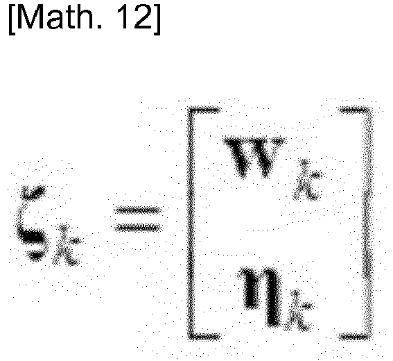
- In the noise term ζk, the noise term wk with respect to the vertical displacement ub and vertical speed dub/dt of the center of gravity of the half car model, the vertical displacement uf and vertical speed duf/dt of the front suspension of the half car model, the vertical displacement ur and vertical speed dur/dt of the rear suspension of the half car model, and the angle of rotation θ and the angular velocity dθ/dt about the pitch axis passing through the center of gravity of the half car model is Gaussian noise with a mean of 0 and a variance-covariance matrix of Q. Note that δk, l represents the Kronecker delta.

- Furthermore, in the noise term ζk, the noise term ηk with respect to the vertical displacement hf and vertical speed dhf/dt of the front tire of the half car model, and the vertical displacement hr and vertical speed dhr/dt of the rear tire of the half car model is Gaussian noise with a mean of 0 and a variance-covariance matrix of S.

- As is evident from formula (8), which expresses the time evolution of the state variables, the time evolution of the four-dimensional vector u gathering together the vertical displacement hf and vertical speed dhf/dt of the front tire of the half car model and the vertical displacement hr and vertical speed dhr/dt of the rear tire of the half car model is given by formula (15) below.

- The
second calculation unit 14 calculates the acceleration, the angular velocity, the displacement, and the angular displacement from the state variables predicted by theprediction unit 13 on the basis of the observation model M2 (S13). Thesecond calculation unit 14 calculates a vector y gathering together the acceleration, the angular velocity, the displacement, and the angular displacement from the state variables xa predicted by theprediction unit 13 on the basis of the observation model M2, which is expressed by formula (16) below. Thesecond calculation unit 14 models observation using a linear transformation Ca of the state variables and models an observation error using a noise term vk.
- Here, the linear transformation Ca is given by formula (17) below. Here, O4 is a 4 × 4 zero matrix.

- The matrix C1 is given by formula (18) below.

- Further, the noise term vk on the right side of formula (14) is Gaussian noise with a mean of 0 and a variance-covariance matrix of R.

- The updating
unit 15 updates the state variables using an optimal Kalman gain (S14). Here, the optimal Kalman gain is an updating coefficient determined so as to minimize the square error of the state variables, and is given by formula (20) below.
- Pk+1 - on the right side of formula (20) is the variance of the pre-update state variables in the time step k+1. An initial value of an expected value of the state variables is given by formula (21) below, and an initial value of the variance is given by formula (22) below. Note that the state variables xa with a hat symbol attached thereto express estimated values.


- As described above, the time evolution of the expected value of the state variables xa is given by formula (23) below.

- Here, the superscript symbol"-" indicates a pre-update quantity. Further, the time evolution of the variance of the state variables xa is given by formula (24) below.

- The updating
unit 15 determines the expected value of the updated state variables xa using formula (25) below.
- Here, "yk+1" on the right side expresses the acceleration and angular velocity acquired by the
acquisition unit 11 and the displacement and angular displacement calculated by thefirst calculation unit 12 in the time step k+1, and is an actual measured value acquired in relation to thevehicle 30. The second term on the right side is a term for correcting the state variables using a value obtained by multiplying an optimal Kalman gain Gk+1 by a difference between the measured values yk+1 and observed values calculated from the state values xk+1 a-. - The updating
unit 15 determines the variance of the updated state variables xa using formula (26) below.
- By predicting the state variables and updating the state variables in accordance with the difference with the measured values in every time step, as described above, the state variables can be estimated with a high degree of precision. By expressing the time evolution of the state variables using the simulation model M1 including a linear transformation and Gaussian noise, and expressing observation using the observation model M2 including a linear transformation and Gaussian noise, the road surface profile can be estimated by comparatively low-load calculation.
-
Fig. 5 is a flowchart of second processing executed by the road surfaceprofile estimation device 10 according to the first embodiment of the present invention. The second processing is processing executed by the road surfaceprofile estimation device 10 to estimate the road surface profile by implementing smoothing processing on the state variables. - First, the smoothing
unit 16 receives specification of a section in which smoothing is to be implemented (S20). When time steps from k = 0 to k = T exist, in order to smooth the state variables xk of a time step k, the smoothingunit 16 may use all subsequent state variables xk+1, xk+2, ..., xT. Alternatively, a section L (where L is an arbitrary natural number) may be specified, and the state variables may be smoothed using xk+1, xk+2, ..., xk+L. - The smoothing
unit 16 initializes an expected value of the smoothed state variables using formula (27) below, and initializes a variance of the smoothed state variables using formula (28) below.

- Next, the smoothing
unit 16 calculates a gain Φ of back propagation during the smoothing processing using formula (29) below (S21).
- Then, on the basis of the gain Φ, the smoothing
unit 16 smooths the expected value of the state variables back into the past from the time step k = T using formula (30) below. Further, the smoothingunit 16 smooths the variance of the state variables using formula (31) below (S22).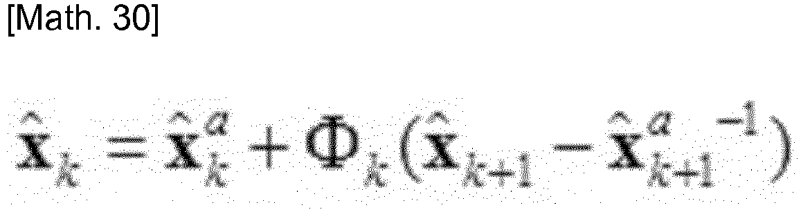

- Thus, the state variables are smoothed. Next, the
estimation unit 17 estimates the profile of the road surface on the basis of the variables expressing the unevenness of the road surface, included in the state variables (S23). More specifically, theestimation unit 17 estimates the profile of the road surface on the basis of the vertical displacement hf of the front tire of the half car model and the vertical displacement hr of the rear tire of the half car model. - With the road surface
profile estimation device 10 according to this embodiment, by employing in data assimilation not only the vertical acceleration relative to the road surface with which thevehicle 30 is in contact and the angular velocity about the pitch axis of thevehicle 30 but also the vertical displacement and the angular displacement about the pitch axis, highly stable analysis can be realized, and as a result, the profile of any road surface, including that of a general road, can be estimated with a high degree of precision using a general-purpose vehicle. Moreover, by employing in data smoothing not only the vertical acceleration and the angular velocity about the pitch axis but also the vertical displacement and the angular displacement about the pitch axis, the road surface profile can be estimated with an even higher degree of precision. -
Fig. 6 is a first graph showing a relationship between a travel distance and the road surface profile, estimated by the road surfaceprofile estimation system 1 according to the first embodiment of the present invention. In the figure, the travel distance (Distance) is shown on the horizontal axis in units of meters (m), and the road surface profile is shown on the vertical axis in units of meters (m). On the first graph, a road surface profile estimated by the road surfaceprofile estimation system 1 according to this embodiment using a light vehicle (Light) is indicated by a solid line, and a road surface profile estimated using a dedicated vehicle (Profiler) is indicated by a dotted line. It is evident from the first graph that the road surface profile estimated by the road surfaceprofile estimation system 1 according to this embodiment using a light vehicle and the road surface profile estimated using a dedicated vehicle substantially match. Hence, with the road surfaceprofile estimation system 1 according to this embodiment, a road surface profile can be estimated with an approximately identical degree of precision to that achieved by a dedicated vehicle using a light vehicle and thesmartphone 20. -
Fig. 7 is a second graph showing the relationship between the travel distance and the road surface profile, estimated by the road surfaceprofile estimation system 1 according to the first embodiment of the present invention. In the figure, the travel distance (Distance) is shown on the horizontal axis in units of meters (m), and the road surface profile is shown on the vertical axis in units of meters (m). On the second graph, a road surface profile estimated by the road surfaceprofile estimation system 1 according to this embodiment using a small vehicle (Small size) is indicated by a dot-dash line, and a road surface profile estimated using a dedicated vehicle (Profiler) is indicated by a dotted line. It is evident from the second graph that the road surface profile estimated by the road surfaceprofile estimation system 1 according to this embodiment using a small vehicle and the road surface profile estimated using a dedicated vehicle substantially match. Hence, with the road surfaceprofile estimation system 1 according to this embodiment, a road surface profile can be estimated with an approximately identical degree of precision to that achieved by a dedicated vehicle using a small vehicle and thesmartphone 20. -
Fig. 8 is a third graph showing the relationship between the travel distance and the road surface profile, estimated by the road surfaceprofile estimation system 1 according to the first embodiment of the present invention. In the figure, the travel distance (Distance) is shown on the horizontal axis in units of meters (m), and the road surface profile is shown on the vertical axis in units of meters (m). On the third graph, a road surface profile estimated by the road surfaceprofile estimation system 1 according to this embodiment using a middle-sized vehicle (Middle size) is indicated by a dot-dot-dash line, and a road surface profile estimated using a dedicated vehicle (Profiler) is indicated by a dotted line. It is evident from the third graph that the road surface profile estimated by the road surfaceprofile estimation system 1 according to this embodiment using a middle-sized vehicle and the road surface profile estimated using a dedicated vehicle substantially match. Hence, with the road surfaceprofile estimation system 1 according to this embodiment, a road surface profile can be estimated with an approximately identical degree of precision to that achieved by a dedicated vehicle using a middle-sized vehicle and thesmartphone 20. -
Fig. 9 is a fourth graph showing a power spectrum of the road surface profile estimated by the road surfaceprofile estimation system 1 according to the first embodiment of the present invention. In the figure, a frequency (Frequency) is shown on the horizontal axis in units of cycles/meter (cycle/m), and a power spectrum density (PSD) of the road surface profile is shown on the vertical axis in units of m2/(cycle/m). On the fourth graph, the power spectrum density of the road surface profile estimated by the road surfaceprofile estimation system 1 according to this embodiment using a light vehicle (Light) is indicated by a solid line, the power spectrum density of the road surface profile estimated by the road surfaceprofile estimation system 1 according to this embodiment using a small vehicle (Small size) is indicated by a dot-dash line, the power spectrum density of the road surface profile estimated by the road surfaceprofile estimation system 1 according to this embodiment using a middle-sized vehicle (Middle size) is indicated by a dot-dot-dash line, and the power spectrum density of the road surface profile estimated using a dedicated vehicle (Profiler) is indicated by a dotted line. It is evident from the fourth graph that when any of a light vehicle, a small vehicle, and a middle-sized vehicle is used, the power spectrum density of the road surface profile estimated by the road surfaceprofile estimation system 1 according to this embodiment substantially matches the power spectrum density of the road surface profile estimated using a dedicated vehicle. Hence, with the road surfaceprofile estimation system 1 according to this embodiment, a road surface profile can be estimated with an approximately identical degree of precision to that achieved by a dedicated vehicle using any desired vehicle and thesmartphone 20. -
Fig. 10 is a fifth graph showing the travel distance and the speed of thevehicle 30 during estimation of the road surface profile by the road surfaceprofile estimation system 1 according to the first embodiment of the present invention. In the figure, the travel distance (Distance) is shown on the horizontal axis in units of meters (m), and the speed of thevehicle 30 is shown on the vertical axis in units of kilometers per hour (km/h). On the fifth graph, the speed of a light vehicle (Light) is indicated by a solid line, the speed of a small vehicle (Small size) is indicated by a dot-dash line, and the speed of a middle-sized vehicle (Middle size) is indicated by a dot-dot-dash line. It is evident from the fifth graph that the respective speeds of the light vehicle, the small vehicle, and the middle-sized vehicle are not constant, and that the respective speeds vary differently over time. Hence, with the road surfaceprofile estimation system 1 according to this embodiment, even when the speed of thevehicle 30, which is used to measure the acceleration and angular velocity, varies, the road surface profile is estimated with stability. As a result, with the road surfaceprofile estimation system 1 according to this embodiment, a road surface profile can be estimated with a high degree of precision regardless of the size and travel speed of thevehicle 30 in which thesmartphone 20 having the built-inaccelerometer 21 andangular velocity meter 22 is disposed. Note that even when the location of thesmartphone 20 having the built-inaccelerometer 21 andangular velocity meter 22 is modified, by modifying the horizontal distance d from the ground contact point of the front tire to the disposal point of theaccelerometer 21 and theangular velocity meter 22, which is one of the parameters of the simulation model M1, the road surface profile can be estimated with a high degree of precision. -
Fig. 11 is a sixth graph showing the travel distance and the speed of thevehicle 30 during estimation of the road surface profile by the road surfaceprofile estimation system 1 according to the first embodiment of the present invention. In the figure, the travel distance (Distance) is shown on the horizontal axis in units of meters (m), and the IRI, which is an index of the road surface profile, is shown on the vertical axis in units of millimeters/meter (mm/m). On the sixth graph, an IRI estimated by the road surfaceprofile estimation system 1 according to this embodiment using a light vehicle (Light) is indicated by a solid line, and an IRI estimated using a dedicated vehicle is indicated by a dotted line. Further, on the sixth graph, "R" denotes locations in which the dedicated vehicle stops for red lights, and "B" denotes locations in which the dedicated vehicle starts on green lights. It is evident from the sixth graph that in the locations where the dedicated vehicle starts on green lights, the IRI estimated by the road surfaceprofile estimation system 1 according to this embodiment substantially matches the IRI estimated using the dedicated vehicle, but in the locations where the dedicated vehicle stops for red lights, the IRI estimated by the road surfaceprofile estimation system 1 according to this embodiment diverges from the IRI estimated using the dedicated vehicle. Considering that the divergence between the IRI estimated by the road surfaceprofile estimation system 1 according to this embodiment and the IRI estimated using the dedicated vehicle is concentrated in the locations where the dedicated vehicle stops and starts and that the dedicated vehicle is designed envisaging measurement during high-speed travel and may therefore be unable to estimate the IRI of the road surface precisely immediately before and after stopping and starting, the IRI estimated using the dedicated vehicle may deviate from the true value thereof immediately before and after stopping and starting. With the road surfaceprofile estimation system 1 according to this embodiment, the IRI of the road surface can be estimated with a high degree of precision even when thevehicle 30 stops and starts. Hence, with the road surfaceprofile estimation system 1 according to this embodiment, the profile of a road surface can be estimated with a high degree of precision even on a general road where frequent stops and starts are unavoidable. - In the road surface
profile estimation system 1 according to a second embodiment, the simulation model M1 and observation model M2 stored in thestorage unit 18 of the road surfaceprofile estimation device 10 differ from those of the first embodiment. With regard to all other configurations, the road surfaceprofile estimation system 1 according to the second embodiment is configured similarly to the road surface profile estimation system according to the first embodiment. In the road surfaceprofile estimation device 10 according to this embodiment, the simulation model M1 is a model expressing the time evolution of the state variables using either a linear transformation or a non-linear transformation of the state variables and either Gaussian noise or non-Gaussian noise, and the observation model M2 is a model used to calculate the vertical acceleration relative to the road surface with which thevehicle 30 is in contact, the angular velocity about the pitch axis of thevehicle 30, the vertical displacement, and the angular displacement about the pitch axis using either a linear transformation or a non-linear transformation of the state variables and either Gaussian noise or non-Gaussian noise. As will be described in detail below, theprediction unit 13, thesecond calculation unit 14, and the updatingunit 15 of the road surfaceprofile estimation device 10 according to this embodiment together function as a particle filter. -
Fig. 12 is a flowchart of third processing executed by the road surfaceprofile estimation device 10 according to the second embodiment of the present invention. The third processing is processing executed by the road surfaceprofile estimation device 10 to data-assimilate the state variables and the measured values using a particle filter. - The road surface
profile estimation device 10 uses theacquisition unit 11 to acquire the vertical acceleration relative to the road surface with which thevehicle 30 is in contact and the angular velocity about the pitch axis of the vehicle 30 (S30). Measurement of the acceleration by theaccelerometer 21 and measurement of the angular velocity by theangular velocity meter 22 may be performed at predetermined time intervals. Theacquisition unit 11 may acquire the acceleration and the angular velocity every time measurement is performed by theaccelerometer 21 and theangular velocity meter 22 or acquire the acceleration and the angular velocity together once measurement is complete. - The
first calculation unit 12 calculates the vertical displacement by integrating the acceleration acquired by theacquisition unit 11, and calculates the angular displacement about the pitch axis by integrating the angular velocity (S31). The acceleration and angular velocity acquired by theacquisition unit 11 and the displacement and angular displacement calculated by thefirst calculation unit 12 are expressed together by the vector y. - The
prediction unit 13 predicts the time evolution of the state variables on the basis of the half car model and generates a plurality of particles on the basis of a probability distribution of the predicted state variables (S32). The time evolution of the state variables is determined using the simulation model M1, which is expressed by formula (32) below.
- Here, fk is the linear transformation or non-linear transformation of the state variables xk in the time step k. Further, w(k) is the noise term of the time step k and denotes Gaussian noise or non-Gaussian noise with a mean of 0. The
prediction unit 13 generates N particles xk-1(i) on the basis of a probability distribution p(xk-1|y1:k-1), determines xk(i) by predicting the time evolution using formula (32), and determines a predicted probability distribution p(xk|y1:k-1) of the state variables in the time step k approximately using formula (33) below.
- Here, y1:k-1 represents the acceleration, angular velocity, displacement, and angular displacement measured from the time step k = 1 to the time step k-1. Further, δ represents a delta function. Furthermore, i = 1, 2, ... N. Note that an initial condition p(x1|y1:1) may be assumed to be a uniform distribution, for example, or may be set as p(x2|y1:1) = Σi=1Nδ (x2 - x2 (i))/N. Needless to mention, the initial condition does not have to be a uniform distribution, and any desired distribution may be assumed.
- The
second calculation unit 14 calculates the acceleration, the angular velocity, the displacement, and the angular displacement from the state variables predicted by theprediction unit 13 on the basis of the observation model M2, and calculates a weighting to be used during updating (S33). Thesecond calculation unit 14 calculates the acceleration, angular velocity, displacement, and angular displacement yk from the state variables xk predicted by theprediction unit 13 on the basis of the observation model M2, which is expressed by formula (33) below.
- Here, hk is the linear transformation or non-linear transformation of the state variables xk in the time step k. Further, v(k) is the noise term of the time step k and denotes Gaussian noise or non-Gaussian noise with a mean of 0. The
second calculation unit 14 determines the probability distribution p(yk|xk (i)) of the measured values in a case where the particles xk(i) are acquired in the time step k on the basis of the observation model M2 expressed by formula (33), and calculates a weighting qi using formula (34) below.
- The updating
unit 15 resamples the particles using the calculated weighting qi, and updates the probability distribution of the state variables (S34). The updatingunit 15 determines a probability distribution p(xk|y1:k) of the state variables in the time step k following acquisition of the measured values yk approximately using
- The
estimation unit 17 estimates the road surface profile on the basis of the probability distribution p(xk | y1:k) of the state variables (S35). Theestimation unit 17 may estimate the road surface profile by determining the expected value of the variables representing the unevenness of the road surface, included in the state variables. - With the road surface
profile estimation device 10 according to this embodiment, the time evolution of the state variables can be expressed using the simulation model M1 including a non-linear transformation and non-Gaussian noise, and observation can be expressed using the observation model M2 including a non-linear transformation and non-Gaussian noise. Thus, non-linear behavior and non-Gaussian vibration can be described accurately, and as a result, the road surface profile can be estimated with an even higher degree of precision. - The embodiments described above are provided to facilitate understanding of the present invention and are not to be interpreted as limiting the present invention. The respective elements included in the embodiments, as well as the arrangements, materials, conditions, shapes, sizes, and so on thereof, are not limited to those cited in the embodiments and may be modified as appropriate. Moreover, configurations cited in different embodiments may be partially replaced or combined, within the scope of the appended claims.
Claims (9)
- A road surface profile estimation device comprising:an acquisition unit that acquires a vertical acceleration relative to a road surface with which a vehicle is in contact and angular velocity about a pitch axis of the vehicle; anda first calculation unit that calculates a vertical displacement by integrating the acceleration and calculates an angular displacement about the pitch axis by integrating the angular velocity;characterized by a prediction unit that predicts, on the basis of a simulation model, a time evolution of state variables including variables expressing unevenness on a road surface along which the vehicle is traveling, variables expressing up-down motion of the vehicle, and variables expressing rotary motion about the pitch axis of the vehicle;a second calculation unit that calculates, on the basis of an observation model, the acceleration, the angular velocity, the displacement, and the angular displacement from the state variables predicted by the prediction unit;an updating unit that updates the state variables by data-assimilating the acceleration and the angular velocity acquired by the acquisition unit and the displacement and the angular displacement calculated by the first calculation unit with the acceleration, the angular velocity, the displacement, and the angular displacement calculated by the second calculation unit; andan estimation unit that estimates the road surface profile on the basis of the variables expressing the unevenness of the road surface, included in the state variables.
- The road surface profile estimation device according to claim 1, further comprising a smoothing unit that smooths the state variables on the basis of the acceleration and the angular velocity acquired by the acquisition unit and the displacement and the angular displacement calculated by the first calculation unit following a point at which the prediction unit executes prediction.
- The road surface profile estimation device according to claim 1, wherein the simulation model is a half car model of the vehicle, and
the state variables are variables expressing states of the half car model. - The road surface profile estimation device according to claim 3, wherein the variables expressing the unevenness of the road surface include a vertical displacement and a vertical speed of a front tire of the half car model, and a vertical displacement and a vertical speed of a rear tire of the half car model,the variables expressing the up-down motion of the vehicle include a vertical displacement and a vertical speed of a center of gravity of the half car model, a vertical displacement and a vertical speed of a front suspension of the half car model, and a vertical displacement and a vertical speed of a rear suspension of the half car model, andthe variables expressing the rotary motion about the pitch axis of the vehicle include an angle of rotation and an angular velocity about a pitch axis passing through the center of gravity of the half car model.
- The road surface profile estimation device according to any one of claim 1, wherein the simulation model is a model expressing the time evolution of the state variables by a linear transformation or a non-linear transformation of the state variables and Gaussian noise or non-Gaussian noise, and
the observation model is a model for calculating the acceleration, the angular velocity, the displacement, and the angular displacement using a linear transformation or a non-linear transformation of the state variables and Gaussian noise or non-Gaussian noise. - The road surface profile estimation device according to claim 5, wherein the simulation model is a model expressing the time evolution of the state variables by a linear transformation of the state variables and Gaussian noise,the observation model is a model for calculating the acceleration, the angular velocity, the displacement, and the angular displacement using a linear transformation of the state variables and Gaussian noise, andthe updating unit updates the state variables so as to minimize a square error of the state variables.
- A road surface profile estimation system comprising:an accelerometer disposed in a vehicle in order to measure a vertical acceleration relative to a road surface with which the vehicle is in contact;an angular velocity meter disposed in the vehicle in order to measure an angular velocity about a pitch axis of the vehicle; anda road surface profile estimation device according to any of the previous claims, for estimating a profile of a road surface along which the vehicle is traveling,wherein the acquisition unit acquires the acceleration from the accelerometer and the angular velocity from the angular velocity meter.
- A method of estimating a road surface profile which comprises:a first step of acquiring a vertical acceleration relative to a road surface with which a vehicle is in contact and angular velocity about a pitch axis of the vehicle; anda second step of calculating a vertical displacement by integrating the acceleration and calculating an angular displacement about the pitch axis by integrating the angular velocity;characterized by a third step of predicting, on the basis of a simulation model, a time evolution of state variables including variables expressing unevenness on a road surface along which the vehicle is traveling, variables expressing up-down motion of the vehicle, and variables expressing rotary motion about the pitch axis of the vehicle;a fourth step of calculating, on the basis of an observation model, the acceleration, the angular velocity, the displacement, and the angular displacement from the state variables predicted in the third step;a fifth step of updating the state variables by data-assimilating the acceleration and the angular velocity acquired in the first step and the displacement and the angular displacement calculated in the second step with the acceleration, the angular velocity, the displacement, and the angular displacement calculated in the fourth step; anda sixth step of estimating the road surface profile on the basis of the variables expressing the unevenness of the road surface, included in the state variables.
- A non-transitory recording medium recording a computer readable program, which, when executed by a computer provided in a road surface profile estimation device, causes the computer to function as:an acquisition unit that acquires a vertical acceleration relative to a road surface with which a vehicle is in contact and angular velocity about a pitch axis of the vehicle; anda first calculation unit that calculates a vertical displacement by integrating the acceleration and calculates an angular displacement about the pitch axis by integrating the angular velocity;characterized by a prediction unit that predicts, on the basis of a simulation model, a time evolution of state variables including variables expressing unevenness on a road surface along which the vehicle is traveling, variables expressing up-down motion of the vehicle, and variables expressing rotary motion about the pitch axis of the vehicle;a second calculation unit that calculates, on the basis of an observation model, the acceleration, the angular velocity, the displacement, and the angular displacement from the state variables predicted by the prediction unit;an updating unit that updates the state variables by data-assimilating the acceleration and the angular velocity acquired by the acquisition unit and the displacement and the angular displacement calculated by the first calculation unit with the acceleration, the angular velocity, the displacement, and the angular displacement calculated by the second calculation unit; andan estimation unit that estimates the road surface profile on the basis of the variables expressing the unevenness of the road surface, included in the state variables.
Applications Claiming Priority (2)
| Application Number | Priority Date | Filing Date | Title |
|---|---|---|---|
| JP2017088700A JP6842112B2 (en) | 2017-04-27 | 2017-04-27 | Road surface profile estimation device, road surface profile estimation system, road surface profile estimation method and road surface profile estimation program |
| PCT/JP2018/017182 WO2018199286A1 (en) | 2017-04-27 | 2018-04-27 | Road surface profile estimating device, road surface profile estimating system, road surface profile estimating method, and road surface profile estimating program |
Publications (3)
| Publication Number | Publication Date |
|---|---|
| EP3617647A1 EP3617647A1 (en) | 2020-03-04 |
| EP3617647A4 EP3617647A4 (en) | 2021-01-27 |
| EP3617647B1 true EP3617647B1 (en) | 2022-06-15 |
Family
ID=63918982
Family Applications (1)
| Application Number | Title | Priority Date | Filing Date |
|---|---|---|---|
| EP18791073.2A Active EP3617647B1 (en) | 2017-04-27 | 2018-04-27 | Road surface profile estimating device, road surface profile estimating system, road surface profile estimating method, and road surface profile estimating program |
Country Status (6)
| Country | Link |
|---|---|
| US (1) | US20200270824A1 (en) |
| EP (1) | EP3617647B1 (en) |
| JP (1) | JP6842112B2 (en) |
| CN (1) | CN110832273A (en) |
| ES (1) | ES2921304T3 (en) |
| WO (1) | WO2018199286A1 (en) |
Families Citing this family (16)
| Publication number | Priority date | Publication date | Assignee | Title |
|---|---|---|---|---|
| WO2020100784A1 (en) * | 2018-11-13 | 2020-05-22 | 国立大学法人東京大学 | Road surface profile estimating device, road surface profile estimating system, road surface profile estimating method, and road surface profile estimating program |
| JP6810779B1 (en) * | 2019-09-26 | 2021-01-06 | 株式会社ショーワ | State quantity calculation device, control device and vehicle |
| US11718304B2 (en) | 2020-03-06 | 2023-08-08 | Deere & Comoanv | Method and system for estimating surface roughness of ground for an off-road vehicle to control an implement |
| US11684005B2 (en) | 2020-03-06 | 2023-06-27 | Deere & Company | Method and system for estimating surface roughness of ground for an off-road vehicle to control an implement |
| US11678599B2 (en) * | 2020-03-12 | 2023-06-20 | Deere & Company | Method and system for estimating surface roughness of ground for an off-road vehicle to control steering |
| US11667171B2 (en) | 2020-03-12 | 2023-06-06 | Deere & Company | Method and system for estimating surface roughness of ground for an off-road vehicle to control steering |
| US11685381B2 (en) | 2020-03-13 | 2023-06-27 | Deere & Company | Method and system for estimating surface roughness of ground for an off-road vehicle to control ground speed |
| US11753016B2 (en) | 2020-03-13 | 2023-09-12 | Deere & Company | Method and system for estimating surface roughness of ground for an off-road vehicle to control ground speed |
| JP6817483B1 (en) * | 2020-06-29 | 2021-01-20 | 株式会社ショーワ | Road surface load estimation device, vehicle control device and road surface load estimation method |
| KR102739193B1 (en) * | 2020-07-30 | 2024-12-06 | 현대자동차주식회사 | Apparatus and method for controlling suspension of vehicle |
| KR102764282B1 (en) * | 2020-07-30 | 2025-02-07 | 현대자동차주식회사 | Apparatus and method for controlling suspension of vehicle |
| US20240185646A1 (en) * | 2021-03-30 | 2024-06-06 | Bridgestone Europe NV/SA [BE/BE] | International roughness index estimation method and system |
| CN113353085B (en) * | 2021-07-03 | 2023-03-21 | 西北工业大学 | Road surface unevenness identification method based on Kalman filtering theory |
| DE102021209136A1 (en) * | 2021-08-19 | 2023-02-23 | Robert Bosch Gesellschaft mit beschränkter Haftung | Method and device for determining and characterizing bumps in road surfaces |
| CN113570057B (en) * | 2021-09-27 | 2021-12-14 | 岚图汽车科技有限公司 | A method and device for measuring vertical displacement of vehicle wheel center based on model training |
| JP7618145B2 (en) | 2023-05-16 | 2025-01-21 | 国立大学法人 東京大学 | 3D road shape estimation device, 3D road shape estimation method, 3D road shape estimation system, and 3D road shape estimation program |
Family Cites Families (4)
| Publication number | Priority date | Publication date | Assignee | Title |
|---|---|---|---|---|
| JP3074464B2 (en) * | 1996-12-05 | 2000-08-07 | 株式会社パスコ | Road profile measurement device |
| TW201231762A (en) * | 2011-01-27 | 2012-08-01 | Hon Hai Prec Ind Co Ltd | Flatness counting system and method for road surface |
| JP6078722B2 (en) * | 2012-10-10 | 2017-02-15 | 浩一 八木 | Road surface property measuring device |
| JP2017040486A (en) | 2015-08-17 | 2017-02-23 | 国立大学法人 東京大学 | Measuring device and measuring method for road surface profile using vibration response of bicycle |
-
2017
- 2017-04-27 JP JP2017088700A patent/JP6842112B2/en active Active
-
2018
- 2018-04-27 ES ES18791073T patent/ES2921304T3/en active Active
- 2018-04-27 US US16/608,669 patent/US20200270824A1/en not_active Abandoned
- 2018-04-27 EP EP18791073.2A patent/EP3617647B1/en active Active
- 2018-04-27 CN CN201880042950.7A patent/CN110832273A/en active Pending
- 2018-04-27 WO PCT/JP2018/017182 patent/WO2018199286A1/en not_active Ceased
Also Published As
| Publication number | Publication date |
|---|---|
| WO2018199286A1 (en) | 2018-11-01 |
| JP6842112B2 (en) | 2021-03-17 |
| EP3617647A1 (en) | 2020-03-04 |
| EP3617647A4 (en) | 2021-01-27 |
| US20200270824A1 (en) | 2020-08-27 |
| CN110832273A (en) | 2020-02-21 |
| JP2018185276A (en) | 2018-11-22 |
| ES2921304T3 (en) | 2022-08-23 |
Similar Documents
| Publication | Publication Date | Title |
|---|---|---|
| EP3617647B1 (en) | Road surface profile estimating device, road surface profile estimating system, road surface profile estimating method, and road surface profile estimating program | |
| EP3946983B1 (en) | System and method for vehicle tire performance modeling and feedback | |
| Rajendran et al. | Estimation of road frictional force and wheel slip for effective antilock braking system (ABS) control | |
| EP2778631B1 (en) | Vehicle dynamic load estimation system and method | |
| EP3115765B1 (en) | Tire sensor-based vehicle state estimation system and method | |
| CN103407451B (en) | A kind of road longitudinal and additional forces method of estimation | |
| CN112660112B (en) | Vehicle side-tipping state and side-tipping prediction method and system | |
| CN111645699A (en) | Model-adaptive lateral velocity estimation method based on multi-sensor information fusion | |
| CN111645698B (en) | Self-adaptive estimation method for rollover threshold value of heavy-duty vehicle | |
| Li et al. | Cloud aided semi-active suspension control | |
| US20090177346A1 (en) | Dynamic estimation of vehicle inertial parameters and tire forces from tire sensors | |
| JP5504912B2 (en) | Tire usage condition evaluation method and apparatus, and tire wear prediction method and apparatus | |
| CN108594652A (en) | A kind of vehicle-state fusion method of estimation based on observer information iteration | |
| CN104029684A (en) | Tire Load Estimation System Using Road Longitudinal Profile Adaptive Filtering | |
| JP5337090B2 (en) | Vehicle characteristic information estimation device and warning device using the same | |
| EP3882880B1 (en) | Road surface profile estimating device, road surface profile estimating system, road surface profile estimating method, and road surface profile estimating program | |
| CN117261874A (en) | Vehicle rollover risk early warning method based on self-adaptive unscented Kalman filtering | |
| CN117755035A (en) | Vehicle damping method, device, terminal equipment and storage medium | |
| CN109849932A (en) | A road-adaptive wheel dynamic load estimation system and method | |
| JP2008298609A (en) | Vehicle state estimation device | |
| CN108595817A (en) | A kind of semi-active suspension automobile roll parameter On-line Estimation method based on observer | |
| CN120462422A (en) | Method for determining road surface condition, vehicle, and electronic device | |
| CN108446513A (en) | Seat performance based design and vehicle with the seat | |
| CN116409327B (en) | Estimation method of road adhesion coefficient considering tire transient characteristics under lateral conditions | |
| Kim et al. | Estimation of lateral tire force from objective measurement data for handling analysis |
Legal Events
| Date | Code | Title | Description |
|---|---|---|---|
| STAA | Information on the status of an ep patent application or granted ep patent |
Free format text: STATUS: THE INTERNATIONAL PUBLICATION HAS BEEN MADE |
|
| PUAI | Public reference made under article 153(3) epc to a published international application that has entered the european phase |
Free format text: ORIGINAL CODE: 0009012 |
|
| STAA | Information on the status of an ep patent application or granted ep patent |
Free format text: STATUS: REQUEST FOR EXAMINATION WAS MADE |
|
| 17P | Request for examination filed |
Effective date: 20191127 |
|
| AK | Designated contracting states |
Kind code of ref document: A1 Designated state(s): AL AT BE BG CH CY CZ DE DK EE ES FI FR GB GR HR HU IE IS IT LI LT LU LV MC MK MT NL NO PL PT RO RS SE SI SK SM TR |
|
| AX | Request for extension of the european patent |
Extension state: BA ME |
|
| DAV | Request for validation of the european patent (deleted) | ||
| DAX | Request for extension of the european patent (deleted) | ||
| A4 | Supplementary search report drawn up and despatched |
Effective date: 20210113 |
|
| RIC1 | Information provided on ipc code assigned before grant |
Ipc: G01C 7/04 20060101AFI20201222BHEP Ipc: B60W 40/06 20120101ALI20201222BHEP |
|
| RIN1 | Information on inventor provided before grant (corrected) |
Inventor name: NAGAYAMA, TOMONORI Inventor name: ZHAO, BOYU Inventor name: WANG, HAOQI |
|
| GRAP | Despatch of communication of intention to grant a patent |
Free format text: ORIGINAL CODE: EPIDOSNIGR1 |
|
| STAA | Information on the status of an ep patent application or granted ep patent |
Free format text: STATUS: GRANT OF PATENT IS INTENDED |
|
| INTG | Intention to grant announced |
Effective date: 20220105 |
|
| GRAS | Grant fee paid |
Free format text: ORIGINAL CODE: EPIDOSNIGR3 |
|
| GRAA | (expected) grant |
Free format text: ORIGINAL CODE: 0009210 |
|
| STAA | Information on the status of an ep patent application or granted ep patent |
Free format text: STATUS: THE PATENT HAS BEEN GRANTED |
|
| AK | Designated contracting states |
Kind code of ref document: B1 Designated state(s): AL AT BE BG CH CY CZ DE DK EE ES FI FR GB GR HR HU IE IS IT LI LT LU LV MC MK MT NL NO PL PT RO RS SE SI SK SM TR |
|
| REG | Reference to a national code |
Ref country code: CH Ref legal event code: EP Ref country code: GB Ref legal event code: FG4D |
|
| REG | Reference to a national code |
Ref country code: IE Ref legal event code: FG4D |
|
| REG | Reference to a national code |
Ref country code: DE Ref legal event code: R096 Ref document number: 602018036814 Country of ref document: DE |
|
| REG | Reference to a national code |
Ref country code: AT Ref legal event code: REF Ref document number: 1498632 Country of ref document: AT Kind code of ref document: T Effective date: 20220715 |
|
| REG | Reference to a national code |
Ref country code: ES Ref legal event code: FG2A Ref document number: 2921304 Country of ref document: ES Kind code of ref document: T3 Effective date: 20220823 |
|
| REG | Reference to a national code |
Ref country code: LT Ref legal event code: MG9D |
|
| REG | Reference to a national code |
Ref country code: NL Ref legal event code: MP Effective date: 20220615 |
|
| PG25 | Lapsed in a contracting state [announced via postgrant information from national office to epo] |
Ref country code: SE Free format text: LAPSE BECAUSE OF FAILURE TO SUBMIT A TRANSLATION OF THE DESCRIPTION OR TO PAY THE FEE WITHIN THE PRESCRIBED TIME-LIMIT Effective date: 20220615 Ref country code: NO Free format text: LAPSE BECAUSE OF FAILURE TO SUBMIT A TRANSLATION OF THE DESCRIPTION OR TO PAY THE FEE WITHIN THE PRESCRIBED TIME-LIMIT Effective date: 20220915 Ref country code: LT Free format text: LAPSE BECAUSE OF FAILURE TO SUBMIT A TRANSLATION OF THE DESCRIPTION OR TO PAY THE FEE WITHIN THE PRESCRIBED TIME-LIMIT Effective date: 20220615 Ref country code: HR Free format text: LAPSE BECAUSE OF FAILURE TO SUBMIT A TRANSLATION OF THE DESCRIPTION OR TO PAY THE FEE WITHIN THE PRESCRIBED TIME-LIMIT Effective date: 20220615 Ref country code: GR Free format text: LAPSE BECAUSE OF FAILURE TO SUBMIT A TRANSLATION OF THE DESCRIPTION OR TO PAY THE FEE WITHIN THE PRESCRIBED TIME-LIMIT Effective date: 20220916 Ref country code: FI Free format text: LAPSE BECAUSE OF FAILURE TO SUBMIT A TRANSLATION OF THE DESCRIPTION OR TO PAY THE FEE WITHIN THE PRESCRIBED TIME-LIMIT Effective date: 20220615 Ref country code: BG Free format text: LAPSE BECAUSE OF FAILURE TO SUBMIT A TRANSLATION OF THE DESCRIPTION OR TO PAY THE FEE WITHIN THE PRESCRIBED TIME-LIMIT Effective date: 20220915 |
|
| REG | Reference to a national code |
Ref country code: AT Ref legal event code: MK05 Ref document number: 1498632 Country of ref document: AT Kind code of ref document: T Effective date: 20220615 |
|
| PG25 | Lapsed in a contracting state [announced via postgrant information from national office to epo] |
Ref country code: RS Free format text: LAPSE BECAUSE OF FAILURE TO SUBMIT A TRANSLATION OF THE DESCRIPTION OR TO PAY THE FEE WITHIN THE PRESCRIBED TIME-LIMIT Effective date: 20220615 Ref country code: LV Free format text: LAPSE BECAUSE OF FAILURE TO SUBMIT A TRANSLATION OF THE DESCRIPTION OR TO PAY THE FEE WITHIN THE PRESCRIBED TIME-LIMIT Effective date: 20220615 |
|
| PG25 | Lapsed in a contracting state [announced via postgrant information from national office to epo] |
Ref country code: NL Free format text: LAPSE BECAUSE OF FAILURE TO SUBMIT A TRANSLATION OF THE DESCRIPTION OR TO PAY THE FEE WITHIN THE PRESCRIBED TIME-LIMIT Effective date: 20220615 |
|
| PG25 | Lapsed in a contracting state [announced via postgrant information from national office to epo] |
Ref country code: SM Free format text: LAPSE BECAUSE OF FAILURE TO SUBMIT A TRANSLATION OF THE DESCRIPTION OR TO PAY THE FEE WITHIN THE PRESCRIBED TIME-LIMIT Effective date: 20220615 Ref country code: SK Free format text: LAPSE BECAUSE OF FAILURE TO SUBMIT A TRANSLATION OF THE DESCRIPTION OR TO PAY THE FEE WITHIN THE PRESCRIBED TIME-LIMIT Effective date: 20220615 Ref country code: RO Free format text: LAPSE BECAUSE OF FAILURE TO SUBMIT A TRANSLATION OF THE DESCRIPTION OR TO PAY THE FEE WITHIN THE PRESCRIBED TIME-LIMIT Effective date: 20220615 Ref country code: PT Free format text: LAPSE BECAUSE OF FAILURE TO SUBMIT A TRANSLATION OF THE DESCRIPTION OR TO PAY THE FEE WITHIN THE PRESCRIBED TIME-LIMIT Effective date: 20221017 Ref country code: EE Free format text: LAPSE BECAUSE OF FAILURE TO SUBMIT A TRANSLATION OF THE DESCRIPTION OR TO PAY THE FEE WITHIN THE PRESCRIBED TIME-LIMIT Effective date: 20220615 Ref country code: CZ Free format text: LAPSE BECAUSE OF FAILURE TO SUBMIT A TRANSLATION OF THE DESCRIPTION OR TO PAY THE FEE WITHIN THE PRESCRIBED TIME-LIMIT Effective date: 20220615 Ref country code: AT Free format text: LAPSE BECAUSE OF FAILURE TO SUBMIT A TRANSLATION OF THE DESCRIPTION OR TO PAY THE FEE WITHIN THE PRESCRIBED TIME-LIMIT Effective date: 20220615 |
|
| PG25 | Lapsed in a contracting state [announced via postgrant information from national office to epo] |
Ref country code: PL Free format text: LAPSE BECAUSE OF FAILURE TO SUBMIT A TRANSLATION OF THE DESCRIPTION OR TO PAY THE FEE WITHIN THE PRESCRIBED TIME-LIMIT Effective date: 20220615 Ref country code: IS Free format text: LAPSE BECAUSE OF FAILURE TO SUBMIT A TRANSLATION OF THE DESCRIPTION OR TO PAY THE FEE WITHIN THE PRESCRIBED TIME-LIMIT Effective date: 20221015 |
|
| REG | Reference to a national code |
Ref country code: DE Ref legal event code: R097 Ref document number: 602018036814 Country of ref document: DE |
|
| PG25 | Lapsed in a contracting state [announced via postgrant information from national office to epo] |
Ref country code: AL Free format text: LAPSE BECAUSE OF FAILURE TO SUBMIT A TRANSLATION OF THE DESCRIPTION OR TO PAY THE FEE WITHIN THE PRESCRIBED TIME-LIMIT Effective date: 20220615 |
|
| PLBE | No opposition filed within time limit |
Free format text: ORIGINAL CODE: 0009261 |
|
| STAA | Information on the status of an ep patent application or granted ep patent |
Free format text: STATUS: NO OPPOSITION FILED WITHIN TIME LIMIT |
|
| PG25 | Lapsed in a contracting state [announced via postgrant information from national office to epo] |
Ref country code: DK Free format text: LAPSE BECAUSE OF FAILURE TO SUBMIT A TRANSLATION OF THE DESCRIPTION OR TO PAY THE FEE WITHIN THE PRESCRIBED TIME-LIMIT Effective date: 20220615 |
|
| 26N | No opposition filed |
Effective date: 20230316 |
|
| PG25 | Lapsed in a contracting state [announced via postgrant information from national office to epo] |
Ref country code: SI Free format text: LAPSE BECAUSE OF FAILURE TO SUBMIT A TRANSLATION OF THE DESCRIPTION OR TO PAY THE FEE WITHIN THE PRESCRIBED TIME-LIMIT Effective date: 20220615 |
|
| REG | Reference to a national code |
Ref country code: DE Ref legal event code: R119 Ref document number: 602018036814 Country of ref document: DE |
|
| REG | Reference to a national code |
Ref country code: CH Ref legal event code: PL |
|
| PG25 | Lapsed in a contracting state [announced via postgrant information from national office to epo] |
Ref country code: LU Free format text: LAPSE BECAUSE OF NON-PAYMENT OF DUE FEES Effective date: 20230427 |
|
| REG | Reference to a national code |
Ref country code: BE Ref legal event code: MM Effective date: 20230430 |
|
| PG25 | Lapsed in a contracting state [announced via postgrant information from national office to epo] |
Ref country code: MC Free format text: LAPSE BECAUSE OF FAILURE TO SUBMIT A TRANSLATION OF THE DESCRIPTION OR TO PAY THE FEE WITHIN THE PRESCRIBED TIME-LIMIT Effective date: 20220615 |
|
| PG25 | Lapsed in a contracting state [announced via postgrant information from national office to epo] |
Ref country code: MC Free format text: LAPSE BECAUSE OF FAILURE TO SUBMIT A TRANSLATION OF THE DESCRIPTION OR TO PAY THE FEE WITHIN THE PRESCRIBED TIME-LIMIT Effective date: 20220615 Ref country code: LI Free format text: LAPSE BECAUSE OF NON-PAYMENT OF DUE FEES Effective date: 20230430 Ref country code: IT Free format text: LAPSE BECAUSE OF FAILURE TO SUBMIT A TRANSLATION OF THE DESCRIPTION OR TO PAY THE FEE WITHIN THE PRESCRIBED TIME-LIMIT Effective date: 20220615 Ref country code: FR Free format text: LAPSE BECAUSE OF NON-PAYMENT OF DUE FEES Effective date: 20230430 Ref country code: DE Free format text: LAPSE BECAUSE OF NON-PAYMENT OF DUE FEES Effective date: 20231103 Ref country code: CH Free format text: LAPSE BECAUSE OF NON-PAYMENT OF DUE FEES Effective date: 20230430 |
|
| REG | Reference to a national code |
Ref country code: IE Ref legal event code: MM4A |
|
| PG25 | Lapsed in a contracting state [announced via postgrant information from national office to epo] |
Ref country code: BE Free format text: LAPSE BECAUSE OF NON-PAYMENT OF DUE FEES Effective date: 20230430 |
|
| PG25 | Lapsed in a contracting state [announced via postgrant information from national office to epo] |
Ref country code: IE Free format text: LAPSE BECAUSE OF NON-PAYMENT OF DUE FEES Effective date: 20230427 |
|
| PG25 | Lapsed in a contracting state [announced via postgrant information from national office to epo] |
Ref country code: IE Free format text: LAPSE BECAUSE OF NON-PAYMENT OF DUE FEES Effective date: 20230427 |
|
| PG25 | Lapsed in a contracting state [announced via postgrant information from national office to epo] |
Ref country code: BG Free format text: LAPSE BECAUSE OF FAILURE TO SUBMIT A TRANSLATION OF THE DESCRIPTION OR TO PAY THE FEE WITHIN THE PRESCRIBED TIME-LIMIT Effective date: 20220615 |
|
| PG25 | Lapsed in a contracting state [announced via postgrant information from national office to epo] |
Ref country code: BG Free format text: LAPSE BECAUSE OF FAILURE TO SUBMIT A TRANSLATION OF THE DESCRIPTION OR TO PAY THE FEE WITHIN THE PRESCRIBED TIME-LIMIT Effective date: 20220615 |
|
| PGFP | Annual fee paid to national office [announced via postgrant information from national office to epo] |
Ref country code: ES Payment date: 20250513 Year of fee payment: 8 |
|
| PG25 | Lapsed in a contracting state [announced via postgrant information from national office to epo] |
Ref country code: CY Free format text: LAPSE BECAUSE OF FAILURE TO SUBMIT A TRANSLATION OF THE DESCRIPTION OR TO PAY THE FEE WITHIN THE PRESCRIBED TIME-LIMIT; INVALID AB INITIO Effective date: 20180427 |
|
| PG25 | Lapsed in a contracting state [announced via postgrant information from national office to epo] |
Ref country code: HU Free format text: LAPSE BECAUSE OF FAILURE TO SUBMIT A TRANSLATION OF THE DESCRIPTION OR TO PAY THE FEE WITHIN THE PRESCRIBED TIME-LIMIT; INVALID AB INITIO Effective date: 20180427 |
|
| PG25 | Lapsed in a contracting state [announced via postgrant information from national office to epo] |
Ref country code: TR Free format text: LAPSE BECAUSE OF FAILURE TO SUBMIT A TRANSLATION OF THE DESCRIPTION OR TO PAY THE FEE WITHIN THE PRESCRIBED TIME-LIMIT Effective date: 20220615 |
|
| PGFP | Annual fee paid to national office [announced via postgrant information from national office to epo] |
Ref country code: GB Payment date: 20260223 Year of fee payment: 9 |