EP3617610A1 - Air conditioner - Google Patents
Air conditioner Download PDFInfo
- Publication number
- EP3617610A1 EP3617610A1 EP17906866.3A EP17906866A EP3617610A1 EP 3617610 A1 EP3617610 A1 EP 3617610A1 EP 17906866 A EP17906866 A EP 17906866A EP 3617610 A1 EP3617610 A1 EP 3617610A1
- Authority
- EP
- European Patent Office
- Prior art keywords
- drive box
- air conditioner
- snap
- bottom shell
- air
- Prior art date
- Legal status (The legal status is an assumption and is not a legal conclusion. Google has not performed a legal analysis and makes no representation as to the accuracy of the status listed.)
- Granted
Links
Images




Classifications
-
- F—MECHANICAL ENGINEERING; LIGHTING; HEATING; WEAPONS; BLASTING
- F24—HEATING; RANGES; VENTILATING
- F24F—AIR-CONDITIONING; AIR-HUMIDIFICATION; VENTILATION; USE OF AIR CURRENTS FOR SCREENING
- F24F1/00—Room units for air-conditioning, e.g. separate or self-contained units or units receiving primary air from a central station
- F24F1/0007—Indoor units, e.g. fan coil units
-
- F—MECHANICAL ENGINEERING; LIGHTING; HEATING; WEAPONS; BLASTING
- F24—HEATING; RANGES; VENTILATING
- F24F—AIR-CONDITIONING; AIR-HUMIDIFICATION; VENTILATION; USE OF AIR CURRENTS FOR SCREENING
- F24F13/00—Details common to, or for air-conditioning, air-humidification, ventilation or use of air currents for screening
-
- F—MECHANICAL ENGINEERING; LIGHTING; HEATING; WEAPONS; BLASTING
- F24—HEATING; RANGES; VENTILATING
- F24F—AIR-CONDITIONING; AIR-HUMIDIFICATION; VENTILATION; USE OF AIR CURRENTS FOR SCREENING
- F24F1/00—Room units for air-conditioning, e.g. separate or self-contained units or units receiving primary air from a central station
- F24F1/0007—Indoor units, e.g. fan coil units
- F24F1/0018—Indoor units, e.g. fan coil units characterised by fans
-
- F—MECHANICAL ENGINEERING; LIGHTING; HEATING; WEAPONS; BLASTING
- F24—HEATING; RANGES; VENTILATING
- F24F—AIR-CONDITIONING; AIR-HUMIDIFICATION; VENTILATION; USE OF AIR CURRENTS FOR SCREENING
- F24F1/00—Room units for air-conditioning, e.g. separate or self-contained units or units receiving primary air from a central station
- F24F1/0007—Indoor units, e.g. fan coil units
- F24F1/0043—Indoor units, e.g. fan coil units characterised by mounting arrangements
- F24F1/0057—Indoor units, e.g. fan coil units characterised by mounting arrangements mounted in or on a wall
-
- F—MECHANICAL ENGINEERING; LIGHTING; HEATING; WEAPONS; BLASTING
- F24—HEATING; RANGES; VENTILATING
- F24F—AIR-CONDITIONING; AIR-HUMIDIFICATION; VENTILATION; USE OF AIR CURRENTS FOR SCREENING
- F24F13/00—Details common to, or for air-conditioning, air-humidification, ventilation or use of air currents for screening
- F24F13/08—Air-flow control members, e.g. louvres, grilles, flaps or guide plates
- F24F13/10—Air-flow control members, e.g. louvres, grilles, flaps or guide plates movable, e.g. dampers
- F24F13/14—Air-flow control members, e.g. louvres, grilles, flaps or guide plates movable, e.g. dampers built up of tilting members, e.g. louvre
- F24F13/1426—Air-flow control members, e.g. louvres, grilles, flaps or guide plates movable, e.g. dampers built up of tilting members, e.g. louvre characterised by actuating means
-
- F—MECHANICAL ENGINEERING; LIGHTING; HEATING; WEAPONS; BLASTING
- F24—HEATING; RANGES; VENTILATING
- F24F—AIR-CONDITIONING; AIR-HUMIDIFICATION; VENTILATION; USE OF AIR CURRENTS FOR SCREENING
- F24F13/00—Details common to, or for air-conditioning, air-humidification, ventilation or use of air currents for screening
- F24F13/08—Air-flow control members, e.g. louvres, grilles, flaps or guide plates
- F24F13/10—Air-flow control members, e.g. louvres, grilles, flaps or guide plates movable, e.g. dampers
- F24F13/14—Air-flow control members, e.g. louvres, grilles, flaps or guide plates movable, e.g. dampers built up of tilting members, e.g. louvre
- F24F13/1426—Air-flow control members, e.g. louvres, grilles, flaps or guide plates movable, e.g. dampers built up of tilting members, e.g. louvre characterised by actuating means
- F24F2013/1433—Air-flow control members, e.g. louvres, grilles, flaps or guide plates movable, e.g. dampers built up of tilting members, e.g. louvre characterised by actuating means with electric motors
-
- F—MECHANICAL ENGINEERING; LIGHTING; HEATING; WEAPONS; BLASTING
- F24—HEATING; RANGES; VENTILATING
- F24F—AIR-CONDITIONING; AIR-HUMIDIFICATION; VENTILATION; USE OF AIR CURRENTS FOR SCREENING
- F24F13/00—Details common to, or for air-conditioning, air-humidification, ventilation or use of air currents for screening
- F24F13/08—Air-flow control members, e.g. louvres, grilles, flaps or guide plates
- F24F13/10—Air-flow control members, e.g. louvres, grilles, flaps or guide plates movable, e.g. dampers
- F24F13/14—Air-flow control members, e.g. louvres, grilles, flaps or guide plates movable, e.g. dampers built up of tilting members, e.g. louvre
- F24F13/1426—Air-flow control members, e.g. louvres, grilles, flaps or guide plates movable, e.g. dampers built up of tilting members, e.g. louvre characterised by actuating means
- F24F2013/1446—Air-flow control members, e.g. louvres, grilles, flaps or guide plates movable, e.g. dampers built up of tilting members, e.g. louvre characterised by actuating means with gearings
Definitions
- the present disclosure relates to a technical field of air conditioning, and in particular, to an air conditioner.
- Some embodiments of the present disclosure provide an air conditioner, so as to solve a problem in the prior art that the appearance member and the evaporator of all the air conditioners need to be disassembled when the motor is maintained and detected by the motor pressing plate increases the disassembly and assembly workload.
- an embodiment of the present disclosure provides an air conditioner, including: a bottom shell; an air-out motor detachably mounted on the bottom shell; a drive box mounted on the bottom shell, and the drive box is mounted on the bottom shell with an avoidance structure retained on a path for dismounting and moving the wind electric motor.
- the avoidance structure extends from the installation position of the air-out motor to a side surface of the air conditioner.
- the drive box is arranged on a side, away from the bottom shell, of the air-out motor, and the side opposites to the bottom shell; a bottom, close to the air-out motor, of the drive box is provided with an avoidance groove recessed inwards, so that the avoidance groove forms an avoidance structure.
- a groove wall of the avoidance groove is an arch structure.
- the bottom shell is provided with a boss protruding toward one side of a mounting of the drive box, wherein the air-out motor and the drive box are mounted on the boss.
- two sides of the drive box are mounted on the boss, and the two sides are located on the avoidance groove.
- one side, close to the drive box, of the boss is provided with a mounting position for mounting the air-out motor.
- the mounting position is a mounting groove.
- At least one mounting portion is formed on the boss, at least one matched mounting portion corresponding to the at least one mounting portion in a one-to-one manner is provided on the drive box, and the at least one mounting portion and the matched mounting portion are clamped or screwed.
- each of the at least one mounting portion when the at least one mounting portion is in a snap fit with the at least one matched mounting portion, each of the at least one mounting portion is a snap hole, and each of the at least one matched mounting portion is a snap clamped with the snap hole, or, each of the at least one mounting portion is a snap, and each of the at least one matched mounting portion is a snap hole clamped with the snap.
- the number of the snap hole is two, two snap holes are arranged at intervals along a width direction of the bottom shell, the two snap holes are formed at an upper part of the boss and are cooperated with a snap located at a bottom part of the drive box.
- the two snap holes are formed on a top surface and/or a side surface of the boss, and are configured to correspondingly engage with the snap formed by a convex column, protruded outwardly and disposed on a bottom wall and/or sidewall when the drive box is in a mounted state.
- one snap hole in the two snap holes is formed on an inner side surface of the boss and is adapted to cooperate with the snap on the rear side wall when the drive box is mounted.
- the each of the at least one mounting portion is a threaded hole or a screw post
- the each of the at least one matched mounting portion is a screw hole screwed with the threaded hole or the screw post.
- one side wall of the drive box is provided with a mounting ear protruded outwardly, and the screw hole is formed on the mounting ear.
- the drive box has an avoidance structure for avoiding a path of demounting and moving the air-out motor, and when the air-out motor is maintained and detected, the side plate is firstly dismantled and then the appliance box is dismantled, and the air-out motor is exposed at this time, and then the air-out motor is dismantled, and the drive box has an avoidance structure which does not interfere with the air-out motor.
- the disassembly of the air-out motor is facilitated, the maintenance detection of the air-out motor is facilitated, and the workload of the personnel is reduced.
- Reference numerals in the drawings are: 10, bottom shell; 11, boss; 111, snap hole; 112, threaded hole; 113: limiting post; 114,avoidance position; 115, mounting position; 20, panel body; 30, air-out motor; 40. drive box; 41, snap; 42, screw hole; 43, left mounting ear; 44, limited hole; 45, right mounting ear; 46, avoidance structure; 50, side plate; 60, appliance box.
- the design of a modular air conditioner is a heat tendency developed in the air conditioner industry at present, and the design requirements of the modular air conditioner can facilitate the production assembly of the air conditioner and the post-sale maintenance detection.
- the present disclosure designs an assembly manner of a drive box, specifically, as shown in Fig. 1 , the air conditioner of the present embodiment includes a bottom shell 10 and a drive box 40, the bottom shell 10 has a boss 11 protruding toward an impeller on which the air conditioner is mounted, and the drive box 40 is mounted on the boss 11.
- the drive box 40 is mounted on the boss 11 of the non-dismantling member bottom shell 10, and when the air conditioner is cleaned and dismantled, it is not necessary to dismantle the drive box, and the dismantling workload can be greatly reduced, and meanwhile, an operator's safety in the whole dismantling process is improved.
- the number of the drive boxes 40 is two
- the number of the protrusions 11 is also two
- the two protrusions 11 are respectively formed on two ends of the bottom shell 10 along a longitudinal direction thereof
- each of the two protrusions 11 is provided with one drive box 40. Since the drive box is to drive an air deflector at an air outlet, the boss 11 increases the height, and the drive box can be conveniently installed.
- the each of the two bosses 11 has three mounting portions
- each of the two drive boxes 40 has three matched mounting portions, and the mounting portions are engaged with or screwed with the matched mounting portions.
- the two mounting portions are engaged with the two mating mounting portions on the drive box 40, and the other mounting portion in the three mounting portions is screwed with the other matched mounting portion on the drive box 40.
- the drive box is fixed on the boss by means of engagement and screw fitting, and the fixing is more reliable and convenient to install.
- the drive box may also be fixed to the boss by screwing or engagement connection, and the number of mounting portions is not limited thereto, and needs to be selected according to specific situations.
- the three mounting portions are two snap holes 111 and one threaded hole 112 respectively
- the three matching mounting portions are two snaps 41 and one threaded hole 42 respectively
- the snap hole 111 is engaged with the snap 41
- the threaded hole 112 is threaded with the threaded hole 42.
- the snap hole and the snap form a snap structure, which is simple in structure and easy to operate.
- the two snap holes 111 are arranged at intervals along a width direction of the bottom shell 10, and the two snap holes 111 are formed on an upper part of the boss 11 and cooperated with a bottom part of the drive box 40. This facilitates the manufacture and reduces the processing difficulty.
- the snap may be arranged on the boss, the snap hole may be arranged on the drive box, and the snap is provided with a screw post cooperated with the screw hole.
- the two snap holes 111 are respectively formed on a top surface and a side surface of the boss 11, and are adapted to match with the snap 41 formed by an outwardly protruded convex column on a bottom wall and a side wall when the drive box 40 is in a mounted state.
- the protruding column is convenient to manufacture, simple to manufacture and reduces costs.
- one snap hole 111 is formed on an inner side surface of the boss 11 and is adapted to cooperate with the snap 41 on the rear side wall when the drive box 40 is mounted.
- a side where an extension end of a moving piece of the drive box is located is a front side, and the other side, away from the extension end of the moving piece, of the drive box is a rear side, and a wall, facing the bottom shell, of the drive box is a bottom wall.
- the two snap holes are also merely formed on the top surface or the side surface of the boss, and at this time, the two convex columns are merely formed on the bottom wall or the side wall when the drive box is in a mounted state.
- one side wall of the drive box 40 has a mounting ear protruded outwardly, and the screw hole 42 is formed on the mounting ear.
- the arrangement of the mounting ear can simplify the structure of the drive box, and also facilitate the installation of screws.
- the drive box mounted at a left end of the bottom shell 10 is a left drive box
- the drive box mounted at a right end of the bottom shell 10 is a right drive box
- when the drive box is in a mounted state a left side wall in the left drive box has an outwardly projecting left mounting ear 43
- a right side wall in the right drive box has an outwardly projecting right mounting ear 45.
- the boss 11 on the left side is provided with a limiting structure
- the left mounting ear 43 is provided with a limited structure cooperated with the limiting structure.
- the limiting structure cooperates with the limited structure to serve as a limiting function, and the drive box can be prevented from moving.
- the installation position of the limited structure is not limited thereto, and may also be installed at other positions of the drive box.
- a limiting structure may also be arranged on the right boss, and in this case, the right drive box is provided with a limited structure that cooperated with the limiting structure.
- a side close to an evaporator of the air conditioner, of the boss 11 on the left side is provided with an avoidance position 114 for avoiding the evaporator, and a mounting position 115 for mounting the air-out motor of the air conditioner is provided on the boss 11 on the right side.
- two snap holes in the boss 11 on the left side are respectively located on opposite sides of the avoidance position 114, and two snap holes in the boss 11 on the right side are respectively located on opposite sides of the mounting position 115.
- a screw hole 42, a limited hole 44 and two snaps 41 are disposed on a corresponding left drive box, the two snap holes 111 on the boss 11 are cooperated with the two snaps 41 on the left drive box respectively, and the limiting post 113 on the boss 11 is cooperated with the limited hole 44 on the left drive box; the threaded hole on the boss 11 is fitted with the screw hole on the left drive box through the screw, and the left drive box can be mounted on the left end of the bottom shell by the above fitting structure.
- a boss 11 is provided on a right end of the bottom shell, a threaded hole 112 and two snap holes 111 are provided on the boss 11, a screw hole 42 and two snaps 41 are provided on a corresponding right drive box, and one snap 41 is provided adjacent to the screw hole 42.
- two snap holes 111 on the boss 11 are matched with two snaps 41 on the right drive box; the threaded hole 112 on the boss 11 and the screw hole 42 on the right drive box are matched by screws, and the right drive box can be mounted on the right end of the bottom shell by the above fitting structure.
- the drive box can be mounted and fixed on the bottom shell, when the whole machine needs to be cleaned and dismounted, the drive box is retained on the bottom shell of the dismounting member, the disassembly workload can be greatly reduced without disassembling the charging component drive box, which provides convenience for the cleaning and disassembling of the whole machine.
- the air conditioner of the present embodiment further includes a panel body 20, the panel body 20 is arranged on the bottom shell 10 and configures a housing having an inner cavity together with the bottom shell 10; the drive box 40 is arranged in the inner cavity; the drive box 40 is detachably mounted on the bottom shell 10, and the panel body 20 is provided with an avoiding structure for avoiding movement of the detachable drive box 40 there between.
- the panel body 20 is provided with an avoiding structure for avoiding a movement of the disassembly drive box 40 there between, when the drive box 40 is detected and maintained, a side plate 50 is dismantled firstly and then an appliance box 60 is dismantled, in this case, the drive box 40 may be exposed to the outside, the drive box 40 is dismantled from the avoiding structure of the panel body 20, which greatly facilitates post-sale repair detection of the drive box of the whole machine, however, the panel body does not need to be dismantled, and the workload of post-sale detection and maintenance is reduced.
- the positioning structure is formed at an end portion, close to the drive box 40, of the panel body 20.
- the drive box is conveniently dismantled from a front of the air conditioner, and then detection is performed, which greatly facilitates dismounting and detection of the drive box.
- the avoiding structure is an avoiding gap.
- the avoiding gap has a simple structure and facilitates processing.
- the air conditioner further includes a side plate 50 detachably disposed at one end of the bottom shell 10 and located outside the drive box 40, the side plate 50 has an auxiliary plate parallel to the panel body 20 and extending toward the panel body 20, and the auxiliary plate extends to a position covering the drive box 40.
- An extension front end of the auxiliary plate is matched with a side edge of the panel body 20.
- the panel body retains an avoiding gap for facilitating the disassembly of the drive box from the front surface, and when detecting and maintaining the drive box, the side plate is firstly dismantled and then the appliance box is dismantled. In this case, the drive box can be completely exposed to the outside (as shown in Fig. 6 ), and then the drive box is dismantled to perform detection.
- the above structure does not need to dismantle the panel body when the drive box is maintained, and only the side plate and the appliance box need to be dismantled, which greatly facilitates the dismantling of the drive box, greatly facilitates the post-sale detection of the drive box of the whole machine, and provides great convenience for the detection and maintenance of the drive box of the whole machine.
- an embodiment of the present disclosure designs a layout form of an air-out motor and an appliance box.
- the air conditioner in this embodiment further includes an air-out motor 30, and the air-out motor 30 is detachably mounted on the bottom shell 10; the drive box 40 is mounted on the bottom shell 10, and the drive box 40 is mounted on the bottom shell 10 with an avoidance structure 46 retained on a path for demounting and moving the air-out motor 30.
- the drive box 40 has an avoidance structure 46 for avoiding a path of detaching and moving the air-out motor 30, and when the air-out motor 30 is maintained, the side plate is firstly dismantled and then the appliance box 60 is dismantled, and at this time, the air-out motor 30 is exposed, and then the air-out motor is dismantled.
- the drive box has an avoidance structure which does not interfere with the air-out motor, and facilitates the disassembly of the air-out motor, so that facilitates the maintenance and detection of the air-out motor, and reduces the workload of the maintenance personnel.
- the avoidance structure 46 extends from the mounting position of the air-out motor 30 to the side surface of the air conditioner.
- the above-mentioned structure leaves a channel for facilitating disassembly of the motor from the side surface of the air conditioner, facilitates extracting the air-out motor from the side surface of the air conditioner, and during disassembly, the air-out motor and the drive box do not interfere with each other, thereby facilitating disassembly and detection of the motor.
- the drive box 40 is disposed on a side, away from the bottom shell 10, of the wind outlet motor 30, and the side opposites to the bottom shell 10;
- the bottom, close to the wind outlet motor 30, of the drive box 40 is provided with an inwardly recessed avoidance groove, so that the avoidance groove forms an avoidance structure 46. That is to say, when the air conditioner is mounted on a wall surface, the drive box 40 is located in a right front of the air-out motor 30.
- the structure of the avoidance groove is simplified, and the machining is facilitated.
- the groove wall of the avoidance groove is of an arch structure. The arched structure facilitates processing and reduces manufacturing costs.
- the shape of the groove wall of the avoidance groove is not limited thereto.
- the air-out motor 30 and the drive box 40 are both mounted on the boss 11. A high of the boss 11 is increased, and it is convenient to install the drive box and the air-out motor.
- both sides, located on the avoidance groove, of the drive box 40 is mounted on the boss 11. In this way, the drive box can be mounted on the boss, and the fixing is more firmly stable.
- one of the two bosses 11 is mounted with a air-out motor 30, and a side, close to the drive box 40, of the boss 11 is provided with a mounting position 115 for mounting the air-out motor 30.
- the mounting position 115 facilitates the installation of the air-out motor and simplifies the structure of the drive box.
- the mounting position 115 is a mounting groove. The mounting groove is adapted to a shape of the air-out motor.
- the drive box is mounted on a side, close to a front of the air conditioner, of the air-out motor, and a bottom, close to the air-out motor, of the drive box is provided with an arch-shaped avoidance groove, so that the avoidance groove forms a dismantling channel for dismantling the air-out motor from a side of the air conditioner.
- the side plate is firstly removed and then the appliance box is removed, and at this time, an end cover of the motor is exposed, the screw fixing the end cover of the motor is removed, and the end cover of the motor is removed to dismantle the air-out motor.
- the drive box does not interfere with the motor, which greatly facilitates the disassembly and maintenance detection of the motor, and does not need to dismantle the appearance part when the motor is maintained and detected, which is convenient for disassembling the motor and relieves the workload of the person.
Landscapes
- Engineering & Computer Science (AREA)
- Chemical & Material Sciences (AREA)
- Combustion & Propulsion (AREA)
- Mechanical Engineering (AREA)
- General Engineering & Computer Science (AREA)
- Air Filters, Heat-Exchange Apparatuses, And Housings Of Air-Conditioning Units (AREA)
Abstract
Description
- The present disclosure relates to a technical field of air conditioning, and in particular, to an air conditioner.
- As the continuous development of scientific technologies and the continuous increase of human life levels, the demand for air conditioners in the market is also increasing. Currently, a motor of a conventional air conditioner is mounted on bottom shell, and then the motor is fixed by a motor pressing plate. When the maintenance detection is performed on the motor, an appearance member of all the air conditioners and the evaporator needs to be dismantled, so that the motor is completely exposed. The layout of the above structure greatly increases the disassembly and assembly workload during of the motor maintenance, which is disadvantageous for the maintenance detection of the motor.
- Some embodiments of the present disclosure provide an air conditioner, so as to solve a problem in the prior art that the appearance member and the evaporator of all the air conditioners need to be disassembled when the motor is maintained and detected by the motor pressing plate increases the disassembly and assembly workload.
- To achieve the above object, an embodiment of the present disclosure provides an air conditioner, including: a bottom shell; an air-out motor detachably mounted on the bottom shell; a drive box mounted on the bottom shell, and the drive box is mounted on the bottom shell with an avoidance structure retained on a path for dismounting and moving the wind electric motor.
- In an exemplary embodiment, the avoidance structure extends from the installation position of the air-out motor to a side surface of the air conditioner.
- In an exemplary embodiment, the drive box is arranged on a side, away from the bottom shell, of the air-out motor, and the side opposites to the bottom shell; a bottom, close to the air-out motor, of the drive box is provided with an avoidance groove recessed inwards, so that the avoidance groove forms an avoidance structure.
- In an exemplary embodiment, a groove wall of the avoidance groove is an arch structure.
- In an exemplary embodiment, the bottom shell is provided with a boss protruding toward one side of a mounting of the drive box, wherein the air-out motor and the drive box are mounted on the boss.
- In an exemplary embodiment, two sides of the drive box are mounted on the boss, and the two sides are located on the avoidance groove.
- In an exemplary embodiment, one side, close to the drive box, of the boss is provided with a mounting position for mounting the air-out motor.
- In an exemplary embodiment, the mounting position is a mounting groove.
- In an exemplary embodiment, at least one mounting portion is formed on the boss, at least one matched mounting portion corresponding to the at least one mounting portion in a one-to-one manner is provided on the drive box, and the at least one mounting portion and the matched mounting portion are clamped or screwed.
- In an exemplary embodiment, when the at least one mounting portion is in a snap fit with the at least one matched mounting portion, each of the at least one mounting portion is a snap hole, and each of the at least one matched mounting portion is a snap clamped with the snap hole, or, each of the at least one mounting portion is a snap, and each of the at least one matched mounting portion is a snap hole clamped with the snap.
- In an exemplary embodiment, when the each of the at least one mounting portion is a snap hole, the number of the snap hole is two, two snap holes are arranged at intervals along a width direction of the bottom shell, the two snap holes are formed at an upper part of the boss and are cooperated with a snap located at a bottom part of the drive box.
- In an exemplary embodiment, the two snap holes are formed on a top surface and/or a side surface of the boss, and are configured to correspondingly engage with the snap formed by a convex column, protruded outwardly and disposed on a bottom wall and/or sidewall when the drive box is in a mounted state.
- In an exemplary embodiment, one snap hole in the two snap holes is formed on an inner side surface of the boss and is adapted to cooperate with the snap on the rear side wall when the drive box is mounted.
- In an exemplary embodiment, when the at least one mounting portion is screwed with the at least one matched mounting portion, the each of the at least one mounting portion is a threaded hole or a screw post, and the each of the at least one matched mounting portion is a screw hole screwed with the threaded hole or the screw post.
- In an exemplary embodiment, one side wall of the drive box is provided with a mounting ear protruded outwardly, and the screw hole is formed on the mounting ear.
- In an exemplary embodiment, there are two bosses, and the two bosses are respectively formed on two ends of the bottom shell along a longitudinal direction thereof, each of the two bosses is provided with a drive box, and one of the two bosses is provided with the air-out motor.
- The technical solution of the present disclosure has the following advantages: the drive box has an avoidance structure for avoiding a path of demounting and moving the air-out motor, and when the air-out motor is maintained and detected, the side plate is firstly dismantled and then the appliance box is dismantled, and the air-out motor is exposed at this time, and then the air-out motor is dismantled, and the drive box has an avoidance structure which does not interfere with the air-out motor. The disassembly of the air-out motor is facilitated, the maintenance detection of the air-out motor is facilitated, and the workload of the personnel is reduced.
- To illustrate the technical solutions in the embodiments of the present disclosure or in the prior art more clearly, the following briefly introduces the accompanying drawings required for describing the embodiments or the prior art. Obviously, the accompanying drawings in the following description are some embodiments of the present disclosure. For a person of ordinary skill in the art, other drawings can be obtained from these drawings without creative efforts, drawing
-
Fig. 1 is an exploded view of a bottom shell, a left drive box and a right drive box according to an embodiment of an air conditioner of the present disclosure; -
Fig. 2 shows an enlarged view of an A place of the bottom shell inFig. 1 ; -
Fig. 3 shows an enlarged view of a B place of the bottom shell inFig. 1 ; -
Fig. 4 shows a schematic perspective view of the left drive box inFig. 1 ; -
Fig. 5 shows a schematic perspective view of the right drive box inFig. 1 ; -
Fig. 6 is a schematic perspective view of a bottom shell, a panel body, a drive box, an appliance box and a side plate of the air conditioner shown inFig. 1 ; -
Fig. 7 is a schematic perspective view illustrating a bottom shell, a panel body and a drive box inFig. 6 . -
Fig. 8 is a schematic diagram showing a partial structure of the bottom shell, the panel body and the drive box inFig. 7 ; -
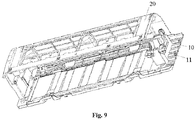
Fig. 9 is a schematic perspective view of the bottom shell and the base inFig. 7 ; -
Fig. 10 shows a partial schematic diagram of the bottom shell matched with the base inFig. 9 ; -
Fig. 11 shows an enlarged view of a local C portion of the bottom shell and the base inFig. 10 ; -
Fig. 12 is a schematic perspective view illustrating a bottom shell, an air-out motor and a drive box cooperating with each other of the air conditioner inFig. 1 ; -
Fig. 13 shows a schematic side view of the fitting of the bottom shell, the air-out motor and the drive box inFig. 12 ; -
Fig. 14 is a partial schematic diagram showing another angle of the cooperation of the bottom shell, the air-out motor and the drive box inFig. 12 . - Reference numerals in the drawings are:
10, bottom shell; 11, boss; 111, snap hole; 112, threaded hole; 113: limiting post; 114,avoidance position; 115, mounting position; 20, panel body; 30, air-out motor; 40. drive box; 41, snap; 42, screw hole; 43, left mounting ear; 44, limited hole; 45, right mounting ear; 46, avoidance structure; 50, side plate; 60, appliance box. - The technical solutions of the present disclosure will be clearly and completely described below with reference to the accompanying drawings, and obviously, the described embodiments are a part of the embodiments of the present disclosure rather than all of the embodiments. Based on the embodiments of the present disclosure, all other embodiments obtained by those skilled in the art without creative efforts fall within the scope of protection of the present disclosure
- The design of a modular air conditioner is a heat tendency developed in the air conditioner industry at present, and the design requirements of the modular air conditioner can facilitate the production assembly of the air conditioner and the post-sale maintenance detection.
- In the modular air conditioner, based on the consideration that the modular air conditioner is easy-to-disassemble and easy-to-cleaning and the electric appliance 's safety aspect during the disassembly process, the present disclosure designs an assembly manner of a drive box, specifically, as shown in
Fig. 1 , the air conditioner of the present embodiment includes abottom shell 10 and adrive box 40, thebottom shell 10 has aboss 11 protruding toward an impeller on which the air conditioner is mounted, and thedrive box 40 is mounted on theboss 11. - By applying the air conditioner of the present embodiment, the
drive box 40 is mounted on theboss 11 of the non-dismantlingmember bottom shell 10, and when the air conditioner is cleaned and dismantled, it is not necessary to dismantle the drive box, and the dismantling workload can be greatly reduced, and meanwhile, an operator's safety in the whole dismantling process is improved. - In the present embodiment, the number of the
drive boxes 40 is two, the number of theprotrusions 11 is also two, the twoprotrusions 11 are respectively formed on two ends of thebottom shell 10 along a longitudinal direction thereof, and each of the twoprotrusions 11 is provided with onedrive box 40. Since the drive box is to drive an air deflector at an air outlet, theboss 11 increases the height, and the drive box can be conveniently installed. The each of the twobosses 11 has three mounting portions, each of the twodrive boxes 40 has three matched mounting portions, and the mounting portions are engaged with or screwed with the matched mounting portions. In an exemplary embodiment, the two mounting portions are engaged with the two mating mounting portions on thedrive box 40, and the other mounting portion in the three mounting portions is screwed with the other matched mounting portion on thedrive box 40. The drive box is fixed on the boss by means of engagement and screw fitting, and the fixing is more reliable and convenient to install. Of course, the drive box may also be fixed to the boss by screwing or engagement connection, and the number of mounting portions is not limited thereto, and needs to be selected according to specific situations. - In the present embodiment, as shown in
Fig. 2 to Fig. 5 , the three mounting portions are twosnap holes 111 and one threadedhole 112 respectively, the three matching mounting portions are twosnaps 41 and one threadedhole 42 respectively, thesnap hole 111 is engaged with thesnap 41, and the threadedhole 112 is threaded with the threadedhole 42. The snap hole and the snap form a snap structure, which is simple in structure and easy to operate. In an exemplary embodiment, the twosnap holes 111 are arranged at intervals along a width direction of thebottom shell 10, and the twosnap holes 111 are formed on an upper part of theboss 11 and cooperated with a bottom part of thedrive box 40. This facilitates the manufacture and reduces the processing difficulty. Of course, the snap may be arranged on the boss, the snap hole may be arranged on the drive box, and the snap is provided with a screw post cooperated with the screw hole. - In the present embodiment, the two
snap holes 111 are respectively formed on a top surface and a side surface of theboss 11, and are adapted to match with thesnap 41 formed by an outwardly protruded convex column on a bottom wall and a side wall when thedrive box 40 is in a mounted state. The protruding column is convenient to manufacture, simple to manufacture and reduces costs. In an exemplary embodiment, onesnap hole 111 is formed on an inner side surface of theboss 11 and is adapted to cooperate with thesnap 41 on the rear side wall when thedrive box 40 is mounted. Wherein, a side where an extension end of a moving piece of the drive box is located is a front side, and the other side, away from the extension end of the moving piece, of the drive box is a rear side, and a wall, facing the bottom shell, of the drive box is a bottom wall. Of course, the two snap holes are also merely formed on the top surface or the side surface of the boss, and at this time, the two convex columns are merely formed on the bottom wall or the side wall when the drive box is in a mounted state. - In the present embodiment, one side wall of the
drive box 40 has a mounting ear protruded outwardly, and thescrew hole 42 is formed on the mounting ear. The arrangement of the mounting ear can simplify the structure of the drive box, and also facilitate the installation of screws. Specifically, the drive box mounted at a left end of thebottom shell 10 is a left drive box, the drive box mounted at a right end of thebottom shell 10 is a right drive box, when the drive box is in a mounted state, a left side wall in the left drive box has an outwardly projecting left mountingear 43, and a right side wall in the right drive box has an outwardly projecting right mountingear 45. - In the present embodiment, the
boss 11 on the left side is provided with a limiting structure, and theleft mounting ear 43 is provided with a limited structure cooperated with the limiting structure. The limiting structure cooperates with the limited structure to serve as a limiting function, and the drive box can be prevented from moving. Of course, the installation position of the limited structure is not limited thereto, and may also be installed at other positions of the drive box. In the embodiment not shown in the figure, a limiting structure may also be arranged on the right boss, and in this case, the right drive box is provided with a limited structure that cooperated with the limiting structure. - As shown in
Figs. 2 and4 , preferably, the limiting structure is a limitingpost 113, the limited structure is alimited hole 44 arranged spaced from thescrew hole 42 and cooperated with the limitingpost 113, and thelimited hole 44 and thescrew hole 42 are arranged along a longitudinal direction of the drive box. The structure of the limiting column and the limited hole is simple and convenient to process. Of course, the limiting structure may also be a limiting hole, and in this case, the limited structure is a limited post. - In the present embodiment, as shown in
Figs. 2 and3 , a side close to an evaporator of the air conditioner, of theboss 11 on the left side is provided with anavoidance position 114 for avoiding the evaporator, and a mountingposition 115 for mounting the air-out motor of the air conditioner is provided on theboss 11 on the right side. In this case, two snap holes in theboss 11 on the left side are respectively located on opposite sides of theavoidance position 114, and two snap holes in theboss 11 on the right side are respectively located on opposite sides of the mountingposition 115. - The assembly structure of the bottom shell and the left drive box is described below with reference to
Figs. 2 and4 , and aboss 11 is provided on a left end of the bottom shell, and a threadedhole 112, a limitingpost 113 and twosnap holes 111 are provided on theboss 11. Ascrew hole 42, alimited hole 44 and twosnaps 41 are disposed on a corresponding left drive box, the twosnap holes 111 on theboss 11 are cooperated with the twosnaps 41 on the left drive box respectively, and the limitingpost 113 on theboss 11 is cooperated with thelimited hole 44 on the left drive box; the threaded hole on theboss 11 is fitted with the screw hole on the left drive box through the screw, and the left drive box can be mounted on the left end of the bottom shell by the above fitting structure. - The assembly structure of the bottom shell and the right drive box is described below with reference to
Figs. 3 ,5 ,10 ,11 and14 , aboss 11 is provided on a right end of the bottom shell, a threadedhole 112 and twosnap holes 111 are provided on theboss 11, ascrew hole 42 and twosnaps 41 are provided on a corresponding right drive box, and onesnap 41 is provided adjacent to thescrew hole 42. twosnap holes 111 on theboss 11 are matched with twosnaps 41 on the right drive box; the threadedhole 112 on theboss 11 and thescrew hole 42 on the right drive box are matched by screws, and the right drive box can be mounted on the right end of the bottom shell by the above fitting structure. - Through the above mounting and fitting structure of the drive box and the bottom shell, the drive box can be mounted and fixed on the bottom shell, when the whole machine needs to be cleaned and dismounted, the drive box is retained on the bottom shell of the dismounting member, the disassembly workload can be greatly reduced without disassembling the charging component drive box, which provides convenience for the cleaning and disassembling of the whole machine.
- In order to facilitate the disassembly and maintenance detection of the drive box, an embodiment of the present disclosure provides a simple manner of the drive box, and specifically, as shown in
Figs. 6 to 9 , the air conditioner of the present embodiment further includes apanel body 20, thepanel body 20 is arranged on thebottom shell 10 and configures a housing having an inner cavity together with thebottom shell 10; thedrive box 40 is arranged in the inner cavity; thedrive box 40 is detachably mounted on thebottom shell 10, and thepanel body 20 is provided with an avoiding structure for avoiding movement of thedetachable drive box 40 there between. - By applying the air conditioner of the present embodiment, the
panel body 20 is provided with an avoiding structure for avoiding a movement of thedisassembly drive box 40 there between, when thedrive box 40 is detected and maintained, aside plate 50 is dismantled firstly and then anappliance box 60 is dismantled, in this case, thedrive box 40 may be exposed to the outside, thedrive box 40 is dismantled from the avoiding structure of thepanel body 20, which greatly facilitates post-sale repair detection of the drive box of the whole machine, however, the panel body does not need to be dismantled, and the workload of post-sale detection and maintenance is reduced.. - In the present embodiment, the positioning structure is formed at an end portion, close to the
drive box 40, of thepanel body 20. In this way, the drive box is conveniently dismantled from a front of the air conditioner, and then detection is performed, which greatly facilitates dismounting and detection of the drive box. In an exemplary embodiment, the avoiding structure is an avoiding gap. The avoiding gap has a simple structure and facilitates processing. - In the present embodiment, as shown in
Fig. 6 , the air conditioner further includes aside plate 50 detachably disposed at one end of thebottom shell 10 and located outside thedrive box 40, theside plate 50 has an auxiliary plate parallel to thepanel body 20 and extending toward thepanel body 20, and the auxiliary plate extends to a position covering thedrive box 40. An extension front end of the auxiliary plate is matched with a side edge of thepanel body 20. - The operation process of detecting and servicing the drive box will be described below. By optimizing the structure of the panel body, the panel body retains an avoiding gap for facilitating the disassembly of the drive box from the front surface, and when detecting and maintaining the drive box, the side plate is firstly dismantled and then the appliance box is dismantled. In this case, the drive box can be completely exposed to the outside (as shown in
Fig. 6 ), and then the drive box is dismantled to perform detection. The above structure does not need to dismantle the panel body when the drive box is maintained, and only the side plate and the appliance box need to be dismantled, which greatly facilitates the dismantling of the drive box, greatly facilitates the post-sale detection of the drive box of the whole machine, and provides great convenience for the detection and maintenance of the drive box of the whole machine. - Based on the consideration that the modular air conditioner is easy to dismantle and easy to maintain, an embodiment of the present disclosure designs a layout form of an air-out motor and an appliance box. Specifically, as shown in
Figs. 12 to 14 , the air conditioner in this embodiment further includes an air-outmotor 30, and the air-outmotor 30 is detachably mounted on thebottom shell 10; thedrive box 40 is mounted on thebottom shell 10, and thedrive box 40 is mounted on thebottom shell 10 with anavoidance structure 46 retained on a path for demounting and moving the air-outmotor 30. - By applying the air conditioner of the present embodiment, the
drive box 40 has anavoidance structure 46 for avoiding a path of detaching and moving the air-outmotor 30, and when the air-outmotor 30 is maintained, the side plate is firstly dismantled and then theappliance box 60 is dismantled, and at this time, the air-outmotor 30 is exposed, and then the air-out motor is dismantled. The drive box has an avoidance structure which does not interfere with the air-out motor, and facilitates the disassembly of the air-out motor, so that facilitates the maintenance and detection of the air-out motor, and reduces the workload of the maintenance personnel. - In the present embodiment, the
avoidance structure 46 extends from the mounting position of the air-outmotor 30 to the side surface of the air conditioner. The above-mentioned structure leaves a channel for facilitating disassembly of the motor from the side surface of the air conditioner, facilitates extracting the air-out motor from the side surface of the air conditioner, and during disassembly, the air-out motor and the drive box do not interfere with each other, thereby facilitating disassembly and detection of the motor. - In the present embodiment, the
drive box 40 is disposed on a side, away from thebottom shell 10, of thewind outlet motor 30, and the side opposites to thebottom shell 10; The bottom, close to thewind outlet motor 30, of thedrive box 40 is provided with an inwardly recessed avoidance groove, so that the avoidance groove forms anavoidance structure 46. That is to say, when the air conditioner is mounted on a wall surface, thedrive box 40 is located in a right front of the air-outmotor 30. Thus, the structure of the avoidance groove is simplified, and the machining is facilitated. Preferably, the groove wall of the avoidance groove is of an arch structure. The arched structure facilitates processing and reduces manufacturing costs. Of course, the shape of the groove wall of the avoidance groove is not limited thereto. - In the present embodiment, as shown in
Fig. 14 , the air-outmotor 30 and thedrive box 40 are both mounted on theboss 11. A high of theboss 11 is increased, and it is convenient to install the drive box and the air-out motor. - In the present embodiment, both sides, located on the avoidance groove, of the
drive box 40 is mounted on theboss 11. In this way, the drive box can be mounted on the boss, and the fixing is more firmly stable. - In the present embodiment, one of the two
bosses 11 is mounted with a air-outmotor 30, and a side, close to thedrive box 40, of theboss 11 is provided with a mountingposition 115 for mounting the air-outmotor 30. The mountingposition 115 facilitates the installation of the air-out motor and simplifies the structure of the drive box. In an exemplary embodiment, the mountingposition 115 is a mounting groove. The mounting groove is adapted to a shape of the air-out motor. - The operation process of detecting and servicing the motor will be described below. The drive box is mounted on a side, close to a front of the air conditioner, of the air-out motor, and a bottom, close to the air-out motor, of the drive box is provided with an arch-shaped avoidance groove, so that the avoidance groove forms a dismantling channel for dismantling the air-out motor from a side of the air conditioner. When the detecting and servicing is performed on the air-out motor, the side plate is firstly removed and then the appliance box is removed, and at this time, an end cover of the motor is exposed, the screw fixing the end cover of the motor is removed, and the end cover of the motor is removed to dismantle the air-out motor. In a process of extracting the motor from the side edge of the air conditioner, the drive box does not interfere with the motor, which greatly facilitates the disassembly and maintenance detection of the motor, and does not need to dismantle the appearance part when the motor is maintained and detected, which is convenient for disassembling the motor and relieves the workload of the person.
- In the description of the present disclosure, it should be noted that the azimuth or positional relationship indicated by the terms "center," "upper," "lower," "left," "right," "vertical," "horizontal," "inner," and "outer" is based on the azimuth or positional relationship shown in the drawings. Rather than indicating or implying that the indicated device or element must have a particular orientation, be constructed and operated in a particular orientation, and therefore is not to be construed as limiting the present disclosure. Furthermore, the terms "first," "second," "third," are used for the purpose of description only and cannot be understood to indicate or imply relative importance.
- Obviously, the above-described embodiments are merely examples made for clarity, and are not limited to the embodiments. Other variations or variations in different forms can also be made by those skilled in the art on the basis of the above description. All embodiments need not be exhaustive here. Apparently obvious variations or variations that are thus introduced are still within the scope of protection created by the present disclosure.
Claims (17)
- An air conditioner comprising:a bottom shell (10);an air-out motor (30) detachably mounted on the bottom shell (10);wherein a drive box (40) is mounted on the bottom shell (10), and the drive box (40) is mounted on the bottom shell (10) with an avoidance structure (46) retained on a path for demounting and moving the air-out motor (30).
- The air conditioner according to claim 1, wherein the avoidance structure (46) extends from a mounting position of the air-out motor (30) to a side surface of the air conditioner.
- The air conditioner according to claim 2, wherein the drive box (40) is arranged on a side, away from the bottom shell (10), of the air-out motor (30), and the side opposites to the bottom shell (10); a bottom, close to the wind outlet motor (30), of the drive box (40) is provided with an avoidance groove recessed inward, and the avoidance groove forms the avoidance structure (46).
- The air conditioner according to claim 3, wherein a groove wall of the avoidance groove is an arch structure.
- The air conditioner according to claim 3, wherein the bottom shell (10) is provided with a boss (11) protruding toward one side of a mounting of the drive box (40), wherein the air-out motor (30) and the drive box (40) are mounted on the boss (11).
- The air conditioner according to claim 5, wherein two sides of the drive box (40) are mounted on the boss (11), and the two sides are located on the avoidance groove.
- The air conditioner according to claim 5, wherein one side, close to the drive box (40), of the boss (11) is provided with a mounting position (115) for mounting the air-out motor (30).
- The air conditioner according to claim 7, wherein the mounting position (115) is a mounting groove.
- The air conditioner according to claim 5, wherein at least one mounting portion is formed on the boss (11), at least one matched mounting portion corresponding to the at least one mounting portion in a one-to-one manner is provided on the drive box (40), and the at least one mounting portion and the at least one matched mounting portion are clamped or screwed.
- The air conditioner according to claim 9, wherein when the at least one mounting portion is in snap fit with the at least one matched mounting portion, each of the at least one mounting portion is a snap hole (111), each of the at least one matched mounting portion is a snap (41) clamped with the snap hole (111), or each of the at least one mounting portion is a snap, and each of the at least one matched mounting portion is a snap hole clamped with the snap.
- The air conditioner according to claim 10, wherein when the each of the at least one mounting portion is the snap hole (111), the number of the snap hole (111) is two, and two snap holes (111) are arranged at intervals along a width direction of the bottom shell (10), the two snap holes (111) are formed at an upper part of the boss (11) and are cooperated with a snap (41) located at a bottom part of the drive box (40).
- The air conditioner according to claim 11, wherein the two snap holes (111) are formed on a top surface and/or a side surface of the boss (11), and are configured to correspondingly engage with the snap (41) formed by a convex column protruded outwardly and disposed on a bottom wall and/or a side wall of the drive box (40) when the drive box is in a mounted state.
- The air conditioner according to claim 12, wherein one snap hole (111) in the two snap holes is formed on an inner side surface of the boss (11) and is adapted to cooperate with the snap (41) on a rear side wall when the drive box (40) is mounted.
- The air conditioner according to claim 9, wherein when the at least one mounting portion is screwed with the at least one matched mounting portion, the each of the at least one mounting portion is a threaded hole (112) or a screw post, and the each of the at least one matched mounting portion is a screw hole (42) screwed with the threaded hole (112) or the screw post.
- The air conditioner according to claim 14, wherein one side wall of the drive box (40) is provided with a mounting ear protruded outwardly, and the screw hole (42) is formed on the mounting ear.
- The air conditioner according to any one of claims 5 to 15, wherein there are two bosses (11), and the two bosses (11) are respectively formed on two ends of the bottom shell (10) along a longitudinal direction thereof, each of the two bosses (11) is provided with one drive box (40), and one of the two bosses (11) is mounted with the air-out motor (30).
- An air conditioner comprising:a bottom shell (10);an air-out motor (30) detachably mounted on the bottom shell (10);wherein the air conditioner further comprises a drive box (40) mounted on the bottom shell (10), wherein when the drive box (40) is mounted on the bottom shell (10), an avoidance structure (46) is provided on a path for demounting and moving the air-out motor (30).
Applications Claiming Priority (2)
| Application Number | Priority Date | Filing Date | Title |
|---|---|---|---|
| CN201710283589.4A CN108800497B (en) | 2017-04-26 | 2017-04-26 | Air conditioner |
| PCT/CN2017/118320 WO2018196418A1 (en) | 2017-04-26 | 2017-12-25 | Air conditioner |
Publications (3)
| Publication Number | Publication Date |
|---|---|
| EP3617610A1 true EP3617610A1 (en) | 2020-03-04 |
| EP3617610A4 EP3617610A4 (en) | 2021-03-17 |
| EP3617610B1 EP3617610B1 (en) | 2023-07-26 |
Family
ID=63919402
Family Applications (1)
| Application Number | Title | Priority Date | Filing Date |
|---|---|---|---|
| EP17906866.3A Active EP3617610B1 (en) | 2017-04-26 | 2017-12-25 | Air conditioner |
Country Status (4)
| Country | Link |
|---|---|
| EP (1) | EP3617610B1 (en) |
| CN (1) | CN108800497B (en) |
| AU (1) | AU2017411717B2 (en) |
| WO (1) | WO2018196418A1 (en) |
Cited By (1)
| Publication number | Priority date | Publication date | Assignee | Title |
|---|---|---|---|---|
| CN113747697A (en) * | 2020-05-28 | 2021-12-03 | 宁波奥克斯电气股份有限公司 | Automatically controlled box mounting structure and air conditioner |
Families Citing this family (4)
| Publication number | Priority date | Publication date | Assignee | Title |
|---|---|---|---|---|
| CN109974348A (en) * | 2019-04-22 | 2019-07-05 | 宁波奥克斯电气股份有限公司 | A kind of evaporator fixed structure and air conditioner |
| CN113125085B (en) * | 2021-03-29 | 2023-10-20 | 西安西电避雷器有限责任公司 | An airtight water tank for non-standard production line testing of high-voltage circuit breaker devices |
| CN113719999B (en) * | 2021-09-03 | 2024-12-31 | 珠海格力电器股份有限公司 | Air guide structure and air conditioner having the same |
| CN222527777U (en) * | 2024-01-11 | 2025-02-25 | 湖北美的楼宇科技有限公司 | Indoor unit and heating and ventilation system |
Family Cites Families (17)
| Publication number | Priority date | Publication date | Assignee | Title |
|---|---|---|---|---|
| JPH0727361A (en) * | 1993-07-13 | 1995-01-27 | Mitsubishi Heavy Ind Ltd | Air conditioner |
| JPH09112944A (en) * | 1995-10-17 | 1997-05-02 | Matsushita Electric Ind Co Ltd | Air conditioner motor mounting device |
| JPH09243160A (en) * | 1996-03-07 | 1997-09-16 | Fujitsu General Ltd | Air conditioner |
| JP2006234280A (en) * | 2005-02-24 | 2006-09-07 | Sharp Corp | Air conditioner |
| KR101482134B1 (en) * | 2009-03-18 | 2015-01-14 | 엘지전자 주식회사 | Air conditioner |
| EP2299191A3 (en) * | 2009-09-10 | 2012-05-02 | LG Electronics Inc. | Indoor unit of air conditioner |
| CN201629619U (en) * | 2010-04-13 | 2010-11-10 | 珠海格力电器股份有限公司 | Motor fixing device and air conditioner with same |
| CN201926086U (en) * | 2010-12-21 | 2011-08-10 | 珠海格力电器股份有限公司 | Suspended ceiling air duct machine and motor fixing structure thereof |
| CN102679453B (en) * | 2012-05-18 | 2016-12-14 | 海尔集团公司 | Air-conditioner |
| CN104422026B (en) * | 2013-09-06 | 2017-06-27 | 广东美的制冷设备有限公司 | Air conditioner room unit |
| CN104422025B (en) * | 2013-09-06 | 2017-03-29 | 广东美的制冷设备有限公司 | Air conditioner room unit |
| CN203671791U (en) * | 2014-01-01 | 2014-06-25 | 广东美的制冷设备有限公司 | Air conditioner outdoor unit |
| CN204026947U (en) * | 2014-07-22 | 2014-12-17 | 美的集团股份有限公司 | The drive unit of air-conditioner and air conditioner room unit |
| CN205402919U (en) * | 2016-02-01 | 2016-07-27 | 珠海格力电器股份有限公司 | Air conditioner indoor unit and air conditioner having same |
| CN105546658A (en) * | 2016-02-01 | 2016-05-04 | 珠海格力电器股份有限公司 | Air conditioner indoor unit and air conditioner with same |
| CN206094493U (en) * | 2016-09-09 | 2017-04-12 | 珠海格力电器股份有限公司 | Shell assembly and air conditioner with same |
| CN106500293A (en) * | 2016-12-16 | 2017-03-15 | 珠海格力电器股份有限公司 | Air conditioner and air deflector driving device thereof |
-
2017
- 2017-04-26 CN CN201710283589.4A patent/CN108800497B/en active Active
- 2017-12-25 AU AU2017411717A patent/AU2017411717B2/en active Active
- 2017-12-25 WO PCT/CN2017/118320 patent/WO2018196418A1/en not_active Ceased
- 2017-12-25 EP EP17906866.3A patent/EP3617610B1/en active Active
Cited By (1)
| Publication number | Priority date | Publication date | Assignee | Title |
|---|---|---|---|---|
| CN113747697A (en) * | 2020-05-28 | 2021-12-03 | 宁波奥克斯电气股份有限公司 | Automatically controlled box mounting structure and air conditioner |
Also Published As
| Publication number | Publication date |
|---|---|
| EP3617610B1 (en) | 2023-07-26 |
| CN108800497A (en) | 2018-11-13 |
| EP3617610A4 (en) | 2021-03-17 |
| WO2018196418A1 (en) | 2018-11-01 |
| CN108800497B (en) | 2021-02-19 |
| AU2017411717B2 (en) | 2021-01-21 |
| AU2017411717A1 (en) | 2019-07-25 |
Similar Documents
| Publication | Publication Date | Title |
|---|---|---|
| EP3617610B1 (en) | Air conditioner | |
| US10739034B2 (en) | Indoor unit for air conditioner | |
| EP3279572B1 (en) | Indoor unit for an air conditioner | |
| CN203375540U (en) | Indoor unit of air conditioner | |
| CN104748344A (en) | Air conditioner indoor unit shell and air conditioner indoor unit provided with same | |
| CN204718072U (en) | The case component of air conditioner room unit and there is its air conditioner room unit | |
| WO2018196771A1 (en) | Air conditioner | |
| WO2019047581A1 (en) | Air conditioner | |
| CN108917151B (en) | Air conditioner | |
| US20250297766A1 (en) | Electric Control Box and Air Conditioner | |
| CN114322096B (en) | Front panel assembly for vertical air conditioner and vertical air conditioner | |
| CN223826365U (en) | Air conditioner outdoor unit and air conditioner with it | |
| CN209801645U (en) | Integrated air conditioner | |
| CN223691283U (en) | Casing assembly and air conditioner | |
| CN109506355B (en) | Evaporator supporting component and vertical air conditioner | |
| CN210463509U (en) | Shell assembly of air conditioner indoor unit and air conditioner indoor unit with shell assembly | |
| CN108401391B (en) | Backboard structure, display device and electronic product | |
| CN222894422U (en) | Volute assembly, fan assembly and heat pump water heater | |
| CN207268497U (en) | Wall-hanging air conditioner indoor unit | |
| CN222263382U (en) | Circuit box assembly | |
| WO2018196770A1 (en) | Air conditioner | |
| CN217388456U (en) | Novel structure of easily maintaining fan motor | |
| CN217357518U (en) | Shell assembly and air conditioner | |
| CN106225056A (en) | Air conditioner room unit and air-conditioner | |
| CN222068839U (en) | Air conditioner |
Legal Events
| Date | Code | Title | Description |
|---|---|---|---|
| STAA | Information on the status of an ep patent application or granted ep patent |
Free format text: STATUS: THE INTERNATIONAL PUBLICATION HAS BEEN MADE |
|
| PUAI | Public reference made under article 153(3) epc to a published international application that has entered the european phase |
Free format text: ORIGINAL CODE: 0009012 |
|
| STAA | Information on the status of an ep patent application or granted ep patent |
Free format text: STATUS: REQUEST FOR EXAMINATION WAS MADE |
|
| 17P | Request for examination filed |
Effective date: 20190710 |
|
| AK | Designated contracting states |
Kind code of ref document: A1 Designated state(s): AL AT BE BG CH CY CZ DE DK EE ES FI FR GB GR HR HU IE IS IT LI LT LU LV MC MK MT NL NO PL PT RO RS SE SI SK SM TR |
|
| AX | Request for extension of the european patent |
Extension state: BA ME |
|
| DAV | Request for validation of the european patent (deleted) | ||
| DAX | Request for extension of the european patent (deleted) | ||
| A4 | Supplementary search report drawn up and despatched |
Effective date: 20210211 |
|
| RIC1 | Information provided on ipc code assigned before grant |
Ipc: F24F 13/10 20060101AFI20210205BHEP Ipc: F24F 13/14 20060101ALI20210205BHEP Ipc: F24F 1/0018 20190101ALI20210205BHEP Ipc: F24F 1/00 20190101ALI20210205BHEP Ipc: F24F 1/0007 20190101ALI20210205BHEP Ipc: F24F 1/0057 20190101ALI20210205BHEP |
|
| GRAP | Despatch of communication of intention to grant a patent |
Free format text: ORIGINAL CODE: EPIDOSNIGR1 |
|
| STAA | Information on the status of an ep patent application or granted ep patent |
Free format text: STATUS: GRANT OF PATENT IS INTENDED |
|
| INTG | Intention to grant announced |
Effective date: 20230424 |
|
| GRAS | Grant fee paid |
Free format text: ORIGINAL CODE: EPIDOSNIGR3 |
|
| GRAA | (expected) grant |
Free format text: ORIGINAL CODE: 0009210 |
|
| STAA | Information on the status of an ep patent application or granted ep patent |
Free format text: STATUS: THE PATENT HAS BEEN GRANTED |
|
| P01 | Opt-out of the competence of the unified patent court (upc) registered |
Effective date: 20230530 |
|
| AK | Designated contracting states |
Kind code of ref document: B1 Designated state(s): AL AT BE BG CH CY CZ DE DK EE ES FI FR GB GR HR HU IE IS IT LI LT LU LV MC MK MT NL NO PL PT RO RS SE SI SK SM TR |
|
| REG | Reference to a national code |
Ref country code: CH Ref legal event code: EP |
|
| REG | Reference to a national code |
Ref country code: IE Ref legal event code: FG4D |
|
| REG | Reference to a national code |
Ref country code: DE Ref legal event code: R096 Ref document number: 602017071975 Country of ref document: DE |
|
| REG | Reference to a national code |
Ref country code: LT Ref legal event code: MG9D |
|
| REG | Reference to a national code |
Ref country code: NL Ref legal event code: MP Effective date: 20230726 |
|
| REG | Reference to a national code |
Ref country code: AT Ref legal event code: MK05 Ref document number: 1592325 Country of ref document: AT Kind code of ref document: T Effective date: 20230726 |
|
| PG25 | Lapsed in a contracting state [announced via postgrant information from national office to epo] |
Ref country code: NL Free format text: LAPSE BECAUSE OF FAILURE TO SUBMIT A TRANSLATION OF THE DESCRIPTION OR TO PAY THE FEE WITHIN THE PRESCRIBED TIME-LIMIT Effective date: 20230726 |
|
| PG25 | Lapsed in a contracting state [announced via postgrant information from national office to epo] |
Ref country code: GR Free format text: LAPSE BECAUSE OF FAILURE TO SUBMIT A TRANSLATION OF THE DESCRIPTION OR TO PAY THE FEE WITHIN THE PRESCRIBED TIME-LIMIT Effective date: 20231027 |
|
| PG25 | Lapsed in a contracting state [announced via postgrant information from national office to epo] |
Ref country code: IS Free format text: LAPSE BECAUSE OF FAILURE TO SUBMIT A TRANSLATION OF THE DESCRIPTION OR TO PAY THE FEE WITHIN THE PRESCRIBED TIME-LIMIT Effective date: 20231126 |
|
| PG25 | Lapsed in a contracting state [announced via postgrant information from national office to epo] |
Ref country code: SE Free format text: LAPSE BECAUSE OF FAILURE TO SUBMIT A TRANSLATION OF THE DESCRIPTION OR TO PAY THE FEE WITHIN THE PRESCRIBED TIME-LIMIT Effective date: 20230726 Ref country code: RS Free format text: LAPSE BECAUSE OF FAILURE TO SUBMIT A TRANSLATION OF THE DESCRIPTION OR TO PAY THE FEE WITHIN THE PRESCRIBED TIME-LIMIT Effective date: 20230726 Ref country code: PT Free format text: LAPSE BECAUSE OF FAILURE TO SUBMIT A TRANSLATION OF THE DESCRIPTION OR TO PAY THE FEE WITHIN THE PRESCRIBED TIME-LIMIT Effective date: 20231127 Ref country code: NO Free format text: LAPSE BECAUSE OF FAILURE TO SUBMIT A TRANSLATION OF THE DESCRIPTION OR TO PAY THE FEE WITHIN THE PRESCRIBED TIME-LIMIT Effective date: 20231026 Ref country code: LV Free format text: LAPSE BECAUSE OF FAILURE TO SUBMIT A TRANSLATION OF THE DESCRIPTION OR TO PAY THE FEE WITHIN THE PRESCRIBED TIME-LIMIT Effective date: 20230726 Ref country code: LT Free format text: LAPSE BECAUSE OF FAILURE TO SUBMIT A TRANSLATION OF THE DESCRIPTION OR TO PAY THE FEE WITHIN THE PRESCRIBED TIME-LIMIT Effective date: 20230726 Ref country code: IS Free format text: LAPSE BECAUSE OF FAILURE TO SUBMIT A TRANSLATION OF THE DESCRIPTION OR TO PAY THE FEE WITHIN THE PRESCRIBED TIME-LIMIT Effective date: 20231126 Ref country code: HR Free format text: LAPSE BECAUSE OF FAILURE TO SUBMIT A TRANSLATION OF THE DESCRIPTION OR TO PAY THE FEE WITHIN THE PRESCRIBED TIME-LIMIT Effective date: 20230726 Ref country code: GR Free format text: LAPSE BECAUSE OF FAILURE TO SUBMIT A TRANSLATION OF THE DESCRIPTION OR TO PAY THE FEE WITHIN THE PRESCRIBED TIME-LIMIT Effective date: 20231027 Ref country code: FI Free format text: LAPSE BECAUSE OF FAILURE TO SUBMIT A TRANSLATION OF THE DESCRIPTION OR TO PAY THE FEE WITHIN THE PRESCRIBED TIME-LIMIT Effective date: 20230726 Ref country code: AT Free format text: LAPSE BECAUSE OF FAILURE TO SUBMIT A TRANSLATION OF THE DESCRIPTION OR TO PAY THE FEE WITHIN THE PRESCRIBED TIME-LIMIT Effective date: 20230726 |
|
| PG25 | Lapsed in a contracting state [announced via postgrant information from national office to epo] |
Ref country code: PL Free format text: LAPSE BECAUSE OF FAILURE TO SUBMIT A TRANSLATION OF THE DESCRIPTION OR TO PAY THE FEE WITHIN THE PRESCRIBED TIME-LIMIT Effective date: 20230726 |
|
| PG25 | Lapsed in a contracting state [announced via postgrant information from national office to epo] |
Ref country code: ES Free format text: LAPSE BECAUSE OF FAILURE TO SUBMIT A TRANSLATION OF THE DESCRIPTION OR TO PAY THE FEE WITHIN THE PRESCRIBED TIME-LIMIT Effective date: 20230726 |
|
| REG | Reference to a national code |
Ref country code: DE Ref legal event code: R097 Ref document number: 602017071975 Country of ref document: DE |
|
| PG25 | Lapsed in a contracting state [announced via postgrant information from national office to epo] |
Ref country code: SM Free format text: LAPSE BECAUSE OF FAILURE TO SUBMIT A TRANSLATION OF THE DESCRIPTION OR TO PAY THE FEE WITHIN THE PRESCRIBED TIME-LIMIT Effective date: 20230726 Ref country code: RO Free format text: LAPSE BECAUSE OF FAILURE TO SUBMIT A TRANSLATION OF THE DESCRIPTION OR TO PAY THE FEE WITHIN THE PRESCRIBED TIME-LIMIT Effective date: 20230726 Ref country code: ES Free format text: LAPSE BECAUSE OF FAILURE TO SUBMIT A TRANSLATION OF THE DESCRIPTION OR TO PAY THE FEE WITHIN THE PRESCRIBED TIME-LIMIT Effective date: 20230726 Ref country code: EE Free format text: LAPSE BECAUSE OF FAILURE TO SUBMIT A TRANSLATION OF THE DESCRIPTION OR TO PAY THE FEE WITHIN THE PRESCRIBED TIME-LIMIT Effective date: 20230726 Ref country code: DK Free format text: LAPSE BECAUSE OF FAILURE TO SUBMIT A TRANSLATION OF THE DESCRIPTION OR TO PAY THE FEE WITHIN THE PRESCRIBED TIME-LIMIT Effective date: 20230726 Ref country code: CZ Free format text: LAPSE BECAUSE OF FAILURE TO SUBMIT A TRANSLATION OF THE DESCRIPTION OR TO PAY THE FEE WITHIN THE PRESCRIBED TIME-LIMIT Effective date: 20230726 Ref country code: SK Free format text: LAPSE BECAUSE OF FAILURE TO SUBMIT A TRANSLATION OF THE DESCRIPTION OR TO PAY THE FEE WITHIN THE PRESCRIBED TIME-LIMIT Effective date: 20230726 |
|
| PG25 | Lapsed in a contracting state [announced via postgrant information from national office to epo] |
Ref country code: IT Free format text: LAPSE BECAUSE OF FAILURE TO SUBMIT A TRANSLATION OF THE DESCRIPTION OR TO PAY THE FEE WITHIN THE PRESCRIBED TIME-LIMIT Effective date: 20230726 |
|
| PLBE | No opposition filed within time limit |
Free format text: ORIGINAL CODE: 0009261 |
|
| STAA | Information on the status of an ep patent application or granted ep patent |
Free format text: STATUS: NO OPPOSITION FILED WITHIN TIME LIMIT |
|
| 26N | No opposition filed |
Effective date: 20240429 |
|
| PG25 | Lapsed in a contracting state [announced via postgrant information from national office to epo] |
Ref country code: SI Free format text: LAPSE BECAUSE OF FAILURE TO SUBMIT A TRANSLATION OF THE DESCRIPTION OR TO PAY THE FEE WITHIN THE PRESCRIBED TIME-LIMIT Effective date: 20230726 |
|
| REG | Reference to a national code |
Ref country code: CH Ref legal event code: PL |
|
| PG25 | Lapsed in a contracting state [announced via postgrant information from national office to epo] |
Ref country code: LU Free format text: LAPSE BECAUSE OF NON-PAYMENT OF DUE FEES Effective date: 20231225 |
|
| PG25 | Lapsed in a contracting state [announced via postgrant information from national office to epo] |
Ref country code: MC Free format text: LAPSE BECAUSE OF FAILURE TO SUBMIT A TRANSLATION OF THE DESCRIPTION OR TO PAY THE FEE WITHIN THE PRESCRIBED TIME-LIMIT Effective date: 20230726 |
|
| GBPC | Gb: european patent ceased through non-payment of renewal fee |
Effective date: 20231225 |
|
| REG | Reference to a national code |
Ref country code: BE Ref legal event code: MM Effective date: 20231231 |
|
| PG25 | Lapsed in a contracting state [announced via postgrant information from national office to epo] |
Ref country code: MC Free format text: LAPSE BECAUSE OF FAILURE TO SUBMIT A TRANSLATION OF THE DESCRIPTION OR TO PAY THE FEE WITHIN THE PRESCRIBED TIME-LIMIT Effective date: 20230726 Ref country code: LU Free format text: LAPSE BECAUSE OF NON-PAYMENT OF DUE FEES Effective date: 20231225 |
|
| REG | Reference to a national code |
Ref country code: IE Ref legal event code: MM4A |
|
| PG25 | Lapsed in a contracting state [announced via postgrant information from national office to epo] |
Ref country code: IE Free format text: LAPSE BECAUSE OF NON-PAYMENT OF DUE FEES Effective date: 20231225 |
|
| PG25 | Lapsed in a contracting state [announced via postgrant information from national office to epo] |
Ref country code: GB Free format text: LAPSE BECAUSE OF NON-PAYMENT OF DUE FEES Effective date: 20231225 |
|
| PG25 | Lapsed in a contracting state [announced via postgrant information from national office to epo] |
Ref country code: BE Free format text: LAPSE BECAUSE OF NON-PAYMENT OF DUE FEES Effective date: 20231231 |
|
| PG25 | Lapsed in a contracting state [announced via postgrant information from national office to epo] |
Ref country code: FR Free format text: LAPSE BECAUSE OF NON-PAYMENT OF DUE FEES Effective date: 20231231 |
|
| PG25 | Lapsed in a contracting state [announced via postgrant information from national office to epo] |
Ref country code: CH Free format text: LAPSE BECAUSE OF NON-PAYMENT OF DUE FEES Effective date: 20231231 |
|
| PG25 | Lapsed in a contracting state [announced via postgrant information from national office to epo] |
Ref country code: IE Free format text: LAPSE BECAUSE OF NON-PAYMENT OF DUE FEES Effective date: 20231225 Ref country code: GB Free format text: LAPSE BECAUSE OF NON-PAYMENT OF DUE FEES Effective date: 20231225 Ref country code: FR Free format text: LAPSE BECAUSE OF NON-PAYMENT OF DUE FEES Effective date: 20231231 Ref country code: CH Free format text: LAPSE BECAUSE OF NON-PAYMENT OF DUE FEES Effective date: 20231231 Ref country code: BE Free format text: LAPSE BECAUSE OF NON-PAYMENT OF DUE FEES Effective date: 20231231 |
|
| PG25 | Lapsed in a contracting state [announced via postgrant information from national office to epo] |
Ref country code: BG Free format text: LAPSE BECAUSE OF FAILURE TO SUBMIT A TRANSLATION OF THE DESCRIPTION OR TO PAY THE FEE WITHIN THE PRESCRIBED TIME-LIMIT Effective date: 20230726 |
|
| PG25 | Lapsed in a contracting state [announced via postgrant information from national office to epo] |
Ref country code: BG Free format text: LAPSE BECAUSE OF FAILURE TO SUBMIT A TRANSLATION OF THE DESCRIPTION OR TO PAY THE FEE WITHIN THE PRESCRIBED TIME-LIMIT Effective date: 20230726 |
|
| PG25 | Lapsed in a contracting state [announced via postgrant information from national office to epo] |
Ref country code: CY Free format text: LAPSE BECAUSE OF FAILURE TO SUBMIT A TRANSLATION OF THE DESCRIPTION OR TO PAY THE FEE WITHIN THE PRESCRIBED TIME-LIMIT; INVALID AB INITIO Effective date: 20171225 |
|
| PG25 | Lapsed in a contracting state [announced via postgrant information from national office to epo] |
Ref country code: HU Free format text: LAPSE BECAUSE OF FAILURE TO SUBMIT A TRANSLATION OF THE DESCRIPTION OR TO PAY THE FEE WITHIN THE PRESCRIBED TIME-LIMIT; INVALID AB INITIO Effective date: 20171225 |
|
| PG25 | Lapsed in a contracting state [announced via postgrant information from national office to epo] |
Ref country code: TR Free format text: LAPSE BECAUSE OF FAILURE TO SUBMIT A TRANSLATION OF THE DESCRIPTION OR TO PAY THE FEE WITHIN THE PRESCRIBED TIME-LIMIT Effective date: 20230726 |
|
| PGFP | Annual fee paid to national office [announced via postgrant information from national office to epo] |
Ref country code: DE Payment date: 20251222 Year of fee payment: 9 |