EP3617570A1 - Gas-permeable unit - Google Patents
Gas-permeable unit Download PDFInfo
- Publication number
- EP3617570A1 EP3617570A1 EP18790376.0A EP18790376A EP3617570A1 EP 3617570 A1 EP3617570 A1 EP 3617570A1 EP 18790376 A EP18790376 A EP 18790376A EP 3617570 A1 EP3617570 A1 EP 3617570A1
- Authority
- EP
- European Patent Office
- Prior art keywords
- housing
- holding member
- ventilation
- explosion
- proof valve
- Prior art date
- Legal status (The legal status is an assumption and is not a legal conclusion. Google has not performed a legal analysis and makes no representation as to the accuracy of the status listed.)
- Granted
Links
- 238000009423 ventilation Methods 0.000 claims abstract description 159
- 239000007788 liquid Substances 0.000 claims description 10
- 230000000149 penetrating effect Effects 0.000 claims description 10
- 239000007787 solid Substances 0.000 claims description 10
- 239000012528 membrane Substances 0.000 abstract description 44
- 239000007789 gas Substances 0.000 description 31
- 238000003780 insertion Methods 0.000 description 21
- 230000037431 insertion Effects 0.000 description 21
- 238000010586 diagram Methods 0.000 description 19
- 238000007689 inspection Methods 0.000 description 18
- 239000000463 material Substances 0.000 description 17
- 229920001971 elastomer Polymers 0.000 description 11
- -1 polybutylene terephthalate Polymers 0.000 description 10
- 238000000034 method Methods 0.000 description 9
- 238000007789 sealing Methods 0.000 description 9
- 230000005856 abnormality Effects 0.000 description 8
- 229920005992 thermoplastic resin Polymers 0.000 description 8
- 229920001187 thermosetting polymer Polymers 0.000 description 8
- 238000003466 welding Methods 0.000 description 7
- 230000000903 blocking effect Effects 0.000 description 6
- 239000000806 elastomer Substances 0.000 description 6
- 239000002184 metal Substances 0.000 description 6
- 238000000465 moulding Methods 0.000 description 5
- 229920000098 polyolefin Polymers 0.000 description 5
- 230000003319 supportive effect Effects 0.000 description 5
- 239000004698 Polyethylene Substances 0.000 description 4
- 239000004734 Polyphenylene sulfide Substances 0.000 description 4
- 239000004743 Polypropylene Substances 0.000 description 4
- 239000007767 bonding agent Substances 0.000 description 4
- 239000002131 composite material Substances 0.000 description 4
- 230000008030 elimination Effects 0.000 description 4
- 238000003379 elimination reaction Methods 0.000 description 4
- 229920002492 poly(sulfone) Polymers 0.000 description 4
- 229920001707 polybutylene terephthalate Polymers 0.000 description 4
- 229920000573 polyethylene Polymers 0.000 description 4
- 229920000139 polyethylene terephthalate Polymers 0.000 description 4
- 239000005020 polyethylene terephthalate Substances 0.000 description 4
- 229920000069 polyphenylene sulfide Polymers 0.000 description 4
- 229920001155 polypropylene Polymers 0.000 description 4
- 230000001012 protector Effects 0.000 description 4
- 229920005989 resin Polymers 0.000 description 4
- 239000011347 resin Substances 0.000 description 4
- 238000005520 cutting process Methods 0.000 description 3
- 230000005489 elastic deformation Effects 0.000 description 3
- 238000005304 joining Methods 0.000 description 3
- 229920001343 polytetrafluoroethylene Polymers 0.000 description 3
- 239000004810 polytetrafluoroethylene Substances 0.000 description 3
- 239000012779 reinforcing material Substances 0.000 description 3
- VXNZUUAINFGPBY-UHFFFAOYSA-N 1-Butene Chemical compound CCC=C VXNZUUAINFGPBY-UHFFFAOYSA-N 0.000 description 2
- 229920000049 Carbon (fiber) Polymers 0.000 description 2
- YCKRFDGAMUMZLT-UHFFFAOYSA-N Fluorine atom Chemical compound [F] YCKRFDGAMUMZLT-UHFFFAOYSA-N 0.000 description 2
- 229920000122 acrylonitrile butadiene styrene Polymers 0.000 description 2
- 239000004917 carbon fiber Substances 0.000 description 2
- 238000000748 compression moulding Methods 0.000 description 2
- 238000004512 die casting Methods 0.000 description 2
- 239000004744 fabric Substances 0.000 description 2
- 229910052731 fluorine Inorganic materials 0.000 description 2
- 239000011737 fluorine Substances 0.000 description 2
- 239000003365 glass fiber Substances 0.000 description 2
- 238000010438 heat treatment Methods 0.000 description 2
- 238000001746 injection moulding Methods 0.000 description 2
- VNWKTOKETHGBQD-UHFFFAOYSA-N methane Chemical compound C VNWKTOKETHGBQD-UHFFFAOYSA-N 0.000 description 2
- 239000000178 monomer Substances 0.000 description 2
- 230000002787 reinforcement Effects 0.000 description 2
- 229920003002 synthetic resin Polymers 0.000 description 2
- 239000000057 synthetic resin Substances 0.000 description 2
- XLYOFNOQVPJJNP-UHFFFAOYSA-N water Substances O XLYOFNOQVPJJNP-UHFFFAOYSA-N 0.000 description 2
- WSSSPWUEQFSQQG-UHFFFAOYSA-N 4-methyl-1-pentene Chemical compound CC(C)CC=C WSSSPWUEQFSQQG-UHFFFAOYSA-N 0.000 description 1
- VGGSQFUCUMXWEO-UHFFFAOYSA-N Ethene Chemical compound C=C VGGSQFUCUMXWEO-UHFFFAOYSA-N 0.000 description 1
- 239000005977 Ethylene Substances 0.000 description 1
- KRHYYFGTRYWZRS-UHFFFAOYSA-M Fluoride anion Chemical compound [F-] KRHYYFGTRYWZRS-UHFFFAOYSA-M 0.000 description 1
- 239000004952 Polyamide Substances 0.000 description 1
- 239000004642 Polyimide Substances 0.000 description 1
- 239000004699 Ultra-high molecular weight polyethylene Substances 0.000 description 1
- 239000004760 aramid Substances 0.000 description 1
- 229920003235 aromatic polyamide Polymers 0.000 description 1
- 229920001577 copolymer Polymers 0.000 description 1
- 239000000428 dust Substances 0.000 description 1
- 230000000694 effects Effects 0.000 description 1
- 229920000840 ethylene tetrafluoroethylene copolymer Polymers 0.000 description 1
- 239000006260 foam Substances 0.000 description 1
- 238000002156 mixing Methods 0.000 description 1
- 230000003534 oscillatory effect Effects 0.000 description 1
- 229920002647 polyamide Polymers 0.000 description 1
- 229920000728 polyester Polymers 0.000 description 1
- 229920001721 polyimide Polymers 0.000 description 1
- 239000011148 porous material Substances 0.000 description 1
- QQONPFPTGQHPMA-UHFFFAOYSA-N propylene Natural products CC=C QQONPFPTGQHPMA-UHFFFAOYSA-N 0.000 description 1
- 125000004805 propylene group Chemical group [H]C([H])([H])C([H])([*:1])C([H])([H])[*:2] 0.000 description 1
- 239000004576 sand Substances 0.000 description 1
- 239000000243 solution Substances 0.000 description 1
- 229920000785 ultra high molecular weight polyethylene Polymers 0.000 description 1
Images


Classifications
-
- F—MECHANICAL ENGINEERING; LIGHTING; HEATING; WEAPONS; BLASTING
- F16—ENGINEERING ELEMENTS AND UNITS; GENERAL MEASURES FOR PRODUCING AND MAINTAINING EFFECTIVE FUNCTIONING OF MACHINES OR INSTALLATIONS; THERMAL INSULATION IN GENERAL
- F16K—VALVES; TAPS; COCKS; ACTUATING-FLOATS; DEVICES FOR VENTING OR AERATING
- F16K17/00—Safety valves; Equalising valves, e.g. pressure relief valves
- F16K17/02—Safety valves; Equalising valves, e.g. pressure relief valves opening on surplus pressure on one side; closing on insufficient pressure on one side
-
- F—MECHANICAL ENGINEERING; LIGHTING; HEATING; WEAPONS; BLASTING
- F16—ENGINEERING ELEMENTS AND UNITS; GENERAL MEASURES FOR PRODUCING AND MAINTAINING EFFECTIVE FUNCTIONING OF MACHINES OR INSTALLATIONS; THERMAL INSULATION IN GENERAL
- F16K—VALVES; TAPS; COCKS; ACTUATING-FLOATS; DEVICES FOR VENTING OR AERATING
- F16K15/00—Check valves
- F16K15/14—Check valves with flexible valve members
- F16K15/148—Check valves with flexible valve members the closure elements being fixed in their centre
-
- F—MECHANICAL ENGINEERING; LIGHTING; HEATING; WEAPONS; BLASTING
- F16—ENGINEERING ELEMENTS AND UNITS; GENERAL MEASURES FOR PRODUCING AND MAINTAINING EFFECTIVE FUNCTIONING OF MACHINES OR INSTALLATIONS; THERMAL INSULATION IN GENERAL
- F16K—VALVES; TAPS; COCKS; ACTUATING-FLOATS; DEVICES FOR VENTING OR AERATING
- F16K27/00—Construction of housing; Use of materials therefor
- F16K27/02—Construction of housing; Use of materials therefor of lift valves
- F16K27/0209—Check valves or pivoted valves
-
- F—MECHANICAL ENGINEERING; LIGHTING; HEATING; WEAPONS; BLASTING
- F16—ENGINEERING ELEMENTS AND UNITS; GENERAL MEASURES FOR PRODUCING AND MAINTAINING EFFECTIVE FUNCTIONING OF MACHINES OR INSTALLATIONS; THERMAL INSULATION IN GENERAL
- F16K—VALVES; TAPS; COCKS; ACTUATING-FLOATS; DEVICES FOR VENTING OR AERATING
- F16K7/00—Diaphragm valves or cut-off apparatus, e.g. with a member deformed, but not moved bodily, to close the passage ; Pinch valves
- F16K7/12—Diaphragm valves or cut-off apparatus, e.g. with a member deformed, but not moved bodily, to close the passage ; Pinch valves with flat, dished, or bowl-shaped diaphragm
- F16K7/14—Diaphragm valves or cut-off apparatus, e.g. with a member deformed, but not moved bodily, to close the passage ; Pinch valves with flat, dished, or bowl-shaped diaphragm arranged to be deformed against a flat seat
- F16K7/17—Diaphragm valves or cut-off apparatus, e.g. with a member deformed, but not moved bodily, to close the passage ; Pinch valves with flat, dished, or bowl-shaped diaphragm arranged to be deformed against a flat seat the diaphragm being actuated by fluid pressure
-
- H—ELECTRICITY
- H01—ELECTRIC ELEMENTS
- H01M—PROCESSES OR MEANS, e.g. BATTERIES, FOR THE DIRECT CONVERSION OF CHEMICAL ENERGY INTO ELECTRICAL ENERGY
- H01M50/00—Constructional details or processes of manufacture of the non-active parts of electrochemical cells other than fuel cells, e.g. hybrid cells
- H01M50/20—Mountings; Secondary casings or frames; Racks, modules or packs; Suspension devices; Shock absorbers; Transport or carrying devices; Holders
- H01M50/249—Mountings; Secondary casings or frames; Racks, modules or packs; Suspension devices; Shock absorbers; Transport or carrying devices; Holders specially adapted for aircraft or vehicles, e.g. cars or trains
-
- H—ELECTRICITY
- H01—ELECTRIC ELEMENTS
- H01M—PROCESSES OR MEANS, e.g. BATTERIES, FOR THE DIRECT CONVERSION OF CHEMICAL ENERGY INTO ELECTRICAL ENERGY
- H01M50/00—Constructional details or processes of manufacture of the non-active parts of electrochemical cells other than fuel cells, e.g. hybrid cells
- H01M50/30—Arrangements for facilitating escape of gases
- H01M50/317—Re-sealable arrangements
- H01M50/325—Re-sealable arrangements comprising deformable valve members, e.g. elastic or flexible valve members
-
- H—ELECTRICITY
- H01—ELECTRIC ELEMENTS
- H01M—PROCESSES OR MEANS, e.g. BATTERIES, FOR THE DIRECT CONVERSION OF CHEMICAL ENERGY INTO ELECTRICAL ENERGY
- H01M2220/00—Batteries for particular applications
- H01M2220/20—Batteries in motive systems, e.g. vehicle, ship, plane
-
- H—ELECTRICITY
- H01—ELECTRIC ELEMENTS
- H01M—PROCESSES OR MEANS, e.g. BATTERIES, FOR THE DIRECT CONVERSION OF CHEMICAL ENERGY INTO ELECTRICAL ENERGY
- H01M50/00—Constructional details or processes of manufacture of the non-active parts of electrochemical cells other than fuel cells, e.g. hybrid cells
- H01M50/20—Mountings; Secondary casings or frames; Racks, modules or packs; Suspension devices; Shock absorbers; Transport or carrying devices; Holders
- H01M50/233—Mountings; Secondary casings or frames; Racks, modules or packs; Suspension devices; Shock absorbers; Transport or carrying devices; Holders characterised by physical properties of casings or racks, e.g. dimensions
- H01M50/24—Mountings; Secondary casings or frames; Racks, modules or packs; Suspension devices; Shock absorbers; Transport or carrying devices; Holders characterised by physical properties of casings or racks, e.g. dimensions adapted for protecting batteries from their environment, e.g. from corrosion
-
- Y—GENERAL TAGGING OF NEW TECHNOLOGICAL DEVELOPMENTS; GENERAL TAGGING OF CROSS-SECTIONAL TECHNOLOGIES SPANNING OVER SEVERAL SECTIONS OF THE IPC; TECHNICAL SUBJECTS COVERED BY FORMER USPC CROSS-REFERENCE ART COLLECTIONS [XRACs] AND DIGESTS
- Y02—TECHNOLOGIES OR APPLICATIONS FOR MITIGATION OR ADAPTATION AGAINST CLIMATE CHANGE
- Y02E—REDUCTION OF GREENHOUSE GAS [GHG] EMISSIONS, RELATED TO ENERGY GENERATION, TRANSMISSION OR DISTRIBUTION
- Y02E60/00—Enabling technologies; Technologies with a potential or indirect contribution to GHG emissions mitigation
- Y02E60/10—Energy storage using batteries
Definitions
- the present invention relates to a ventilation unit.
- an explosion-proof valve described in Patent Document 1 includes: an explosion-proof valve case formed of a synthetic resin, and forming an annular ring shape; an O-ring sealing between the explosion-proof valve case and a pack case; a circular sheet-like ventilation membrane attached to the case so as to close a central opening of the explosion-proof valve case; and a circular plate-like protector formed of a synthetic resin, and overlapped and arranged outside the ventilation membrane. Notches as ventilation holes are provided around the protector, and a small amount of air can go in and out via the ventilation membrane. When an internal pressure rapidly rises at battery abnormality, the protector is folded, and locking by locking projections is released to drop the protector, and therefore, a large passage cross-sectional area is secured instantaneously to release the internal pressure.
- Patent Document 1 Japanese Patent Application Laid-Open Publication No. 2013-168293
- a ventilation member for example, a ventilation membrane
- an explosion-proof valve for eliminating a pressure difference due to pressure increase when abnormality occurs.
- An object of the present invention is to provide a ventilating unit that can realize elimination of a differential pressure in normal time and elimination of a differential pressure when abnormality occurs while enabling to make an inspection before shipment.
- the present invention provides a ventilation unit (1) including: a first ventilation body (10) that permits gas to flow from an inside of a housing (120) to an outside of the housing (120) when internal pressure, which is pressure inside the housing (120), is higher than external pressure, which is pressure outside the housing (120), by a value not less than a predetermined value, and is capable of returning to block flow of the gas from the inside of the housing (120) to the outside of the housing (120); and a second ventilation body (40) that permits gas to flow between the inside of the housing (120) and the outside of the housing (120) even when a pressure difference between the internal pressure and the external pressure is less than the predetermined value.
- a first ventilation body (10) that permits gas to flow from an inside of a housing (120) to an outside of the housing (120) when internal pressure, which is pressure inside the housing (120), is higher than external pressure, which is pressure outside the housing (120), by a value not less than a predetermined value, and is capable of returning to block flow of the gas from the inside
- a support member (30) that supports the first ventilation body (10) and the second ventilation body (40) may be further included.
- a holding member (70) that holds the support member (30) and is attached to the housing (120) may be further included.
- the second ventilation body (40) may prevent a liquid and a solid from penetrating into the inside of the housing (120) from the outside of the housing (120).
- the present invention provides a ventilation unit (1) including: a first ventilation body (10) that closes a first flow path (R1) when a pressure difference between internal pressure, which is pressure inside a housing (120), and external pressure, which is pressure outside the housing (120), is a value less than a predetermined value, and is elastically deformed to open the first flow path (R1) when the internal pressure is higher than the external pressure by a value not less than the predetermined value; and a second ventilation body (40) that is provided to a second flow path (R2) and permits gas to flow between the inside of the housing (120) and the outside of the housing (120) via the second flow path (R2) even when the pressure difference between the internal pressure and the external pressure is less than the predetermined value.
- a first ventilation body (10) that closes a first flow path (R1) when a pressure difference between internal pressure, which is pressure inside a housing (120), and external pressure, which is pressure outside the housing (120), is a value less than a predetermined value, and is elastically deformed to
- a support member (30) that supports the first ventilation body (10) and the second ventilation body (40) may be further included.
- a holding member (70) that holds the support member (30) and is attached to the housing (120) may be further included.
- the support member (30) may be attached to the holding member (70) by being inserted into the holding member (70), the second ventilation body (40) may be fastened to the support member (30), and the first ventilation body (10) is sandwiched between the support member (30) and the holding member (70).
- the holding member (70) may include a butted portion (72), against which a jig (250) used in inserting the support member (30) into the holding member (70) is butted, and a position of the support member (30) with respect to the holding member (70) may be determined by inserting the support member (30) into the holding member (70) until the jig (250) is butted against the butted portion (72).
- the first ventilation body (10) may close the first flow path (R1) by contacting the holding member (70), and may open the first flow path (R1) by separating from the holding member (70).
- a ventilating unit that can realize elimination of a differential pressure in normal time and elimination of a differential pressure when abnormality occurs, while enabling to make an inspection before shipment.
- FIG. 1 is a diagram showing a general configuration of a vehicle 200 loaded with a battery pack 100 to which a ventilation unit 1 related to a first exemplary embodiment is applied.
- FIG. 1 is a diagram viewing the vehicle 200 from the side.
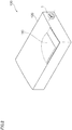
- FIG. 2 is a diagram showing a general configuration of the battery pack 100.
- the vehicle 200 includes: a motor unit 201 provided to a front portion of a vehicle body; and the battery pack 100 provided to a bottom portion of the vehicle body to supply the motor unit 201 with electric power.
- the vehicle 200 is an electric vehicle that drives front wheels with a drive force outputted from the motor unit 201.
- the battery pack 100 includes: a battery 110; a controller (not shown) for controlling the battery 110; various kinds of sensors (not shown) for detecting the state of the battery 110; and a housing 120 that contains the battery 110 or the controller.
- the battery pack 100 also includes a ventilation unit 1 that is attached to the housing 120 to adjust a pressure difference between an internal pressure of the housing 120 and an external pressure of the housing 120.
- the ventilation unit 1 is attached to the housing 120 so that a centerline direction to be described later is horizontal with the ground.
- FIG. 3 is a perspective view showing the ventilation unit 1 related to the first exemplary embodiment.
- FIG. 4 is a perspective view of components constituting the ventilation unit 1 related to the first exemplary embodiment.
- FIG. 5 is a cross-sectional view of the ventilation unit 1 related to the first exemplary embodiment.
- the upper side in each of FIGS. 3 to 5 is referred to as "upward,” and the lower side thereof is referred to as "downward.”
- the ventilation unit 1 includes, as an example of a first ventilation body, an explosion-proof valve 10 that permits gas to flow from the inside of the housing 120 to the outside of the housing 120 when internal pressure, which is the pressure inside the housing 120 is higher than pressure outside the housing 120 (external pressure) by a value not less than a predetermined value, and blocks the flow of the gas from the inside of the housing 120 to the outside of the housing 120 when the internal pressure is not higher than the external pressure by a value not less than the predetermined value.
- internal pressure which is the pressure inside the housing 120 is higher than pressure outside the housing 120 (external pressure) by a value not less than a predetermined value
- the ventilation unit 1 includes an internal pressure adjusting component 20 that permits gas to flow between the inside of the housing 120 and the outside of the housing 120 when the pressure difference between the internal pressure and the external pressure is less than the predetermined value.
- the ventilation unit 1 also includes: a holding member 70 that holds the internal pressure adjusting component 20 and is attached to the housing 120; and a sealing member 80 that is disposed between the holding member 70 and the housing 120 to seal the holding member 70 and the housing 120.
- the internal pressure adjusting component 20 includes a support body 30 as an example of a support member, which is attached to the holding member 70 and on which a communicating hole 33 for communicating the inside of the housing 120 with the outside of the housing 120 is formed.
- the internal pressure adjusting component 20 includes a ventilation membrane 40 as an example of a second ventilation body that is attached to the support body 30 to cover the communicating hole 33 to prevent liquids and solids from penetrating into the inside of the housing 120 from the outside of the housing 120 while permitting flow of gases between the inside of the housing 120 and the outside of the housing 120.
- a ventilation membrane 40 as an example of a second ventilation body that is attached to the support body 30 to cover the communicating hole 33 to prevent liquids and solids from penetrating into the inside of the housing 120 from the outside of the housing 120 while permitting flow of gases between the inside of the housing 120 and the outside of the housing 120.
- the internal pressure adjusting component 20 also includes a cover 50 that protects the ventilation membrane 40 from direct contact with highpressure water and so forth.
- the support body 30 includes a support portion 31 for supporting the ventilation membrane 40 and an insertion portion 32 to be inserted into the holding member 70.
- the communicating hole 33 configured by a through hole that penetrates through the support portion 31 and the insertion portion 32 is formed.
- the support portion 31 is a disk-shaped portion at a center portion of which the communicating hole 33 is formed.
- the outer diameter of the support portion 31 is larger than the outer diameter of the insertion portion 32.
- the support portion 31 includes, around the communicating hole 33, an annular-shaped supportive protruding part 31a that protrudes in a direction different from that of the insertion portion 32.
- the insertion portion 32 has a cylindrical shape having an outer diameter substantially the same as a center portion through hole 71b, which will be described later, formed in the holding member 70.
- the insertion portion 32 includes, at a tip end portion thereof, which is on the side of starting to be inserted into the holding member 70, six leg portions 32a divided along the circumferential direction.
- Each of three leg portions 32a, of the six leg portions 32a, has an outward protruding part 32b that is protruded outwardly in the radial direction from the outer surface.
- the leg portions 32a provided with the outward protruding parts 32b and the leg portions 32a not provided with the outward protruding parts 32b are alternately disposed in the circumferential direction.
- the outward protruding parts 32b of the leg portions 32a are positioned below the center portion through hole 71b formed in the holding member 70 and are butted against a bottom portion 71, which will be described later, of the holding member 70, and thereby the support body 30 is prevented from detaching from the holding member 70.
- thermoplastic resin which is easily molded
- examples of thermoplastic resins except for elastomer can include polybutylene terephthalate (PBT), polyethylene terephthalate (PET), polyphenylene sulfide (PPS), polysulfone (PS), polypropylene (PP), polyethylene (PE), ABS resin or a composite material thereof.
- the examples of the material of the support body 30 can include a composite material made by combining a reinforcement, such as glass fiber or carbon fiber, or metal with the thermoplastic resin to improve heat resistance, humidity resistance, dimensional stability, rigidity or the like.
- the molding method of the support body 30 is not particularly limited; examples thereof can include injection molding, compression molding or cutting.
- the ventilation membrane 40 is formed in a disk shape.
- the outer diameter of the ventilation membrane 40 is larger than the outer diameter of the supportive protruding part 31a of the support portion 31 in the support body 30.
- the ventilation membrane 40 is supported by the supportive protruding part 31a of the support portion 31 to cover the communicating hole 33.
- Examples of the supporting method can include joining by welding the ventilation membrane 40 to the supportive protruding part 31a.
- ventilation membrane 40 and the supportive protruding part 31a may be bonded by a bonding agent or a double-faced tape.
- the ventilation membrane 40 and the support body 30 may be integrated by insert molding.
- the ventilation membrane 40 may be swaged to the support body 30.
- the material, the structure and the form of the ventilation membrane 40 are not particularly limited as long as a sufficient air permeable amount can be secured.
- Examples of the ventilation membrane 40 can include at least a kind selected from a fluorine resin porous body and a polyolefine porous body.
- a fluorine resin polytetrafluoroethylene (PTFE), polychlorotrifluoroethylene, tetrafluoroethylene-hexafluoropropylene copolymer, tetrafluoroethylene-perfluoroalkyl vinyl ether copolymer, tetrafluoroethylene-ethylene copolymer and so forth can be taken as examples.
- polyolefine monomers can include: ethylene; propylene; 4-methylpentene-1; and 1-butene, and polyolefine obtained by homopolymerizing or copolymerizing these monomers can be used.
- the material may be obtained by blending at least two kinds of polyolefine, or may be a layer structure of at least two kinds of polyolefine.
- the ventilation membrane 40 is made of a PTFE porous body that is able to maintain a ventilating property even with a small area and is highly functional to prevent entry of water or dust into the inside of the housing 120.
- a reinforcing material may be laminated to form a layer on at least one surface of the ventilation membrane 40.
- the material, the structure and the form of the reinforcing material are not particularly limited; however, a material having pore diameters larger than those of the ventilation membrane 40 and good ventilating properties, such as a woven cloth, a non-woven cloth, a mesh, a net, a sponge, a foam, a metal porous body or a metal mesh is suitable.
- the reinforcing material made of polyester, polyamide, aramid resin, polyimide, fluoride resin, ultrahigh molecular weight polyethylene, metal or the like is preferred.
- the cover 50 includes a disk-shaped top portion 51 and the extending portions 52 extending from an outermost circumferential part in the top portion 51 toward the support body 30.
- the outer diameter of the top portion 51 is larger than the outer diameter of the ventilation membrane 40, and the top portion 51 covers the ventilation membrane 40 at a position via a predetermined interval from the ventilation membrane 40.
- the extending portions 52 are formed at three locations at regular intervals in the circumferential direction.
- the extending portion 52 includes, at the end portion thereof on the support body 30 side, the inward protruding part 52a that protrudes inwardly.
- the inward protruding parts 52a are fitted into the concave parts 31c formed in the support portion 31 of the support body 30, and thereby the cover 50 is held by the support body 30. Gaps between the extending portions 52 function as a part of the flow path of gases communicating between the inside of the housing 120 and the outside of the housing 120.
- the cover 50 is made of the same material as the support body 30, for example.
- the method of integrating the cover 50 and the support body 30 is not limited to the above-described method that fits the inward protruding parts 52a of the cover 50 into the concave parts 31c formed in the support body 30.
- the cover 50 and the support body 30 may be integrated by thermal welding, ultrasonic welding, oscillatory welding, bonding using a bonding agent, threading or the like.
- the ventilation membrane 40 By covering the ventilation membrane 40 with the cover 50, the ventilation membrane 40 is prevented from being damaged by external forces, or ventilation is prevented from being blocked due to sand, mud and so forth piled on the surface of the ventilation membrane 40.
- the bottom portion 71 includes, at the center portion thereof, a central protruding part 71a that protrudes upwardly in the centerline direction.
- the center portion through hole 71b which is a through hole for holding the internal pressure adjusting component 20, is formed.
- the leg portions 32a of the insertion portion 32 in the support body 30 of the internal pressure adjusting component 20 are inserted into the center portion through hole 71b, and the plural outward protruding parts 32b of the leg portions 32a are spread out of the hole diameter of the center portion through hole 71b below thereof, and accordingly, the internal pressure adjusting component 20 is prevented from detaching from the holding member 70.
- the through holes formed around the central protruding part 71a are referred to as surrounding through holes 71c.
- the side portion 72 is provided cylindrically to cover the ventilation membrane 40 of the internal pressure adjusting component 20 or the outer circumferential portion of the cover 50.
- An upper end surface of the side portion 72 functions as a butted surface (a butted portion) of a jig that inserts the internal pressure adjusting component 20 when the internal pressure adjusting component 20 is attached to the holding member 70. Therefore, the position of the upper end surface of the side portion 72 in the centerline direction is same as the position of the upper end surface of the cover 50 of the internal pressure adjusting component 20.
- the attaching portion 73 includes a cylindrical part 73a in a cylinder shape and protruding parts 73b that protrudes outwardly from an outer circumferential surface of the cylindrical part 73a.
- the protruding parts 73b are formed at four locations at regular intervals in the circumferential direction at the lower end portion of the cylindrical part 73a.
- the cylindrical part 73a is inserted into an insertion hole 121 formed in the housing 120 and then rotated around the centerline at the position where the protruding part 73b enters the housing 120, and thereby the holding member 70 is fitted into the housing 120. Consequently, the ventilation unit 1 is attached to the housing 120.
- the method of attaching the ventilation unit 1 to the housing 120 is not particularly limited.
- the holding member 70 may be press-fitted into the housing 120.
- a male thread is formed, instead of providing the protruding parts 73b, in the cylindrical part 73a of the attaching portion 73, and the ventilation unit 1 may be attached to the housing 120 by screwing the male thread into a female thread formed in the housing 120.
- the material of the holding member 70 is harder than the material of the explosion-proof valve 10.
- a thermoplastic resin which is easily molded, or metal is preferred.
- examples of thermoplastic resins except for elastomer can include polybutylene terephthalate (PBT), polyethylene terephthalate (PET), polyphenylene sulfide (PPS), polysulfone (PS), polypropylene (PP), polyethylene (PE), ABS resin or a composite material thereof.
- the examples of the material of the holding member 70 can include a composite material made by combining a reinforcement, such as glass fiber or carbon fiber, or metal with the thermoplastic resin to improve heat resistance, humidity resistance, dimensional stability, rigidity or the like.
- the molding method of the holding member 70 is not particularly limited; examples thereof can include injection molding, compression molding, die-casting or cutting. Moreover, the support body 30 may be molded by cutting after die-casting.
- the sealing member 80 is an annular-shaped rubber member.
- the inner diameter of the sealing member 80 is not less than the outer diameter of the cylindrical part 73a of the attaching portion 73 in the holding member 70, and the outer diameter of the sealing member 80 is equal to the outer diameter of the bottom portion 71 of the holding member 70. Then, when the holding member 70 is attached to the housing 120, the sealing member 80 is disposed between the holding member 70 and the housing 120 to seal the holding member 70 and the housing 120. In other words, between the holding member 70 and the housing 120, the sealing member 80 prevents liquids and solids from penetrating into the inside of the housing 120 from the outside of the housing 120 while blocking flow of gases between the inside of the housing 120 and the outside of the housing 120.
- the explosion-proof valve 10 includes an annular portion 11 having an annular shape provided to the center, and an inclined portion 12 extending from an outer circumferential part of the annular portion 11 in a direction inclined with respect to the centerline direction and downwardly.
- the inner diameter of the annular portion 11 is not more than the outer diameter of the insertion portion 32 of the support body 30, and the outer diameter of the annular portion 11 is larger than the outer diameter of the support portion 31 of the support body 30 or the outer diameter of the central protruding part 71a of the holding member 70.
- the annular portion 11 is press-fitted into the insertion portion 32 of the support body 30, and thereby the explosion-proof valve 10 is supported by the support body 30.
- the inclined portion 12 extends from the whole circumference of the outer circumferential part of the annular portion 11 obliquely downward, and when viewed in FIG. 5 , the inclined portion 12 includes an upper surface 12a positioned at the upper side, a lower surface 12b positioned at the lower side, and a contact surface 12c that intersects the centerline direction to be brought into contact with the bottom portion 71 of the holding member 70.
- the position where the contact surface 12c contacts a top surface of the bottom portion 71 of the holding member 70 is provided outside of the surrounding through holes 71c formed in the bottom portion 71.
- the radius from the centerline C in the contact surface 12c is larger than a distance from the centerline C to an outermost part of the surrounding through holes 71c.
- the annular portion 11 is sandwiched between the support portion 31 of the support body 30 and the central protruding part 71a of the bottom portion 71 in the holding member 70. Then, in the state where the annular portion 11 is sandwiched between the support portion 31 of the support body 30 and the central protruding part 71a of the holding member 70, the contact surface 12c is brought into contact with the top surface of the bottom portion 71 in the holding member 70. The contact surface 12c is brought into contact with a top surface of the bottom portion 71 of the holding member 70, and thereby a first flow path R1 (refer to FIG. 6 ), through which the gases communicate between the inside of the housing 120 and the outside of the housing 120 via the surrounding through holes 71c formed in the bottom portion 71 of the holding member 70, is closed.
- a first flow path R1 (refer to FIG. 6 ), through which the gases communicate between the inside of the housing 120 and the outside of the housing 120 via the surrounding through holes 71c formed in the bottom portion 71 of the holding member
- the explosion-proof valve 10 is an elastic body, and examples of the material thereof can include a thermosetting elastomer or a thermosetting rubber that is not softened by heating within a certain range and has high heat resistance.
- the annular portion 11 is sandwiched between the support portion 31 of the support body 30 and the central protruding part 71a of the bottom portion 71 in the holding member 70, and thereby the explosion-proof valve 10 seals between the support body 30 and the holding member 70.
- the explosion-proof valve 10 prevents liquids and solids from penetrating into the inside of the housing 120 from the outside of the housing 120 while blocking flow of gases between the inside of the housing 120 and the outside of the housing 120.
- FIG. 6 is a diagram showing a state in which the explosion-proof valve 10 related to the first exemplary embodiment opened the first flow path R1.
- the explosion-proof valve 10 is elastically deformed when the internal pressure, which is the pressure inside the housing 120, is higher than the external pressure, which is the pressure outside the housing 120, by a value not less than a predetermined value, and the contact surface 12c is separated from the bottom portion 71 of the holding member 70, to thereby open the first flow path R1.
- the explosion-proof valve 10 closes the first flow path R1 by bringing the contact surface 12c into contact with the bottom portion 71 of the holding member 70. Then, the shape (the width between the upper surface 12a and the lower surface 12b) or material of the inclined portion 12 is determined so that, when the internal pressure is higher than the external pressure by a value not less than a predetermined value, elastic deformation is caused and the contact surface 12c is separated from the bottom portion 71 of the holding member 70, to thereby open the first flow path R1.
- the explosion-proof valve 10 prevents liquids and solids from penetrating into the inside of the housing 120 from the outside of the housing 120, while blocking flow of gases between the inside of the housing 120 and the outside of the housing 120, via the first flow path R1.
- the ventilation unit 1 when a pressure difference is generated between the pressure inside the housing 120 (internal pressure) and the pressure outside the housing 120 (external pressure), the pressure difference is eliminated by causing gases to communicate between the inside of the housing 120 and the outside of the housing 120 via the ventilation membrane 40.
- the flow paths configured with the communicating hole 33 formed in the support portion 31 of the support body 30 or the gaps between the extending portions 52 function as a second flow path R2 of gases communicating between the inside of the housing 120 and the outside of the housing 120.
- the pressure difference is generated between the internal pressure and the external pressure
- the pressure difference is eliminated by causing the gases to communicate through the second flow path R2 via the ventilation membrane 40.
- the contact surface 12c of the explosion-proof valve 10 is separated from the bottom portion 71 of the holding member 70, and the explosion-proof valve 10 is elastically deformed to open the first flow path R1. Consequently, gases flow from the inside of the housing 120 to the outside of the housing 120 via the first flow path R1, and thereby the pressure difference between the pressure inside the housing 120 (the internal pressure) and the pressure outside the housing 120 (the external pressure) is eliminated.
- the ventilation unit 1 configured as described above is assembled as follows.
- the ventilation membrane 40 is supported (for example, by welding) by the support body 30 of the internal pressure adjusting component 20, and the inward protruding parts 52a of the cover 50 are fitted into the concave parts 31c formed in the support body 30, and thereby the internal pressure adjusting component 20 is assembled.
- the annular portion 11 of the explosion-proof valve 10 is press-fitted into the insertion portion 32 of the support body 30 in the internal pressure adjusting component 20, to thereby integrate the internal pressure adjusting component 20 and the explosion-proof valve 10.
- examples of the integrating method can include joining by welding the explosion-proof valve 10 to the support body 30 of the internal pressure adjusting component 20.
- the explosion-proof valve 10 and the support body 30 of the internal pressure adjusting component 20 may be bonded by a bonding agent or a double-faced tape.
- the explosion-proof valve 10 and the support body 30 of the internal pressure adjusting component 20 may be integrated by insert molding. Then, the internal pressure adjusting component 20 supporting the explosion-proof valve 10 is inserted into the center portion through hole 71b formed in the bottom portion 71 of the holding member 70.
- FIG. 7A is a diagram showing a state before the internal pressure adjusting component 20 is inserted into the holding member 70.
- FIG. 7B is a diagram showing a state after the internal pressure adjusting component 20 is inserted into the holding member 70.
- the internal pressure adjusting component 20 When the internal pressure adjusting component 20 is inserted into the center portion through hole 71b formed in the holding member 70, by a surface larger than the outer diameter of the side portion 72 of the holding member 70, for example, a jig 250 with a lower end surface 251, which is a circle having a diameter larger than the outer diameter of the side portion 72 of the holding member 70, the top portion 51 of the cover 50 in the internal pressure adjusting component 20 is pressurized. Then, as shown in FIG. 7B , the internal pressure adjusting component 20 is pressed into the holding member 70 until the lower end surface 251 of the jig 250 is butted against the side portion 72 of the holding member 70.
- the outward protruding parts 32b of the leg portions 32a in the insertion portion 32 of the support body 30 are positioned below the center portion through hole 71b formed in the bottom portion 71 of the holding member 70. Then, the outward protruding parts 32b of the support body 30 are butted against the bottom portion 71 of the holding member 70, and thereby the internal pressure adjusting component 20 is prevented from detaching from the holding member 70.
- the ventilation unit 1 related to the first exemplary embodiment after the ventilation unit 1 is assembled, it is possible to easily inspect whether or not the explosion-proof valve 10 functions.
- the explosion-proof valve 10 that, when the pressure on the lower surface 12b side of the inclined portion 12 of the explosion-proof valve 10 is increased to be higher than the pressure on the upper surface 12a side of the inclined portion 12 by a value not less than a predetermined value, the contact surface 12c of the explosion-proof valve 10 is separated from the bottom portion 71 of the holding member 70 to open the first flow path R1.
- the explosion-proof valve performs the opening operation with breaking or detaching of a part of components
- the inspection of whether or not the explosion-proof valve functions accompanies actual breaking or detaching; therefore, the inspection cannot be performed easily. For example, it is difficult to deal with those broken by the inspection as products.
- the explosion-proof valve 10 is elastically deformed to separate the contact surface 12c from the bottom portion 71 of the holding member 70, and thereby the first flow path R1 is opened. Therefore, since the contact surface 12c contacts the bottom portion 71 of the holding member 70 to close the first flow path R1 after the inspection is completed, the ventilation unit 1 can be used as a product after inspection.
- FIG. 8 is a diagram showing an example of a state after the function of the explosion-proof valve 10 related to the first exemplary embodiment was inspected.
- the inclined portion 12 is deformed so that the upper surface 12a and the lower surface 12b are reversed with respect to the annular portion 11 as a fulcrum (the upper surface 12a is positioned inside (the centerline C side) and the lower surface 12b is positioned outside).
- the contact surface 12c can be returned again to contact the bottom portion 71 of the holding member 70, to thereby close the first flow path R1, because the material of the explosion-proof valve 10 is the thermosetting elastomer or the thermosetting rubber.
- the ventilation unit 1 related to the first exemplary embodiment it is possible to easily inspect whether or not the explosion-proof valve 10 functions after the ventilation unit 1 has been assembled, as compared to the case where, for example, the explosion-proof valve performs the opening operation with breaking or detaching of a part of components.
- the mode in which the internal pressure adjusting component 20 and the explosion-proof valve 10 are integrated is taken as an example; however, the present invention is not particularly limited to such a mode.
- the internal pressure adjusting component 20 and the explosion-proof valve 10 may be separately assembled to the holding member 70 in a state not to be integrated. Even in such a case, it is desirable that, when the internal pressure adjusting component 20 is attached to the holding member 70, the annular portion 11 of the explosion-proof valve 10 is sandwiched between the internal pressure adjusting component 20 and the holding member 70 in the state of being compressed therebetween to seal between the internal pressure adjusting component 20 and the holding member 70.
- FIG. 9 is a cross-sectional view of a ventilation unit 2 related to a second exemplary embodiment.
- the ventilation unit 2 related to the second exemplary embodiment is different from the ventilation unit 1 related to the first exemplary embodiment in the explosion-proof valve 10 and the holding member 70.
- points different from those of the ventilation unit 1 related to the first exemplary embodiment will be described, but points same as those of the ventilation unit 1 related to the first exemplary embodiment will be assigned with the same signs and detailed description thereof will be omitted.
- the ventilation unit 2 related to the second exemplary embodiment includes an explosion-proof valve 210 and a holding member 270.
- the holding member 270 includes a disk-shaped bottom portion 271, the side portion 72 and the attaching portion 73.
- the bottom portion 271 related to the second exemplary embodiment is different from the bottom portion 71 related to the first exemplary embodiment in the point that the bottom portion 271 is not provided with the central protruding part 71a upwardly protruding at the center portion. Then, in the bottom portion 271 related to the second exemplary embodiment, a center portion through hole 271b, which is a through hole for holding the internal pressure adjusting component 20, is formed.
- leg portions 32a of the insertion portion 32 in the support body 30 of the internal pressure adjusting component 20 are inserted into the center portion through hole 271b, and the plural outward protruding parts 32b of the leg portions 32a are spread out of the hole diameter of the center portion through hole 271b below thereof, and accordingly, the internal pressure adjusting component 20 is prevented from detaching from the holding member 270.
- plural through holes are formed around the center portion through hole 271b.
- the through holes formed around the center portion through hole 271b are referred to as surrounding through holes 271c.
- the explosion-proof valve 210 related to the second exemplary embodiment includes an annular portion 211 having an annular shape provided to the center, and an inclined portion 212 extending from an outer circumferential part of the annular portion 211 in a direction inclined with respect to the centerline direction and upwardly.
- the inner diameter of the annular portion 211 is not more than the outer diameter of the insertion portion 32 of the support body 30, and the outer diameter of the annular portion 211 is set to be positioned inside the surrounding through holes 271c formed in the holding member 270.
- the inclined portion 212 extends from the whole circumference of the outer circumferential part of the annular portion 211 obliquely upward, and when viewed in FIG. 9 , the inclined portion 212 includes an upper surface 212a positioned at the upper side, a lower surface 212b positioned at the lower side, and an intersecting surface 212c that intersects the centerline direction.
- the annular portion 211 is sandwiched between the support portion 31 of the support body 30 and the bottom portion 271 of the holding member 270.
- an intersecting line 212d of the lower surface 212b and the intersecting surface 212c contacts the inner circumferential surface of the side portion 72 of the holding member 270, and thereby the first flow path R1, through which the gases communicate between the inside of the housing 120 and the outside of the housing 120 via the surrounding through holes 271c formed in the bottom portion 271 of the holding member 270, is closed.
- FIG. 10 is a diagram showing a state in which the explosion-proof valve 210 related to the second exemplary embodiment opened the first flow path R1.
- the explosion-proof valve 210 is elastically deformed when the internal pressure, which is the pressure inside the housing 120, is higher than the external pressure, which is the pressure outside the housing 120, by a value not less than a predetermined value, and the intersecting line 212d is separated from the side portion 72 of the holding member 270, to thereby open the first flow path R1.
- the explosion-proof valve 210 closes the first flow path R1 by bringing the intersecting line 212d into contact with the side portion 72 of the holding member 270. Then, the shape (the width between the upper surface 212a and the lower surface 212b) or material of the inclined portion 212 is determined so that, when the internal pressure is higher than the external pressure by a value not less than a predetermined value, elastic deformation is caused and the intersecting line 212d is separated from the side portion 72 of the holding member 270, to thereby open the first flow path R1.
- the explosion-proof valve 210 prevents liquids and solids from penetrating into the inside of the housing 120 from the outside of the housing 120, while blocking flow of gases between the inside of the housing 120 and the outside of the housing 120, via the first flow path R1.
- the ventilation unit 2 related to the second exemplary embodiment configured as described above, when a pressure difference is generated between the pressure inside the housing 120 (internal pressure) and the pressure outside the housing 120 (external pressure), the pressure difference is eliminated by causing gases to communicate between the inside of the housing 120 and the outside of the housing 120 via the ventilation membrane 40.
- the intersecting line 212d of the explosion-proof valve 210 is separated from the side portion 72 of the holding member 270, and the explosion-proof valve 210 is elastically deformed to open the first flow path R1. Consequently, gases flow from the inside of the housing 120 to the outside of the housing 120 via the first flow path R1, and thereby the pressure difference between the pressure inside the housing 120 (the internal pressure) and the pressure outside the housing 120 (the external pressure) is eliminated.
- the ventilation unit 2 related to the second exemplary embodiment configured as described above is assembled as follows.
- the internal pressure adjusting component 20 is assembled as described above, and thereafter, the annular portion 211 of the explosion-proof valve 210 is press-fitted into the insertion portion 32 of the support body 30 in the internal pressure adjusting component 20. Then, the internal pressure adjusting component 20 supporting the explosion-proof valve 210 is inserted into the center portion through hole 271b formed in the bottom portion 271 of the holding member 270.
- the internal pressure adjusting component 20 When the internal pressure adjusting component 20 is inserted into the center portion through hole 271b formed in the holding member 270, the top portion 51 of the cover 50 in the internal pressure adjusting component 20 is pressurized by the jig 250. Then, the internal pressure adjusting component 20 is pressed into the holding member 270 until the lower end surface 251 of the jig 250 is butted against the side portion 72 of the holding member 270. Consequently, the outward protruding parts 32b of the leg portions 32a in the insertion portion 32 of the support body 30 are positioned below the center portion through hole 271b formed in the bottom portion 271 of the holding member 270. Then, the outward protruding parts 32b of the support body 30 are butted against the bottom portion 271 of the holding member 270, and thereby the internal pressure adjusting component 20 is prevented from detaching from the holding member 270.
- the ventilation unit 2 related to the second exemplary embodiment after the ventilation unit 2 is assembled, it is possible to easily inspect whether or not the explosion-proof valve 210 functions.
- the ventilation unit 2 related to the second exemplary embodiment since the intersecting line 212d contacts the side portion 72 of the holding member 270 to close the first flow path R1 after the inspection is completed, the ventilation unit 2 can be used as a product after inspection. Therefore, according to the ventilation unit 2 related to the second exemplary embodiment, it is possible to easily inspect whether or not the explosion-proof valve 210 functions after the ventilation unit 2 has been assembled, as compared to the case where, for example, the explosion-proof valve performs the opening operation with breaking or detaching of a part of components.
- the shape of the inclined portion 212 of the explosion-proof valve 10 is not particularly limited as long as capable of contacting the side portion 72 of the holding member 720.
- the inclined portion 212 may include the upper surface 212a positioned at the upper side, the lower surface 212b positioned at the lower side, and a surface to be brought into surface contact with the inner circumferential surface of the side portion 72 when the inclined portion 212 contacts the side portion 72 of the holding member 270, for instance, a surface in parallel with the centerline direction.
- FIG. 11 is a perspective view of components constituting the ventilation unit 3 related to the third exemplary embodiment.
- FIG. 12 is a cross-sectional view of the ventilation unit 3 related to the third exemplary embodiment.
- the ventilation unit 3 related to the third exemplary embodiment includes an explosion-proof valve 310 that permits gases to flow from the inside of the housing 120 to the outside of the housing 120 when internal pressure, which is the pressure inside the housing 120 is higher than pressure outside the housing 120 (external pressure) by a value not less than a predetermined value, and blocks the flow of the gases from the inside of the housing 120 to the outside of the housing 120 when the internal pressure is not higher than the external pressure by a value not less than the predetermined value.
- the ventilation unit 3 includes the ventilation membrane 40 that prevents liquids and solids from penetrating into the inside of the housing 120 from the outside of the housing 120 while permitting flow of gases between the inside of the housing 120 and the outside of the housing 120.
- the ventilation unit 3 includes a support body 330 that supports the ventilation membrane 40 and the explosion-proof valve 310, while having a communicating hole 340 formed therein to communicate the inside of the housing 120 and the outside of the housing 120 and being inserted into the insertion hole 121 formed in the housing 120.
- the support body 330 is a cylinder-shaped member, and the outer diameter thereof is not more than the hole diameter of the insertion hole 121 formed in the housing 120.
- the support body 330 includes an inward protruding portion 331 that protrudes inwardly from the inner circumferential surface over the whole circumference.
- the support body 330 includes: an upper end outward protruding portion 332 that protrudes outwardly from the outer circumferential surface at the upper end portion; a lower end outward protruding portion 333 that protrudes outwardly from the outer circumferential surface at the lower end portion; and a middle-stage outward protruding portion 334 that protrudes outwardly from the outer circumferential surface between the upper end outward protruding portion 332 and the lower end outward protruding portion 333.
- the ventilation membrane 40 is supported by inward protruding portion 331 of the support body 330 to cover the communicating hole 340.
- the supporting method can include joining by welding the ventilation membrane 40 to the inward protruding portion 331.
- ventilation membrane 40 and the inward protruding portion 331 may be bonded by a bonding agent or a double-faced tape.
- the ventilation membrane 40 and the support body 330 may be integrated by insert molding.
- the ventilation membrane 40 may be swaged to the support body 330.
- the lower end outward protruding portion 333 When the ventilation unit 3 is attached to the housing 120, the lower end outward protruding portion 333 is positioned beneath the insertion hole 121 formed in the housing 120, and the lower end outward protruding portion 333 is butted against the housing 120, to thereby prevent the ventilation unit 3 from detaching from the housing 120.
- the middle-stage outward protruding portion 334 is fitted into a concave part 313a, which will be described later, of the explosion-proof valve 310 to support the explosion-proof valve 310.
- the explosion-proof valve 310 includes an annular portion 311 having an annular shape provided to the center, an inclined portion 312 extending from an outer circumferential part of the annular portion 311 in a direction inclined with respect to the centerline direction and downwardly, and a downward protruding portion 313 protruding downward from an inside end portion in the annular portion 311.
- the concave part 313a having a cylindrical shape and concaved outwardly from the inner circumferential surface is formed.
- the inner diameter of the annular portion 311 and the downward protruding portion 313 is not more than the outer diameter of the support body 330, and the explosion-proof valve 310 is press-fitted over the outer circumferential surface of the support body 330, and thereby supported by the support body 330. Then, the middle-stage outward protruding portion 334 of the support body 330 is fitted into the concave part 313a of the downward protruding portion 313, and thereby the position of the explosion-proof valve 310 in the centerline direction is determined.
- the inclined portion 312 extends from the whole circumference of the outer circumferential part of the annular portion 311 obliquely downward, and when viewed in FIG. 12 , the inclined portion 312 includes an upper surface 312a positioned at the upper side, a lower surface 312b positioned at the lower side, and a contact surface 312c that intersects the centerline direction to be brought into contact with an outer surface of the housing 120.
- the position where the contact surface 312c contacts the outer surface of the housing 120 is provided outside of the surrounding through holes 121c formed around the insertion hole 121 of the housing 120.
- the radius from the centerline C in the contact surface 312c is larger than a distance from the centerline C to an outermost part of the surrounding through holes 121c.
- the annular portion 311 and the downward protruding portion 313 are sandwiched between the upper end outward protruding portion 332 of the support body 330 and the housing 120. Then, in the state where the annular portion 311 and the downward protruding portion 313 are sandwiched between the upper end outward protruding portion 332 of the support body 330 and the housing 120, the contact surface 312c is brought into contact with the outer surface of the housing 120. The contact surface 312c is brought into contact with the outer surface of the housing 120, and thereby the first flow path R1, through which the gases communicate between the inside of the housing 120 and the outside of the housing 120 via the surrounding through holes 121c formed in the housing 120, is closed.
- the explosion-proof valve 310 is an elastic body, and examples of the material thereof can include a thermosetting elastomer or a thermosetting rubber that is not softened by heating within a certain range and has high heat resistance.
- the annular portion 311 and the downward protruding portion 313 are sandwiched between the upper end outward protruding portion 332 of the support body 330 and the housing 120, and thereby the explosion-proof valve 310 seals between the support body 330 and the housing 120.
- the explosion-proof valve 310 prevents liquids and solids from penetrating into the inside of the housing 120 from the outside of the housing 120 while blocking flow of gases between the inside of the housing 120 and the outside of the housing 120.
- FIG. 13 is a diagram showing a state in which the explosion-proof valve 310 related to the third exemplary embodiment opened the first flow path R1.
- the explosion-proof valve 310 is elastically deformed when the internal pressure, which is the pressure inside the housing 120, is higher than the external pressure, which is the pressure outside the housing 120, by a value not less than a predetermined value, and the contact surface 312c is separated from the outer surface of the housing 120, to thereby open the first flow path R1.
- the explosion-proof valve 310 closes the first flow path R1 by bringing the contact surface 312c into contact with the outer surface of the housing 120. Then, the shape (the width between the upper surface 312a and the lower surface 312b) or material of the inclined portion 312 is determined so that, when the internal pressure is higher than the external pressure by a value not less than a predetermined value, elastic deformation is caused and the contact surface 312c is separated from the outer surface of the housing 120, to thereby open the first flow path R1.
- the explosion-proof valve 310 prevents liquids and solids from penetrating into the inside of the housing 120 from the outside of the housing 120, while blocking flow of gases between the inside of the housing 120 and the outside of the housing 120, via the first flow path R1.
- the ventilation unit 3 configured as described above, when a pressure difference is generated between the pressure inside the housing 120 (internal pressure) and the pressure outside the housing 120 (external pressure), the pressure difference is eliminated by causing gases to communicate between the inside of the housing 120 and the outside of the housing 120 via the ventilation membrane 40.
- the flow paths configured with the communicating hole 340 formed in the support body 330 and so forth function as a second flow path R2 of gases communicating between the inside of the housing 120 and the outside of the housing 120.
- the pressure difference is generated between the internal pressure and the external pressure
- the pressure difference is eliminated by causing the gases to communicate through the second flow path R2 via the ventilation membrane 40.
- the contact surface 312c of the explosion-proof valve 310 is separated from the outer surface of the housing 120, and the explosion-proof valve 310 is elastically deformed to open the first flow path R1. Consequently, gases flow from the inside of the housing 120 to the outside of the housing 120 via the first flow path R1, and thereby the pressure difference between the pressure inside the housing 120 (the internal pressure) and the pressure outside the housing 120 (the external pressure) is eliminated.
- the explosion-proof valve 310 is press-fitted over the outer circumferential surface of the support body 330, and thereby the support body 330 and the explosion-proof valve 310 are integrated.
- the middle-stage outward protruding portion 334 of the support body 330 is fitted into the concave part 313a formed in the downward protruding portion 313 of the explosion-proof valve 310, and thereby the position of the explosion-proof valve 310 in the centerline direction is determined.
- the ventilation unit 3 is attached to a plate-like inspection jig in which a through hole, like the insertion hole 121 and the surrounding through holes 121c of the housing 120, is formed.
- the ventilation unit 3 can be used as a product after inspection.
- the ventilation unit 3 related to the third exemplary embodiment it is possible to easily inspect whether or not the explosion-proof valve 310 functions after the ventilation unit 3 has been assembled, as compared to the case where, for example, the explosion-proof valve performs the opening operation with breaking or detaching of a part of components.
- FIG. 14 is a diagram showing an example of a state after the function of the explosion-proof valve 310 related to the third exemplary embodiment was inspected.
- the inclined portion 312 is deformed so that the upper surface 312a and the lower surface 312b are reversed with respect to the annular portion 311 as a fulcrum (the upper surface 312a is positioned inside (the centerline C side) and the lower surface 312b is positioned outside).
- the contact surface 312c can be returned again to contact the surface of the inspection jig, to thereby close the first flow path R1, because the material of the explosion-proof valve 310 is the thermosetting elastomer or the thermosetting rubber.
- the ventilation unit 3 related to the third exemplary embodiment it is possible to easily inspect whether or not the explosion-proof valve 310 functions after the ventilation unit 3 has been assembled, as compared to the case where, for example, the explosion-proof valve performs the opening operation with breaking or detaching of a part of components.
Landscapes
- Engineering & Computer Science (AREA)
- General Engineering & Computer Science (AREA)
- Mechanical Engineering (AREA)
- Chemical & Material Sciences (AREA)
- Chemical Kinetics & Catalysis (AREA)
- Electrochemistry (AREA)
- General Chemical & Material Sciences (AREA)
- Physics & Mathematics (AREA)
- Fluid Mechanics (AREA)
- Aviation & Aerospace Engineering (AREA)
- Gas Exhaust Devices For Batteries (AREA)
- Safety Valves (AREA)
Abstract
Description
- The present invention relates to a ventilation unit.
- Conventionally, a technique that provides a function of a ventilation hole to an explosion-proof valve of a battery pack to eliminate the need to separately provide the ventilation hole including a ventilation membrane has been suggested.
- For example, an explosion-proof valve described in
Patent Document 1 includes: an explosion-proof valve case formed of a synthetic resin, and forming an annular ring shape; an O-ring sealing between the explosion-proof valve case and a pack case; a circular sheet-like ventilation membrane attached to the case so as to close a central opening of the explosion-proof valve case; and a circular plate-like protector formed of a synthetic resin, and overlapped and arranged outside the ventilation membrane. Notches as ventilation holes are provided around the protector, and a small amount of air can go in and out via the ventilation membrane. When an internal pressure rapidly rises at battery abnormality, the protector is folded, and locking by locking projections is released to drop the protector, and therefore, a large passage cross-sectional area is secured instantaneously to release the internal pressure. - Patent Document 1: Japanese Patent Application Laid-Open Publication No.
2013-168293 - For example, in a vehicle-mounted large battery pack, it is desirable to use a ventilation member (for example, a ventilation membrane) for eliminating a pressure difference between the inside and the outside of a housing with temperature changes in normal operation, and to use an explosion-proof valve for eliminating a pressure difference due to pressure increase when abnormality occurs. This is because there is a possibility that the ventilation member eliminating the pressure difference at the normal time cannot sufficiently release the pressure in the housing that is instantaneously increased when abnormality occurs. Considering man-hours for assembling these ventilation member and explosion-proof valve to the housing, it is desirable that the ventilation member and the explosion-proof valve are unitized.
- On the other hand, from the standpoint of ensuring functions of the ventilation member and the explosion-proof valve, it is desirable that normal operations of these components can be inspected before shipment of the products.
- An object of the present invention is to provide a ventilating unit that can realize elimination of a differential pressure in normal time and elimination of a differential pressure when abnormality occurs while enabling to make an inspection before shipment.
- Under such an object, the present invention provides a ventilation unit (1) including: a first ventilation body (10) that permits gas to flow from an inside of a housing (120) to an outside of the housing (120) when internal pressure, which is pressure inside the housing (120), is higher than external pressure, which is pressure outside the housing (120), by a value not less than a predetermined value, and is capable of returning to block flow of the gas from the inside of the housing (120) to the outside of the housing (120); and a second ventilation body (40) that permits gas to flow between the inside of the housing (120) and the outside of the housing (120) even when a pressure difference between the internal pressure and the external pressure is less than the predetermined value.
- Here, a support member (30) that supports the first ventilation body (10) and the second ventilation body (40) may be further included.
- Moreover, a holding member (70) that holds the support member (30) and is attached to the housing (120) may be further included.
- Moreover, the second ventilation body (40) may prevent a liquid and a solid from penetrating into the inside of the housing (120) from the outside of the housing (120).
- Moreover, the present invention provides a ventilation unit (1) including: a first ventilation body (10) that closes a first flow path (R1) when a pressure difference between internal pressure, which is pressure inside a housing (120), and external pressure, which is pressure outside the housing (120), is a value less than a predetermined value, and is elastically deformed to open the first flow path (R1) when the internal pressure is higher than the external pressure by a value not less than the predetermined value; and a second ventilation body (40) that is provided to a second flow path (R2) and permits gas to flow between the inside of the housing (120) and the outside of the housing (120) via the second flow path (R2) even when the pressure difference between the internal pressure and the external pressure is less than the predetermined value.
- Here, a support member (30) that supports the first ventilation body (10) and the second ventilation body (40) may be further included.
- Moreover, a holding member (70) that holds the support member (30) and is attached to the housing (120) may be further included.
- Moreover, the support member (30) may be attached to the holding member (70) by being inserted into the holding member (70), the second ventilation body (40) may be fastened to the support member (30), and the first ventilation body (10) is sandwiched between the support member (30) and the holding member (70).
- Moreover, the holding member (70) may include a butted portion (72), against which a jig (250) used in inserting the support member (30) into the holding member (70) is butted, and a position of the support member (30) with respect to the holding member (70) may be determined by inserting the support member (30) into the holding member (70) until the jig (250) is butted against the butted portion (72).
- Moreover, the first ventilation body (10) may close the first flow path (R1) by contacting the holding member (70), and may open the first flow path (R1) by separating from the holding member (70).
- Note that the above signs in this section are provided for exemplification in describing the present invention, and the present invention is not restricted by these signs.
- According to the present invention, it is possible to provide a ventilating unit that can realize elimination of a differential pressure in normal time and elimination of a differential pressure when abnormality occurs, while enabling to make an inspection before shipment.
-
-
FIG. 1 is a diagram showing a general configuration of a vehicle loaded with a battery pack to which a ventilation unit related to a first exemplary embodiment is applied; -
FIG. 2 is a diagram showing a general configuration of the battery pack; -
FIG. 3 is a perspective view showing the ventilation unit related to the first exemplary embodiment; -
FIG. 4 is a perspective view of components constituting the ventilation unit related to the first exemplary embodiment; -
FIG. 5 is a cross-sectional view of the ventilation unit related to the first exemplary embodiment; -
FIG. 6 is a diagram showing a state in which an explosion-proof valve related to the first exemplary embodiment opened a first flow path; -
FIG. 7A is a diagram showing a state before an internal pressure adjusting component is inserted into a holding member; -
FIG. 7B is a diagram showing a state after the internal pressure adjusting component is inserted into the holding member; -
FIG. 8 is a diagram showing an example of a state after a function of the explosion-proof valve related to the first exemplary embodiment was inspected; -
FIG. 9 is a cross-sectional view of a ventilation unit related to a second exemplary embodiment; -
FIG. 10 is a diagram showing a state in which an explosion-proof valve related to the second exemplary embodiment opened the first flow path; -
FIG. 11 is a perspective view of components constituting a ventilation unit related to a third exemplary embodiment; -
FIG. 12 is a cross-sectional view of the ventilation unit related to the third exemplary embodiment; -
FIG. 13 is a diagram showing a state in which an explosion-proof valve related to the third exemplary embodiment opened the first flow path; and -
FIG. 14 is a diagram showing an example of a state after a function of the explosion-proof valve related to the third exemplary embodiment was inspected. - Hereinafter, exemplary embodiments according to the present invention will be described in detail with reference to attached drawings.
-
FIG. 1 is a diagram showing a general configuration of avehicle 200 loaded with abattery pack 100 to which aventilation unit 1 related to a first exemplary embodiment is applied.FIG. 1 is a diagram viewing thevehicle 200 from the side. -
FIG. 2 is a diagram showing a general configuration of thebattery pack 100. - The
vehicle 200 includes: amotor unit 201 provided to a front portion of a vehicle body; and thebattery pack 100 provided to a bottom portion of the vehicle body to supply themotor unit 201 with electric power. Thevehicle 200 is an electric vehicle that drives front wheels with a drive force outputted from themotor unit 201. - The
battery pack 100 includes: abattery 110; a controller (not shown) for controlling thebattery 110; various kinds of sensors (not shown) for detecting the state of thebattery 110; and ahousing 120 that contains thebattery 110 or the controller. - The
battery pack 100 also includes aventilation unit 1 that is attached to thehousing 120 to adjust a pressure difference between an internal pressure of thehousing 120 and an external pressure of thehousing 120. Theventilation unit 1 is attached to thehousing 120 so that a centerline direction to be described later is horizontal with the ground. -
FIG. 3 is a perspective view showing theventilation unit 1 related to the first exemplary embodiment.FIG. 4 is a perspective view of components constituting theventilation unit 1 related to the first exemplary embodiment.FIG. 5 is a cross-sectional view of theventilation unit 1 related to the first exemplary embodiment. Hereinafter, the upper side in each ofFIGS. 3 to 5 is referred to as "upward," and the lower side thereof is referred to as "downward." - The
ventilation unit 1 includes, as an example of a first ventilation body, an explosion-proof valve 10 that permits gas to flow from the inside of thehousing 120 to the outside of thehousing 120 when internal pressure, which is the pressure inside thehousing 120 is higher than pressure outside the housing 120 (external pressure) by a value not less than a predetermined value, and blocks the flow of the gas from the inside of thehousing 120 to the outside of thehousing 120 when the internal pressure is not higher than the external pressure by a value not less than the predetermined value. - Moreover, the
ventilation unit 1 includes an internalpressure adjusting component 20 that permits gas to flow between the inside of thehousing 120 and the outside of thehousing 120 when the pressure difference between the internal pressure and the external pressure is less than the predetermined value. - The
ventilation unit 1 also includes: a holdingmember 70 that holds the internalpressure adjusting component 20 and is attached to thehousing 120; and a sealingmember 80 that is disposed between the holdingmember 70 and thehousing 120 to seal the holdingmember 70 and thehousing 120. - The internal
pressure adjusting component 20 includes asupport body 30 as an example of a support member, which is attached to the holdingmember 70 and on which a communicatinghole 33 for communicating the inside of thehousing 120 with the outside of thehousing 120 is formed. - Moreover, the internal
pressure adjusting component 20 includes aventilation membrane 40 as an example of a second ventilation body that is attached to thesupport body 30 to cover the communicatinghole 33 to prevent liquids and solids from penetrating into the inside of thehousing 120 from the outside of thehousing 120 while permitting flow of gases between the inside of thehousing 120 and the outside of thehousing 120. - The internal
pressure adjusting component 20 also includes acover 50 that protects theventilation membrane 40 from direct contact with highpressure water and so forth. - The
support body 30 includes asupport portion 31 for supporting theventilation membrane 40 and aninsertion portion 32 to be inserted into the holdingmember 70. At the center portion of thesupport body 30, the communicatinghole 33 configured by a through hole that penetrates through thesupport portion 31 and theinsertion portion 32 is formed. - The
support portion 31 is a disk-shaped portion at a center portion of which the communicatinghole 33 is formed. The outer diameter of thesupport portion 31 is larger than the outer diameter of theinsertion portion 32. Thesupport portion 31 includes, around the communicatinghole 33, an annular-shaped supportive protrudingpart 31a that protrudes in a direction different from that of theinsertion portion 32. - On an outer circumferential portion in the
support portion 31, threelinear parts 31b are provided at regular intervals in the circumferential direction. At a lower end portion of each of thelinear parts 31b, aconcave part 31c that is inwardly concaved is formed. An inward protrudingpart 52a of an extendingportion 52, which will be described later, of thecover 50 is fitted into theconcave part 31c, and thereby thesupport body 30 holds thecover 50. - The
insertion portion 32 has a cylindrical shape having an outer diameter substantially the same as a center portion throughhole 71b, which will be described later, formed in the holdingmember 70. - The
insertion portion 32 includes, at a tip end portion thereof, which is on the side of starting to be inserted into the holdingmember 70, sixleg portions 32a divided along the circumferential direction. Each of threeleg portions 32a, of the sixleg portions 32a, has an outwardprotruding part 32b that is protruded outwardly in the radial direction from the outer surface. Theleg portions 32a provided with the outward protrudingparts 32b and theleg portions 32a not provided with the outward protrudingparts 32b are alternately disposed in the circumferential direction. The outwardprotruding parts 32b of theleg portions 32a are positioned below the center portion throughhole 71b formed in the holdingmember 70 and are butted against abottom portion 71, which will be described later, of the holdingmember 70, and thereby thesupport body 30 is prevented from detaching from the holdingmember 70. - As the material of the
support body 30, though not particularly limited, a thermoplastic resin, which is easily molded, is preferred. As the thermoplastic resin, examples of thermoplastic resins except for elastomer can include polybutylene terephthalate (PBT), polyethylene terephthalate (PET), polyphenylene sulfide (PPS), polysulfone (PS), polypropylene (PP), polyethylene (PE), ABS resin or a composite material thereof. Moreover, the examples of the material of thesupport body 30 can include a composite material made by combining a reinforcement, such as glass fiber or carbon fiber, or metal with the thermoplastic resin to improve heat resistance, humidity resistance, dimensional stability, rigidity or the like. - The molding method of the
support body 30 is not particularly limited; examples thereof can include injection molding, compression molding or cutting. - The
ventilation membrane 40 is formed in a disk shape. The outer diameter of theventilation membrane 40 is larger than the outer diameter of the supportive protrudingpart 31a of thesupport portion 31 in thesupport body 30. Theventilation membrane 40 is supported by the supportive protrudingpart 31a of thesupport portion 31 to cover the communicatinghole 33. Examples of the supporting method can include joining by welding theventilation membrane 40 to the supportive protrudingpart 31a. Other than this,ventilation membrane 40 and the supportive protrudingpart 31a may be bonded by a bonding agent or a double-faced tape. Moreover, theventilation membrane 40 and thesupport body 30 may be integrated by insert molding. Alternatively, theventilation membrane 40 may be swaged to thesupport body 30. - The material, the structure and the form of the
ventilation membrane 40 are not particularly limited as long as a sufficient air permeable amount can be secured. Examples of theventilation membrane 40 can include at least a kind selected from a fluorine resin porous body and a polyolefine porous body. As the fluorine resin, polytetrafluoroethylene (PTFE), polychlorotrifluoroethylene, tetrafluoroethylene-hexafluoropropylene copolymer, tetrafluoroethylene-perfluoroalkyl vinyl ether copolymer, tetrafluoroethylene-ethylene copolymer and so forth can be taken as examples. Examples of polyolefine monomers can include: ethylene; propylene; 4-methylpentene-1; and 1-butene, and polyolefine obtained by homopolymerizing or copolymerizing these monomers can be used. Moreover, the material may be obtained by blending at least two kinds of polyolefine, or may be a layer structure of at least two kinds of polyolefine. Of these, it is particularly preferable that theventilation membrane 40 is made of a PTFE porous body that is able to maintain a ventilating property even with a small area and is highly functional to prevent entry of water or dust into the inside of thehousing 120. - Note that a reinforcing material may be laminated to form a layer on at least one surface of the
ventilation membrane 40. The material, the structure and the form of the reinforcing material are not particularly limited; however, a material having pore diameters larger than those of theventilation membrane 40 and good ventilating properties, such as a woven cloth, a non-woven cloth, a mesh, a net, a sponge, a foam, a metal porous body or a metal mesh is suitable. When heat resistance is required, the reinforcing material made of polyester, polyamide, aramid resin, polyimide, fluoride resin, ultrahigh molecular weight polyethylene, metal or the like is preferred. - The
cover 50 includes a disk-shapedtop portion 51 and the extendingportions 52 extending from an outermost circumferential part in thetop portion 51 toward thesupport body 30. - The outer diameter of the
top portion 51 is larger than the outer diameter of theventilation membrane 40, and thetop portion 51 covers theventilation membrane 40 at a position via a predetermined interval from theventilation membrane 40. - The extending
portions 52 are formed at three locations at regular intervals in the circumferential direction. The extendingportion 52 includes, at the end portion thereof on thesupport body 30 side, the inward protrudingpart 52a that protrudes inwardly. The inwardprotruding parts 52a are fitted into theconcave parts 31c formed in thesupport portion 31 of thesupport body 30, and thereby thecover 50 is held by thesupport body 30. Gaps between the extendingportions 52 function as a part of the flow path of gases communicating between the inside of thehousing 120 and the outside of thehousing 120. - The
cover 50 is made of the same material as thesupport body 30, for example. - Note that the method of integrating the
cover 50 and thesupport body 30 is not limited to the above-described method that fits the inward protrudingparts 52a of thecover 50 into theconcave parts 31c formed in thesupport body 30. For example, thecover 50 and thesupport body 30 may be integrated by thermal welding, ultrasonic welding, oscillatory welding, bonding using a bonding agent, threading or the like. - By covering the
ventilation membrane 40 with thecover 50, theventilation membrane 40 is prevented from being damaged by external forces, or ventilation is prevented from being blocked due to sand, mud and so forth piled on the surface of theventilation membrane 40. - The holding
member 70 includes: a disk-shapedbottom portion 71; aside portion 72 that protrudes upwardly in the centerline direction from the outermost circumferential part in thebottom portion 71 to be provided in the side direction of theventilation membrane 40 of the internalpressure adjusting component 20 or thecover 50; and an attachingportion 73 that protrudes downwardly in the centerline direction from the outer circumferential part in thebottom portion 71 to be attached to thehousing 120. - The
bottom portion 71 includes, at the center portion thereof, a centralprotruding part 71a that protrudes upwardly in the centerline direction. At the center of the central protrudingpart 71a, the center portion throughhole 71b, which is a through hole for holding the internalpressure adjusting component 20, is formed. Theleg portions 32a of theinsertion portion 32 in thesupport body 30 of the internalpressure adjusting component 20 are inserted into the center portion throughhole 71b, and the plural outward protrudingparts 32b of theleg portions 32a are spread out of the hole diameter of the center portion throughhole 71b below thereof, and accordingly, the internalpressure adjusting component 20 is prevented from detaching from the holdingmember 70. - Moreover, in the
bottom portion 71, plural through holes are formed around the central protrudingpart 71a. Hereinafter, the through holes formed around the central protrudingpart 71a are referred to as surrounding throughholes 71c. - The
side portion 72 is provided cylindrically to cover theventilation membrane 40 of the internalpressure adjusting component 20 or the outer circumferential portion of thecover 50. An upper end surface of theside portion 72 functions as a butted surface (a butted portion) of a jig that inserts the internalpressure adjusting component 20 when the internalpressure adjusting component 20 is attached to the holdingmember 70. Therefore, the position of the upper end surface of theside portion 72 in the centerline direction is same as the position of the upper end surface of thecover 50 of the internalpressure adjusting component 20. - The attaching
portion 73 includes acylindrical part 73a in a cylinder shape and protrudingparts 73b that protrudes outwardly from an outer circumferential surface of thecylindrical part 73a. The protrudingparts 73b are formed at four locations at regular intervals in the circumferential direction at the lower end portion of thecylindrical part 73a. - In a state where the protruding
parts 73b of the attachingportion 73 are positioned to facecutouts 121a formed in thehousing 120, thecylindrical part 73a is inserted into aninsertion hole 121 formed in thehousing 120 and then rotated around the centerline at the position where theprotruding part 73b enters thehousing 120, and thereby the holdingmember 70 is fitted into thehousing 120. Consequently, theventilation unit 1 is attached to thehousing 120. - Note that the method of attaching the
ventilation unit 1 to thehousing 120 is not particularly limited. For example, the holdingmember 70 may be press-fitted into thehousing 120. Moreover, for example, a male thread is formed, instead of providing the protrudingparts 73b, in thecylindrical part 73a of the attachingportion 73, and theventilation unit 1 may be attached to thehousing 120 by screwing the male thread into a female thread formed in thehousing 120. - The material of the holding
member 70 is harder than the material of the explosion-proof valve 10. For example, a thermoplastic resin, which is easily molded, or metal is preferred. As the thermoplastic resin, examples of thermoplastic resins except for elastomer can include polybutylene terephthalate (PBT), polyethylene terephthalate (PET), polyphenylene sulfide (PPS), polysulfone (PS), polypropylene (PP), polyethylene (PE), ABS resin or a composite material thereof. Moreover, the examples of the material of the holdingmember 70 can include a composite material made by combining a reinforcement, such as glass fiber or carbon fiber, or metal with the thermoplastic resin to improve heat resistance, humidity resistance, dimensional stability, rigidity or the like. - The molding method of the holding
member 70 is not particularly limited; examples thereof can include injection molding, compression molding, die-casting or cutting. Moreover, thesupport body 30 may be molded by cutting after die-casting. - The sealing
member 80 is an annular-shaped rubber member. The inner diameter of the sealingmember 80 is not less than the outer diameter of thecylindrical part 73a of the attachingportion 73 in the holdingmember 70, and the outer diameter of the sealingmember 80 is equal to the outer diameter of thebottom portion 71 of the holdingmember 70. Then, when the holdingmember 70 is attached to thehousing 120, the sealingmember 80 is disposed between the holdingmember 70 and thehousing 120 to seal the holdingmember 70 and thehousing 120. In other words, between the holdingmember 70 and thehousing 120, the sealingmember 80 prevents liquids and solids from penetrating into the inside of thehousing 120 from the outside of thehousing 120 while blocking flow of gases between the inside of thehousing 120 and the outside of thehousing 120. - The explosion-
proof valve 10 includes anannular portion 11 having an annular shape provided to the center, and aninclined portion 12 extending from an outer circumferential part of theannular portion 11 in a direction inclined with respect to the centerline direction and downwardly. - The inner diameter of the
annular portion 11 is not more than the outer diameter of theinsertion portion 32 of thesupport body 30, and the outer diameter of theannular portion 11 is larger than the outer diameter of thesupport portion 31 of thesupport body 30 or the outer diameter of the central protrudingpart 71a of the holdingmember 70. Theannular portion 11 is press-fitted into theinsertion portion 32 of thesupport body 30, and thereby the explosion-proof valve 10 is supported by thesupport body 30. - The
inclined portion 12 extends from the whole circumference of the outer circumferential part of theannular portion 11 obliquely downward, and when viewed inFIG. 5 , theinclined portion 12 includes anupper surface 12a positioned at the upper side, alower surface 12b positioned at the lower side, and acontact surface 12c that intersects the centerline direction to be brought into contact with thebottom portion 71 of the holdingmember 70. The position where thecontact surface 12c contacts a top surface of thebottom portion 71 of the holdingmember 70 is provided outside of the surrounding throughholes 71c formed in thebottom portion 71. In other words, the radius from the centerline C in thecontact surface 12c is larger than a distance from the centerline C to an outermost part of the surrounding throughholes 71c. - In the explosion-
proof valve 10, theannular portion 11 is sandwiched between thesupport portion 31 of thesupport body 30 and the central protrudingpart 71a of thebottom portion 71 in the holdingmember 70. Then, in the state where theannular portion 11 is sandwiched between thesupport portion 31 of thesupport body 30 and the central protrudingpart 71a of the holdingmember 70, thecontact surface 12c is brought into contact with the top surface of thebottom portion 71 in the holdingmember 70. Thecontact surface 12c is brought into contact with a top surface of thebottom portion 71 of the holdingmember 70, and thereby a first flow path R1 (refer toFIG. 6 ), through which the gases communicate between the inside of thehousing 120 and the outside of thehousing 120 via the surrounding throughholes 71c formed in thebottom portion 71 of the holdingmember 70, is closed. - The explosion-
proof valve 10 is an elastic body, and examples of the material thereof can include a thermosetting elastomer or a thermosetting rubber that is not softened by heating within a certain range and has high heat resistance. - Then, the
annular portion 11 is sandwiched between thesupport portion 31 of thesupport body 30 and the central protrudingpart 71a of thebottom portion 71 in the holdingmember 70, and thereby the explosion-proof valve 10 seals between thesupport body 30 and the holdingmember 70. In other words, between thesupport body 30 and the holdingmember 70, the explosion-proof valve 10 prevents liquids and solids from penetrating into the inside of thehousing 120 from the outside of thehousing 120 while blocking flow of gases between the inside of thehousing 120 and the outside of thehousing 120. -
FIG. 6 is a diagram showing a state in which the explosion-proof valve 10 related to the first exemplary embodiment opened the first flow path R1. - The explosion-
proof valve 10 is elastically deformed when the internal pressure, which is the pressure inside thehousing 120, is higher than the external pressure, which is the pressure outside thehousing 120, by a value not less than a predetermined value, and thecontact surface 12c is separated from thebottom portion 71 of the holdingmember 70, to thereby open the first flow path R1. - To put it another way, when the pressure difference between the internal pressure and the external pressure is less than a predetermined value, the explosion-
proof valve 10 closes the first flow path R1 by bringing thecontact surface 12c into contact with thebottom portion 71 of the holdingmember 70. Then, the shape (the width between theupper surface 12a and thelower surface 12b) or material of theinclined portion 12 is determined so that, when the internal pressure is higher than the external pressure by a value not less than a predetermined value, elastic deformation is caused and thecontact surface 12c is separated from thebottom portion 71 of the holdingmember 70, to thereby open the first flow path R1. - Note that, when the external pressure is higher than the internal pressure, the
contact surface 12c is kept in contact with thebottom portion 71 of the holdingmember 70, and accordingly, the explosion-proof valve 10 continues to close the first flow path R1. Consequently, the explosion-proof valve 10 prevents liquids and solids from penetrating into the inside of thehousing 120 from the outside of thehousing 120, while blocking flow of gases between the inside of thehousing 120 and the outside of thehousing 120, via the first flow path R1. - In the
ventilation unit 1 configured as described above, when a pressure difference is generated between the pressure inside the housing 120 (internal pressure) and the pressure outside the housing 120 (external pressure), the pressure difference is eliminated by causing gases to communicate between the inside of thehousing 120 and the outside of thehousing 120 via theventilation membrane 40. In other words, the flow paths configured with the communicatinghole 33 formed in thesupport portion 31 of thesupport body 30 or the gaps between the extendingportions 52 function as a second flow path R2 of gases communicating between the inside of thehousing 120 and the outside of thehousing 120. When the pressure difference is generated between the internal pressure and the external pressure, the pressure difference is eliminated by causing the gases to communicate through the second flow path R2 via theventilation membrane 40. - If the pressure inside the housing 120 (the internal pressure) is rapidly increased, such as when abnormality occurs in the
battery 110, thecontact surface 12c of the explosion-proof valve 10 is separated from thebottom portion 71 of the holdingmember 70, and the explosion-proof valve 10 is elastically deformed to open the first flow path R1. Consequently, gases flow from the inside of thehousing 120 to the outside of thehousing 120 via the first flow path R1, and thereby the pressure difference between the pressure inside the housing 120 (the internal pressure) and the pressure outside the housing 120 (the external pressure) is eliminated. - The
ventilation unit 1 configured as described above is assembled as follows. - First, the
ventilation membrane 40 is supported (for example, by welding) by thesupport body 30 of the internalpressure adjusting component 20, and the inward protrudingparts 52a of thecover 50 are fitted into theconcave parts 31c formed in thesupport body 30, and thereby the internalpressure adjusting component 20 is assembled. After the internalpressure adjusting component 20 is assembled, theannular portion 11 of the explosion-proof valve 10 is press-fitted into theinsertion portion 32 of thesupport body 30 in the internalpressure adjusting component 20, to thereby integrate the internalpressure adjusting component 20 and the explosion-proof valve 10. Other than this, examples of the integrating method can include joining by welding the explosion-proof valve 10 to thesupport body 30 of the internalpressure adjusting component 20. Moreover, the explosion-proof valve 10 and thesupport body 30 of the internalpressure adjusting component 20 may be bonded by a bonding agent or a double-faced tape. In addition, the explosion-proof valve 10 and thesupport body 30 of the internalpressure adjusting component 20 may be integrated by insert molding. Then, the internalpressure adjusting component 20 supporting the explosion-proof valve 10 is inserted into the center portion throughhole 71b formed in thebottom portion 71 of the holdingmember 70. -
FIG. 7A is a diagram showing a state before the internalpressure adjusting component 20 is inserted into the holdingmember 70.FIG. 7B is a diagram showing a state after the internalpressure adjusting component 20 is inserted into the holdingmember 70. - When the internal
pressure adjusting component 20 is inserted into the center portion throughhole 71b formed in the holdingmember 70, by a surface larger than the outer diameter of theside portion 72 of the holdingmember 70, for example, ajig 250 with alower end surface 251, which is a circle having a diameter larger than the outer diameter of theside portion 72 of the holdingmember 70, thetop portion 51 of thecover 50 in the internalpressure adjusting component 20 is pressurized. Then, as shown inFIG. 7B , the internalpressure adjusting component 20 is pressed into the holdingmember 70 until thelower end surface 251 of thejig 250 is butted against theside portion 72 of the holdingmember 70. Consequently, the outward protrudingparts 32b of theleg portions 32a in theinsertion portion 32 of thesupport body 30 are positioned below the center portion throughhole 71b formed in thebottom portion 71 of the holdingmember 70. Then, the outward protrudingparts 32b of thesupport body 30 are butted against thebottom portion 71 of the holdingmember 70, and thereby the internalpressure adjusting component 20 is prevented from detaching from the holdingmember 70. - In the
ventilation unit 1 related to the first exemplary embodiment, after theventilation unit 1 is assembled, it is possible to easily inspect whether or not the explosion-proof valve 10 functions. In other words, it is possible to inspect the explosion-proof valve 10 that, when the pressure on thelower surface 12b side of theinclined portion 12 of the explosion-proof valve 10 is increased to be higher than the pressure on theupper surface 12a side of theinclined portion 12 by a value not less than a predetermined value, thecontact surface 12c of the explosion-proof valve 10 is separated from thebottom portion 71 of the holdingmember 70 to open the first flow path R1. - For example, if the explosion-proof valve performs the opening operation with breaking or detaching of a part of components, the inspection of whether or not the explosion-proof valve functions accompanies actual breaking or detaching; therefore, the inspection cannot be performed easily. For example, it is difficult to deal with those broken by the inspection as products.
- In contrast thereto, in the
ventilation unit 1 related to the exemplary embodiment, the explosion-proof valve 10 is elastically deformed to separate thecontact surface 12c from thebottom portion 71 of the holdingmember 70, and thereby the first flow path R1 is opened. Therefore, since thecontact surface 12c contacts thebottom portion 71 of the holdingmember 70 to close the first flow path R1 after the inspection is completed, theventilation unit 1 can be used as a product after inspection. -
FIG. 8 is a diagram showing an example of a state after the function of the explosion-proof valve 10 related to the first exemplary embodiment was inspected. In the state shown inFIG. 8 , theinclined portion 12 is deformed so that theupper surface 12a and thelower surface 12b are reversed with respect to theannular portion 11 as a fulcrum (theupper surface 12a is positioned inside (the centerline C side) and thelower surface 12b is positioned outside). - Even though the deformation in the state shown in
FIG. 8 is achieved by increasing the pressure on thelower surface 12b side of theinclined portion 12 of the explosion-proof valve 10 to be higher than the pressure on theupper surface 12a side of theinclined portion 12 by a value not less than a predetermined value, thecontact surface 12c can be returned again to contact thebottom portion 71 of the holdingmember 70, to thereby close the first flow path R1, because the material of the explosion-proof valve 10 is the thermosetting elastomer or the thermosetting rubber. Also, from this, according to theventilation unit 1 related to the first exemplary embodiment, it is possible to easily inspect whether or not the explosion-proof valve 10 functions after theventilation unit 1 has been assembled, as compared to the case where, for example, the explosion-proof valve performs the opening operation with breaking or detaching of a part of components. - Note that, in the above-described first exemplary embodiment, the mode in which the internal
pressure adjusting component 20 and the explosion-proof valve 10 are integrated is taken as an example; however, the present invention is not particularly limited to such a mode. For example, the internalpressure adjusting component 20 and the explosion-proof valve 10 may be separately assembled to the holdingmember 70 in a state not to be integrated. Even in such a case, it is desirable that, when the internalpressure adjusting component 20 is attached to the holdingmember 70, theannular portion 11 of the explosion-proof valve 10 is sandwiched between the internalpressure adjusting component 20 and the holdingmember 70 in the state of being compressed therebetween to seal between the internalpressure adjusting component 20 and the holdingmember 70. -
FIG. 9 is a cross-sectional view of aventilation unit 2 related to a second exemplary embodiment. - The
ventilation unit 2 related to the second exemplary embodiment is different from theventilation unit 1 related to the first exemplary embodiment in the explosion-proof valve 10 and the holdingmember 70. Hereinafter, with respect to theventilation unit 2 related to the second exemplary embodiment, points different from those of theventilation unit 1 related to the first exemplary embodiment will be described, but points same as those of theventilation unit 1 related to the first exemplary embodiment will be assigned with the same signs and detailed description thereof will be omitted. - The
ventilation unit 2 related to the second exemplary embodiment includes an explosion-proof valve 210 and a holdingmember 270. - The holding
member 270 includes a disk-shapedbottom portion 271, theside portion 72 and the attachingportion 73. - The
bottom portion 271 related to the second exemplary embodiment is different from thebottom portion 71 related to the first exemplary embodiment in the point that thebottom portion 271 is not provided with the central protrudingpart 71a upwardly protruding at the center portion. Then, in thebottom portion 271 related to the second exemplary embodiment, a center portion throughhole 271b, which is a through hole for holding the internalpressure adjusting component 20, is formed. Theleg portions 32a of theinsertion portion 32 in thesupport body 30 of the internalpressure adjusting component 20 are inserted into the center portion throughhole 271b, and the plural outward protrudingparts 32b of theleg portions 32a are spread out of the hole diameter of the center portion throughhole 271b below thereof, and accordingly, the internalpressure adjusting component 20 is prevented from detaching from the holdingmember 270. - Moreover, in the
bottom portion 271, plural through holes are formed around the center portion throughhole 271b. Hereinafter, the through holes formed around the center portion throughhole 271b are referred to as surrounding throughholes 271c. - The explosion-
proof valve 210 related to the second exemplary embodiment includes anannular portion 211 having an annular shape provided to the center, and aninclined portion 212 extending from an outer circumferential part of theannular portion 211 in a direction inclined with respect to the centerline direction and upwardly. - The inner diameter of the
annular portion 211 is not more than the outer diameter of theinsertion portion 32 of thesupport body 30, and the outer diameter of theannular portion 211 is set to be positioned inside the surrounding throughholes 271c formed in the holdingmember 270. - The
inclined portion 212 extends from the whole circumference of the outer circumferential part of theannular portion 211 obliquely upward, and when viewed inFIG. 9 , theinclined portion 212 includes anupper surface 212a positioned at the upper side, alower surface 212b positioned at the lower side, and anintersecting surface 212c that intersects the centerline direction. - In the explosion-
proof valve 210, theannular portion 211 is sandwiched between thesupport portion 31 of thesupport body 30 and thebottom portion 271 of the holdingmember 270. In the state where theannular portion 211 is sandwiched between the support portion31 of thesupport body 30 and the holdingmember 270, anintersecting line 212d of thelower surface 212b and the intersectingsurface 212c contacts the inner circumferential surface of theside portion 72 of the holdingmember 270, and thereby the first flow path R1, through which the gases communicate between the inside of thehousing 120 and the outside of thehousing 120 via the surrounding throughholes 271c formed in thebottom portion 271 of the holdingmember 270, is closed. -
FIG. 10 is a diagram showing a state in which the explosion-proof valve 210 related to the second exemplary embodiment opened the first flow path R1. - The explosion-
proof valve 210 is elastically deformed when the internal pressure, which is the pressure inside thehousing 120, is higher than the external pressure, which is the pressure outside thehousing 120, by a value not less than a predetermined value, and theintersecting line 212d is separated from theside portion 72 of the holdingmember 270, to thereby open the first flow path R1. - To put it another way, when the pressure difference between the internal pressure and the external pressure is less than a predetermined value, the explosion-
proof valve 210 closes the first flow path R1 by bringing theintersecting line 212d into contact with theside portion 72 of the holdingmember 270. Then, the shape (the width between theupper surface 212a and thelower surface 212b) or material of theinclined portion 212 is determined so that, when the internal pressure is higher than the external pressure by a value not less than a predetermined value, elastic deformation is caused and theintersecting line 212d is separated from theside portion 72 of the holdingmember 270, to thereby open the first flow path R1. - Note that, when the external pressure is higher than the internal pressure, the
intersecting line 212d is kept in contact with theside portion 72 of the holdingmember 270, and accordingly, the explosion-proof valve 210 continues to close the first flow path R1. Consequently, the explosion-proof valve 210 prevents liquids and solids from penetrating into the inside of thehousing 120 from the outside of thehousing 120, while blocking flow of gases between the inside of thehousing 120 and the outside of thehousing 120, via the first flow path R1. - In the
ventilation unit 2 related to the second exemplary embodiment configured as described above, when a pressure difference is generated between the pressure inside the housing 120 (internal pressure) and the pressure outside the housing 120 (external pressure), the pressure difference is eliminated by causing gases to communicate between the inside of thehousing 120 and the outside of thehousing 120 via theventilation membrane 40. - If the pressure inside the housing 120 (the internal pressure) is rapidly increased, such as when abnormality occurs in the
battery 110, theintersecting line 212d of the explosion-proof valve 210 is separated from theside portion 72 of the holdingmember 270, and the explosion-proof valve 210 is elastically deformed to open the first flow path R1. Consequently, gases flow from the inside of thehousing 120 to the outside of thehousing 120 via the first flow path R1, and thereby the pressure difference between the pressure inside the housing 120 (the internal pressure) and the pressure outside the housing 120 (the external pressure) is eliminated. - The
ventilation unit 2 related to the second exemplary embodiment configured as described above is assembled as follows. - First, the internal
pressure adjusting component 20 is assembled as described above, and thereafter, theannular portion 211 of the explosion-proof valve 210 is press-fitted into theinsertion portion 32 of thesupport body 30 in the internalpressure adjusting component 20. Then, the internalpressure adjusting component 20 supporting the explosion-proof valve 210 is inserted into the center portion throughhole 271b formed in thebottom portion 271 of the holdingmember 270. - When the internal
pressure adjusting component 20 is inserted into the center portion throughhole 271b formed in the holdingmember 270, thetop portion 51 of thecover 50 in the internalpressure adjusting component 20 is pressurized by thejig 250. Then, the internalpressure adjusting component 20 is pressed into the holdingmember 270 until thelower end surface 251 of thejig 250 is butted against theside portion 72 of the holdingmember 270. Consequently, the outward protrudingparts 32b of theleg portions 32a in theinsertion portion 32 of thesupport body 30 are positioned below the center portion throughhole 271b formed in thebottom portion 271 of the holdingmember 270. Then, the outward protrudingparts 32b of thesupport body 30 are butted against thebottom portion 271 of the holdingmember 270, and thereby the internalpressure adjusting component 20 is prevented from detaching from the holdingmember 270. - In the
ventilation unit 2 related to the second exemplary embodiment, after theventilation unit 2 is assembled, it is possible to easily inspect whether or not the explosion-proof valve 210 functions. In other words, it is possible to inspect the explosion-proof valve 210 that, when the pressure on thelower surface 212b side of theinclined portion 212 of the explosion-proof valve 210 is increased to be higher than the pressure on theupper surface 212a side of theinclined portion 212 by a value not less than a predetermined value, theintersecting line 212d of the explosion-proof valve 210 is separated from theside portion 72 of the holdingmember 270 to open the first flow path R1. Then, in theventilation unit 2 related to the second exemplary embodiment, since theintersecting line 212d contacts theside portion 72 of the holdingmember 270 to close the first flow path R1 after the inspection is completed, theventilation unit 2 can be used as a product after inspection. Therefore, according to theventilation unit 2 related to the second exemplary embodiment, it is possible to easily inspect whether or not the explosion-proof valve 210 functions after theventilation unit 2 has been assembled, as compared to the case where, for example, the explosion-proof valve performs the opening operation with breaking or detaching of a part of components. - Note that the shape of the
inclined portion 212 of the explosion-proof valve 10 is not particularly limited as long as capable of contacting theside portion 72 of the holding member 720. For example, theinclined portion 212 may include theupper surface 212a positioned at the upper side, thelower surface 212b positioned at the lower side, and a surface to be brought into surface contact with the inner circumferential surface of theside portion 72 when theinclined portion 212 contacts theside portion 72 of the holdingmember 270, for instance, a surface in parallel with the centerline direction. -
FIG. 11 is a perspective view of components constituting theventilation unit 3 related to the third exemplary embodiment.FIG. 12 is a cross-sectional view of theventilation unit 3 related to the third exemplary embodiment. - Hereinafter, with respect to the
ventilation unit 3 related to the third exemplary embodiment, points different from those of theventilation unit 1 related to the first exemplary embodiment will be described, but points same as those of theventilation unit 1 related to the first exemplary embodiment will be assigned with the same signs and detailed description thereof will be omitted. - The
ventilation unit 3 related to the third exemplary embodiment includes an explosion-proof valve 310 that permits gases to flow from the inside of thehousing 120 to the outside of thehousing 120 when internal pressure, which is the pressure inside thehousing 120 is higher than pressure outside the housing 120 (external pressure) by a value not less than a predetermined value, and blocks the flow of the gases from the inside of thehousing 120 to the outside of thehousing 120 when the internal pressure is not higher than the external pressure by a value not less than the predetermined value. - Moreover, the
ventilation unit 3 includes theventilation membrane 40 that prevents liquids and solids from penetrating into the inside of thehousing 120 from the outside of thehousing 120 while permitting flow of gases between the inside of thehousing 120 and the outside of thehousing 120. - Moreover, the
ventilation unit 3 includes asupport body 330 that supports theventilation membrane 40 and the explosion-proof valve 310, while having a communicatinghole 340 formed therein to communicate the inside of thehousing 120 and the outside of thehousing 120 and being inserted into theinsertion hole 121 formed in thehousing 120. - The
support body 330 is a cylinder-shaped member, and the outer diameter thereof is not more than the hole diameter of theinsertion hole 121 formed in thehousing 120. Thesupport body 330 includes an inward protrudingportion 331 that protrudes inwardly from the inner circumferential surface over the whole circumference. Moreover, thesupport body 330 includes: an upper end outward protrudingportion 332 that protrudes outwardly from the outer circumferential surface at the upper end portion; a lower end outward protrudingportion 333 that protrudes outwardly from the outer circumferential surface at the lower end portion; and a middle-stage outward protrudingportion 334 that protrudes outwardly from the outer circumferential surface between the upper end outward protrudingportion 332 and the lower end outward protrudingportion 333. - The
ventilation membrane 40 is supported by inward protrudingportion 331 of thesupport body 330 to cover the communicatinghole 340. Examples of the supporting method can include joining by welding theventilation membrane 40 to the inward protrudingportion 331. Other than this,ventilation membrane 40 and the inward protrudingportion 331 may be bonded by a bonding agent or a double-faced tape. Moreover, theventilation membrane 40 and thesupport body 330 may be integrated by insert molding. Alternatively, theventilation membrane 40 may be swaged to thesupport body 330. - When the
ventilation unit 3 is attached to thehousing 120, the lower end outward protrudingportion 333 is positioned beneath theinsertion hole 121 formed in thehousing 120, and the lower end outward protrudingportion 333 is butted against thehousing 120, to thereby prevent theventilation unit 3 from detaching from thehousing 120. - The middle-stage outward protruding
portion 334 is fitted into aconcave part 313a, which will be described later, of the explosion-proof valve 310 to support the explosion-proof valve 310. - The explosion-
proof valve 310 includes anannular portion 311 having an annular shape provided to the center, aninclined portion 312 extending from an outer circumferential part of theannular portion 311 in a direction inclined with respect to the centerline direction and downwardly, and a downward protrudingportion 313 protruding downward from an inside end portion in theannular portion 311. - In the downward protruding
portion 313, theconcave part 313a having a cylindrical shape and concaved outwardly from the inner circumferential surface is formed. - The inner diameter of the
annular portion 311 and the downward protrudingportion 313 is not more than the outer diameter of thesupport body 330, and the explosion-proof valve 310 is press-fitted over the outer circumferential surface of thesupport body 330, and thereby supported by thesupport body 330. Then, the middle-stage outward protrudingportion 334 of thesupport body 330 is fitted into theconcave part 313a of the downward protrudingportion 313, and thereby the position of the explosion-proof valve 310 in the centerline direction is determined. - The
inclined portion 312 extends from the whole circumference of the outer circumferential part of theannular portion 311 obliquely downward, and when viewed inFIG. 12 , theinclined portion 312 includes anupper surface 312a positioned at the upper side, alower surface 312b positioned at the lower side, and acontact surface 312c that intersects the centerline direction to be brought into contact with an outer surface of thehousing 120. The position where thecontact surface 312c contacts the outer surface of thehousing 120 is provided outside of the surrounding throughholes 121c formed around theinsertion hole 121 of thehousing 120. In other words, when theventilation unit 3 is attached to thehousing 120, the radius from the centerline C in thecontact surface 312c is larger than a distance from the centerline C to an outermost part of the surrounding throughholes 121c. - In the explosion-
proof valve 310, theannular portion 311 and the downward protrudingportion 313 are sandwiched between the upper end outward protrudingportion 332 of thesupport body 330 and thehousing 120. Then, in the state where theannular portion 311 and the downward protrudingportion 313 are sandwiched between the upper end outward protrudingportion 332 of thesupport body 330 and thehousing 120, thecontact surface 312c is brought into contact with the outer surface of thehousing 120. Thecontact surface 312c is brought into contact with the outer surface of thehousing 120, and thereby the first flow path R1, through which the gases communicate between the inside of thehousing 120 and the outside of thehousing 120 via the surrounding throughholes 121c formed in thehousing 120, is closed. - The explosion-
proof valve 310 is an elastic body, and examples of the material thereof can include a thermosetting elastomer or a thermosetting rubber that is not softened by heating within a certain range and has high heat resistance. - Then, the
annular portion 311 and the downward protrudingportion 313 are sandwiched between the upper end outward protrudingportion 332 of thesupport body 330 and thehousing 120, and thereby the explosion-proof valve 310 seals between thesupport body 330 and thehousing 120. In other words, between the outer surface of thesupport body 330 and thehousing 120, the explosion-proof valve 310 prevents liquids and solids from penetrating into the inside of thehousing 120 from the outside of thehousing 120 while blocking flow of gases between the inside of thehousing 120 and the outside of thehousing 120. -
FIG. 13 is a diagram showing a state in which the explosion-proof valve 310 related to the third exemplary embodiment opened the first flow path R1. - The explosion-
proof valve 310 is elastically deformed when the internal pressure, which is the pressure inside thehousing 120, is higher than the external pressure, which is the pressure outside thehousing 120, by a value not less than a predetermined value, and thecontact surface 312c is separated from the outer surface of thehousing 120, to thereby open the first flow path R1. - To put it another way, when the pressure difference between the internal pressure and the external pressure is less than a predetermined value, the explosion-
proof valve 310 closes the first flow path R1 by bringing thecontact surface 312c into contact with the outer surface of thehousing 120. Then, the shape (the width between theupper surface 312a and thelower surface 312b) or material of theinclined portion 312 is determined so that, when the internal pressure is higher than the external pressure by a value not less than a predetermined value, elastic deformation is caused and thecontact surface 312c is separated from the outer surface of thehousing 120, to thereby open the first flow path R1. - Note that, when the external pressure is higher than the internal pressure, the
contact surface 312c is kept in contact with the outer surface of thehousing 120, and accordingly, the explosion-proof valve 310 continues to close the first flow path R1. Consequently, the explosion-proof valve 310 prevents liquids and solids from penetrating into the inside of thehousing 120 from the outside of thehousing 120, while blocking flow of gases between the inside of thehousing 120 and the outside of thehousing 120, via the first flow path R1. - In the
ventilation unit 3 configured as described above, when a pressure difference is generated between the pressure inside the housing 120 (internal pressure) and the pressure outside the housing 120 (external pressure), the pressure difference is eliminated by causing gases to communicate between the inside of thehousing 120 and the outside of thehousing 120 via theventilation membrane 40. In other words, the flow paths configured with the communicatinghole 340 formed in thesupport body 330 and so forth function as a second flow path R2 of gases communicating between the inside of thehousing 120 and the outside of thehousing 120. When the pressure difference is generated between the internal pressure and the external pressure, the pressure difference is eliminated by causing the gases to communicate through the second flow path R2 via theventilation membrane 40. - If the pressure inside the housing 120 (the internal pressure) is rapidly increased, such as when abnormality occurs in the
battery 110, thecontact surface 312c of the explosion-proof valve 310 is separated from the outer surface of thehousing 120, and the explosion-proof valve 310 is elastically deformed to open the first flow path R1. Consequently, gases flow from the inside of thehousing 120 to the outside of thehousing 120 via the first flow path R1, and thereby the pressure difference between the pressure inside the housing 120 (the internal pressure) and the pressure outside the housing 120 (the external pressure) is eliminated. - In the
ventilation unit 3 configured as described above, the explosion-proof valve 310 is press-fitted over the outer circumferential surface of thesupport body 330, and thereby thesupport body 330 and the explosion-proof valve 310 are integrated. The middle-stage outward protrudingportion 334 of thesupport body 330 is fitted into theconcave part 313a formed in the downward protrudingportion 313 of the explosion-proof valve 310, and thereby the position of the explosion-proof valve 310 in the centerline direction is determined. - In the
ventilation unit 3 related to the third exemplary embodiment, after theventilation unit 3 is assembled, it is possible to easily inspect whether or not the explosion-proof valve 310 functions. Theventilation unit 3 is attached to a plate-like inspection jig in which a through hole, like theinsertion hole 121 and the surrounding throughholes 121c of thehousing 120, is formed. Then, it is possible to inspect the explosion-proof valve 310 that, when the pressure on thelower surface 312b side of theinclined portion 312 of the explosion-proof valve 310 is increased to be higher than the pressure on theupper surface 312a side of theinclined portion 312 by value not less than a predetermined value, thecontact surface 312c of the explosion-proof valve 310 is separated from the surface of the inspection jig to open the first flow path R1. Then, in theventilation unit 3 related to the third exemplary embodiment, since thecontact surface 312c of the explosion-proof valve 310 contacts the surface of the inspection jig to close the first flow path R1 after the inspection is completed, theventilation unit 3 can be used as a product after inspection. Therefore, according to theventilation unit 3 related to the third exemplary embodiment, it is possible to easily inspect whether or not the explosion-proof valve 310 functions after theventilation unit 3 has been assembled, as compared to the case where, for example, the explosion-proof valve performs the opening operation with breaking or detaching of a part of components. -
FIG. 14 is a diagram showing an example of a state after the function of the explosion-proof valve 310 related to the third exemplary embodiment was inspected. In the state shown inFIG. 14 , theinclined portion 312 is deformed so that theupper surface 312a and thelower surface 312b are reversed with respect to theannular portion 311 as a fulcrum (theupper surface 312a is positioned inside (the centerline C side) and thelower surface 312b is positioned outside). - Even though the deformation in the state shown in
FIG. 14 is achieved by increasing the pressure on thelower surface 312b side of theinclined portion 312 of the explosion-proof valve 310 to be higher than the pressure on theupper surface 312a side of theinclined portion 312 by a value not less than a predetermined value, thecontact surface 312c can be returned again to contact the surface of the inspection jig, to thereby close the first flow path R1, because the material of the explosion-proof valve 310 is the thermosetting elastomer or the thermosetting rubber. Also, from this, according to theventilation unit 3 related to the third exemplary embodiment, it is possible to easily inspect whether or not the explosion-proof valve 310 functions after theventilation unit 3 has been assembled, as compared to the case where, for example, the explosion-proof valve performs the opening operation with breaking or detaching of a part of components. -
- 1, 2, 3 Ventilation unit
- 10, 210, 310 Explosion-proof valve
- 20 Internal pressure adjusting component
- 30, 330 Support body
- 40 Ventilation membrane
- 70, 270 Holding member
- 80 Sealing member
- 100 Battery pack
Claims (10)
- A ventilation unit comprising:a first ventilation body that permits gas to flow from an inside of a housing to an outside of the housing when internal pressure, which is pressure inside the housing, is higher than external pressure, which is pressure outside the housing, by a value not less than a predetermined value, and is capable of returning to block flow of the gas from the inside of the housing to the outside of the housing; anda second ventilation body that permits gas to flow between the inside of the housing and the outside of the housing even when a pressure difference between the internal pressure and the external pressure is less than the predetermined value.
- The ventilation unit according to claim 1, further comprising:
a support member that supports the first ventilation body and the second ventilation body. - The ventilation unit according to claim 2, further comprising:
a holding member that holds the support member, and is attached to the housing. - The ventilation unit according to any one of claims 1 to 3, wherein the second ventilation body prevents a liquid and a solid from penetrating into the inside of the housing from the outside of the housing.
- A ventilation unit comprising:a first ventilation body that closes a first flow path when a pressure difference between internal pressure, which is pressure inside a housing, and external pressure, which is pressure outside the housing, is a value less than a predetermined value, and is elastically deformed to open the first flow path when the internal pressure is higher than the external pressure by a value not less than the predetermined value; anda second ventilation body that is provided to a second flow path and permits gas to flow between the inside of the housing and the outside of the housing via the second flow path even when the pressure difference between the internal pressure and the external pressure is less than the predetermined value.
- The ventilation unit according to claim 5, further comprising:
a support member that supports the first ventilation body and the second ventilation body. - The ventilation unit according to claim 6, further comprising:
a holding member that holds the support member, and is attached to the housing. - The ventilation unit according to claim 7, wherein
the support member is attached to the holding member by being inserted into the holding member,
the second ventilation body is fastened to the support member, and
the first ventilation body is sandwiched between the support member and the holding member. - The ventilation unit according to claim 8, wherein
the holding member comprises a butted portion, against which a jig used in inserting the support member into the holding member is butted, and
a position of the support member with respect to the holding member is determined by inserting the support member into the holding member until the jig is butted against the butted portion. - The ventilation unit according to claim 7, wherein the first ventilation body closes the first flow path by contacting the holding member, and opens the first flow path by separating from the holding member.
Applications Claiming Priority (2)
| Application Number | Priority Date | Filing Date | Title |
|---|---|---|---|
| JP2017089673 | 2017-04-28 | ||
| PCT/JP2018/016999 WO2018199238A1 (en) | 2017-04-28 | 2018-04-26 | Gas-permeable unit |
Publications (3)
| Publication Number | Publication Date |
|---|---|
| EP3617570A1 true EP3617570A1 (en) | 2020-03-04 |
| EP3617570A4 EP3617570A4 (en) | 2020-12-30 |
| EP3617570B1 EP3617570B1 (en) | 2023-09-13 |
Family
ID=63918644
Family Applications (1)
| Application Number | Title | Priority Date | Filing Date |
|---|---|---|---|
| EP18790376.0A Active EP3617570B1 (en) | 2017-04-28 | 2018-04-26 | Gas-permeable unit |
Country Status (6)
| Country | Link |
|---|---|
| US (2) | US11226044B2 (en) |
| EP (1) | EP3617570B1 (en) |
| JP (1) | JP6970189B2 (en) |
| KR (1) | KR20190127934A (en) |
| CN (1) | CN110573777B (en) |
| WO (1) | WO2018199238A1 (en) |
Cited By (2)
| Publication number | Priority date | Publication date | Assignee | Title |
|---|---|---|---|---|
| DE102020101213A1 (en) | 2020-01-20 | 2021-07-22 | Knorr-Bremse Systeme für Nutzfahrzeuge GmbH | Housing with a pressure compensation device |
| WO2023247707A1 (en) | 2022-06-22 | 2023-12-28 | Newfrey Llc | Ventilation device for a battery |
Families Citing this family (13)
| Publication number | Priority date | Publication date | Assignee | Title |
|---|---|---|---|---|
| JP7394521B2 (en) * | 2018-06-20 | 2023-12-08 | 日東電工株式会社 | ventilation unit |
| WO2020085211A1 (en) * | 2018-10-25 | 2020-04-30 | 日東電工株式会社 | Ventilation component |
| CN112867887B (en) * | 2018-10-25 | 2023-09-22 | 日东电工株式会社 | Venting member |
| DE102018009963A1 (en) * | 2018-12-21 | 2020-06-25 | Aventics Gmbh | Sealing membrane and check valve with sealing membrane for fluid power applications |
| US11739853B2 (en) * | 2019-01-29 | 2023-08-29 | Nitto Denko Corporation | Ventilation component |
| CN112821006A (en) * | 2019-11-18 | 2021-05-18 | 伊利诺斯工具制品有限公司 | Pressure relief device |
| CN112821005B (en) * | 2019-11-18 | 2024-08-13 | 伊利诺斯工具制品有限公司 | Mounting seat of pressure relief device |
| CA3167872A1 (en) * | 2020-01-14 | 2021-07-22 | Nitto Denko Corporation | Ventilation component |
| JP7430537B2 (en) * | 2020-01-24 | 2024-02-13 | 株式会社豊田自動織機 | Power storage device |
| DE102021108861A1 (en) * | 2020-05-29 | 2021-12-02 | Illinois Tool Works Inc. | Pressure relief valve |
| WO2024058126A1 (en) * | 2022-09-14 | 2024-03-21 | 株式会社パイオラックス | Gas exhaust apparatus for energy storage device |
| DE102022124526A1 (en) | 2022-09-23 | 2024-03-28 | Böllhoff Verbindungstechnik GmbH | Pressure compensation device for a housing, a housing with the pressure compensation device and a manufacturing method of the pressure compensation device |
| DE102023102182A1 (en) * | 2023-01-30 | 2024-08-01 | Elringklinger Ag | Pressure relief device and housing |
Family Cites Families (18)
| Publication number | Priority date | Publication date | Assignee | Title |
|---|---|---|---|---|
| JPS526823Y2 (en) * | 1971-12-23 | 1977-02-14 | ||
| US4100894A (en) * | 1975-10-16 | 1978-07-18 | Aisin Seiki Kabushiki Kaisha | Flow restrictor |
| JPS5427136Y2 (en) * | 1975-11-05 | 1979-09-05 | ||
| JPH0144858Y2 (en) * | 1984-09-28 | 1989-12-25 | ||
| CN85200083U (en) | 1985-04-01 | 1986-08-06 | 沈阳煤炭科学研究所 | Piston-type pressure-reducing valve |
| JPH0523769Y2 (en) * | 1985-04-12 | 1993-06-17 | ||
| CN2115436U (en) | 1992-02-17 | 1992-09-09 | 李涛 | Fire electro-explosion valve |
| IL125881A (en) | 1995-06-16 | 2001-04-30 | Nestle Sa | Valve assembly |
| JP4652121B2 (en) | 2005-05-18 | 2011-03-16 | 日東電工株式会社 | Ventilation member and ventilation casing using the same |
| JP2008253956A (en) * | 2007-04-09 | 2008-10-23 | Nissan Motor Co Ltd | Gas separation body and manufacturing method of the same |
| JP2012156489A (en) * | 2011-01-06 | 2012-08-16 | Mitsubishi Electric Corp | Storage element |
| JP5880109B2 (en) | 2012-02-16 | 2016-03-08 | 日産自動車株式会社 | Battery pack explosion-proof valve |
| JP6486014B2 (en) * | 2014-04-18 | 2019-03-20 | 日東電工株式会社 | Gas permeable member and manufacturing method thereof |
| JP6034337B2 (en) * | 2014-07-23 | 2016-11-30 | Necエンジニアリング株式会社 | Shock absorbing member |
| DE102015214256A1 (en) * | 2015-07-28 | 2017-02-02 | Bimed Teknik A.S. | Pressure-balancing device |
| CN205298645U (en) | 2016-01-11 | 2016-06-08 | 唐凯 | Waterproof ventilation valve |
| WO2018183804A1 (en) | 2017-03-30 | 2018-10-04 | Donaldson Company, Inc. | Vent with relief valve |
| DE102017003360B3 (en) | 2017-04-06 | 2018-07-19 | Carl Freudenberg Kg | Pressure equalization device for a housing |
-
2018
- 2018-04-26 WO PCT/JP2018/016999 patent/WO2018199238A1/en active Application Filing
- 2018-04-26 JP JP2019514622A patent/JP6970189B2/en active Active
- 2018-04-26 CN CN201880028202.3A patent/CN110573777B/en active Active
- 2018-04-26 KR KR1020197031591A patent/KR20190127934A/en not_active Application Discontinuation
- 2018-04-26 US US16/608,279 patent/US11226044B2/en active Active
- 2018-04-26 EP EP18790376.0A patent/EP3617570B1/en active Active
-
2021
- 2021-12-06 US US17/543,291 patent/US11549597B2/en active Active
Cited By (2)
| Publication number | Priority date | Publication date | Assignee | Title |
|---|---|---|---|---|
| DE102020101213A1 (en) | 2020-01-20 | 2021-07-22 | Knorr-Bremse Systeme für Nutzfahrzeuge GmbH | Housing with a pressure compensation device |
| WO2023247707A1 (en) | 2022-06-22 | 2023-12-28 | Newfrey Llc | Ventilation device for a battery |
Also Published As
| Publication number | Publication date |
|---|---|
| JPWO2018199238A1 (en) | 2020-05-14 |
| WO2018199238A1 (en) | 2018-11-01 |
| US11549597B2 (en) | 2023-01-10 |
| CN110573777A (en) | 2019-12-13 |
| EP3617570A4 (en) | 2020-12-30 |
| US20220090688A1 (en) | 2022-03-24 |
| US20200340592A1 (en) | 2020-10-29 |
| EP3617570B1 (en) | 2023-09-13 |
| CN110573777B (en) | 2022-04-26 |
| US11226044B2 (en) | 2022-01-18 |
| KR20190127934A (en) | 2019-11-13 |
| JP6970189B2 (en) | 2021-11-24 |
Similar Documents
| Publication | Publication Date | Title |
|---|---|---|
| EP3617570B1 (en) | Gas-permeable unit | |
| US11811081B2 (en) | Ventilation unit | |
| EP3489063A1 (en) | High-pressure vessel for vehicle | |
| US8910815B2 (en) | Cover for fuel system component and method of making | |
| US9997388B2 (en) | Substrate container with purge ports | |
| US11560962B2 (en) | Ventilation component | |
| US8083074B2 (en) | Filter cartridge retention to nutplate | |
| US11811085B2 (en) | Degassing unit and electronics housing, in particular battery housing | |
| CN111316763B (en) | Ventilation assembly and ventilation shell | |
| JP6378334B2 (en) | Vent system | |
| CN104075300A (en) | Ventilation member | |
| CN110574503B (en) | Ventilation member | |
| KR20180077155A (en) | Container with strengthening device | |
| JPWO2020075848A1 (en) | Ventilation housing | |
| CN107709076B (en) | Fuel cap | |
| JPH11238788A (en) | Wafer case | |
| US20040075221A1 (en) | Inlet flange and seal for a collapsible filter element | |
| JP3506208B2 (en) | Wafer case | |
| KR20200004360A (en) | Oil integrated spout assembly | |
| CN117957706A (en) | Degassing unit and battery case | |
| JP2004193384A (en) | Pressure releasing valve |
Legal Events
| Date | Code | Title | Description |
|---|---|---|---|
| STAA | Information on the status of an ep patent application or granted ep patent |
Free format text: STATUS: THE INTERNATIONAL PUBLICATION HAS BEEN MADE |
|
| PUAI | Public reference made under article 153(3) epc to a published international application that has entered the european phase |
Free format text: ORIGINAL CODE: 0009012 |
|
| STAA | Information on the status of an ep patent application or granted ep patent |
Free format text: STATUS: REQUEST FOR EXAMINATION WAS MADE |
|
| 17P | Request for examination filed |
Effective date: 20191028 |
|
| AK | Designated contracting states |
Kind code of ref document: A1 Designated state(s): AL AT BE BG CH CY CZ DE DK EE ES FI FR GB GR HR HU IE IS IT LI LT LU LV MC MK MT NL NO PL PT RO RS SE SI SK SM TR |
|
| AX | Request for extension of the european patent |
Extension state: BA ME |
|
| DAV | Request for validation of the european patent (deleted) | ||
| DAX | Request for extension of the european patent (deleted) | ||
| A4 | Supplementary search report drawn up and despatched |
Effective date: 20201201 |
|
| RIC1 | Information provided on ipc code assigned before grant |
Ipc: H01M 2/12 20060101ALI20201125BHEP Ipc: F16K 15/14 20060101ALI20201125BHEP Ipc: F16K 17/02 20060101AFI20201125BHEP Ipc: F16K 7/17 20060101ALI20201125BHEP Ipc: H01M 2/10 20060101ALI20201125BHEP |
|
| STAA | Information on the status of an ep patent application or granted ep patent |
Free format text: STATUS: EXAMINATION IS IN PROGRESS |
|
| 17Q | First examination report despatched |
Effective date: 20221017 |
|
| RIC1 | Information provided on ipc code assigned before grant |
Ipc: F16K 15/14 20060101ALI20230217BHEP Ipc: F16K 7/17 20060101ALI20230217BHEP Ipc: F16K 17/02 20060101AFI20230217BHEP |
|
| GRAP | Despatch of communication of intention to grant a patent |
Free format text: ORIGINAL CODE: EPIDOSNIGR1 |
|
| STAA | Information on the status of an ep patent application or granted ep patent |
Free format text: STATUS: GRANT OF PATENT IS INTENDED |
|
| INTG | Intention to grant announced |
Effective date: 20230420 |
|
| GRAS | Grant fee paid |
Free format text: ORIGINAL CODE: EPIDOSNIGR3 |
|
| GRAA | (expected) grant |
Free format text: ORIGINAL CODE: 0009210 |
|
| STAA | Information on the status of an ep patent application or granted ep patent |
Free format text: STATUS: THE PATENT HAS BEEN GRANTED |
|
| AK | Designated contracting states |
Kind code of ref document: B1 Designated state(s): AL AT BE BG CH CY CZ DE DK EE ES FI FR GB GR HR HU IE IS IT LI LT LU LV MC MK MT NL NO PL PT RO RS SE SI SK SM TR |
|
| P01 | Opt-out of the competence of the unified patent court (upc) registered |
Effective date: 20230808 |
|
| REG | Reference to a national code |
Ref country code: CH Ref legal event code: EP |
|
| REG | Reference to a national code |
Ref country code: DE Ref legal event code: R096 Ref document number: 602018057552 Country of ref document: DE |
|
| REG | Reference to a national code |
Ref country code: IE Ref legal event code: FG4D |
|
| REG | Reference to a national code |
Ref country code: LT Ref legal event code: MG9D |
|
| REG | Reference to a national code |
Ref country code: NL Ref legal event code: MP Effective date: 20230913 |
|
| PG25 | Lapsed in a contracting state [announced via postgrant information from national office to epo] |
Ref country code: GR Free format text: LAPSE BECAUSE OF FAILURE TO SUBMIT A TRANSLATION OF THE DESCRIPTION OR TO PAY THE FEE WITHIN THE PRESCRIBED TIME-LIMIT Effective date: 20231214 |
|
| PG25 | Lapsed in a contracting state [announced via postgrant information from national office to epo] |
Ref country code: SE Free format text: LAPSE BECAUSE OF FAILURE TO SUBMIT A TRANSLATION OF THE DESCRIPTION OR TO PAY THE FEE WITHIN THE PRESCRIBED TIME-LIMIT Effective date: 20230913 Ref country code: RS Free format text: LAPSE BECAUSE OF FAILURE TO SUBMIT A TRANSLATION OF THE DESCRIPTION OR TO PAY THE FEE WITHIN THE PRESCRIBED TIME-LIMIT Effective date: 20230913 Ref country code: NO Free format text: LAPSE BECAUSE OF FAILURE TO SUBMIT A TRANSLATION OF THE DESCRIPTION OR TO PAY THE FEE WITHIN THE PRESCRIBED TIME-LIMIT Effective date: 20231213 Ref country code: LV Free format text: LAPSE BECAUSE OF FAILURE TO SUBMIT A TRANSLATION OF THE DESCRIPTION OR TO PAY THE FEE WITHIN THE PRESCRIBED TIME-LIMIT Effective date: 20230913 Ref country code: LT Free format text: LAPSE BECAUSE OF FAILURE TO SUBMIT A TRANSLATION OF THE DESCRIPTION OR TO PAY THE FEE WITHIN THE PRESCRIBED TIME-LIMIT Effective date: 20230913 Ref country code: HR Free format text: LAPSE BECAUSE OF FAILURE TO SUBMIT A TRANSLATION OF THE DESCRIPTION OR TO PAY THE FEE WITHIN THE PRESCRIBED TIME-LIMIT Effective date: 20230913 Ref country code: GR Free format text: LAPSE BECAUSE OF FAILURE TO SUBMIT A TRANSLATION OF THE DESCRIPTION OR TO PAY THE FEE WITHIN THE PRESCRIBED TIME-LIMIT Effective date: 20231214 Ref country code: FI Free format text: LAPSE BECAUSE OF FAILURE TO SUBMIT A TRANSLATION OF THE DESCRIPTION OR TO PAY THE FEE WITHIN THE PRESCRIBED TIME-LIMIT Effective date: 20230913 |
|
| REG | Reference to a national code |
Ref country code: AT Ref legal event code: MK05 Ref document number: 1611601 Country of ref document: AT Kind code of ref document: T Effective date: 20230913 |
|
| PG25 | Lapsed in a contracting state [announced via postgrant information from national office to epo] |
Ref country code: NL Free format text: LAPSE BECAUSE OF FAILURE TO SUBMIT A TRANSLATION OF THE DESCRIPTION OR TO PAY THE FEE WITHIN THE PRESCRIBED TIME-LIMIT Effective date: 20230913 |
|
| PG25 | Lapsed in a contracting state [announced via postgrant information from national office to epo] |
Ref country code: IS Free format text: LAPSE BECAUSE OF FAILURE TO SUBMIT A TRANSLATION OF THE DESCRIPTION OR TO PAY THE FEE WITHIN THE PRESCRIBED TIME-LIMIT Effective date: 20240113 |
|
| PG25 | Lapsed in a contracting state [announced via postgrant information from national office to epo] |
Ref country code: AT Free format text: LAPSE BECAUSE OF FAILURE TO SUBMIT A TRANSLATION OF THE DESCRIPTION OR TO PAY THE FEE WITHIN THE PRESCRIBED TIME-LIMIT Effective date: 20230913 |
|
| PG25 | Lapsed in a contracting state [announced via postgrant information from national office to epo] |
Ref country code: ES Free format text: LAPSE BECAUSE OF FAILURE TO SUBMIT A TRANSLATION OF THE DESCRIPTION OR TO PAY THE FEE WITHIN THE PRESCRIBED TIME-LIMIT Effective date: 20230913 |
|
| PG25 | Lapsed in a contracting state [announced via postgrant information from national office to epo] |
Ref country code: SM Free format text: LAPSE BECAUSE OF FAILURE TO SUBMIT A TRANSLATION OF THE DESCRIPTION OR TO PAY THE FEE WITHIN THE PRESCRIBED TIME-LIMIT Effective date: 20230913 Ref country code: RO Free format text: LAPSE BECAUSE OF FAILURE TO SUBMIT A TRANSLATION OF THE DESCRIPTION OR TO PAY THE FEE WITHIN THE PRESCRIBED TIME-LIMIT Effective date: 20230913 Ref country code: IS Free format text: LAPSE BECAUSE OF FAILURE TO SUBMIT A TRANSLATION OF THE DESCRIPTION OR TO PAY THE FEE WITHIN THE PRESCRIBED TIME-LIMIT Effective date: 20240113 Ref country code: ES Free format text: LAPSE BECAUSE OF FAILURE TO SUBMIT A TRANSLATION OF THE DESCRIPTION OR TO PAY THE FEE WITHIN THE PRESCRIBED TIME-LIMIT Effective date: 20230913 Ref country code: EE Free format text: LAPSE BECAUSE OF FAILURE TO SUBMIT A TRANSLATION OF THE DESCRIPTION OR TO PAY THE FEE WITHIN THE PRESCRIBED TIME-LIMIT Effective date: 20230913 Ref country code: CZ Free format text: LAPSE BECAUSE OF FAILURE TO SUBMIT A TRANSLATION OF THE DESCRIPTION OR TO PAY THE FEE WITHIN THE PRESCRIBED TIME-LIMIT Effective date: 20230913 Ref country code: AT Free format text: LAPSE BECAUSE OF FAILURE TO SUBMIT A TRANSLATION OF THE DESCRIPTION OR TO PAY THE FEE WITHIN THE PRESCRIBED TIME-LIMIT Effective date: 20230913 Ref country code: SK Free format text: LAPSE BECAUSE OF FAILURE TO SUBMIT A TRANSLATION OF THE DESCRIPTION OR TO PAY THE FEE WITHIN THE PRESCRIBED TIME-LIMIT Effective date: 20230913 Ref country code: PT Free format text: LAPSE BECAUSE OF FAILURE TO SUBMIT A TRANSLATION OF THE DESCRIPTION OR TO PAY THE FEE WITHIN THE PRESCRIBED TIME-LIMIT Effective date: 20240115 |
|
| PG25 | Lapsed in a contracting state [announced via postgrant information from national office to epo] |
Ref country code: PL Free format text: LAPSE BECAUSE OF FAILURE TO SUBMIT A TRANSLATION OF THE DESCRIPTION OR TO PAY THE FEE WITHIN THE PRESCRIBED TIME-LIMIT Effective date: 20230913 |
|
| REG | Reference to a national code |
Ref country code: DE Ref legal event code: R097 Ref document number: 602018057552 Country of ref document: DE |
|
| PGFP | Annual fee paid to national office [announced via postgrant information from national office to epo] |
Ref country code: DE Payment date: 20240415 Year of fee payment: 7 |
|
| PG25 | Lapsed in a contracting state [announced via postgrant information from national office to epo] |
Ref country code: DK Free format text: LAPSE BECAUSE OF FAILURE TO SUBMIT A TRANSLATION OF THE DESCRIPTION OR TO PAY THE FEE WITHIN THE PRESCRIBED TIME-LIMIT Effective date: 20230913 |
|
| PLBE | No opposition filed within time limit |
Free format text: ORIGINAL CODE: 0009261 |
|
| STAA | Information on the status of an ep patent application or granted ep patent |
Free format text: STATUS: NO OPPOSITION FILED WITHIN TIME LIMIT |
|
| PG25 | Lapsed in a contracting state [announced via postgrant information from national office to epo] |
Ref country code: DK Free format text: LAPSE BECAUSE OF FAILURE TO SUBMIT A TRANSLATION OF THE DESCRIPTION OR TO PAY THE FEE WITHIN THE PRESCRIBED TIME-LIMIT Effective date: 20230913 |
|
| PGFP | Annual fee paid to national office [announced via postgrant information from national office to epo] |
Ref country code: IT Payment date: 20240417 Year of fee payment: 7 |
|
| 26N | No opposition filed |
Effective date: 20240614 |