EP3617527A1 - Vane with projection for a turbine engine compressor - Google Patents
Vane with projection for a turbine engine compressor Download PDFInfo
- Publication number
- EP3617527A1 EP3617527A1 EP19189950.9A EP19189950A EP3617527A1 EP 3617527 A1 EP3617527 A1 EP 3617527A1 EP 19189950 A EP19189950 A EP 19189950A EP 3617527 A1 EP3617527 A1 EP 3617527A1
- Authority
- EP
- European Patent Office
- Prior art keywords
- irregularity
- blade
- dawn
- depth
- compressor
- Prior art date
- Legal status (The legal status is an assumption and is not a legal conclusion. Google has not performed a legal analysis and makes no representation as to the accuracy of the status listed.)
- Pending
Links
Images


Classifications
-
- F—MECHANICAL ENGINEERING; LIGHTING; HEATING; WEAPONS; BLASTING
- F01—MACHINES OR ENGINES IN GENERAL; ENGINE PLANTS IN GENERAL; STEAM ENGINES
- F01D—NON-POSITIVE DISPLACEMENT MACHINES OR ENGINES, e.g. STEAM TURBINES
- F01D5/00—Blades; Blade-carrying members; Heating, heat-insulating, cooling or antivibration means on the blades or the members
- F01D5/12—Blades
- F01D5/14—Form or construction
- F01D5/141—Shape, i.e. outer, aerodynamic form
-
- F—MECHANICAL ENGINEERING; LIGHTING; HEATING; WEAPONS; BLASTING
- F04—POSITIVE - DISPLACEMENT MACHINES FOR LIQUIDS; PUMPS FOR LIQUIDS OR ELASTIC FLUIDS
- F04D—NON-POSITIVE-DISPLACEMENT PUMPS
- F04D29/00—Details, component parts, or accessories
- F04D29/40—Casings; Connections of working fluid
- F04D29/42—Casings; Connections of working fluid for radial or helico-centrifugal pumps
- F04D29/44—Fluid-guiding means, e.g. diffusers
- F04D29/441—Fluid-guiding means, e.g. diffusers especially adapted for elastic fluid pumps
- F04D29/444—Bladed diffusers
-
- F—MECHANICAL ENGINEERING; LIGHTING; HEATING; WEAPONS; BLASTING
- F01—MACHINES OR ENGINES IN GENERAL; ENGINE PLANTS IN GENERAL; STEAM ENGINES
- F01D—NON-POSITIVE DISPLACEMENT MACHINES OR ENGINES, e.g. STEAM TURBINES
- F01D5/00—Blades; Blade-carrying members; Heating, heat-insulating, cooling or antivibration means on the blades or the members
- F01D5/12—Blades
- F01D5/14—Form or construction
- F01D5/141—Shape, i.e. outer, aerodynamic form
- F01D5/145—Means for influencing boundary layers or secondary circulations
-
- F—MECHANICAL ENGINEERING; LIGHTING; HEATING; WEAPONS; BLASTING
- F04—POSITIVE - DISPLACEMENT MACHINES FOR LIQUIDS; PUMPS FOR LIQUIDS OR ELASTIC FLUIDS
- F04D—NON-POSITIVE-DISPLACEMENT PUMPS
- F04D29/00—Details, component parts, or accessories
- F04D29/26—Rotors specially for elastic fluids
- F04D29/32—Rotors specially for elastic fluids for axial flow pumps
- F04D29/321—Rotors specially for elastic fluids for axial flow pumps for axial flow compressors
- F04D29/324—Blades
-
- F—MECHANICAL ENGINEERING; LIGHTING; HEATING; WEAPONS; BLASTING
- F04—POSITIVE - DISPLACEMENT MACHINES FOR LIQUIDS; PUMPS FOR LIQUIDS OR ELASTIC FLUIDS
- F04D—NON-POSITIVE-DISPLACEMENT PUMPS
- F04D29/00—Details, component parts, or accessories
- F04D29/26—Rotors specially for elastic fluids
- F04D29/32—Rotors specially for elastic fluids for axial flow pumps
- F04D29/38—Blades
- F04D29/388—Blades characterised by construction
-
- F—MECHANICAL ENGINEERING; LIGHTING; HEATING; WEAPONS; BLASTING
- F04—POSITIVE - DISPLACEMENT MACHINES FOR LIQUIDS; PUMPS FOR LIQUIDS OR ELASTIC FLUIDS
- F04D—NON-POSITIVE-DISPLACEMENT PUMPS
- F04D29/00—Details, component parts, or accessories
- F04D29/40—Casings; Connections of working fluid
- F04D29/52—Casings; Connections of working fluid for axial pumps
- F04D29/54—Fluid-guiding means, e.g. diffusers
- F04D29/541—Specially adapted for elastic fluid pumps
- F04D29/542—Bladed diffusers
- F04D29/544—Blade shapes
-
- F—MECHANICAL ENGINEERING; LIGHTING; HEATING; WEAPONS; BLASTING
- F04—POSITIVE - DISPLACEMENT MACHINES FOR LIQUIDS; PUMPS FOR LIQUIDS OR ELASTIC FLUIDS
- F04D—NON-POSITIVE-DISPLACEMENT PUMPS
- F04D29/00—Details, component parts, or accessories
- F04D29/66—Combating cavitation, whirls, noise, vibration or the like; Balancing
- F04D29/661—Combating cavitation, whirls, noise, vibration or the like; Balancing especially adapted for elastic fluid pumps
- F04D29/667—Combating cavitation, whirls, noise, vibration or the like; Balancing especially adapted for elastic fluid pumps by influencing the flow pattern, e.g. suppression of turbulence
-
- F—MECHANICAL ENGINEERING; LIGHTING; HEATING; WEAPONS; BLASTING
- F04—POSITIVE - DISPLACEMENT MACHINES FOR LIQUIDS; PUMPS FOR LIQUIDS OR ELASTIC FLUIDS
- F04D—NON-POSITIVE-DISPLACEMENT PUMPS
- F04D29/00—Details, component parts, or accessories
- F04D29/66—Combating cavitation, whirls, noise, vibration or the like; Balancing
- F04D29/68—Combating cavitation, whirls, noise, vibration or the like; Balancing by influencing boundary layers
- F04D29/681—Combating cavitation, whirls, noise, vibration or the like; Balancing by influencing boundary layers especially adapted for elastic fluid pumps
-
- F—MECHANICAL ENGINEERING; LIGHTING; HEATING; WEAPONS; BLASTING
- F05—INDEXING SCHEMES RELATING TO ENGINES OR PUMPS IN VARIOUS SUBCLASSES OF CLASSES F01-F04
- F05D—INDEXING SCHEME FOR ASPECTS RELATING TO NON-POSITIVE-DISPLACEMENT MACHINES OR ENGINES, GAS-TURBINES OR JET-PROPULSION PLANTS
- F05D2220/00—Application
- F05D2220/30—Application in turbines
- F05D2220/32—Application in turbines in gas turbines
- F05D2220/321—Application in turbines in gas turbines for a special turbine stage
- F05D2220/3216—Application in turbines in gas turbines for a special turbine stage for a special compressor stage
- F05D2220/3217—Application in turbines in gas turbines for a special turbine stage for a special compressor stage for the first stage of a compressor or a low pressure compressor
-
- F—MECHANICAL ENGINEERING; LIGHTING; HEATING; WEAPONS; BLASTING
- F05—INDEXING SCHEMES RELATING TO ENGINES OR PUMPS IN VARIOUS SUBCLASSES OF CLASSES F01-F04
- F05D—INDEXING SCHEME FOR ASPECTS RELATING TO NON-POSITIVE-DISPLACEMENT MACHINES OR ENGINES, GAS-TURBINES OR JET-PROPULSION PLANTS
- F05D2240/00—Components
- F05D2240/10—Stators
- F05D2240/12—Fluid guiding means, e.g. vanes
- F05D2240/123—Fluid guiding means, e.g. vanes related to the pressure side of a stator vane
-
- F—MECHANICAL ENGINEERING; LIGHTING; HEATING; WEAPONS; BLASTING
- F05—INDEXING SCHEMES RELATING TO ENGINES OR PUMPS IN VARIOUS SUBCLASSES OF CLASSES F01-F04
- F05D—INDEXING SCHEME FOR ASPECTS RELATING TO NON-POSITIVE-DISPLACEMENT MACHINES OR ENGINES, GAS-TURBINES OR JET-PROPULSION PLANTS
- F05D2240/00—Components
- F05D2240/10—Stators
- F05D2240/12—Fluid guiding means, e.g. vanes
- F05D2240/124—Fluid guiding means, e.g. vanes related to the suction side of a stator vane
-
- F—MECHANICAL ENGINEERING; LIGHTING; HEATING; WEAPONS; BLASTING
- F05—INDEXING SCHEMES RELATING TO ENGINES OR PUMPS IN VARIOUS SUBCLASSES OF CLASSES F01-F04
- F05D—INDEXING SCHEME FOR ASPECTS RELATING TO NON-POSITIVE-DISPLACEMENT MACHINES OR ENGINES, GAS-TURBINES OR JET-PROPULSION PLANTS
- F05D2240/00—Components
- F05D2240/10—Stators
- F05D2240/12—Fluid guiding means, e.g. vanes
- F05D2240/127—Vortex generators, turbulators, or the like, for mixing
-
- F—MECHANICAL ENGINEERING; LIGHTING; HEATING; WEAPONS; BLASTING
- F05—INDEXING SCHEMES RELATING TO ENGINES OR PUMPS IN VARIOUS SUBCLASSES OF CLASSES F01-F04
- F05D—INDEXING SCHEME FOR ASPECTS RELATING TO NON-POSITIVE-DISPLACEMENT MACHINES OR ENGINES, GAS-TURBINES OR JET-PROPULSION PLANTS
- F05D2240/00—Components
- F05D2240/20—Rotors
- F05D2240/30—Characteristics of rotor blades, i.e. of any element transforming dynamic fluid energy to or from rotational energy and being attached to a rotor
- F05D2240/301—Cross-sectional characteristics
-
- F—MECHANICAL ENGINEERING; LIGHTING; HEATING; WEAPONS; BLASTING
- F05—INDEXING SCHEMES RELATING TO ENGINES OR PUMPS IN VARIOUS SUBCLASSES OF CLASSES F01-F04
- F05D—INDEXING SCHEME FOR ASPECTS RELATING TO NON-POSITIVE-DISPLACEMENT MACHINES OR ENGINES, GAS-TURBINES OR JET-PROPULSION PLANTS
- F05D2240/00—Components
- F05D2240/20—Rotors
- F05D2240/30—Characteristics of rotor blades, i.e. of any element transforming dynamic fluid energy to or from rotational energy and being attached to a rotor
- F05D2240/305—Characteristics of rotor blades, i.e. of any element transforming dynamic fluid energy to or from rotational energy and being attached to a rotor related to the pressure side of a rotor blade
-
- F—MECHANICAL ENGINEERING; LIGHTING; HEATING; WEAPONS; BLASTING
- F05—INDEXING SCHEMES RELATING TO ENGINES OR PUMPS IN VARIOUS SUBCLASSES OF CLASSES F01-F04
- F05D—INDEXING SCHEME FOR ASPECTS RELATING TO NON-POSITIVE-DISPLACEMENT MACHINES OR ENGINES, GAS-TURBINES OR JET-PROPULSION PLANTS
- F05D2240/00—Components
- F05D2240/20—Rotors
- F05D2240/30—Characteristics of rotor blades, i.e. of any element transforming dynamic fluid energy to or from rotational energy and being attached to a rotor
- F05D2240/306—Characteristics of rotor blades, i.e. of any element transforming dynamic fluid energy to or from rotational energy and being attached to a rotor related to the suction side of a rotor blade
-
- F—MECHANICAL ENGINEERING; LIGHTING; HEATING; WEAPONS; BLASTING
- F05—INDEXING SCHEMES RELATING TO ENGINES OR PUMPS IN VARIOUS SUBCLASSES OF CLASSES F01-F04
- F05D—INDEXING SCHEME FOR ASPECTS RELATING TO NON-POSITIVE-DISPLACEMENT MACHINES OR ENGINES, GAS-TURBINES OR JET-PROPULSION PLANTS
- F05D2250/00—Geometry
- F05D2250/70—Shape
- F05D2250/75—Shape given by its similarity to a letter, e.g. T-shaped
-
- Y—GENERAL TAGGING OF NEW TECHNOLOGICAL DEVELOPMENTS; GENERAL TAGGING OF CROSS-SECTIONAL TECHNOLOGIES SPANNING OVER SEVERAL SECTIONS OF THE IPC; TECHNICAL SUBJECTS COVERED BY FORMER USPC CROSS-REFERENCE ART COLLECTIONS [XRACs] AND DIGESTS
- Y02—TECHNOLOGIES OR APPLICATIONS FOR MITIGATION OR ADAPTATION AGAINST CLIMATE CHANGE
- Y02T—CLIMATE CHANGE MITIGATION TECHNOLOGIES RELATED TO TRANSPORTATION
- Y02T50/00—Aeronautics or air transport
- Y02T50/60—Efficient propulsion technologies, e.g. for aircraft
Definitions
- the invention relates to the field of axial turbomachinery and in particular the compressors of an aircraft turbojet engine. More specifically, the invention relates to a particular design of a blade for an axial turbomachine.
- the invention aims to minimize aerodynamic losses to improve the efficiency of a turbomachine, in particular at the compressor blades.
- the subject of the invention is a blade for an axial turbomachine compressor, comprising a leading edge, a trailing edge, an upper surface and a lower surface, remarkable in that it comprises at least one irregularity in the form of a protrusion protruding from the upper surface or lower surface or in the form of a recess nested in the upper surface or the lower surface, the irregularity having a direction of larger dimension substantially parallel to the leading edge, l 'irregularity (52) having variations in thickness or depth along its direction (B) of larger dimension and the point (E) of the irregularity (52) having the maximum thickness or depth having a radial position ( RE) which is between 25 and 75% of the height (H) of the blade (26).
- the irregularity can be a thickening or thinning of the blade compared to a nominal profile.
- the irregularity is continuous and progressive in the three directions of space.
- leading edge can be curved, to qualify its orientation, it may be appropriate to refer to its mean direction.
- the maximum thickness or depth is the greatest distance between the surface of the irregularity and the nominal theoretical surface of the upper surface or lower surface in the absence of an irregularity.
- the present application will use the terms of maximum thickness or depth interchangeably as well as "amplitude”.
- the point of the irregularity having the maximum thickness or depth has a position along the rope, measured from the leading edge, between 0 and 30% of the rope.
- the irregularity has a direction of larger dimension which forms an angle between 0 and 20 ° relative to the average direction of the leading edge.
- the invention also relates to a blade for an axial turbomachine compressor, comprising a leading edge, a trailing edge, an upper surface and a lower surface, remarkable in that it comprises at least one irregularity in the form of a protrusion protruding from the upper surface or lower surface or in the form of a recess nested in the upper surface or the lower surface, the irregularity being circumscribed to the outer radial half of the blade and having a direction of larger dimension which is substantially axial, the irregularity having come in one piece with the blade and being capable of forming an air guide surface.
- the point of the irregularity having the maximum thickness or depth has a radial position which is between 70 and 100% of the height of the blade.
- the point of the irregularity having the maximum thickness or depth has a position along the rope, measured from the leading edge, between 0 and 50% of the rope.
- the irregularity is in this case mainly in the upstream part of the dawn.
- the irregularity has a direction of larger dimension which forms an angle between 45 and 90 ° with the mean direction of the leading edge.
- the form factor of the irregularity is greater than two.
- the form factor is the ratio between the dimension of the irregularity in the direction of larger dimension and its dimension in the direction of second larger dimension.
- the dimensions of the irregularity can be measured curvilinearly along the upper or lower surface.
- the blade comprises a foot and a head defining the radial ends of the blade, the irregularity being at a distance from the foot and the head of the blade of at least 5% the radial height of the blade.
- the irregularity is far from the junction between the dawn and the shell. Also, it does not form continuity with a contouring on the shell.
- the maximum thickness or depth of the irregularity measured according to the normal on the upper surface or the lower surface is between 1 and 15% of the thickness of the blade at right from the point of irregularity with maximum thickness or depth.
- the amplitude of the irregularities can therefore be between a few hundredths of a millimeter and 1 or 2 mm at most.
- the irregularity is asymmetrical, the midpoint of the irregularity in the direction of greatest dimension being preferably upstream of the point having the maximum thickness or depth.
- This shape allows to gradually divert the flow from upstream to downstream.
- an opposite shape can be advantageous by "over-deflecting" the flow upstream and then returning towards dawn quickly downstream.
- the irregularity extends mainly in a non-linear direction, possibly in the form of an S.
- the irregularity may have an S shape.
- the irregularity presents a variation in width.
- the irregularity may have a greater width upstream than downstream or vice versa.
- the difference between its upstream width and its downstream width can be at least 20%.
- the irregularity comprises a plurality of points for which the thickness or the depth of the irregularity is maximum.
- the irregularity may include a curve or a surface parallel to the upper surface or the lower surface, thus forming a plateau.
- the irregularity forms with the upper surface or the lower surface a continuous and derivable surface.
- there is no angular point or angular edge neither on the irregularity itself, nor on the junction surface between the irregularity and the upper surface or the lower surface, and this in the three directions from space.
- the invention also relates to a method of manufacturing a blade, remarkable in that it comprises a step of manufacturing a blade as described above by an additive manufacturing method.
- Additive manufacturing makes it possible in particular to obtain forms of irregularities that do not make it possible to obtain the usual methods such as plastic deformation and machining.
- the invention also relates to a turbomachine compressor, comprising at least one row of rotor blades and at least one row of stator blades, the compressor being characterized in that at least one of the rotor or stator blades is according to the one of the embodiments described above.
- the vanes are carried by an internal ferrule and / or an external ferrule, the ferrules having between two circumferentially adjacent vanes a regular cylindrical or conical surface.
- regular surface is meant a surface without irregularity. Only the extrados or intrados of the blades are provided with irregularity without them constituting a continuity of a contouring on a ferrule.
- the compressor comprises two circumferentially adjacent blades, each having an irregularity on the upper and lower surface facing the other blade, the irregularity on the upper surface of one of the blades forming a first surface and the irregularity on the lower surface of the other blade forming a second surface, the first and second surfaces being parallel or being one the image of the other by rotation around the axis of the compressor, at least in part.
- the invention also relates to a turbomachine, in particular an aircraft turbojet engine, comprising a compressor, remarkable in that the compressor conforms to one of the above embodiments, the compressor comprising at least: fifty, or four -twenty, or one hundred blades (26) according to one of the variants set out above.
- each object of the invention is also applicable to the other objects of the invention.
- Each object of the invention can be combined with other objects, and the objects of the invention can also be combined with the embodiments of the description, which in addition can be combined with one another, according to all possible technical combinations, unless the opposite is explicitly stated. mentionned.
- a blade may include several irregularities according to the variants set out above on its upper and lower surfaces.
- the invention makes it possible to crop the flow in the passage.
- the irregularity tends to limit detachments from the air flow.
- the flow rate passing through the blade grid can increase while avoiding pumping phenomena.
- the invention also makes it possible to propose a simple, resistant, light, economical, reliable, easy to produce, convenient maintenance and easy inspection solution.
- the designs presented in the present invention also allow the mechanical and aerodynamic stability of the blading to be increased.
- the terms “internal” and “external” refer to a positioning relative to the axis of rotation of an axial turbomachine.
- the axial direction corresponds to the direction along the axis of rotation of the turbomachine.
- the radial direction is perpendicular to the axis of rotation. Height refers to a radial dimension. Upstream and downstream are in reference to the main flow direction of the flow in the turbomachine. Length is the largest dimension of an element, width is its second largest dimension.
- the figure 1 represents in a simplified manner an axial turbomachine.
- This is a double-flow turbojet engine.
- the turbojet engine 2 comprises a first level of compression, called a low-pressure compressor 4, a second level of compression, called a high-pressure compressor 6, a combustion chamber 8 and one or more levels of turbines 10.
- the mechanical power from the turbine 10 transmitted via the central shaft to the rotor 12 sets in motion the two compressors 4 and 6.
- the latter comprise several rows of rotor blades associated with rows of stator blades.
- the rotation of the rotor around its axis of rotation 14 thus makes it possible to generate an air flow and to compress it progressively until the inlet of the combustion chamber 8.
- An inlet fan commonly designated as a fan or blower 16 is coupled to the rotor 12, optionally via an epicyclic reducer (not shown), and generates an air flow which is divided into a primary flow 18 passing through the various aforementioned levels of the turbomachine , and in a secondary flow 20 passing through an annular duct (partially shown) along the machine to then join the primary flow at the outlet of the turbine.
- the secondary flow can be accelerated so as to generate a thrust reaction necessary for the flight of an aircraft.
- the primary 18 and secondary 20 flows are annular coaxial flows and fitted one inside the other. They are channeled through the casing of the turbomachine and / or of the ferrules.
- the figure 2 is a sectional view of a compressor of an axial turbomachine such as that of the figure 1 .
- the compressor can be a low-pressure compressor 4. A part of the fan 16 and the separation nozzle 22 of the primary flow 18 and the secondary flow 20 can be observed there.
- the rotor 12 comprises several rows of rotor blades 24, in this case three. It can be a bladed monobloc drum, or comprise blades with dovetail fixing.
- the rotor vanes 24 can extend radially from an individual platform, or from an internal ring 25 of the rotor 12.
- the low-pressure compressor 4 comprises several rectifiers, in this case four, each containing a row of stator vanes 26.
- the rectifiers are associated with fan 16 or a row of rotor vanes to straighten the air flow, so as to convert the speed of the flow into pressure, in particular into static pressure.
- the stator vanes 26 extend essentially radially from an external casing 28, and can be fixed and immobilized therein using pins 30. Alternatively, the vanes can be glued. They pass radially through the primary flow 18. Their blades can pass through the annular wall of the outer casing 28. Within the same row, the stator vanes 26 are regularly spaced from one another, and have the same angular orientation in the flow 18 Their strings may have a fixed inclination relative to the axis of rotation 14.
- the blades of the same row are identical and aligned.
- Each row of blades 26, 24 can comprise from fifty to one hundred or one hundred and twenty units.
- Internal ferrules 32 can be suspended from the internal ends of the stator vanes 26.
- the internal ferrules 32 can cooperate in sealed manner with the rotor 12 in order to improve the compression ratio of the compressor 4.
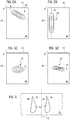
- the figure 3 sketch a first example of a blade 26 according to the invention in isometric view.
- the blade 26 includes a leading edge 40, a trailing edge 42, an upper surface 44 and a lower surface 46 (invisible on the figure 3 ). These surfaces 44, 46 are curved and extend from the leading edge 40 to the trailing edge 42.
- the representation of the blade is schematic and the camber of the upper surface and the lower surface are not necessarily at the ladder.
- the invention is here described in particular for a stator blade 26 but the same types of irregularities can be provided on a rotor blade.
- the blade 26 can be considered as a stack of cambered aerodynamic profiles, the sides of which generate the lower surface 46 and the upper surface 44.
- the contours of the profiles on the lower and / or upper surfaces may be parallel and / or tangent to the axis of rotation 14 of the compressor.
- the leading edge 40 extends in an average direction denoted A. It can be substantially radial.
- the blade 26 extends from an internal radial end called a foot 48 to an external radial end called a head 50 over a height H.
- the blade 26 includes an irregularity 52 in the form of a protuberance on the upper surface. This extends by a length L in a direction of larger dimension B which in this example is parallel to the axis 14. Transversally, that is to say according to the height of the blade 26, the protuberance 52 extends along a width l. A point denoted E is the culmination of the protuberance.
- RE can be between 25 and 75% of H or between 70 and 100% of H. Other positions not claimed are possible, for example from 0 to 30%.
- a point F is at the center of the protuberance 52, that is to say that it separates the protuberance 52 into two equal parts along the axis B of the length L.
- the protuberance 52 is represented using level lines making it possible to materialize the declivities thereof.
- the blade 26 is fixed at its foot 48 to an internal ferrule 32.
- the ferrule 32 is axisymmetric. At each point of the ferrule, the latter has a constant radius around the axis 14.
- the ferrule 32 is devoid of irregularity. Alternatively, an irregularity of the bump or hollow type can be provided on the ferrule 32.
- the figure 4 is a sectional view in a plane perpendicular to the direction A of the figure 3 and passing through E. For dawn 26 of the figure 3 , this plan includes the right indicating direction B.
- the figure 4 shows two examples of irregularity 52: a protuberance on the upper surface 44 and a recess on the lower surface 46. It is understood that the invention is not limited to this type of configuration and that upper surface 44 as lower surface 46 can indifferently be provided with none, one or more indentations / protuberances. Also, the irregularities of the upper surface and the lower surface are not limited to being positioned in the same plane and it is for the purpose of simplification that the two are represented here in the same section of the blade 26.
- Point E represents the apex of the irregularity 52. This is at a distance e, normally measured on the upper surface, e defining the thickness or amplitude of the irregularity with respect to the upper surface.
- the irregularity extends over a length L.
- the length L can be measured curvilinearly along the nominal line (dotted line) of the upper surface 44 in the absence of irregularity.
- Point F is the center of the irregularity, halfway longitudinally. For some forms of irregularities, points E and F can be confused.
- the irregularity 52 on the lower surface 46 illustrates the depth p of a recess.
- the same parameters E, F, L can be used (not shown).
- the rope is the segment which connects the leading edge 40 to the trailing edge 42.
- the length of the rope is here noted C.
- the position of point E can be identified on the rope by the parameter noted here XE.
- XE can be between 0 and 30% of C or between 0 and 50% of C. Other unclaimed positions are possible, for example from 50 to 70%.
- the Figures 5A to 5D show, according to a view normal to the upper surface 44, other examples of irregularities 52 which the upper surface 44 or the lower surface 46 of dawn can receive.
- Each of the examples can be adapted on the lower surface or the extrados, alone or in combination with other irregularities.
- the shapes shown can be applied equally to a protuberance or a recess. When the dawn includes several irregularities, these can be discontinuous or in the continuation of the flow of one another. For example, a recess may follow a protrusion or vice versa.
- the figure 5A describes an example of irregularity 52 in the vicinity of the head 50 of the blade 26.
- the irregularity 52 forms an angle of approximately 30 ° with the leading edge 40 and the point E is in the middle of the blade axially and is located about 75% of the height of dawn.
- the figure 5B describes an irregularity 52 which is substantially parallel to the leading edge 40.
- the irregularity 52 extends in height by a length of approximately half the height of the blade.
- the figure 5C shows another configuration of irregularity 52 which illustrates that the width of the irregularity may not be constant over the entire extent of the irregularity 52.
- the irregularity 52 has a teardrop shape. water. Triangular or trapezoidal shapes are also possible. The greatest width can be upstream or downstream.
- the figure 5D illustrates a variant in which the irregularity 52 has a main direction which is not linear.
- the irregularity describes an S-shaped curve.
- Such an irregularity makes it possible to cause a flow to converge radially, for example in the downstream part of a compressor, before the swan-shaped vein.
- the figure 6 illustrates in a view in radial projection, two adjacent blades of a compressor.
- the blades have a protuberance and a recess 52, respectively, which are opposite one another.
- the geometric surfaces defined by these facing irregularities are identical at least in part, one being the image of the other by rotation about the axis 14, or by translation along an axis perpendicular to the radius.
- the two blades can at least partially guide the flow identically.
Abstract
L'invention a pour objet une aube (26) de compresseur de turboréacteur, l'aube (26) comprenant un bord d'attaque (40), un bord de fuite (42), une surface extrados (44) et une surface intrados (46), remarquable en ce qu'elle comprend au moins une irrégularité (52) sous la forme d'une protubérance en saillie de l'extrados (44) ou de l'intrados (46) ou sous la forme d'un renfoncement niché dans l'extrados (44) ou l'intrados (46). L'irrégularité (52) peut avoir une forme de plus grande dimension sensiblement parallèle au bord d'attaque (40) ou sensiblement axiale.L'invention porte également sur un procédé de fabrication d'une telle aube, sur un compresseur muni d'une telle aube et sur une turbomachine axiale.The subject of the invention is a blade (26) of a turbojet compressor, the blade (26) comprising a leading edge (40), a trailing edge (42), an upper surface (44) and a lower surface (46), remarkable in that it comprises at least one irregularity (52) in the form of a protrusion projecting from the upper surface (44) or the lower surface (46) or in the form of a recess nestled in the upper surface (44) or the lower surface (46). The irregularity (52) may have a shape of larger dimension substantially parallel to the leading edge (40) or substantially axial. The invention also relates to a method of manufacturing such a blade, on a compressor provided with such a blade and on an axial turbomachine.
Description
L'invention concerne le domaine des turbomachines axiales et en particulier les compresseurs de turboréacteur d'aéronef. Plus spécifiquement, l'invention a trait à une conception particulière d'une aube pour une turbomachine axiale.The invention relates to the field of axial turbomachinery and in particular the compressors of an aircraft turbojet engine. More specifically, the invention relates to a particular design of a blade for an axial turbomachine.
Dans un compresseur de turbomachine axiale peuvent survenir des pertes aérodynamiques. Par exemple, certaines interférences entre l'écoulement proche de la virole et l'écoulement dévié au voisinage de l'aube entraîne des phénomènes dits « secondaires » qui se traduisent par des pertes et d'instabilités (« tip leakage vortex », « corner stall », ...).In an axial turbomachine compressor, aerodynamic losses can occur. For example, certain interferences between the flow near the ferrule and the flow deflected in the vicinity of dawn causes so-called "secondary" phenomena which result in losses and instabilities ("tip leakage vortex", "corner stall ", ...).
Afin d'atténuer ce phénomène, des formes d'aube différentes ont été développées, avec par exemple un effet « sweep » ou de « bow », étendant l'aube axialement ou circonférentiellement.In order to mitigate this phenomenon, different blade shapes have been developed, with for example a “sweep” or “bow” effect, extending the blade axially or circumferentially.
Aussi, il est connu de prévoir des protubérances sur les viroles internes ou externes qui supportent les aubes. Ce principe prend souvent le nom anglais de « contouring » ou « contouring 3D » car il consiste en une modification du contour de la virole. Des creux ou des bosses peuvent ainsi être conçus sur une surface de guidage du flux entre deux aubes voisines.Also, it is known to provide protuberances on the internal or external ferrules which support the blades. This principle often takes the English name of "contouring" or "3D contouring" because it consists of a modification of the contour of the shell. Hollows or bumps can thus be designed on a surface for guiding the flow between two neighboring blades.
Le document
L'invention a pour objectif de minimiser les pertes aérodynamiques pour améliorer le rendement d'une turbomachine, en particulier au niveau des aubes de compresseur.The invention aims to minimize aerodynamic losses to improve the efficiency of a turbomachine, in particular at the compressor blades.
L'invention a pour objet une aube pour compresseur de turbomachine axiale, comprenant un bord d'attaque, un bord de fuite, une surface extrados et une surface intrados, remarquable en ce qu'elle comprend au moins une irrégularité sous la forme d'une protubérance en saillie de l'extrados ou de l'intrados ou sous la forme d'un renfoncement niché dans l'extrados ou l'intrados, l'irrégularité présentant une direction de plus grande dimension sensiblement parallèle au bord d'attaque, l'irrégularité (52) présentant des variations d'épaisseur ou de profondeur selon sa direction (B) de plus grande dimension et le point (E) de l'irrégularité (52) présentant l'épaisseur ou la profondeur maximale ayant une position radiale (RE) qui est comprise entre 25 et 75% de la hauteur (H) de l'aube (26).The subject of the invention is a blade for an axial turbomachine compressor, comprising a leading edge, a trailing edge, an upper surface and a lower surface, remarkable in that it comprises at least one irregularity in the form of a protrusion protruding from the upper surface or lower surface or in the form of a recess nested in the upper surface or the lower surface, the irregularity having a direction of larger dimension substantially parallel to the leading edge, l 'irregularity (52) having variations in thickness or depth along its direction (B) of larger dimension and the point (E) of the irregularity (52) having the maximum thickness or depth having a radial position ( RE) which is between 25 and 75% of the height (H) of the blade (26).
L'irrégularité peut être un épaississement ou un amincissement de l'aube par rapport à un profil nominal. L'irrégularité est continue et progressive dans les trois directions de l'espace.The irregularity can be a thickening or thinning of the blade compared to a nominal profile. The irregularity is continuous and progressive in the three directions of space.
Comme le bord d'attaque peut être courbe, pour qualifier son orientation, il peut convenir de faire référence à sa direction moyenne.As the leading edge can be curved, to qualify its orientation, it may be appropriate to refer to its mean direction.
L'épaisseur ou la profondeur maximale est la plus grande distance entre la surface de l'irrégularité et la surface théorique nominale de l'extrados ou intrados en l'absence d'irrégularité. La présente demande utilisera indifféremment les termes d'épaisseur ou profondeur maximale aussi bien que « amplitude ».The maximum thickness or depth is the greatest distance between the surface of the irregularity and the nominal theoretical surface of the upper surface or lower surface in the absence of an irregularity. The present application will use the terms of maximum thickness or depth interchangeably as well as "amplitude".
Selon un mode avantageux de l'invention, le point de l'irrégularité présentant l'épaisseur ou la profondeur maximale a une position le long de la corde, mesurée depuis le bord d'attaque, comprise entre 0 et 30% de la corde.According to an advantageous embodiment of the invention, the point of the irregularity having the maximum thickness or depth has a position along the rope, measured from the leading edge, between 0 and 30% of the rope.
Selon un mode avantageux de l'invention, l'irrégularité présente une direction de plus grande dimension qui forme un angle compris entre 0 et 20° par rapport à la direction moyenne du bord d'attaque.According to an advantageous embodiment of the invention, the irregularity has a direction of larger dimension which forms an angle between 0 and 20 ° relative to the average direction of the leading edge.
L'invention porte également sur une aube pour compresseur de turbomachine axiale, comprenant un bord d'attaque, un bord de fuite, une surface extrados et une surface intrados, remarquable en ce qu'elle comprend au moins une irrégularité sous la forme d'une protubérance en saillie de l'extrados ou de l'intrados ou sous la forme d'un renfoncement niché dans l'extrados ou l'intrados, l'irrégularité étant circonscrite à la moitié radiale externe de l'aube et présentant une direction de plus grande dimension qui est sensiblement axiale l'irrégularité étant venue de matière avec l'aube et étant apte à former une surface de guidage de l'air.The invention also relates to a blade for an axial turbomachine compressor, comprising a leading edge, a trailing edge, an upper surface and a lower surface, remarkable in that it comprises at least one irregularity in the form of a protrusion protruding from the upper surface or lower surface or in the form of a recess nested in the upper surface or the lower surface, the irregularity being circumscribed to the outer radial half of the blade and having a direction of larger dimension which is substantially axial, the irregularity having come in one piece with the blade and being capable of forming an air guide surface.
Selon un mode avantageux de l'invention, le point de l'irrégularité présentant l'épaisseur ou la profondeur maximale a une position radiale qui est comprise entre 70 et 100% de la hauteur de l'aube.According to an advantageous embodiment of the invention, the point of the irregularity having the maximum thickness or depth has a radial position which is between 70 and 100% of the height of the blade.
Selon un mode avantageux de l'invention, le point de l'irrégularité présentant l'épaisseur ou la profondeur maximale a une position le long de la corde, mesurée depuis le bord d'attaque, comprise entre 0 et 50% de la corde.According to an advantageous embodiment of the invention, the point of the irregularity having the maximum thickness or depth has a position along the rope, measured from the leading edge, between 0 and 50% of the rope.
En d'autres termes, l'irrégularité est dans ce cas majoritairement dans la partie amont de l'aube.In other words, the irregularity is in this case mainly in the upstream part of the dawn.
Selon un mode avantageux de l'invention, l'irrégularité présente une direction de plus grande dimension qui forme un angle compris entre 45 et 90° avec la direction moyenne du bord d'attaque.According to an advantageous embodiment of the invention, the irregularity has a direction of larger dimension which forms an angle between 45 and 90 ° with the mean direction of the leading edge.
Selon un mode avantageux de l'invention, le facteur de forme de l'irrégularité est supérieur à deux.According to an advantageous embodiment of the invention, the form factor of the irregularity is greater than two.
Le facteur de forme est le ratio entre la dimension de l'irrégularité dans la direction de plus grande dimension et sa dimension dans la direction de seconde plus grande dimension. Les dimensions de l'irrégularité peuvent être mesurées curvilignement le long de l'extrados ou de l'intrados.The form factor is the ratio between the dimension of the irregularity in the direction of larger dimension and its dimension in the direction of second larger dimension. The dimensions of the irregularity can be measured curvilinearly along the upper or lower surface.
Selon un mode avantageux de l'invention, l'aube comprend un pied et une tête définissant les extrémités radiales de l'aube, l'irrégularité étant à une distance du pied et de la tête de l'aube d'au moins 5% de la hauteur radiale de l'aube.According to an advantageous embodiment of the invention, the blade comprises a foot and a head defining the radial ends of the blade, the irregularity being at a distance from the foot and the head of the blade of at least 5% the radial height of the blade.
Ainsi, l'irrégularité est éloignée de la jonction entre l'aube et la virole. Aussi, elle ne forme pas de continuité avec un contouring sur la virole.Thus, the irregularity is far from the junction between the dawn and the shell. Also, it does not form continuity with a contouring on the shell.
Selon un mode avantageux de l'invention, l'épaisseur ou la profondeur maximale de l'irrégularité, mesurée selon la normale à l'extrados ou l'intrados est comprise entre 1 et 15% de l'épaisseur de l'aube au droit du point de l'irrégularité présentant l'épaisseur ou la profondeur maximale.According to an advantageous embodiment of the invention, the maximum thickness or depth of the irregularity, measured according to the normal on the upper surface or the lower surface is between 1 and 15% of the thickness of the blade at right from the point of irregularity with maximum thickness or depth.
En pratique, l'amplitude des irrégularités peut donc être comprise entre quelques centièmes de millimètres et 1 ou 2 mm au plus.In practice, the amplitude of the irregularities can therefore be between a few hundredths of a millimeter and 1 or 2 mm at most.
Selon un mode avantageux de l'invention, l'irrégularité est asymétrique, le point milieu de l'irrégularité dans la direction de plus grande dimension étant préférentiellement en amont du point présentant l'épaisseur ou la profondeur maximale.According to an advantageous embodiment of the invention, the irregularity is asymmetrical, the midpoint of the irregularity in the direction of greatest dimension being preferably upstream of the point having the maximum thickness or depth.
Cette forme permet de dévier progressivement le flux d'amont vers l'aval.This shape allows to gradually divert the flow from upstream to downstream.
Alternativement, une forme contraire peut être avantageuse en « sur-déviant » le flux en amont puis en revenant vers l'aube rapidement vers l'aval.Alternatively, an opposite shape can be advantageous by "over-deflecting" the flow upstream and then returning towards dawn quickly downstream.
Selon un mode avantageux de l'invention, l'irrégularité s'étend principalement selon une direction non-linéaire, éventuellement en forme de S. Ainsi, vu depuis une direction circonférentielle ou normale à l'extrados ou l'intrados, l'irrégularité peut avoir une forme en S.According to an advantageous embodiment of the invention, the irregularity extends mainly in a non-linear direction, possibly in the form of an S. Thus, seen from a circumferential or normal direction on the upper surface or the lower surface, the irregularity may have an S shape.
Selon un mode avantageux de l'invention, l'irrégularité présente une variation de largeur. L'irrégularité peut avoir une largeur plus importante en amont qu'en aval ou inversement. La différence entre sa largeur amont et sa largeur aval peut être d'au moins 20%.According to an advantageous embodiment of the invention, the irregularity presents a variation in width. The irregularity may have a greater width upstream than downstream or vice versa. The difference between its upstream width and its downstream width can be at least 20%.
Selon un mode avantageux de l'invention, l'irrégularité comprend une pluralité de points pour lesquels l'épaisseur ou la profondeur de l'irrégularité est maximale. Ainsi, l'irrégularité peut comprendre une courbe ou une surface parallèle à l'extrados ou l'intrados, formant ainsi un plateau.According to an advantageous embodiment of the invention, the irregularity comprises a plurality of points for which the thickness or the depth of the irregularity is maximum. Thus, the irregularity may include a curve or a surface parallel to the upper surface or the lower surface, thus forming a plateau.
Selon un mode avantageux de l'invention, l'irrégularité forme avec l'extrados ou l'intrados une surface continue et dérivable. Ainsi, il n'y a pas de point anguleux ou d'arête anguleuse, ni sur l'irrégularité elle-même, ni à la surface de jonction entre l'irrégularité et l'extrados ou l'intrados, et ce dans les trois directions de l'espace.According to an advantageous embodiment of the invention, the irregularity forms with the upper surface or the lower surface a continuous and derivable surface. Thus, there is no angular point or angular edge, neither on the irregularity itself, nor on the junction surface between the irregularity and the upper surface or the lower surface, and this in the three directions from space.
L'invention porte également sur un procédé de fabrication d'une aube, remarquable en ce qu'il comprend une étape de fabrication d'une aube telle que décrite ci-dessus par un procédé de fabrication additive.The invention also relates to a method of manufacturing a blade, remarkable in that it comprises a step of manufacturing a blade as described above by an additive manufacturing method.
La fabrication additive permet en particulier d'obtenir des formes d'irrégularités que ne permettent pas d'obtenir les procédés usuels tels que la déformation plastique et l'usinage.Additive manufacturing makes it possible in particular to obtain forms of irregularities that do not make it possible to obtain the usual methods such as plastic deformation and machining.
L'invention porte également sur un compresseur de turbomachine, comprenant au moins une rangée d'aubes rotoriques et au moins une rangée d'aubes statoriques, le compresseur étant caractérisé en ce qu'au moins une des aubes rotoriques ou statoriques est selon l'un des modes de réalisation décrit ci-dessus.The invention also relates to a turbomachine compressor, comprising at least one row of rotor blades and at least one row of stator blades, the compressor being characterized in that at least one of the rotor or stator blades is according to the one of the embodiments described above.
Selon un mode avantageux de l'invention, les aubes sont portées par une virole interne et/ou une virole externe, les viroles présentant entre deux aubes circonférentiellement adjacentes une surface régulière cylindrique ou conique.According to an advantageous embodiment of the invention, the vanes are carried by an internal ferrule and / or an external ferrule, the ferrules having between two circumferentially adjacent vanes a regular cylindrical or conical surface.
Par surface régulière, on entend une surface dépourvue d'irrégularité. Seule les extrados ou intrados des aubes sont pourvus d'irrégularité sans qu'ils ne constituent une continuité d'un contouring sur une virole.By regular surface is meant a surface without irregularity. Only the extrados or intrados of the blades are provided with irregularity without them constituting a continuity of a contouring on a ferrule.
Selon un mode avantageux de l'invention, le compresseur comprend deux aubes circonférentiellement adjacentes et présentant chacune une irrégularité sur la face extrados et intrados en regard de l'autre aube, l'irrégularité sur l'extrados d'une des aubes formant une première surface et l'irrégularité sur l'intrados de l'autre aube formant une seconde surface, les première et seconde surfaces étant parallèles ou étant l'une l'image de l'autre par rotation autour de l'axe du compresseur, au moins en partie.According to an advantageous embodiment of the invention, the compressor comprises two circumferentially adjacent blades, each having an irregularity on the upper and lower surface facing the other blade, the irregularity on the upper surface of one of the blades forming a first surface and the irregularity on the lower surface of the other blade forming a second surface, the first and second surfaces being parallel or being one the image of the other by rotation around the axis of the compressor, at least in part.
L'invention porte également sur une turbomachine, notamment un turboréacteur d'aéronef, comprenant un compresseur, remarquable en ce que le compresseur est conforme à l'un des modes de réalisation ci-dessus, le compresseur comprenant au moins : cinquante, ou quatre-vingt, ou cent aubes (26) selon l'une des variantes exposées ci-dessus.The invention also relates to a turbomachine, in particular an aircraft turbojet engine, comprising a compressor, remarkable in that the compressor conforms to one of the above embodiments, the compressor comprising at least: fifty, or four -twenty, or one hundred blades (26) according to one of the variants set out above.
De manière générale, les modes avantageux de chaque objet de l'invention sont également applicables aux autres objets de l'invention. Chaque objet de l'invention est combinable aux autres objets, et les objets de l'invention sont également combinables aux modes de réalisation de la description, qui en plus sont combinables entre eux, selon toutes les combinaisons techniques possibles, à moins que le contraire ne soit explicitement mentionné.In general, the advantageous modes of each object of the invention are also applicable to the other objects of the invention. Each object of the invention can be combined with other objects, and the objects of the invention can also be combined with the embodiments of the description, which in addition can be combined with one another, according to all possible technical combinations, unless the opposite is explicitly stated. mentionned.
En particulier, une aube peut comprendre plusieurs irrégularités selon les variantes exposées ci-dessus sur ses surfaces extrados et intrados.In particular, a blade may include several irregularities according to the variants set out above on its upper and lower surfaces.
L'invention permet de recadrer le flux dans le passage. L'irrégularité tend à limiter les décollements du flux d'air. Le débit traversant la grille d'aubes peut augmenter tout en évitant les phénomènes de pompage.The invention makes it possible to crop the flow in the passage. The irregularity tends to limit detachments from the air flow. The flow rate passing through the blade grid can increase while avoiding pumping phenomena.
L'invention permet également de proposer une solution simple, résistante, légère, économique, fiable, facile à produire, commode d'entretien et d'inspection aisée.The invention also makes it possible to propose a simple, resistant, light, economical, reliable, easy to produce, convenient maintenance and easy inspection solution.
Les conceptions présentées dans la présente invention permettent également l'augmentation de la stabilité mécanique et aérodynamique de l'aubage.The designs presented in the present invention also allow the mechanical and aerodynamic stability of the blading to be increased.
-
La
figure 1 représente une turbomachine axiale selon l'invention ;Thefigure 1 represents an axial turbomachine according to the invention; -
La
figure 2 est un schéma d'un compresseur de turbomachine selon l'invention ;Thefigure 2 is a diagram of a turbomachine compressor according to the invention; -
La
figure 3 illustre une vue isométrique d'une aube selon l'invention présentant une irrégularité sur son extrados ;Thefigure 3 illustrates an isometric view of a blade according to the invention having an irregularity on its upper surface; -
La
figure 4 présente une section de l'aube de lafigure 3 dans un plan perpendiculaire à la direction principale de l'aube ;Thefigure 4 presents a section of the dawn of thefigure 3 in a plane perpendicular to the main direction of dawn; -
Les
figures 5A à 5D illustrent divers exemples d'irrégularités ;TheFigures 5A to 5D illustrate various examples of irregularities; -
La
figure 6 représente une partie de compresseur avec deux aubes adjacentes.Thefigure 6 represents a compressor part with two adjacent blades.
Dans la description qui va suivre, les termes « interne » et « externe » renvoient à un positionnement par rapport à l'axe de rotation d'une turbomachine axiale. La direction axiale correspond à la direction le long de l'axe de rotation de la turbomachine. La direction radiale est perpendiculaire à l'axe de rotation. La hauteur fait référence à une dimension radiale. L'amont et l'aval sont en référence au sens d'écoulement principal du flux dans la turbomachine. La longueur est la plus grande dimension d'un élément, la largeur est sa seconde plus grande dimension.In the following description, the terms "internal" and "external" refer to a positioning relative to the axis of rotation of an axial turbomachine. The axial direction corresponds to the direction along the axis of rotation of the turbomachine. The radial direction is perpendicular to the axis of rotation. Height refers to a radial dimension. Upstream and downstream are in reference to the main flow direction of the flow in the turbomachine. Length is the largest dimension of an element, width is its second largest dimension.
Il est à noter que les figures et notamment celles représentant la protubérance ou le renfoncement de l'aube, ne sont pas dessinées à l'échelle et que les dimensions peuvent être exagérées pour représenter plus clairement certains aspects de l'invention.It should be noted that the figures and in particular those representing the protuberance or the recess of the dawn, are not drawn to scale and that the dimensions can be exaggerated to more clearly represent certain aspects of the invention.
La
Un ventilateur d'entrée communément désigné fan ou soufflante 16 est couplé au rotor 12, éventuellement via un réducteur épicycloïdal (non représenté), et génère un flux d'air qui se divise en un flux primaire 18 traversant les différents niveaux susmentionnés de la turbomachine, et en un flux secondaire 20 traversant un conduit annulaire (partiellement représenté) le long de la machine pour ensuite rejoindre le flux primaire en sortie de turbine.An inlet fan commonly designated as a fan or
Le flux secondaire peut être accéléré de sorte à générer une réaction de poussée nécessaire au vol d'un avion. Les flux primaire 18 et secondaire 20 sont des flux annulaires coaxiaux et emmanchés l'un dans l'autre. Ils sont canalisés par le carter de la turbomachine et/ou des viroles.The secondary flow can be accelerated so as to generate a thrust reaction necessary for the flight of an aircraft. The primary 18 and secondary 20 flows are annular coaxial flows and fitted one inside the other. They are channeled through the casing of the turbomachine and / or of the ferrules.
La
Le rotor 12 comprend plusieurs rangées d'aubes rotoriques 24, en l'occurrence trois. Il peut être un tambour monobloc aubagé, ou comprendre des aubes à fixation par queue d'aronde. Les aubes rotoriques 24 peuvent s'étendre radialement depuis une plateforme individuelle, ou depuis une couronne interne 25 du rotor 12.The
Le compresseur basse-pression 4 comprend plusieurs redresseurs, en l'occurrence quatre, qui contiennent chacun une rangée d'aubes statoriques 26. Les redresseurs sont associés au fan 16 ou à une rangée d'aubes rotoriques pour redresser le flux d'air, de sorte à convertir la vitesse du flux en pression, notamment en pression statique.The low-
Les aubes statoriques 26 s'étendent essentiellement radialement depuis un carter extérieur 28, et peuvent y être fixées et immobilisées à l'aide d'axes 30. Alternativement, les aubes peuvent être collées. Elles traversent radialement le flux primaire 18. Leurs pales peuvent traverser la paroi annulaire du carter extérieur 28. Au sein d'une même rangée, les aubes statoriques 26 sont régulièrement espacées les unes des autres, et présentent une même orientation angulaire dans le flux 18. Leurs cordes peuvent présenter une inclinaison fixe par rapport à l'axe de rotation 14. Avantageusement, les aubes d'une même rangée sont identiques et alignées. Chaque rangée d'aubes 26, 24 peut comprendre de cinquante à cent ou cent vingt unités.The stator vanes 26 extend essentially radially from an
Des viroles internes 32 peuvent être suspendues aux extrémités internes des aubes statoriques 26. Les viroles internes 32 peuvent coopérer de manière étanche avec le rotor 12 afin d'améliorer le taux de compression du compresseur 4.
La
L'aube 26 peut être considérée comme un empilement de profils aérodynamiques cambrés, dont les côtés génèrent la surface intrados 46 et la surface extrados 44. A l'approche du bord de fuite 42, les contours des profils en intrados et/ou en extrados, peuvent être parallèles et/ou tangents à l'axe de rotation 14 du compresseur.The
Le bord d'attaque 40 s'étend selon une direction moyenne notée A. Elle peut être sensiblement radiale.The leading
L'aube 26 s'étend d'une extrémité radiale interne dite pied 48 à une extrémité radiale externe dite tête 50 sur une hauteur H.The
Sur cet exemple, l'aube 26 comprend une irrégularité 52 sous la forme d'une protubérance sur l'extrados. Celle-ci s'étend d'une longueur L selon une direction de plus grande dimension B qui dans cet exemple est parallèle à l'axe 14. Transversalement, c'est-à-dire selon la hauteur de l'aube 26, la protubérance 52 s'étend selon une largeur l. Un point noté E est le point culminant de la protubérance.In this example, the
La position radiale du point E peut être repérée radialement par rapport au pied de l'aube 48 par le paramètre RE. Selon diverses modes de réalisation de l'invention, RE peut être compris entre 25 et 75% de H ou entre 70 et 100% de H. D'autres positions non revendiquées sont possibles, par exemple de 0 à 30%.The radial position of the point E can be identified radially with respect to the root of the
Un point F est au centre de la protubérance 52, c'est-à-dire qu'il sépare la protubérance 52 en deux parts égales selon l'axe B de la longueur L.A point F is at the center of the
La protubérance 52 est représentée à l'aide de lignes de niveau permettant de matérialiser les déclivités de celle-ci.The
L'aube 26 est fixée au niveau de son pied 48 à une virole interne 32. La virole 32 est axisymétrique. En chaque point de la virole, celle-ci présente un rayon constant autour de l'axe 14. La virole 32 est dépourvue d'irrégularité. Alternativement, une irrégularité du type bosse ou creux peut être prévue sur la virole 32.The
La
La
Le point E représente le sommet de l'irrégularité 52. Celui-ci est à une distance e, mesurée normalement à l'extrados, e définissant l'épaisseur ou amplitude de l'irrégularité par rapport à l'extrados.Point E represents the apex of the
L'irrégularité s'étend sur une longueur L. La longueur L peut être mesurée curvilignement selon la ligne nominale (en pointillés) de l'extrados 44 en absence d'irrégularité.The irregularity extends over a length L. The length L can be measured curvilinearly along the nominal line (dotted line) of the
Le point F est le centre de l'irrégularité, à mi-chemin longitudinalement. Pour certaines formes d'irrégularités, les points E et F peuvent être confondus.Point F is the center of the irregularity, halfway longitudinally. For some forms of irregularities, points E and F can be confused.
L'irrégularité 52 du côté intrados 46 illustre la profondeur p d'un renfoncement. Les mêmes paramètres E, F, L peuvent être utilisés (non représentés).The
La corde est le segment qui relie le bord d'attaque 40 au bord de fuite 42. La longueur de la corde est ici notée C. La position du point E peut être repérée sur la corde par le paramètre noté ici XE.The rope is the segment which connects the leading
Selon diverses modes de réalisation de l'invention, XE peut être compris entre 0 et 30% de C ou entre 0 et 50% de C. D'autres positions non revendiquées sont possibles, par exemple de 50 à 70%.According to various embodiments of the invention, XE can be between 0 and 30% of C or between 0 and 50% of C. Other unclaimed positions are possible, for example from 50 to 70%.
Les
La
La
La
La
La
Claims (15)
Applications Claiming Priority (1)
| Application Number | Priority Date | Filing Date | Title |
|---|---|---|---|
| BE20185606A BE1026579B1 (en) | 2018-08-31 | 2018-08-31 | PROTUBERANCE VANE FOR TURBOMACHINE COMPRESSOR |
Publications (1)
| Publication Number | Publication Date |
|---|---|
| EP3617527A1 true EP3617527A1 (en) | 2020-03-04 |
Family
ID=63713569
Family Applications (1)
| Application Number | Title | Priority Date | Filing Date |
|---|---|---|---|
| EP19189950.9A Pending EP3617527A1 (en) | 2018-08-31 | 2019-08-05 | Vane with projection for a turbine engine compressor |
Country Status (4)
| Country | Link |
|---|---|
| US (1) | US11203935B2 (en) |
| EP (1) | EP3617527A1 (en) |
| CN (1) | CN110873075B (en) |
| BE (1) | BE1026579B1 (en) |
Cited By (1)
| Publication number | Priority date | Publication date | Assignee | Title |
|---|---|---|---|---|
| DE102020202978A1 (en) | 2020-03-09 | 2021-09-09 | MTU Aero Engines AG | COMPONENT FOR A FLOW MACHINE |
Families Citing this family (2)
| Publication number | Priority date | Publication date | Assignee | Title |
|---|---|---|---|---|
| CN112228401A (en) * | 2020-09-30 | 2021-01-15 | 大连海事大学 | Slotted vane diffuser |
| US20240125241A1 (en) * | 2022-10-05 | 2024-04-18 | Raytheon Technologies Corporation | Axial compressor stator |
Citations (19)
| Publication number | Priority date | Publication date | Assignee | Title |
|---|---|---|---|---|
| GB750305A (en) * | 1953-02-05 | 1956-06-13 | Rolls Royce | Improvements in axial-flow compressor, turbine and like blades |
| US3014640A (en) * | 1958-06-09 | 1961-12-26 | Gen Motors Corp | Axial flow compressor |
| US3653110A (en) * | 1970-01-05 | 1972-04-04 | North American Rockwell | Method of fabricating hollow blades |
| FR2114693A5 (en) * | 1970-11-16 | 1972-06-30 | United Aircraft Canada | |
| DE2135287A1 (en) * | 1971-07-15 | 1973-01-25 | Wilhelm Prof Dr Ing Dettmering | RUNNER AND GUIDE WHEEL GRILLE FOR TURBO MACHINERY |
| GB2032048A (en) * | 1978-07-15 | 1980-04-30 | English Electric Co Ltd | Boundary layer control device |
| GB2033022A (en) * | 1978-11-02 | 1980-05-14 | Gen Electric | Turbomachinery blade |
| US4720239A (en) * | 1982-10-22 | 1988-01-19 | Owczarek Jerzy A | Stator blades of turbomachines |
| US5288209A (en) * | 1991-12-19 | 1994-02-22 | General Electric Company | Automatic adaptive sculptured machining |
| JPH0711901A (en) * | 1993-06-29 | 1995-01-13 | Ishikawajima Harima Heavy Ind Co Ltd | Separation control blade |
| EP0976928A2 (en) * | 1998-07-31 | 2000-02-02 | DLR Deutsches Zentrum für Luft- und Raumfahrt e.V. | Blade assembly for turbomachine |
| US6183197B1 (en) * | 1999-02-22 | 2001-02-06 | General Electric Company | Airfoil with reduced heat load |
| FR2867506A1 (en) * | 2004-03-11 | 2005-09-16 | Snecma Moteurs | Guide vane for use on stator of jet engine, has rib directed in direction of gas flow traversing vane for dampening vibrations of vane, and placed at back side of vane closer to trailing edge than leading edge of vane |
| EP2019186A1 (en) * | 2006-04-17 | 2009-01-28 | IHI Corporation | Blade |
| US20090185911A1 (en) * | 2008-01-23 | 2009-07-23 | United Technologies Corp. | Systems and Methods Involving Localized Stiffening of Blades |
| EP2093378A1 (en) * | 2008-02-25 | 2009-08-26 | ALSTOM Technology Ltd | Upgrading method for a blade by retrofitting a winglet, and correspondingly upgraded blade |
| US20120128480A1 (en) * | 2009-08-06 | 2012-05-24 | Mtu Aero Engines Gmbh | Blade |
| US20130101409A1 (en) | 2011-10-25 | 2013-04-25 | Alexander R. Beeck | Turbine component including airfoil with contour |
| US20160024930A1 (en) * | 2014-07-24 | 2016-01-28 | General Electric Company | Turbomachine airfoil |
Family Cites Families (81)
| Publication number | Priority date | Publication date | Assignee | Title |
|---|---|---|---|---|
| US3012709A (en) * | 1955-05-18 | 1961-12-12 | Daimler Benz Ag | Blade for axial compressors |
| US3077173A (en) * | 1960-03-09 | 1963-02-12 | Thomas G Lang | Base ventilated hydrofoil |
| US3409968A (en) * | 1966-10-03 | 1968-11-12 | Borg Warner | Method of making a slotted blade by extruding |
| US3748721A (en) * | 1970-03-18 | 1973-07-31 | Trw Inc | Method of making composites |
| US3973870A (en) * | 1974-11-04 | 1976-08-10 | Westinghouse Electric Corporation | Internal moisture removal scheme for low pressure axial flow steam turbine |
| US4108573A (en) * | 1977-01-26 | 1978-08-22 | Westinghouse Electric Corp. | Vibratory tuning of rotatable blades for elastic fluid machines |
| US4830315A (en) * | 1986-04-30 | 1989-05-16 | United Technologies Corporation | Airfoil-shaped body |
| US5704763A (en) * | 1990-08-01 | 1998-01-06 | General Electric Company | Shear jet cooling passages for internally cooled machine elements |
| US5112187A (en) * | 1990-09-12 | 1992-05-12 | Westinghouse Electric Corp. | Erosion control through reduction of moisture transport by secondary flow |
| US5395071A (en) * | 1993-09-09 | 1995-03-07 | Felix; Frederick L. | Airfoil with bicambered surface |
| ATE200139T1 (en) * | 1995-12-12 | 2001-04-15 | Roche Ulrich | METHOD FOR FORMING A SURFACE FOR CONTACT WITH A FLOWING FLUID AND BODY WITH APPROPRIATELY DESIGNED SURFACE AREAS |
| US5931641A (en) * | 1997-04-25 | 1999-08-03 | General Electric Company | Steam turbine blade having areas of different densities |
| EP1006263B1 (en) * | 1998-11-30 | 2004-01-07 | ALSTOM (Switzerland) Ltd | Vane cooling |
| DE19913269A1 (en) * | 1999-03-24 | 2000-09-28 | Asea Brown Boveri | Turbine blade |
| EP1250516B1 (en) * | 2000-01-06 | 2010-08-04 | Damping Technologies, Inc. | Turbine engine damper |
| JP2001271602A (en) * | 2000-03-27 | 2001-10-05 | Honda Motor Co Ltd | Gas turbine engine |
| US6358012B1 (en) * | 2000-05-01 | 2002-03-19 | United Technologies Corporation | High efficiency turbomachinery blade |
| US6607359B2 (en) * | 2001-03-02 | 2003-08-19 | Hood Technology Corporation | Apparatus for passive damping of flexural blade vibration in turbo-machinery |
| US6733240B2 (en) * | 2001-07-18 | 2004-05-11 | General Electric Company | Serrated fan blade |
| US6969232B2 (en) * | 2002-10-23 | 2005-11-29 | United Technologies Corporation | Flow directing device |
| US6976826B2 (en) * | 2003-05-29 | 2005-12-20 | Pratt & Whitney Canada Corp. | Turbine blade dimple |
| GB0315975D0 (en) * | 2003-07-09 | 2003-08-13 | Rolls Royce Plc | Guide vane |
| US6905309B2 (en) * | 2003-08-28 | 2005-06-14 | General Electric Company | Methods and apparatus for reducing vibrations induced to compressor airfoils |
| DE10352253A1 (en) * | 2003-11-08 | 2005-06-09 | Alstom Technology Ltd | Compressor blade |
| US7878759B2 (en) * | 2003-12-20 | 2011-02-01 | Rolls-Royce Deutschland Ltd & Co Kg | Mitigation of unsteady peak fan blade and disc stresses in turbofan engines through the use of flow control devices to stabilize boundary layer characteristics |
| US7220103B2 (en) * | 2004-10-18 | 2007-05-22 | United Technologies Corporation | Impingement cooling of large fillet of an airfoil |
| US7217096B2 (en) * | 2004-12-13 | 2007-05-15 | General Electric Company | Fillet energized turbine stage |
| US7134842B2 (en) * | 2004-12-24 | 2006-11-14 | General Electric Company | Scalloped surface turbine stage |
| US7249933B2 (en) * | 2005-01-10 | 2007-07-31 | General Electric Company | Funnel fillet turbine stage |
| US7220100B2 (en) * | 2005-04-14 | 2007-05-22 | General Electric Company | Crescentic ramp turbine stage |
| US7887297B2 (en) * | 2006-05-02 | 2011-02-15 | United Technologies Corporation | Airfoil array with an endwall protrusion and components of the array |
| US8511978B2 (en) * | 2006-05-02 | 2013-08-20 | United Technologies Corporation | Airfoil array with an endwall depression and components of the array |
| FR2907157A1 (en) * | 2006-10-13 | 2008-04-18 | Snecma Sa | MOBILE AUB OF TURBOMACHINE |
| US7600979B2 (en) * | 2006-11-28 | 2009-10-13 | General Electric Company | CMC articles having small complex features |
| DE102008020673B4 (en) * | 2007-05-09 | 2018-10-31 | Schaeffler Technologies AG & Co. KG | Graded stator blade |
| US8083487B2 (en) * | 2007-07-09 | 2011-12-27 | General Electric Company | Rotary airfoils and method for fabricating same |
| FR2928172B1 (en) * | 2008-02-28 | 2015-07-17 | Snecma | DAWN WITH NON AXISYMETRIC LINEAR PLATFORM. |
| US8167572B2 (en) * | 2008-07-14 | 2012-05-01 | Pratt & Whitney Canada Corp. | Dynamically tuned turbine blade growth pocket |
| EP2146054A1 (en) * | 2008-07-17 | 2010-01-20 | Siemens Aktiengesellschaft | Axial turbine for a gas turbine |
| DE102008033861A1 (en) * | 2008-07-19 | 2010-01-21 | Mtu Aero Engines Gmbh | Shovel of a turbomachine with vortex generator |
| US8459956B2 (en) * | 2008-12-24 | 2013-06-11 | General Electric Company | Curved platform turbine blade |
| US8186965B2 (en) * | 2009-05-27 | 2012-05-29 | General Electric Company | Recovery tip turbine blade |
| US8393872B2 (en) * | 2009-10-23 | 2013-03-12 | General Electric Company | Turbine airfoil |
| DE102009057987B4 (en) * | 2009-12-11 | 2020-08-20 | BMTS Technology GmbH & Co. KG | Loading device and guide vane for such a loading device |
| GB201003084D0 (en) * | 2010-02-24 | 2010-04-14 | Rolls Royce Plc | An aerofoil |
| US8573541B2 (en) * | 2010-09-13 | 2013-11-05 | John Sullivan | Wavy airfoil |
| FR2969230B1 (en) * | 2010-12-15 | 2014-11-21 | Snecma | COMPRESSOR BLADE WITH IMPROVED STACKING LAW |
| EP2538024B1 (en) * | 2011-06-24 | 2015-09-23 | Alstom Technology Ltd | Blade of a turbomaschine |
| DE102011083778A1 (en) * | 2011-09-29 | 2013-04-04 | Rolls-Royce Deutschland Ltd & Co Kg | Blade of a rotor or stator series for use in a turbomachine |
| US9121294B2 (en) * | 2011-12-20 | 2015-09-01 | General Electric Company | Fan blade with composite core and wavy wall trailing edge cladding |
| US9249666B2 (en) * | 2011-12-22 | 2016-02-02 | General Electric Company | Airfoils for wake desensitization and method for fabricating same |
| US8944774B2 (en) * | 2012-01-03 | 2015-02-03 | General Electric Company | Gas turbine nozzle with a flow fence |
| US9062554B2 (en) * | 2012-01-03 | 2015-06-23 | General Electric Company | Gas turbine nozzle with a flow groove |
| US9085985B2 (en) * | 2012-03-23 | 2015-07-21 | General Electric Company | Scalloped surface turbine stage |
| US9212558B2 (en) * | 2012-09-28 | 2015-12-15 | United Technologies Corporation | Endwall contouring |
| US9188017B2 (en) * | 2012-12-18 | 2015-11-17 | United Technologies Corporation | Airfoil assembly with paired endwall contouring |
| US9057276B2 (en) * | 2013-02-06 | 2015-06-16 | Siemens Aktiengesellschaft | Twisted gas turbine engine airfoil having a twisted rib |
| CN104937236B (en) * | 2013-02-21 | 2018-10-30 | 三菱重工业株式会社 | Turbine rotor blade |
| US9896950B2 (en) * | 2013-09-09 | 2018-02-20 | Rolls-Royce Deutschland Ltd & Co Kg | Turbine guide wheel |
| US9670781B2 (en) * | 2013-09-17 | 2017-06-06 | Honeywell International Inc. | Gas turbine engines with turbine rotor blades having improved platform edges |
| FR3011888B1 (en) * | 2013-10-11 | 2018-04-20 | Snecma | TURBOMACHINE PIECE WITH NON-AXISYMETRIC SURFACE |
| US9551226B2 (en) * | 2013-10-23 | 2017-01-24 | General Electric Company | Turbine bucket with endwall contour and airfoil profile |
| WO2015126449A1 (en) * | 2014-02-19 | 2015-08-27 | United Technologies Corporation | Gas turbine engine airfoil |
| US9650914B2 (en) * | 2014-02-28 | 2017-05-16 | Pratt & Whitney Canada Corp. | Turbine blade for a gas turbine engine |
| US20150275675A1 (en) * | 2014-03-27 | 2015-10-01 | General Electric Company | Bucket airfoil for a turbomachine |
| EP2987956A1 (en) * | 2014-08-18 | 2016-02-24 | Siemens Aktiengesellschaft | Compressor aerofoil |
| US9845684B2 (en) * | 2014-11-25 | 2017-12-19 | Pratt & Whitney Canada Corp. | Airfoil with stepped spanwise thickness distribution |
| FR3043428B1 (en) * | 2015-11-10 | 2020-05-29 | Safran Aircraft Engines | TURBOMACHINE RECTIFIER DAWN |
| US20170159442A1 (en) * | 2015-12-02 | 2017-06-08 | United Technologies Corporation | Coated and uncoated surface-modified airfoils for a gas turbine engine component and methods for controlling the direction of incident energy reflection from an airfoil |
| DE102015224283A1 (en) * | 2015-12-04 | 2017-06-08 | MTU Aero Engines AG | Guide vane cluster for a turbomachine |
| US10215194B2 (en) * | 2015-12-21 | 2019-02-26 | Pratt & Whitney Canada Corp. | Mistuned fan |
| US10132169B2 (en) * | 2015-12-28 | 2018-11-20 | General Electric Company | Shrouded turbine rotor blades |
| US10480323B2 (en) * | 2016-01-12 | 2019-11-19 | United Technologies Corporation | Gas turbine engine turbine blade airfoil profile |
| US10450867B2 (en) * | 2016-02-12 | 2019-10-22 | General Electric Company | Riblets for a flowpath surface of a turbomachine |
| US10465520B2 (en) * | 2016-07-22 | 2019-11-05 | General Electric Company | Blade with corrugated outer surface(s) |
| US10436037B2 (en) * | 2016-07-22 | 2019-10-08 | General Electric Company | Blade with parallel corrugated surfaces on inner and outer surfaces |
| US10895161B2 (en) * | 2016-10-28 | 2021-01-19 | Honeywell International Inc. | Gas turbine engine airfoils having multimodal thickness distributions |
| US10907648B2 (en) * | 2016-10-28 | 2021-02-02 | Honeywell International Inc. | Airfoil with maximum thickness distribution for robustness |
| GB201716178D0 (en) * | 2017-10-04 | 2017-11-15 | Rolls Royce Plc | Blade or vane for a gas turbine engine |
| BE1025668B1 (en) * | 2017-10-26 | 2019-05-27 | Safran Aero Boosters S.A. | DAMPER VIROLET FOR TURBOMACHINE COMPRESSOR |
| US10605087B2 (en) * | 2017-12-14 | 2020-03-31 | United Technologies Corporation | CMC component with flowpath surface ribs |
-
2018
- 2018-08-31 BE BE20185606A patent/BE1026579B1/en active IP Right Grant
-
2019
- 2019-08-05 EP EP19189950.9A patent/EP3617527A1/en active Pending
- 2019-08-28 CN CN201910800397.5A patent/CN110873075B/en active Active
- 2019-08-30 US US16/556,586 patent/US11203935B2/en active Active
Patent Citations (19)
| Publication number | Priority date | Publication date | Assignee | Title |
|---|---|---|---|---|
| GB750305A (en) * | 1953-02-05 | 1956-06-13 | Rolls Royce | Improvements in axial-flow compressor, turbine and like blades |
| US3014640A (en) * | 1958-06-09 | 1961-12-26 | Gen Motors Corp | Axial flow compressor |
| US3653110A (en) * | 1970-01-05 | 1972-04-04 | North American Rockwell | Method of fabricating hollow blades |
| FR2114693A5 (en) * | 1970-11-16 | 1972-06-30 | United Aircraft Canada | |
| DE2135287A1 (en) * | 1971-07-15 | 1973-01-25 | Wilhelm Prof Dr Ing Dettmering | RUNNER AND GUIDE WHEEL GRILLE FOR TURBO MACHINERY |
| GB2032048A (en) * | 1978-07-15 | 1980-04-30 | English Electric Co Ltd | Boundary layer control device |
| GB2033022A (en) * | 1978-11-02 | 1980-05-14 | Gen Electric | Turbomachinery blade |
| US4720239A (en) * | 1982-10-22 | 1988-01-19 | Owczarek Jerzy A | Stator blades of turbomachines |
| US5288209A (en) * | 1991-12-19 | 1994-02-22 | General Electric Company | Automatic adaptive sculptured machining |
| JPH0711901A (en) * | 1993-06-29 | 1995-01-13 | Ishikawajima Harima Heavy Ind Co Ltd | Separation control blade |
| EP0976928A2 (en) * | 1998-07-31 | 2000-02-02 | DLR Deutsches Zentrum für Luft- und Raumfahrt e.V. | Blade assembly for turbomachine |
| US6183197B1 (en) * | 1999-02-22 | 2001-02-06 | General Electric Company | Airfoil with reduced heat load |
| FR2867506A1 (en) * | 2004-03-11 | 2005-09-16 | Snecma Moteurs | Guide vane for use on stator of jet engine, has rib directed in direction of gas flow traversing vane for dampening vibrations of vane, and placed at back side of vane closer to trailing edge than leading edge of vane |
| EP2019186A1 (en) * | 2006-04-17 | 2009-01-28 | IHI Corporation | Blade |
| US20090185911A1 (en) * | 2008-01-23 | 2009-07-23 | United Technologies Corp. | Systems and Methods Involving Localized Stiffening of Blades |
| EP2093378A1 (en) * | 2008-02-25 | 2009-08-26 | ALSTOM Technology Ltd | Upgrading method for a blade by retrofitting a winglet, and correspondingly upgraded blade |
| US20120128480A1 (en) * | 2009-08-06 | 2012-05-24 | Mtu Aero Engines Gmbh | Blade |
| US20130101409A1 (en) | 2011-10-25 | 2013-04-25 | Alexander R. Beeck | Turbine component including airfoil with contour |
| US20160024930A1 (en) * | 2014-07-24 | 2016-01-28 | General Electric Company | Turbomachine airfoil |
Cited By (1)
| Publication number | Priority date | Publication date | Assignee | Title |
|---|---|---|---|---|
| DE102020202978A1 (en) | 2020-03-09 | 2021-09-09 | MTU Aero Engines AG | COMPONENT FOR A FLOW MACHINE |
Also Published As
| Publication number | Publication date |
|---|---|
| US20200080423A1 (en) | 2020-03-12 |
| CN110873075B (en) | 2023-09-26 |
| CN110873075A (en) | 2020-03-10 |
| US11203935B2 (en) | 2021-12-21 |
| BE1026579B1 (en) | 2020-03-30 |
| BE1026579A1 (en) | 2020-03-24 |
Similar Documents
| Publication | Publication Date | Title |
|---|---|---|
| EP2799721B1 (en) | Axial turbomachine stator guide with auxiliary vanes on the vane feet | |
| CA2826153C (en) | Blade-platform assembly for subsonic flow | |
| EP2577068B1 (en) | Vortex generators upstream of a compressor blade row | |
| BE1026579B1 (en) | PROTUBERANCE VANE FOR TURBOMACHINE COMPRESSOR | |
| EP3517731B1 (en) | Arrangement comprising an annular passage between a stator and a rotor platform of a turbomachine and corresponding method of compressor stability control | |
| EP3477050B1 (en) | Turbomachine compressor with asymmetricly contoured wall ring | |
| BE1024524B1 (en) | INTERNAL VIROL AND DIRECT TANK OF AXIAL TURBOMACHINE COMPRESSOR | |
| EP3477049B1 (en) | Turbine engine compressor with ring comprising elevations | |
| WO2013132190A1 (en) | Vortex generators placed in the interblade channel of a compressor rectifier | |
| EP3803055B1 (en) | Contoured shroud for a compressor of a turbomachine | |
| BE1026276B1 (en) | INTER-BLADES OF AXIAL TURBOMACHINE COMPRESSOR | |
| EP3477052B1 (en) | Gas turbine engine compressor with a non-axisymmetric profile of an inter-blade surface | |
| WO2024033065A1 (en) | Variable vane of an aircraft turbine engine stator, and aircraft turbine engine | |
| BE1027709B1 (en) | TURBOMACHINE COMPRESSOR STAGE | |
| WO2017187093A1 (en) | Air flow rectification assembly and turbomachine comprising an assembly of this type | |
| FR2978502A1 (en) | HYDRAULIC TURBINE TRAINED AT THE END OF A REDUCED WING | |
| BE1026006B1 (en) | VARIABLE TIMING AUB SYSTEM FOR TURBOMACHINE COMPRESSOR | |
| WO2020039142A1 (en) | Channelling furrow upstream of a blade | |
| BE1030421A1 (en) | TANDEM STATOR | |
| FR3093770A1 (en) | Non-axisymmetric secondary vein portion |
Legal Events
| Date | Code | Title | Description |
|---|---|---|---|
| PUAI | Public reference made under article 153(3) epc to a published international application that has entered the european phase |
Free format text: ORIGINAL CODE: 0009012 |
|
| STAA | Information on the status of an ep patent application or granted ep patent |
Free format text: STATUS: THE APPLICATION HAS BEEN PUBLISHED |
|
| AK | Designated contracting states |
Kind code of ref document: A1 Designated state(s): AL AT BE BG CH CY CZ DE DK EE ES FI FR GB GR HR HU IE IS IT LI LT LU LV MC MK MT NL NO PL PT RO RS SE SI SK SM TR |
|
| AX | Request for extension of the european patent |
Extension state: BA ME |
|
| STAA | Information on the status of an ep patent application or granted ep patent |
Free format text: STATUS: REQUEST FOR EXAMINATION WAS MADE |
|
| 17P | Request for examination filed |
Effective date: 20200814 |
|
| RBV | Designated contracting states (corrected) |
Designated state(s): AL AT BE BG CH CY CZ DE DK EE ES FI FR GB GR HR HU IE IS IT LI LT LU LV MC MK MT NL NO PL PT RO RS SE SI SK SM TR |
|
| STAA | Information on the status of an ep patent application or granted ep patent |
Free format text: STATUS: EXAMINATION IS IN PROGRESS |
|
| 17Q | First examination report despatched |
Effective date: 20220905 |