EP3617518B1 - Pump of turbomachine - Google Patents
Pump of turbomachine Download PDFInfo
- Publication number
- EP3617518B1 EP3617518B1 EP19193885.1A EP19193885A EP3617518B1 EP 3617518 B1 EP3617518 B1 EP 3617518B1 EP 19193885 A EP19193885 A EP 19193885A EP 3617518 B1 EP3617518 B1 EP 3617518B1
- Authority
- EP
- European Patent Office
- Prior art keywords
- pump
- module
- hydraulic
- flat surface
- connector
- Prior art date
- Legal status (The legal status is an assumption and is not a legal conclusion. Google has not performed a legal analysis and makes no representation as to the accuracy of the status listed.)
- Active
Links
- 239000012530 fluid Substances 0.000 claims description 15
- 239000000446 fuel Substances 0.000 claims description 8
- 238000000034 method Methods 0.000 claims description 5
- 238000013016 damping Methods 0.000 claims description 4
- 208000031968 Cadaver Diseases 0.000 description 4
- 230000008878 coupling Effects 0.000 description 3
- 238000010168 coupling process Methods 0.000 description 3
- 238000005859 coupling reaction Methods 0.000 description 3
- 238000004873 anchoring Methods 0.000 description 2
- 238000002485 combustion reaction Methods 0.000 description 2
- 230000006835 compression Effects 0.000 description 2
- 238000007906 compression Methods 0.000 description 2
- 239000004020 conductor Substances 0.000 description 2
- 230000005611 electricity Effects 0.000 description 2
- 230000005672 electromagnetic field Effects 0.000 description 2
- 238000002955 isolation Methods 0.000 description 2
- 238000005461 lubrication Methods 0.000 description 2
- 238000010926 purge Methods 0.000 description 2
- 230000009467 reduction Effects 0.000 description 2
- 238000004026 adhesive bonding Methods 0.000 description 1
- 230000005540 biological transmission Effects 0.000 description 1
- 238000006243 chemical reaction Methods 0.000 description 1
- 239000003638 chemical reducing agent Substances 0.000 description 1
- 239000002826 coolant Substances 0.000 description 1
- 238000001816 cooling Methods 0.000 description 1
- 238000001514 detection method Methods 0.000 description 1
- 239000002828 fuel tank Substances 0.000 description 1
- 230000006872 improvement Effects 0.000 description 1
- 238000009434 installation Methods 0.000 description 1
- 230000001050 lubricating effect Effects 0.000 description 1
- 238000004519 manufacturing process Methods 0.000 description 1
- 210000000056 organ Anatomy 0.000 description 1
- 230000003647 oxidation Effects 0.000 description 1
- 238000007254 oxidation reaction Methods 0.000 description 1
- 238000005192 partition Methods 0.000 description 1
- 230000001105 regulatory effect Effects 0.000 description 1
- 238000007789 sealing Methods 0.000 description 1
- 238000011144 upstream manufacturing Methods 0.000 description 1
- XLYOFNOQVPJJNP-UHFFFAOYSA-N water Substances O XLYOFNOQVPJJNP-UHFFFAOYSA-N 0.000 description 1
- 238000003466 welding Methods 0.000 description 1
Images


Classifications
-
- F—MECHANICAL ENGINEERING; LIGHTING; HEATING; WEAPONS; BLASTING
- F04—POSITIVE - DISPLACEMENT MACHINES FOR LIQUIDS; PUMPS FOR LIQUIDS OR ELASTIC FLUIDS
- F04D—NON-POSITIVE-DISPLACEMENT PUMPS
- F04D13/00—Pumping installations or systems
- F04D13/02—Units comprising pumps and their driving means
- F04D13/06—Units comprising pumps and their driving means the pump being electrically driven
- F04D13/0693—Details or arrangements of the wiring
-
- F—MECHANICAL ENGINEERING; LIGHTING; HEATING; WEAPONS; BLASTING
- F04—POSITIVE - DISPLACEMENT MACHINES FOR LIQUIDS; PUMPS FOR LIQUIDS OR ELASTIC FLUIDS
- F04D—NON-POSITIVE-DISPLACEMENT PUMPS
- F04D29/00—Details, component parts, or accessories
- F04D29/40—Casings; Connections of working fluid
- F04D29/42—Casings; Connections of working fluid for radial or helico-centrifugal pumps
- F04D29/426—Casings; Connections of working fluid for radial or helico-centrifugal pumps especially adapted for liquid pumps
- F04D29/4293—Details of fluid inlet or outlet
-
- F—MECHANICAL ENGINEERING; LIGHTING; HEATING; WEAPONS; BLASTING
- F04—POSITIVE - DISPLACEMENT MACHINES FOR LIQUIDS; PUMPS FOR LIQUIDS OR ELASTIC FLUIDS
- F04D—NON-POSITIVE-DISPLACEMENT PUMPS
- F04D29/00—Details, component parts, or accessories
- F04D29/60—Mounting; Assembling; Disassembling
- F04D29/62—Mounting; Assembling; Disassembling of radial or helico-centrifugal pumps
- F04D29/628—Mounting; Assembling; Disassembling of radial or helico-centrifugal pumps especially adapted for liquid pumps
Definitions
- the invention relates to a hydraulic pump for an aeronautical module such as a turbomachine compressor or a fuel cell. More particularly, the invention relates to the electrical, hydraulic and mechanical coupling between such a pump and such a module.
- a fluid circuit runs through the module to perform heat exchange, lubrication or other functions.
- a pump is arranged close to the module and cooperates with the fluid circuit.
- the pump may be an electric pump or may require an electrical power supply for control or detection functions in particular. Thus, the pump must be supplied with electricity and fluid.
- the module may sometimes have its own power supply which it may share with the pump.
- the pump is thus connected to the module by an electrical connector and a hydraulic connector. It can also be mechanically secured to the module.
- JP-H-07109975 A JP19930258366
- JP19930258366 describes a compressor for a refrigerator comprising a body with a hydraulic port and an electrical port.
- the hydraulic connection and the electrical connection are established between the compressor and the cooling circuit of the refrigerator.
- This type of compressor is not suitable for aeronautical applications and leaves vacant a margin of improvement on the ease of mounting a pump on an aeronautical module.
- the object of the invention is to solve at least one of the problems posed by the prior art. More specifically, the aim of the invention is to improve the ease of assembly and multifunction connection of a pump on an aeronautical module. The invention also aims to provide a simple, resistant, economical and reliable solution.
- the invention relates to a pump according to claim 1.
- the module can be a subassembly of a turbojet such as for example a compressor or its casing, or a tank.
- the module can also be a fuel cell, a heat exchanger, an element of the water or air circuit of a cabin, etc.
- the invention also relates to an aeronautical module comprising electrical, hydraulic and mechanical connection elements, arranged in such a way as to be able to cooperate with the respective connection elements of the pump according to one of the embodiments described above.
- the invention also relates to a system comprising a module according to one of the embodiments described above with a pump according to one of the embodiments described above, the pump being mounted in electrical, hydraulic and mechanical connection with the module.
- the invention also relates to a method for mounting a pump according to one of the embodiments above on a module according to one of the embodiments described above, the method comprising a step of position of the pump against the module by translation in a direction perpendicular to the flat surface and a step of locking the position, in particular by clamping means such as screws or a collar.
- each object of the invention is also applicable to the other objects of the invention.
- Each object of the invention can be combined with the other objects, and the objects of the invention can also be combined with the embodiments of the description, which in addition can be combined with one another, unless the contrary is explicitly mentioned.
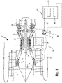
- FIG. 1 schematically represents an axial turbomachine 2. This is a turbofan engine.
- the turbojet engine 2 comprises a first compression level, called low-pressure compressor 4, a second compression level, called high-pressure compressor 6, a combustion chamber 8 and one or more levels of turbines 10.
- the mechanical power of the turbine 10 transmitted to the rotor 12 sets in motion the two compressors 4 and 6.
- the latter comprise several rows of rotor blades associated with rows of stator blades.
- the rotation of the rotor around its axis of rotation 14 thus makes it possible to generate an air flow and to gradually compress the latter until it enters the combustion chamber 8.
- An inlet fan commonly referred to as a fan or blower 16 is coupled to the rotor 12 and generates an air flow which is divided into a primary flow 18 crossing the various aforementioned levels of the turbomachine, and a secondary flow 20 crossing an annular duct (partially shown) along the machine to then join the primary flow at the turbine outlet.
- Reduction means such as a planetary gear reduction gear 22, can reduce the speed of rotation of the fan and/or of the low-pressure compressor with respect to the associated turbine.
- the secondary flow can be accelerated so as to generate a thrust reaction necessary for the flight of an aircraft.
- the primary 18 and secondary 20 streams are coaxial annular streams fitted into one another. They are channeled through the casing of the turbomachine and/or the shrouds.
- the rotor 12 comprises a transmission shaft 24 mounted on the casing by means of two bearings 26.
- FIG. 1 also very schematically shows a fuel cell 28. This enables the supply of electricity to certain engine components or to auxiliary equipment of the aircraft.
- a lubrication circuit 30 is provided.
- This circuit 30 comprises ducts 32 for transporting the oil to the components of the turbojet requiring it, such as in particular the gearbox 22 and the bearings 26.
- a heat exchanger 34 can be provided to regulate the temperature of the oil in the circuit 30.
- the exchanger 34 can be positioned in the secondary flow 20 to cool the oil.
- an exchanger 34 can also be provided downstream of the bleed valves, to heat the oil.
- valves and an appropriate control system allow the oil to pass through one of the exchangers rather than the other, in order to maintain the oil at a temperature wanted. By adapting the flow rate or the passage time in one and/or the other of the exchangers, the temperature can be regulated precisely.
- the system also comprises a hydraulic circuit 40. This makes it possible to ensure proper operation of the fuel cell 28. Ducts 42 and a heat exchanger 44 make it possible to convey the oil to the fuel cell 28.
- the two circuits 30, 40 can form only one common hydraulic circuit. Thus, the same oil can run through both circuits.
- a reservoir 60 common to the two circuits and at least one pump 50 ensure an oil flow in the two circuits.
- the two circuits 30, 40 may be separate and each comprise (at least) a pump 50 and a reservoir 60 respectively.
- circuits include all the organs making it possible to control the temperature, the pressure and the flow rate to obtain optimum operation of the fuel cell 28 and of the turbojet engine 2 (sensors, valves, booster, flow reducer, etc.) .
- the tank 60 can be fixed to the nacelle of the turbomachine 2, or to a compressor casing. It is optionally attached to an intermediate casing. Reservoir 60 can be placed between two annular walls guiding concentric flows; for example the secondary flow 20 and the flow surrounding the turbine engine 2, or between the primary flow 18 and the secondary flow 20. In order to increase its useful volume, the tank 60 is essentially elongated while following a general shape curve. This curvature allows installation between two curved and close partitions.
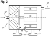
- FIG 2 schematically represents a sectional view of a known electric pump 50'.
- the pump comprises a body 51' whose walls describe a generally cylindrical shape.
- the oil is sucked in by the inlet 52' and is discharged by the outlet 53'.
- a 54' impeller (paddle wheel) rotates to suck in the oil.
- the impeller is integral with a rotor 55' driven in rotation by the electromagnetic field created by a stator 56'.
- the oil can come into contact with the turns of the stator 56' which, when they are supplied with direct current greater than a nominal operating value, give off heat. This warms the cold oil and thins it.
- the pump 50' can include all the appropriate means for its correct operation (sensors, pressure relief valves, purge valves, etc.).
- An electrical connector 57' as well as a cable 58' make it possible to supply current to the stator 56'.
- Anchoring lugs 59' are placed on the body 51' to mechanically connect the pump to the rest of the system with which it interacts.
- FIG. 3 schematically represents a sectional view of an electric pump 50 according to the invention.
- the pump comprises a body 51 whose walls describe a generally cylindrical shape.
- the oil is sucked in by the inlet 52 and is discharged by the outlet 53.
- the inlet and the outlet are represented by male connectors, projecting from the body 51 of the pump 50.
- the one, the other or both connectors 52, 53 can be of the female type.
- An impeller 54 (paddle wheel) rotates to draw in the oil.
- the impeller 54 is integral with a rotor 55 driven in rotation by the electromagnetic field created by a stator 56.
- the pump 50 can include all the appropriate means for its correct operation (sensors, pressure relief valves, purge valves, etc.).
- An electrical connector 57 and a cable 58 supply the stator 56 with current.
- the cable 58 runs through the body of the pump in a suitable housing until it reaches, or until it forms, a turn of the stator 56.
- the connector 57 may comprise a pin 571 made of a conductive material and mounted in an insulating slider 572, itself received in a cavity 573 of the body 51 of the pump 50.
- each of the pins 571 can be mounted independently and supported by a spring.
- a spring 574 and a ring 575 maintain the connector 57 in the body 51 of the pump 50 with a certain cushioning.
- the spring 574 is stiff enough so that electrical contact is maintained with the electrical outlet with which the pin 571 must cooperate, whatever the operating conditions (vibration, expansion, etc.).
- the spring can alternatively be on the module side, either to support male pins or female housings.
- Anchoring lugs 59 in the form of a single flange or several lugs spaced angularly at the periphery of the body 51 of the pump 50 make it possible to mechanically connect the pump 50 to the system with which it cooperates.
- the lugs comprise for example an orifice to receive a fastener element.
- the electrical 57, hydraulic 52, 53 and mechanical 59 connections are arranged on the same side of the body 51 of the pump 50 and in particular on the same substantially flat surface 511.
- port 53 includes a spindle 531 held in a hole 514 of body 51.
- Spindle 531 can be mounted clamped in the orifice 514 and/or may be provided with a seal 532.
- a shoulder 515 can serve as an axial stop for the spindle.
- the spindle 531 can be supported by springs, for example placed between the shoulder 515 and the spindle 531.
- picture 3 is very schematic and that a person skilled in the art would be able to adapt the teaching of the picture 2 to different types or shapes of pump.
- FIG 4 shows an external isometric view of the pump 50. It shows the flat surface 511 provided with the various elements for the electrical 57, hydraulic 52, 53 and mechanical 59 connection.
- the pump body 51 can be made in the form of a bell 512 and a cover 513, the bell 512 containing all of the functional elements of the pump 50 and the cover 513 coming to cover the bell 512 and comprising the surface plane 511.
- the module 70 can be a module directly using the fluid from the pump.
- the module can be an adapter aimed at distributing the fluid to another element.
- the module 70 can be connected on the one hand to an oil tank and on the other hand to a turbomachine compressor.
- the pump 50 and the module 70 are assembled so that the surface 511 of the pump 50 is brought into contact with a surface 711 of the module 70.
- the pump 50 includes legs 59, of which only two are visible on the figure 5 . These lugs include holes for receiving screws (not shown) which cooperate with a thread (not shown) in the module 70.
- the thread forms an example of a mechanical connection element of the module.
- a centering shoulder (not shown) or chamfers may be provided to ensure correct positioning of the pump during assembly.
- the fluid inlet 52 and outlet 53 ports in the pump 50 are placed in look of corresponding pipes 72, 73 in the module 70.
- a spindle 531 (see also picture 3 top) may be provided at the interface between the ports 52, 53 and the respective pipes 72, 73.
- Gaskets 532 can be arranged on the pump 50 side and/or on the module 70 side in order to ensure sealing.
- a flat gasket can be inserted between surface 511 and surface 711 over the entire contact zone between pump 50 and module 70.
- a female electrical socket 757 and a cable 758 are provided in the module 70 in order to ensure the electrical connection with the connector 57 of the pump 50.
- the cable 758 can be supplied with current by a battery or a current generator, possibly via other intermediate parts (not shown) which also include cables or conductors.
- the lugs 59 can be replaced by elastic L-shaped tabs, which cooperate with notches arranged on the module 70.
- Any device of the quick fastening type (“snap-fit”, bayonet) can be used.
- permanent or semi-permanent assembly means such as gluing or welding can be used.
- the pump can be provided with several inlets and/or several outlets.
- the position of the connectors on the face 511 is only given by way of example in the figures. A person skilled in the art would be able to adapt the position, type and number of connectors to his needs, to the manufacturing constraints, to the standards in force, to the nature of the fluid transported, to the type of module with which the pump interacts, etc.
- the present invention relates mainly to the electrical, hydraulic and mechanical interface between a pump and a module.
- the operation of the pump is irrelevant and those skilled in the art would recognize that several types of pump can be used without departing from the scope of protection conferred by the appended claims.
Landscapes
- Engineering & Computer Science (AREA)
- Mechanical Engineering (AREA)
- General Engineering & Computer Science (AREA)
- Structures Of Non-Positive Displacement Pumps (AREA)
Description
L'invention concerne une pompe hydraulique pour un module aéronautique tel un compresseur de turbomachine ou une pile à combustible. Plus particulièrement, l'invention concerne l'accouplement électrique, hydraulique et mécanique entre une telle pompe et un tel module.The invention relates to a hydraulic pump for an aeronautical module such as a turbomachine compressor or a fuel cell. More particularly, the invention relates to the electrical, hydraulic and mechanical coupling between such a pump and such a module.
Dans certains modules aéronautiques, un circuit de fluide parcourt le module pour réaliser des fonctions d'échange de chaleur, de lubrification ou autre. Afin de mettre en mouvement ce fluide, une pompe est agencée à proximité du module et coopère avec le circuit de fluide. La pompe peut être une pompe électrique ou peut nécessiter une alimentation électrique pour des fonctions de contrôle ou de détection notamment. Ainsi, la pompe doit être alimentée en électricité et en fluide. Le module peut parfois disposer de sa propre alimentation électrique qu'il peut partager avec la pompe. La pompe est ainsi reliée au module par un connecteur électrique et un connecteur hydraulique. Elle peut également être mécaniquement solidaire du module.In some aeronautical modules, a fluid circuit runs through the module to perform heat exchange, lubrication or other functions. In order to set this fluid in motion, a pump is arranged close to the module and cooperates with the fluid circuit. The pump may be an electric pump or may require an electrical power supply for control or detection functions in particular. Thus, the pump must be supplied with electricity and fluid. The module may sometimes have its own power supply which it may share with the pump. The pump is thus connected to the module by an electrical connector and a hydraulic connector. It can also be mechanically secured to the module.
Le document
Ce type de compresseur n'est pas adapté pour les applications aéronautiques et laisse vacante une marge d'amélioration sur la facilité de montage d'une pompe sur un module aéronautique.This type of compressor is not suitable for aeronautical applications and leaves vacant a margin of improvement on the ease of mounting a pump on an aeronautical module.
Le document
L'invention a pour objectif de résoudre au moins un des problèmes posés par l'art antérieur. Plus précisément, l'invention a pour objectif d'améliorer la facilité de montage et de connexion multifonction d'une pompe sur un module aéronautique. L'invention a également pour objectif de proposer une solution simple, résistante, économique et fiable.The object of the invention is to solve at least one of the problems posed by the prior art. More specifically, the aim of the invention is to improve the ease of assembly and multifunction connection of a pump on an aeronautical module. The invention also aims to provide a simple, resistant, economical and reliable solution.
L'invention a pour objet une pompe selon la revendication 1.The invention relates to a pump according to claim 1.
Le module peut être un sous-ensemble d'un turboréacteur comme par exemple un compresseur ou son carter, ou un réservoir. Le module peut aussi être une pile à combustible, un échangeur de chaleur, un élément du circuit d'eau ou d'air d'une cabine, etc.The module can be a subassembly of a turbojet such as for example a compressor or its casing, or a tank. The module can also be a fuel cell, a heat exchanger, an element of the water or air circuit of a cabin, etc.
Selon des modes avantageux de l'invention, la pompe peut comprendre une ou plusieurs des caractéristiques suivantes, prises isolément ou selon toutes les combinaisons techniques possibles :
- le connecteur électrique est composé de broches s'étendant perpendiculairement en saillie de la surface plane ;
- les broches sont supportées par des moyens élastiques ou amortissant, notamment des ressorts ;
- le connecteur hydraulique comprend au moins un élément mâle en saillie de la surface plane ;
- l'élément mâle est un fuseau (aussi appelé « bobine »), qui peut être ou non supporté par des moyens élastiques ou amortissant, notamment des ressorts. Alternativement, l'élément mâle peut être venu de matière avec le corps de la pompe. Alternativement, l'élément mâle est du côté du module, soit venu de matière avec le corps du module, soit formé par une pièce additionnelle, la pompe et le module présentant des éléments femelles ;
- le connecteur hydraulique comprend au moins un élément femelle niché dans la surface plane ;
- la surface plane comprend des pattes munies d'orifices formant le connecteur mécanique. Alternativement, le contour de la surface plane définit une bride qui forme le connecteur mécanique, celle-ci étant apte à coopérer, par exemple au moyen d'un collier, avec une bride du module aéronautique. Un assemblage du type V-clamp peut être utilisé ;
- le corps de la pompe est de forme sensiblement cylindrique, la surface plane formant une des bases de la forme cylindrique ;
- le corps de la pompe est composé d'un carter en forme de cloche recouverte d'un couvercle, la surface externe plane étant la surface extérieure du couvercle. Ainsi, lorsque la pompe est fixée à son module, les connexions électriques et hydrauliques sont invisibles et sont donc protégées de tout endommagement, notamment en cas de feu ;
- la pompe est une pompe hydraulique à alimentation électrique. Les fluides transportés peuvent être un fluide de refroidissement, un fluide de lubrification, un fluide d'échangeur de chaleur, etc.
- the electrical connector is composed of pins extending perpendicularly projecting from the flat surface;
- the pins are supported by elastic or damping means, in particular springs;
- the hydraulic connector comprises at least one male element projecting from the flat surface;
- the male element is a spindle (also called a “coil”), which may or may not be supported by elastic or damping means, in particular springs. Alternatively, the male element may be integral with the body of the pump. Alternatively, the male element is on the side of the module, either integral with the body of the module, or formed by an additional part, the pump and the module having female elements;
- the hydraulic connector comprises at least one female element nested in the flat surface;
- the flat surface includes lugs provided with orifices forming the mechanical connector. Alternatively, the outline of the flat surface defines a flange which forms the mechanical connector, the latter being capable of cooperating, for example by means of a collar, with a flange of the aeronautical module. A V-clamp type assembly can be used;
- the body of the pump is substantially cylindrical in shape, the flat surface forming one of the bases of the cylindrical shape;
- the body of the pump is composed of a bell-shaped casing covered with a cover, the flat outer surface being the outer surface of the cover. Thus, when the pump is attached to its module, the electrical and hydraulic connections are invisible and are therefore protected from any damage, particularly in the event of fire;
- the pump is an electrically powered hydraulic pump. The fluids transported can be coolant, lubricating fluid, heat exchanger fluid, etc.
L'invention porte également sur un module aéronautique comprenant des éléments de connexion électrique, hydraulique et mécanique, agencés de telle sorte à pouvoir coopérer avec les éléments de connexion respectifs de la pompe selon l'un des modes de réalisation exposés ci-dessus.The invention also relates to an aeronautical module comprising electrical, hydraulic and mechanical connection elements, arranged in such a way as to be able to cooperate with the respective connection elements of the pump according to one of the embodiments described above.
Selon des modes avantageux de l'invention, le module peut comprendre une ou plusieurs des caractéristiques suivantes, prises isolément ou selon toutes les combinaisons techniques possibles :
- le module se présente sous la forme d'un carter de turbomachine axiale, en particulier un carter de compresseur de turbomachine axiale ;
- le module est un réservoir ;
- le module se présente sous la forme d'une pile à combustible.
- the module is in the form of an axial turbomachine casing, in particular an axial turbomachine compressor casing;
- the module is a tank;
- the module is in the form of a fuel cell.
L'invention porte également sur un système comprenant un module selon l'un des modes de réalisation décrits ci-dessus avec une pompe selon l'un des modes de réalisation décrits ci-dessus, la pompe étant montée en connexion électrique, hydraulique et mécanique avec le module.The invention also relates to a system comprising a module according to one of the embodiments described above with a pump according to one of the embodiments described above, the pump being mounted in electrical, hydraulic and mechanical connection with the module.
L'invention porte également sur un procédé de montage d'une pompe selon l'un des modes de réalisation ci-dessus sur un module selon l'un des modes de réalisation décrits ci-dessus, le procédé comprenant une étape de mise en position de la pompe contre le module par translation selon une direction perpendiculaire à la surface plane et une étape de verrouillage de la position, notamment par des moyens de serrage tels que des vis ou un collier.The invention also relates to a method for mounting a pump according to one of the embodiments above on a module according to one of the embodiments described above, the method comprising a step of position of the pump against the module by translation in a direction perpendicular to the flat surface and a step of locking the position, in particular by clamping means such as screws or a collar.
De manière générale, les modes avantageux de chaque objet de l'invention sont également applicables aux autres objets de l'invention. Chaque objet de l'invention est combinable aux autres objets, et les objets de l'invention sont également combinables aux modes de réalisation de la description, qui en plus sont combinables entre eux, à moins que le contraire ne soit explicitement mentionné.In general, the advantageous modes of each object of the invention are also applicable to the other objects of the invention. Each object of the invention can be combined with the other objects, and the objects of the invention can also be combined with the embodiments of the description, which in addition can be combined with one another, unless the contrary is explicitly mentioned.
Le fait de prévoir, sur la même face, les connexions de plusieurs types, en l'occurrence électrique, hydraulique et mécanique, permet de faciliter grandement le montage de la pompe. Aussi, une fois la pompe montée, les connexions électriques et hydrauliques ne sont pas soumises aux conditions externes particulièrement difficiles (pression, température et oxydation, feu, etc.) qui peuvent régner dans certains environnements aéronautiques. Ainsi, le système est rendu plus fiable.The fact of providing, on the same face, the connections of several types, in this case electrical, hydraulic and mechanical, makes it possible to greatly facilitate the assembly of the pump. Also, once the pump is mounted, the electrical and hydraulic connections are not subject to the particularly difficult external conditions (pressure, temperature and oxidation, fire, etc.) which may prevail in certain aeronautical environments. Thus, the system is made more reliable.
De plus, c'est le seul verrouillage mécanique de la pompe à un module qui permet d'assurer le verrouillage électrique et hydraulique des connexions. Il n'y a donc pas de nécessité de verrouiller les connexions électriques et hydrauliques indépendamment.In addition, it is the only mechanical interlock of the one-module pump that provides electrical and hydraulic interlocking of the connections. There is therefore no need to lock the electrical and hydraulic connections independently.
-
La
figure 1 représente un système selon l'invention ;Therefigure 1 represents a system according to the invention; -
La
figure 2 décrit une vue en coupe d'une pompe électrique de l'état de la technique ;Therefigure 2 describes a sectional view of an electric pump of the state of the art; -
La
figure 3 illustre une vue en coupe d'une pompe selon l'invention ;Therepicture 3 illustrates a sectional view of a pump according to the invention; -
La
figure 4 montre une vue isométrique de la pompe selon l'invention et en particulier vue depuis la surface plane de la pompe ;Therefigure 4 shows an isometric view of the pump according to the invention and in particular seen from the flat surface of the pump; -
La
figure 5 représente une coupe transversale d'un exemple d'accouplement entre la pompe de l'invention et le module de l'invention.Therefigure 5 shows a cross section of an example of coupling between the pump of the invention and the module of the invention.
Dans la description qui va suivre, les termes « interne » et « externe » renvoient à un positionnement par rapport à l'axe de rotation d'une turbomachine axiale. La direction axiale correspond à la direction le long de l'axe de rotation de la turbomachine. La direction radiale est perpendiculaire à l'axe de rotation. L'amont et l'aval sont en référence au sens d'écoulement principal du flux dans la turbomachine. Le terme « solidaire » est compris comme solidaire en rotation. La
Un ventilateur d'entrée communément désigné fan ou soufflante 16 est couplé au rotor 12 et génère un flux d'air qui se divise en un flux primaire 18 traversant les différents niveaux susmentionnés de la turbomachine, et en un flux secondaire 20 traversant un conduit annulaire (partiellement représenté) le long de la machine pour ensuite rejoindre le flux primaire en sortie de turbine.An inlet fan commonly referred to as a fan or
Des moyens de démultiplication, tel un réducteur à train épicycloïdal 22, peuvent réduire la vitesse de rotation de la soufflante et/ou du compresseur basse-pression par rapport à la turbine associée. Le flux secondaire peut être accéléré de sorte à générer une réaction de poussée nécessaire au vol d'un avion. Les flux primaire 18 et secondaire 20 sont des flux annulaires coaxiaux et emmanchés l'un dans l'autre. Ils sont canalisés par le carter de la turbomachine et/ou des viroles.Reduction means, such as a planetary
Le rotor 12 comprend un arbre de transmission 24 monté sur le carter au moyen de deux paliers 26.The
La
Afin de lubrifier les éléments tournants du turboréacteur 2, un circuit de lubrification 30 est prévu. Ce circuit 30 comprend des conduits 32 pour transporter l'huile aux organes du turboréacteur la nécessitant, comme notamment la boite d'engrenage 22 et les paliers 26. Un échangeur à chaleur 34 peut être prévu pour réguler la température de l'huile dans le circuit 30. L'échangeur 34 peut être positionné dans le flux secondaire 20 pour refroidir l'huile. Alternativement, ou en complément, un échangeur 34 peut aussi être prévu en aval des vannes de bleed, pour réchauffer l'huile. Lorsque les deux types d'échangeur (froid et chaud) sont prévus, des vannes et un système de contrôle adéquat permettent de faire passer l'huile plutôt dans un des échangeurs que dans l'autre, afin de maintenir l'huile à une température voulue. En adaptant le débit ou le temps de passage dans l'un et/ou l'autre des échangeurs, la température peut être régulée de manière précise.In order to lubricate the rotating elements of the
Le système comprend également un circuit hydraulique 40. Celui-ci permet d'assurer un bon fonctionnement de la pile à combustible 28. Des conduits 42 et un échangeur à chaleur 44 permettent de convoyer l'huile jusqu'à la pile à combustible 28.The system also comprises a
Les deux circuits 30, 40 peuvent ne former qu'un seul circuit hydraulique commun. Ainsi, une même huile peut parcourir les deux circuits. Un réservoir 60 commun aux deux circuits et au moins une pompe 50 viennent assurer un débit d'huile dans les deux circuits.The two
Alternativement, les deux circuits 30, 40 peuvent être distincts et comporter chacun (au moins) une pompe 50 et un réservoir 60 respectifs.Alternatively, the two
Il est entendu que les circuits comprennent tous les organes permettant de contrôler la température, la pression et le débit pour obtenir un fonctionnement optimal de la pile à combustible 28 et du turboréacteur 2 (capteurs, vannes, surpresseur, réducteur de débit, etc.).It is understood that the circuits include all the organs making it possible to control the temperature, the pressure and the flow rate to obtain optimum operation of the
Le réservoir 60 peut être fixé à la nacelle de la turbomachine 2, ou à un carter de compresseur. Il est optionnellement fixé à un carter intermédiaire. Le réservoir 60 peut être placé entre deux parois annulaires guidant des flux concentriques ; par exemple le flux secondaire 20 et le flux entourant la turbomachine 2, ou entre le flux primaire 18 et le flux secondaire 20. Afin d'augmenter son volume utile, le réservoir 60 est essentiellement allongé tout en suivant une forme générale courbe. Cette courbure permet une implantation entre deux cloisons courbes et rapprochées.The
La
L'huile peut venir au contact des spires du stator 56' qui, lorsqu'elles sont alimentées en courant continu supérieur à une valeur nominale de fonctionnement, dégagent de la chaleur. Ceci permet de réchauffer l'huile froide et de la fluidifier.The oil can come into contact with the turns of the stator 56' which, when they are supplied with direct current greater than a nominal operating value, give off heat. This warms the cold oil and thins it.
La pompe 50' peut comprendre tous les moyens appropriés à son bon fonctionnement (capteurs, vannes de surpression, de purge, etc.).The pump 50' can include all the appropriate means for its correct operation (sensors, pressure relief valves, purge valves, etc.).
Un connecteur électrique 57' ainsi qu'un câble 58' permettent d'alimenter le stator 56' en courant.An electrical connector 57' as well as a cable 58' make it possible to supply current to the stator 56'.
Des pattes d'ancrage 59' sont disposées sur le corps 51' pour connecter mécaniquement la pompe au reste du système avec lequel elle interagit.Anchoring lugs 59' are placed on the body 51' to mechanically connect the pump to the rest of the system with which it interacts.
Sur cet exemple de pompe, les connexions électrique (57'), hydraulique (52', 53') et mécanique (59') sont agencées à différents endroits de la pompe. Lors du montage de la pompe 50' dans le système, il est donc nécessaire d'effectuer indépendamment les opérations relatives à chacun de ces types de connexion. La
La pompe 50 peut comprendre tous les moyens appropriés à son bon fonctionnement (capteurs, vannes de surpression, de purge, etc.).The
Un connecteur électrique 57 ainsi qu'un câble 58 permettent d'alimenter le stator 56 en courant. Le câble 58 chemine dans le corps de la pompe dans un logement approprié jusqu'à atteindre, ou jusqu'à former, une spire du stator 56. Sur une partie agrandie de la
Des pattes d'ancrage 59 sous forme d'une bride unique ou de plusieurs pattes espacées angulairement à la périphérie du corps 51 de pompe 50 permettent de connecter mécaniquement la pompe 50 au système avec lequel elle coopère. Les pattes comprennent par exemple un orifice pour recevoir un élément de visserie.Anchoring lugs 59 in the form of a single flange or several lugs spaced angularly at the periphery of the
Sur cet exemple de pompe selon l'invention, les connexions électrique 57, hydraulique 52, 53 et mécanique 59 sont agencées sur le même côté du corps 51 de pompe 50 et en particulier sur une même surface, sensiblement plane, 511.In this example of a pump according to the invention, the electrical 57, hydraulic 52, 53 and mechanical 59 connections are arranged on the same side of the
Lors du montage de la pompe 50 dans un système, il est donc possible d'effectuer les opérations de connexion relatives à chacun de ces types de connexion simultanément. C'est d'ailleurs le verrouillage de la connexion mécanique qui verrouille simultanément les autres types de connexion.When mounting the
Sur une vue partielle agrandie de la
Il est à noter que la
La
Le corps de pompe 51 peut être réalisé sous la forme d'une cloche 512 et d'un couvercle 513, la cloche 512 renfermant l'intégralité des éléments fonctionnels de la pompe 50 et le couvercle 513 venant recouvrir la cloche 512 et comprenant la surface plane 511. Ainsi, une fois montée sur le module (voir
La pompe 50 et le module 70 sont assemblés de sorte à ce que la surface 511 de la pompe 50 soit mise au contact d'une surface 711 du module 70.The
La pompe 50 comprend des pattes 59, dont seules deux sont visibles sur la
Les ports d'entrée 52 et de sortie 53 du fluide dans la pompe 50 sont mis en regard de canalisations 72, 73 correspondantes dans le module 70. Un fuseau 531 (voir aussi
Optionnellement, un joint plat peut être intercalé entre la surface 511 et la surface 711 sur toute la zone de contact entre la pompe 50 et le module 70.Optionally, a flat gasket can be inserted between
Une prise électrique femelle 757 et un câble 758 sont prévus dans le module 70 afin d'assurer la connexion électrique avec le connecteur 57 de la pompe 50. Le câble 758 peut être alimenté en courant par une batterie ou un générateur de courant, éventuellement via d'autres pièces intermédiaires (non représentées) qui comportent également des câbles ou des conducteurs.A female
Les figures n'illustrent que des exemples possibles de réalisation de l'invention. D'autres formes de réalisation de l'invention sont possibles.The figures only illustrate possible embodiments of the invention. Other embodiments of the invention are possible.
Par exemple, les pattes 59 peuvent être remplacées par des languettes en forme de L, élastiques, qui coopèrent avec des encoches agencées sur le module 70. Tout dispositif du type fixation rapide (« snap-fit », baïonnette) peut être utilisé. Aussi, des moyens d'assemblage permanents ou semi-permanents tel que le collage ou le soudage peuvent être employés.For example, the
La pompe peut être pourvue de plusieurs entrées et/ou plusieurs sorties. La position des connecteurs sur la face 511 n'est donnée qu'à titre d'exemple sur les figures. L'homme du métier saurait adapter la position, le type et le nombre de connecteurs à ses besoins, aux contraintes de fabrication, aux normes en vigueur, à la nature du fluide transporté, au type de module avec lequel la pompe interagit, etc.The pump can be provided with several inlets and/or several outlets. The position of the connectors on the
La présente invention porte principalement sur l'interface électrique, hydraulique et mécanique entre une pompe et un module. Le fonctionnement de la pompe est indifférent et l'homme du métier reconnaîtrait que plusieurs types de pompe peuvent être utilisés sans s'éloigner de l'étendue de protection conférée par les revendications attenantes.The present invention relates mainly to the electrical, hydraulic and mechanical interface between a pump and a module. The operation of the pump is irrelevant and those skilled in the art would recognize that several types of pump can be used without departing from the scope of protection conferred by the appended claims.
Claims (14)
- Pump (50) for an aeronautical module (70), the pump (50) comprising a body (51) having at least one substantially flat outer surface (511), the pump including an electrical connector (57), a hydraulic connector (52, 53) and a mechanical connector (59) for electrical, hydraulic and mechanical connection of the pump (50) to the aeronautical module (70),
wherein the connectors (52, 53, 57, 59) are all arranged on its flat surface (511), and wherein the hydraulic connector (52, 53) is comprised of at least one fluid inlet port (52) for the entry of fluid into the body (51) and at least one fluid outlet port (53) for the exit of fluid from the body (51). - Pump (50) according to claim 1, wherein the electrical connector (57) is composed of pins (571) extending perpendicularly from the flat surface (511).
- Pump (50) according to claim 1 or 2, wherein the pins (571) are supported by elastic means (574) or damping means, in particular springs.
- Pump (50) according to any one of claims 1 to 3, wherein the hydraulic connector (52, 53) comprises at least one male element (52, 53) protruding from the flat surface (511).
- Pump (50) according to claim 4, wherein the male element (52, 53) is a spindle (531), preferably supported by elastic or damping means, in particular springs.
- Pump (50) according to any one of claims 1 to 5, wherein the hydraulic connector (52, 53) comprises at least one female element embedded in the flat surface (511).
- Pump (50) according to any one of claims 1 to 6, wherein the flat surface (511) includes lugs (59) provided with holes (591) forming the mechanical connector (59).
- Pump (50) according to any one of claims 1 to 7, wherein the contour of the flat surface (511) defines a flange that forms the mechanical connector (59), the latter being adapted to cooperate, for example by means of a collar, with a flange of the aeronautical module.
- Pump (50) according to any one of claims 1 to 8, wherein the body (51) of the pump (50) is substantially cylindrical in shape, the flat surface (511) forming one of the bases of the cylindrical shape.
- Pump (50) according to any one of claims 1 to 9, wherein the body (51) of the pump (50) is composed of a bell (512) covered with a lid (513), the flat outer surface (511) being the outer surface of the lid (513).
- Pump (50) according to any one of claims 1 to 10, the pump being an electric powered hydraulic pump (50).
- An aeronautical module (70) comprising electrical (757), hydraulic (72, 73) and mechanical connection elements, arranged so as to be able to cooperate with the respective connection elements (52, 53, 57, 59) of the pump (50) according to any of claims 1 to 11, the module being optionally constructed in the form of a compressor housing (4, 6) of an axial turbomachine (2) or in the form of a fuel cell (28).
- System comprising a module (70) according to claim 12 and a pump (50) according to any of claims 1 to 11 mounted in electrical, hydraulic and mechanical connection with said module (70).
- Method for mounting a pump (50) according to any of claims 1 to 11 on a module (70) according to claim 12, the method comprising:positioning the pump (50) against the module (70) by translation in a direction (A) perpendicular to the flat surface (511) andsecuring in the desired position, in particular by clamping means such as screws.
Applications Claiming Priority (1)
| Application Number | Priority Date | Filing Date | Title |
|---|---|---|---|
| BE20185608A BE1026581B1 (en) | 2018-08-31 | 2018-08-31 | TURBOMACHINE PUMP |
Publications (2)
| Publication Number | Publication Date |
|---|---|
| EP3617518A1 EP3617518A1 (en) | 2020-03-04 |
| EP3617518B1 true EP3617518B1 (en) | 2023-03-22 |
Family
ID=63713571
Family Applications (1)
| Application Number | Title | Priority Date | Filing Date |
|---|---|---|---|
| EP19193885.1A Active EP3617518B1 (en) | 2018-08-31 | 2019-08-27 | Pump of turbomachine |
Country Status (2)
| Country | Link |
|---|---|
| EP (1) | EP3617518B1 (en) |
| BE (1) | BE1026581B1 (en) |
Family Cites Families (11)
| Publication number | Priority date | Publication date | Assignee | Title |
|---|---|---|---|---|
| JPS59110896A (en) * | 1982-12-15 | 1984-06-26 | Ebara Corp | Submersible motor pump |
| JPH07109975A (en) | 1993-10-15 | 1995-04-25 | Sawafuji Electric Co Ltd | Vibration type compressor |
| US6436287B1 (en) * | 2000-12-20 | 2002-08-20 | Robert Bosch Corportion | Fuel pump module and method for installing the same |
| KR20110067240A (en) * | 2009-12-14 | 2011-06-22 | 주식회사 코아비스 | A bldc fuel pump module equipped in one with driver |
| US9181902B2 (en) * | 2010-11-17 | 2015-11-10 | Aisan Kogyo Kabushiki Kaisha | Fuel tank and method for producing same |
| US9360015B2 (en) * | 2012-07-16 | 2016-06-07 | Magna Powertrain Of America, Inc. | Submerged rotor electric water pump with structural wetsleeve |
| KR101222010B1 (en) * | 2012-10-31 | 2013-02-08 | 주식회사 코아비스 | Fuel pump module |
| JP5929876B2 (en) * | 2013-11-12 | 2016-06-08 | 株式会社デンソー | Drive control device and fuel pump using the same |
| JP6258158B2 (en) * | 2014-08-26 | 2018-01-10 | 愛三工業株式会社 | Fuel supply device |
| DE102015114783B3 (en) * | 2015-09-03 | 2016-09-22 | Nidec Gpm Gmbh | Electric coolant pump with flow-cooled control circuit |
| FR3060671B1 (en) * | 2016-12-16 | 2021-01-22 | Wilo Intec | FLUID CIRCULATION PUMP |
-
2018
- 2018-08-31 BE BE20185608A patent/BE1026581B1/en active IP Right Grant
-
2019
- 2019-08-27 EP EP19193885.1A patent/EP3617518B1/en active Active
Also Published As
| Publication number | Publication date |
|---|---|
| BE1026581B1 (en) | 2020-03-31 |
| BE1026581A1 (en) | 2020-03-24 |
| EP3617518A1 (en) | 2020-03-04 |
Similar Documents
| Publication | Publication Date | Title |
|---|---|---|
| EP1953899B1 (en) | Assembly of gear box and starter-generator for a gas turbine | |
| EP3870810B1 (en) | Fan module equipped with an electrical machine for a turbomachine of an aircraft | |
| EP1662636A2 (en) | Turbomachine with an integrated electrical generator | |
| EP2591219A1 (en) | Method and architecture for recombining the power of a turbomachine | |
| FR3087820A1 (en) | AIRCRAFT TURBOMACHINE EQUIPPED WITH AN ELECTRIC MACHINE | |
| FR3046199A1 (en) | TURBOMACHINE COMPRISING A SURFACIAL AIR-OIL EXCHANGER INTEGRATED WITH AN INTER-VEIN COMPARTMENT | |
| EP3698050A1 (en) | Outer turbocharger housing having an integrated oil tank | |
| FR3046200B1 (en) | TURBOMACHINE COMPRISING AN OIL TANK AND AN AIR-OIL EXCHANGER | |
| EP3617518B1 (en) | Pump of turbomachine | |
| FR2946091A1 (en) | Ducted-fan turbine engine i.e. jet engine, for aircraft, has generator whose input shaft axis is inclined with respect to longitudinal axis of engine, so as to radially deviate shaft axis outside from engine while moving generator backward | |
| EP3870811B1 (en) | Turbomachine with an electrical machine having a rotor ring adjacent to the fan | |
| EP4073367A1 (en) | Auxiliary power unit comprising a gas generator in direct-drive connection with an electric generator, and an accessories housing | |
| FR3093530A1 (en) | Turbomachine comprising a heat exchanger formed in a platform | |
| EP4077887B1 (en) | Turbogenerator for aircraft, comprising an improved oil system | |
| US20080276893A1 (en) | Single piece rotor | |
| EP3862551A1 (en) | Accessories relay housing for a turbine engine | |
| EP3899240B1 (en) | Fuel supply device | |
| FR3061241A1 (en) | REVERSE FLOW TURBOPROPULSER | |
| FR3129982A1 (en) | Service arm for an exhaust casing of a turbomachine | |
| FR3108932A1 (en) | VENTILATION DEVICE FOR A TURBOMACHINE STATOR CASE | |
| WO2024153876A1 (en) | Assembly comprising an accessory gearbox and a lubrication unit | |
| FR3086690A1 (en) | AIRCRAFT CONFIGURED AS A CURRENT GENERATOR, EQUIPMENT AND KIT FOR SUCH AN AIRCRAFT AND METHOD FOR EQUIPMENT OF AN AIRCRAFT | |
| WO2024189295A1 (en) | Intermediate casing for a turbine engine | |
| WO2021181028A1 (en) | Speed reducer equipped with an electric machine |
Legal Events
| Date | Code | Title | Description |
|---|---|---|---|
| PUAI | Public reference made under article 153(3) epc to a published international application that has entered the european phase |
Free format text: ORIGINAL CODE: 0009012 |
|
| STAA | Information on the status of an ep patent application or granted ep patent |
Free format text: STATUS: THE APPLICATION HAS BEEN PUBLISHED |
|
| AK | Designated contracting states |
Kind code of ref document: A1 Designated state(s): AL AT BE BG CH CY CZ DE DK EE ES FI FR GB GR HR HU IE IS IT LI LT LU LV MC MK MT NL NO PL PT RO RS SE SI SK SM TR |
|
| AX | Request for extension of the european patent |
Extension state: BA ME |
|
| STAA | Information on the status of an ep patent application or granted ep patent |
Free format text: STATUS: REQUEST FOR EXAMINATION WAS MADE |
|
| 17P | Request for examination filed |
Effective date: 20200814 |
|
| RBV | Designated contracting states (corrected) |
Designated state(s): AL AT BE BG CH CY CZ DE DK EE ES FI FR GB GR HR HU IE IS IT LI LT LU LV MC MK MT NL NO PL PT RO RS SE SI SK SM TR |
|
| GRAP | Despatch of communication of intention to grant a patent |
Free format text: ORIGINAL CODE: EPIDOSNIGR1 |
|
| STAA | Information on the status of an ep patent application or granted ep patent |
Free format text: STATUS: GRANT OF PATENT IS INTENDED |
|
| INTG | Intention to grant announced |
Effective date: 20220907 |
|
| GRAJ | Information related to disapproval of communication of intention to grant by the applicant or resumption of examination proceedings by the epo deleted |
Free format text: ORIGINAL CODE: EPIDOSDIGR1 |
|
| STAA | Information on the status of an ep patent application or granted ep patent |
Free format text: STATUS: REQUEST FOR EXAMINATION WAS MADE |
|
| GRAP | Despatch of communication of intention to grant a patent |
Free format text: ORIGINAL CODE: EPIDOSNIGR1 |
|
| STAA | Information on the status of an ep patent application or granted ep patent |
Free format text: STATUS: GRANT OF PATENT IS INTENDED |
|
| GRAS | Grant fee paid |
Free format text: ORIGINAL CODE: EPIDOSNIGR3 |
|
| INTC | Intention to grant announced (deleted) | ||
| GRAA | (expected) grant |
Free format text: ORIGINAL CODE: 0009210 |
|
| STAA | Information on the status of an ep patent application or granted ep patent |
Free format text: STATUS: THE PATENT HAS BEEN GRANTED |
|
| INTG | Intention to grant announced |
Effective date: 20230206 |
|
| AK | Designated contracting states |
Kind code of ref document: B1 Designated state(s): AL AT BE BG CH CY CZ DE DK EE ES FI FR GB GR HR HU IE IS IT LI LT LU LV MC MK MT NL NO PL PT RO RS SE SI SK SM TR |
|
| REG | Reference to a national code |
Ref country code: GB Ref legal event code: FG4D Free format text: NOT ENGLISH |
|
| REG | Reference to a national code |
Ref country code: CH Ref legal event code: EP |
|
| REG | Reference to a national code |
Ref country code: DE Ref legal event code: R096 Ref document number: 602019026583 Country of ref document: DE |
|
| REG | Reference to a national code |
Ref country code: IE Ref legal event code: FG4D Free format text: LANGUAGE OF EP DOCUMENT: FRENCH |
|
| REG | Reference to a national code |
Ref country code: AT Ref legal event code: REF Ref document number: 1555450 Country of ref document: AT Kind code of ref document: T Effective date: 20230415 |
|
| REG | Reference to a national code |
Ref country code: LT Ref legal event code: MG9D |
|
| REG | Reference to a national code |
Ref country code: NL Ref legal event code: MP Effective date: 20230322 |
|
| PG25 | Lapsed in a contracting state [announced via postgrant information from national office to epo] |
Ref country code: RS Free format text: LAPSE BECAUSE OF FAILURE TO SUBMIT A TRANSLATION OF THE DESCRIPTION OR TO PAY THE FEE WITHIN THE PRESCRIBED TIME-LIMIT Effective date: 20230322 Ref country code: NO Free format text: LAPSE BECAUSE OF FAILURE TO SUBMIT A TRANSLATION OF THE DESCRIPTION OR TO PAY THE FEE WITHIN THE PRESCRIBED TIME-LIMIT Effective date: 20230622 Ref country code: LV Free format text: LAPSE BECAUSE OF FAILURE TO SUBMIT A TRANSLATION OF THE DESCRIPTION OR TO PAY THE FEE WITHIN THE PRESCRIBED TIME-LIMIT Effective date: 20230322 Ref country code: LT Free format text: LAPSE BECAUSE OF FAILURE TO SUBMIT A TRANSLATION OF THE DESCRIPTION OR TO PAY THE FEE WITHIN THE PRESCRIBED TIME-LIMIT Effective date: 20230322 Ref country code: HR Free format text: LAPSE BECAUSE OF FAILURE TO SUBMIT A TRANSLATION OF THE DESCRIPTION OR TO PAY THE FEE WITHIN THE PRESCRIBED TIME-LIMIT Effective date: 20230322 |
|
| REG | Reference to a national code |
Ref country code: AT Ref legal event code: MK05 Ref document number: 1555450 Country of ref document: AT Kind code of ref document: T Effective date: 20230322 |
|
| PG25 | Lapsed in a contracting state [announced via postgrant information from national office to epo] |
Ref country code: SE Free format text: LAPSE BECAUSE OF FAILURE TO SUBMIT A TRANSLATION OF THE DESCRIPTION OR TO PAY THE FEE WITHIN THE PRESCRIBED TIME-LIMIT Effective date: 20230322 Ref country code: NL Free format text: LAPSE BECAUSE OF FAILURE TO SUBMIT A TRANSLATION OF THE DESCRIPTION OR TO PAY THE FEE WITHIN THE PRESCRIBED TIME-LIMIT Effective date: 20230322 Ref country code: GR Free format text: LAPSE BECAUSE OF FAILURE TO SUBMIT A TRANSLATION OF THE DESCRIPTION OR TO PAY THE FEE WITHIN THE PRESCRIBED TIME-LIMIT Effective date: 20230623 Ref country code: FI Free format text: LAPSE BECAUSE OF FAILURE TO SUBMIT A TRANSLATION OF THE DESCRIPTION OR TO PAY THE FEE WITHIN THE PRESCRIBED TIME-LIMIT Effective date: 20230322 |
|
| PG25 | Lapsed in a contracting state [announced via postgrant information from national office to epo] |
Ref country code: SM Free format text: LAPSE BECAUSE OF FAILURE TO SUBMIT A TRANSLATION OF THE DESCRIPTION OR TO PAY THE FEE WITHIN THE PRESCRIBED TIME-LIMIT Effective date: 20230322 Ref country code: RO Free format text: LAPSE BECAUSE OF FAILURE TO SUBMIT A TRANSLATION OF THE DESCRIPTION OR TO PAY THE FEE WITHIN THE PRESCRIBED TIME-LIMIT Effective date: 20230322 Ref country code: PT Free format text: LAPSE BECAUSE OF FAILURE TO SUBMIT A TRANSLATION OF THE DESCRIPTION OR TO PAY THE FEE WITHIN THE PRESCRIBED TIME-LIMIT Effective date: 20230724 Ref country code: ES Free format text: LAPSE BECAUSE OF FAILURE TO SUBMIT A TRANSLATION OF THE DESCRIPTION OR TO PAY THE FEE WITHIN THE PRESCRIBED TIME-LIMIT Effective date: 20230322 Ref country code: EE Free format text: LAPSE BECAUSE OF FAILURE TO SUBMIT A TRANSLATION OF THE DESCRIPTION OR TO PAY THE FEE WITHIN THE PRESCRIBED TIME-LIMIT Effective date: 20230322 Ref country code: AT Free format text: LAPSE BECAUSE OF FAILURE TO SUBMIT A TRANSLATION OF THE DESCRIPTION OR TO PAY THE FEE WITHIN THE PRESCRIBED TIME-LIMIT Effective date: 20230322 |
|
| PGFP | Annual fee paid to national office [announced via postgrant information from national office to epo] |
Ref country code: GB Payment date: 20230720 Year of fee payment: 5 |
|
| PG25 | Lapsed in a contracting state [announced via postgrant information from national office to epo] |
Ref country code: SK Free format text: LAPSE BECAUSE OF FAILURE TO SUBMIT A TRANSLATION OF THE DESCRIPTION OR TO PAY THE FEE WITHIN THE PRESCRIBED TIME-LIMIT Effective date: 20230322 Ref country code: PL Free format text: LAPSE BECAUSE OF FAILURE TO SUBMIT A TRANSLATION OF THE DESCRIPTION OR TO PAY THE FEE WITHIN THE PRESCRIBED TIME-LIMIT Effective date: 20230322 Ref country code: IS Free format text: LAPSE BECAUSE OF FAILURE TO SUBMIT A TRANSLATION OF THE DESCRIPTION OR TO PAY THE FEE WITHIN THE PRESCRIBED TIME-LIMIT Effective date: 20230722 |
|
| PGFP | Annual fee paid to national office [announced via postgrant information from national office to epo] |
Ref country code: FR Payment date: 20230720 Year of fee payment: 5 Ref country code: DE Payment date: 20230720 Year of fee payment: 5 Ref country code: BE Payment date: 20230720 Year of fee payment: 5 |
|
| REG | Reference to a national code |
Ref country code: DE Ref legal event code: R097 Ref document number: 602019026583 Country of ref document: DE |
|
| PLBE | No opposition filed within time limit |
Free format text: ORIGINAL CODE: 0009261 |
|
| STAA | Information on the status of an ep patent application or granted ep patent |
Free format text: STATUS: NO OPPOSITION FILED WITHIN TIME LIMIT |
|
| PG25 | Lapsed in a contracting state [announced via postgrant information from national office to epo] |
Ref country code: SI Free format text: LAPSE BECAUSE OF FAILURE TO SUBMIT A TRANSLATION OF THE DESCRIPTION OR TO PAY THE FEE WITHIN THE PRESCRIBED TIME-LIMIT Effective date: 20230322 Ref country code: DK Free format text: LAPSE BECAUSE OF FAILURE TO SUBMIT A TRANSLATION OF THE DESCRIPTION OR TO PAY THE FEE WITHIN THE PRESCRIBED TIME-LIMIT Effective date: 20230322 Ref country code: CZ Free format text: LAPSE BECAUSE OF FAILURE TO SUBMIT A TRANSLATION OF THE DESCRIPTION OR TO PAY THE FEE WITHIN THE PRESCRIBED TIME-LIMIT Effective date: 20230322 |
|
| 26N | No opposition filed |
Effective date: 20240102 |
|
| PG25 | Lapsed in a contracting state [announced via postgrant information from national office to epo] |
Ref country code: MC Free format text: LAPSE BECAUSE OF FAILURE TO SUBMIT A TRANSLATION OF THE DESCRIPTION OR TO PAY THE FEE WITHIN THE PRESCRIBED TIME-LIMIT Effective date: 20230322 |
|
| REG | Reference to a national code |
Ref country code: CH Ref legal event code: PL |
|
| PG25 | Lapsed in a contracting state [announced via postgrant information from national office to epo] |
Ref country code: MC Free format text: LAPSE BECAUSE OF FAILURE TO SUBMIT A TRANSLATION OF THE DESCRIPTION OR TO PAY THE FEE WITHIN THE PRESCRIBED TIME-LIMIT Effective date: 20230322 |
|
| PG25 | Lapsed in a contracting state [announced via postgrant information from national office to epo] |
Ref country code: LU Free format text: LAPSE BECAUSE OF NON-PAYMENT OF DUE FEES Effective date: 20230827 |
|
| PG25 | Lapsed in a contracting state [announced via postgrant information from national office to epo] |
Ref country code: LU Free format text: LAPSE BECAUSE OF NON-PAYMENT OF DUE FEES Effective date: 20230827 Ref country code: CH Free format text: LAPSE BECAUSE OF NON-PAYMENT OF DUE FEES Effective date: 20230831 |
|
| REG | Reference to a national code |
Ref country code: IE Ref legal event code: MM4A |
|
| PG25 | Lapsed in a contracting state [announced via postgrant information from national office to epo] |
Ref country code: IT Free format text: LAPSE BECAUSE OF FAILURE TO SUBMIT A TRANSLATION OF THE DESCRIPTION OR TO PAY THE FEE WITHIN THE PRESCRIBED TIME-LIMIT Effective date: 20230322 |
|
| PG25 | Lapsed in a contracting state [announced via postgrant information from national office to epo] |
Ref country code: IE Free format text: LAPSE BECAUSE OF NON-PAYMENT OF DUE FEES Effective date: 20230827 |
|
| PG25 | Lapsed in a contracting state [announced via postgrant information from national office to epo] |
Ref country code: IE Free format text: LAPSE BECAUSE OF NON-PAYMENT OF DUE FEES Effective date: 20230827 |