EP3617516A1 - Screw compressor, air conditioning device and refrigerating device - Google Patents
Screw compressor, air conditioning device and refrigerating device Download PDFInfo
- Publication number
- EP3617516A1 EP3617516A1 EP17907068.5A EP17907068A EP3617516A1 EP 3617516 A1 EP3617516 A1 EP 3617516A1 EP 17907068 A EP17907068 A EP 17907068A EP 3617516 A1 EP3617516 A1 EP 3617516A1
- Authority
- EP
- European Patent Office
- Prior art keywords
- gas
- supplement
- screw compressor
- holes
- channel
- Prior art date
- Legal status (The legal status is an assumption and is not a legal conclusion. Google has not performed a legal analysis and makes no representation as to the accuracy of the status listed.)
- Granted
Links
Images

Classifications
-
- F—MECHANICAL ENGINEERING; LIGHTING; HEATING; WEAPONS; BLASTING
- F04—POSITIVE - DISPLACEMENT MACHINES FOR LIQUIDS; PUMPS FOR LIQUIDS OR ELASTIC FLUIDS
- F04C—ROTARY-PISTON, OR OSCILLATING-PISTON, POSITIVE-DISPLACEMENT MACHINES FOR LIQUIDS; ROTARY-PISTON, OR OSCILLATING-PISTON, POSITIVE-DISPLACEMENT PUMPS
- F04C18/00—Rotary-piston pumps specially adapted for elastic fluids
- F04C18/08—Rotary-piston pumps specially adapted for elastic fluids of intermeshing-engagement type, i.e. with engagement of co-operating members similar to that of toothed gearing
- F04C18/12—Rotary-piston pumps specially adapted for elastic fluids of intermeshing-engagement type, i.e. with engagement of co-operating members similar to that of toothed gearing of other than internal-axis type
- F04C18/14—Rotary-piston pumps specially adapted for elastic fluids of intermeshing-engagement type, i.e. with engagement of co-operating members similar to that of toothed gearing of other than internal-axis type with toothed rotary pistons
- F04C18/16—Rotary-piston pumps specially adapted for elastic fluids of intermeshing-engagement type, i.e. with engagement of co-operating members similar to that of toothed gearing of other than internal-axis type with toothed rotary pistons with helical teeth, e.g. chevron-shaped, screw type
-
- F—MECHANICAL ENGINEERING; LIGHTING; HEATING; WEAPONS; BLASTING
- F04—POSITIVE - DISPLACEMENT MACHINES FOR LIQUIDS; PUMPS FOR LIQUIDS OR ELASTIC FLUIDS
- F04C—ROTARY-PISTON, OR OSCILLATING-PISTON, POSITIVE-DISPLACEMENT MACHINES FOR LIQUIDS; ROTARY-PISTON, OR OSCILLATING-PISTON, POSITIVE-DISPLACEMENT PUMPS
- F04C29/00—Component parts, details or accessories of pumps or pumping installations, not provided for in groups F04C18/00 - F04C28/00
- F04C29/06—Silencing
-
- F—MECHANICAL ENGINEERING; LIGHTING; HEATING; WEAPONS; BLASTING
- F04—POSITIVE - DISPLACEMENT MACHINES FOR LIQUIDS; PUMPS FOR LIQUIDS OR ELASTIC FLUIDS
- F04C—ROTARY-PISTON, OR OSCILLATING-PISTON, POSITIVE-DISPLACEMENT MACHINES FOR LIQUIDS; ROTARY-PISTON, OR OSCILLATING-PISTON, POSITIVE-DISPLACEMENT PUMPS
- F04C2240/00—Components
- F04C2240/30—Casings or housings
-
- F—MECHANICAL ENGINEERING; LIGHTING; HEATING; WEAPONS; BLASTING
- F04—POSITIVE - DISPLACEMENT MACHINES FOR LIQUIDS; PUMPS FOR LIQUIDS OR ELASTIC FLUIDS
- F04C—ROTARY-PISTON, OR OSCILLATING-PISTON, POSITIVE-DISPLACEMENT MACHINES FOR LIQUIDS; ROTARY-PISTON, OR OSCILLATING-PISTON, POSITIVE-DISPLACEMENT PUMPS
- F04C2250/00—Geometry
- F04C2250/10—Geometry of the inlet or outlet
-
- F—MECHANICAL ENGINEERING; LIGHTING; HEATING; WEAPONS; BLASTING
- F04—POSITIVE - DISPLACEMENT MACHINES FOR LIQUIDS; PUMPS FOR LIQUIDS OR ELASTIC FLUIDS
- F04C—ROTARY-PISTON, OR OSCILLATING-PISTON, POSITIVE-DISPLACEMENT MACHINES FOR LIQUIDS; ROTARY-PISTON, OR OSCILLATING-PISTON, POSITIVE-DISPLACEMENT PUMPS
- F04C2250/00—Geometry
- F04C2250/10—Geometry of the inlet or outlet
- F04C2250/101—Geometry of the inlet or outlet of the inlet
-
- F—MECHANICAL ENGINEERING; LIGHTING; HEATING; WEAPONS; BLASTING
- F04—POSITIVE - DISPLACEMENT MACHINES FOR LIQUIDS; PUMPS FOR LIQUIDS OR ELASTIC FLUIDS
- F04C—ROTARY-PISTON, OR OSCILLATING-PISTON, POSITIVE-DISPLACEMENT MACHINES FOR LIQUIDS; ROTARY-PISTON, OR OSCILLATING-PISTON, POSITIVE-DISPLACEMENT PUMPS
- F04C29/00—Component parts, details or accessories of pumps or pumping installations, not provided for in groups F04C18/00 - F04C28/00
- F04C29/12—Arrangements for admission or discharge of the working fluid, e.g. constructional features of the inlet or outlet
-
- F—MECHANICAL ENGINEERING; LIGHTING; HEATING; WEAPONS; BLASTING
- F24—HEATING; RANGES; VENTILATING
- F24F—AIR-CONDITIONING; AIR-HUMIDIFICATION; VENTILATION; USE OF AIR CURRENTS FOR SCREENING
- F24F13/00—Details common to, or for air-conditioning, air-humidification, ventilation or use of air currents for screening
- F24F13/24—Means for preventing or suppressing noise
Definitions
- the present disclosure relates to the field of compressor technology, and particularly to a screw compressor, an air conditioning apparatus and a refrigeration apparatus including the screw compressor.
- the screw compressor generally includes a body and a couple of parallel and mutual engaged female and male screws provided in the body.
- a gas intake is provided in the body corresponding to one end of the female screw and one end of the male screw, and an exhaust port is provided in the body corresponding to the other end of the female screw and the other end of the male screw.
- the screw compressor compresses the low-temperature and low-pressure gas entering from the gas intake of the body into high-temperature and high-pressure gas, and discharges the high-temperature and high-pressure gas from the exhaust port of the body through the rotation of the female and male screws in opposite directions to each other.
- the body of the existing screw compressor is usually further provided with a gas-supplement channel for supplementing the gas into a compression chamber between the female and male screws in order to improve the compression efficiency of the screw compressor.
- the existing gas-supplement channel can be divided into axial gas-supplement and radial gas-supplement channels according to the disposing mode.
- the body 10' is provided with a gas-supplement channel, and the inner end of the gas-supplement channel is provided with an axial gas-supplement hole 201' configured to make the gas-supplement channel be communicated with the compression chamber between the female and male screws.
- the number of the axial gas-supplement holes 201' is one, and meanwhile the hole diameter is relatively larger.
- the screw compressor having the above-mentioned gas-supplement channel structure may cause a larger gas flow pulsation when the gas in the air-supplement channel enters the compression chamber between the female and male screws through the axial gas-supplement hole 201', resulting in a larger noise.
- the present disclosure provides a screw compressor, an air conditioning apparatus and a refrigeration apparatus, to reduce the gas flow pulsation in the gas-supplement process.
- the present disclosure provides a screw compressor including:
- gas-supplement holes are disposed along an axial direction of the body.
- a shape of cross section of each gas-supplement hole is any one of a circle, an ellipse, a round rectangle and a polygon.
- a radial dimension of each of the gas-supplement holes is not greater than 6 mm, or the radial dimension of each of the gas-supplement holes is not less than 2 mm.
- each gas-supplement hole is a circle, and each of the gas-supplement holes has a diameter of 5 mm.
- the screw compressor further includes a male screw and a female screw disposed in the compression chamber; wherein at least a portion of the gas-supplement holes are arranged in a shape corresponding to a partial outer contour of the male screw.
- At least three gas-supplement holes are arranged to form a first group; centers of the gas-supplement holes in the first group are arranged to form an arc which is concentric with the male screw.
- a contour of the gas-supplement channel is determined by a position of the male screw and an exhaust channel of the screw compressor; and a distance from a center of each gas-supplement hole disposed in an outer layer to a contour of the gas-supplement channel is a fixed value.
- the body further includes: end bearing seat, provided at an end of the housing; wherein at least a first part of a length section of the gas-supplement channel is disposed in the exhaust end bearing seat, and the gas-supplement holes are provided in the exhaust end bearing seat.
- the present disclosure provides an air conditioning apparatus including the screw compressor above.
- the present disclosure provides a refrigeration apparatus including the screw compressor above.
- the gas-supplement channel thereof has a plurality of gas-supplement holes for communicating with the compression chamber, so that in the case that the space available on the body for disposing the gas-supplement holes is limited, each of the gas-supplement holes has a smaller hole diameter.
- a larger number of gas-supplement holes with smaller hole diameters are more beneficial for reducing gas flow pulsation, thereby helping to reduce noise in the gas-supplement process.
- the gas conditioning apparatus and the refrigeration apparatus provided by the present disclosure adopt the above-described screw compressor provided by the present disclosure, and can reduce the gas flow pulsation in the gas-supplement process, thereby helping to reduce the noise in the gas-supplement process.
- the screw compressor includes a body 10.
- the body 10 includes a housing, in which a compression chamber is provided, and a gas-supplement channel is provided in the body 10.
- the gas-supplement channel has a plurality of gas-supplement holes 201 communicating with the compression chamber.
- the gas-supplement hole 201 is an axial gas-supplement hole, that is, the gas-supplement hole 201 is parallel with the axis of the body 10, which is beneficial for processing.
- the gas-supplement hole 201 may be arranged to be inclined relative to the axis of the body 10.
- the number of the gas-supplement holes 201 of the gas-supplement channel for communicating with the compression chamber is multiple, so that in the case that the space available in the body 10 for disposing the gas-supplement holes 201 is limited, the hole diameter of each of the gas-supplement holes 201 is smaller.
- the screw compressor further includes a couple of parallel and mutual engaged male and female screws, and a driving mechanism.
- the driving mechanism is connected to the male screw and configured to drive the male screw to rotate, thereby driving the female screw engaged with the male screw to rotate.
- One end of the body 10 is provided with a gas intake, and the other end of the body 10 is provided with an exhaust port.
- the gas intake and the exhaust port are respectively located at two sides of the female and male screws.
- the male screw and the female screw rotate in opposite directions with each other.
- the gas enters the compression chamber between the female and male screws through the gas intake; and after being compressed, the gas is discharged from the exhaust port when the compression chamber is communicated with the exhaust port.
- the gas in the gas-supplement channel passes through the gas-supplement channel, the gas volume passing through the gas-supplement channel is a fixed value, therefore a total gas volume passing through the plurality of gas-supplement holes 201 is a fixed value.
- the hole diameter of each of the gas-supplement holes 201 is relatively smaller, and the gas flow pulsation generated by the gas passing through the gas-supplement holes 201 is smaller, thereby reducing the noise formed when the gas is supplemented into the compression chamber.
- the screw compressor being a twin-screw compressor as an example.
- the screw compressor provided by the present disclosure may also be other possible structures, and is not limited to the above-mentioned twin-screw compressor.
- each of the gas-supplement holes 201 can be various regular shapes such as a circle, an ellipse, a round rectangle, a polygon and so on, and can also be other irregular shapes.
- the shape of the gas-supplement hole 201 can be configured to be any shape desired or capable of achieving the corresponding purpose according to requirements.
- a radial dimension of each of the gas-supplement holes 201 is not greater than 6 mm.
- the radial dimension is the diameter of the hole.
- Such setting defines the maximum dimension of the hole diameter of the gas-supplement hole 201, i.e., the hole diameter is limited within a range of not greater than 6 mm, which can better reduce the gas flow pulsation in the gas-supplement process, thereby enabling the noise to be lower.
- each of the gas-supplement holes 201 is not less than 2 mm.
- the radial dimension is the diameter of the hole.
- the shape of the axial gas-supplement hole 201 is configured to be circular for easy processing, thereby reducing the processing cost. As shown in FIG. 3 , each of the gas-supplement holes 201 has a diameter of 5 mm.
- a male screw 40 and a female screw are provided in the body 10, and a plurality of gas-supplement holes 201 are arranged in a shape corresponding to the tooth root of the male screw 40.
- Such an arrangement can reduce the gas flow pulsation in the gas-supplement process, which helps to reduce the noise in the gas-supplement process.
- the body 10 further includes an exhaust end bearing seat.
- the exhaust end bearing seat is disposed at an end of the housing, and at least a portion of the length of the gas-supplement channel can be disposed in the exhaust end bearing seat of the body 10.
- the body structure shown in FIGS. 2 and 3 is the exhaust end bearing seat.
- a first part of the length section of the gas-supplement channel is disposed in the exhaust end bearing seat; a second part of the length section of the gas-supplement channel is disposed in the housing, and the gas-supplement holes 201 are disposed in the exhaust end bearing seat.
- the gas supplemented into the compressor first enters into the second part of the length section the gas-supplement channel, which is located in the housing, then enters the first part of the length section of the gas-supplement channel, which is located in the exhaust end bearing seat, and then enters the compression chamber of the body through the gas-supplement hole 201.
- the number of the gas-supplement holes 201 in the gas-supplement channel for communicating with the compression chamber is multiple, so that in the case that the space available in the body 10 for disposing the gas-supplement holes 201 is limited, each of the gas-supplement holes 201 has a smaller hole diameter.
- the screw compressor provided by the present disclosure has a larger number of gas-supplement holes 201 with smaller hole diameter, which is more beneficial for reducing the gas flow pulsation, and helps to reduce the noise in the gas-supplement process.
- At least two gas-supplement holes 201 are arranged to form a first group 31, and at least three gas-supplement holes 201 are arranged in the first group 31. Centers of all gas-supplement holes 201 in the first group 31 form an arc. The arc and the male screw 40 are concentric. An arc at the position indicated by 31 in FIG. 4 , is the arc formed by the centers of a plurality of gas-supplement holes 201 in the first group 31.
- the contour B of the gas-supplement channel is determined by the position of the male screw 40 and the exhaust channel of the screw compressor, and a distance from the center of the gas-supplement hole 201 in the outer layer to the contour B of the gas-supplement channel is a fixed value.
- the shape of the contour B is also fixed, that is, the shape of the contour B is also the cross-sectional shape of the original gas-supplement channel.
- the present disclosure also provides an air conditioning apparatus including, in this embodiment, the screw compressor in the above-described embodiments of the present disclosure.
Landscapes
- Engineering & Computer Science (AREA)
- Mechanical Engineering (AREA)
- General Engineering & Computer Science (AREA)
- Applications Or Details Of Rotary Compressors (AREA)
Abstract
Description
- This application claims the benefit of priority of Chinese Patent Application No.
201710283983.8, filed on April 26, 2017 - The present disclosure relates to the field of compressor technology, and particularly to a screw compressor, an air conditioning apparatus and a refrigeration apparatus including the screw compressor.
- The screw compressor generally includes a body and a couple of parallel and mutual engaged female and male screws provided in the body. A gas intake is provided in the body corresponding to one end of the female screw and one end of the male screw, and an exhaust port is provided in the body corresponding to the other end of the female screw and the other end of the male screw. The screw compressor compresses the low-temperature and low-pressure gas entering from the gas intake of the body into high-temperature and high-pressure gas, and discharges the high-temperature and high-pressure gas from the exhaust port of the body through the rotation of the female and male screws in opposite directions to each other.
- The body of the existing screw compressor is usually further provided with a gas-supplement channel for supplementing the gas into a compression chamber between the female and male screws in order to improve the compression efficiency of the screw compressor.
- The existing gas-supplement channel can be divided into axial gas-supplement and radial gas-supplement channels according to the disposing mode. In the case of axial gas-supplement channel in the existing screw compressor, as shown in
FIG. 1 , the body 10' is provided with a gas-supplement channel, and the inner end of the gas-supplement channel is provided with an axial gas-supplement hole 201' configured to make the gas-supplement channel be communicated with the compression chamber between the female and male screws. The number of the axial gas-supplement holes 201' is one, and meanwhile the hole diameter is relatively larger. The screw compressor having the above-mentioned gas-supplement channel structure may cause a larger gas flow pulsation when the gas in the air-supplement channel enters the compression chamber between the female and male screws through the axial gas-supplement hole 201', resulting in a larger noise. - The present disclosure provides a screw compressor, an air conditioning apparatus and a refrigeration apparatus, to reduce the gas flow pulsation in the gas-supplement process.
- According to one aspect of the present disclosure, the present disclosure provides a screw compressor including:
- a body, comprising a housing, in which a compression chamber is provided, and
- a gas-supplement channel, disposed in the body, the gas-supplement channel having at least two gas-supplement holes communicated with the compression chamber.
- Further, the gas-supplement holes are disposed along an axial direction of the body.
- Further, a shape of cross section of each gas-supplement hole is any one of a circle, an ellipse, a round rectangle and a polygon.
- Further, a radial dimension of each of the gas-supplement holes is not greater than 6 mm, or the radial dimension of each of the gas-supplement holes is not less than 2 mm.
- Further, a shape of cross section of each gas-supplement hole is a circle, and each of the gas-supplement holes has a diameter of 5 mm.
- Further, the screw compressor further includes a male screw and a female screw disposed in the compression chamber; wherein at least a portion of the gas-supplement holes are arranged in a shape corresponding to a partial outer contour of the male screw.
- Further, at least three gas-supplement holes are arranged to form a first group; centers of the gas-supplement holes in the first group are arranged to form an arc which is concentric with the male screw.
- Further, a contour of the gas-supplement channel is determined by a position of the male screw and an exhaust channel of the screw compressor; and a distance from a center of each gas-supplement hole disposed in an outer layer to a contour of the gas-supplement channel is a fixed value.
- Further, the body further includes:
end bearing seat, provided at an end of the housing; wherein at least a first part of a length section of the gas-supplement channel is disposed in the exhaust end bearing seat, and the gas-supplement holes are provided in the exhaust end bearing seat. - According to another aspect of the present disclosure, the present disclosure provides an air conditioning apparatus including the screw compressor above.
- According to yet another aspect of the present disclosure, the present disclosure provides a refrigeration apparatus including the screw compressor above.
- In the screw compressor provided by the present disclosure, the gas-supplement channel thereof has a plurality of gas-supplement holes for communicating with the compression chamber, so that in the case that the space available on the body for disposing the gas-supplement holes is limited, each of the gas-supplement holes has a smaller hole diameter. In the gas-supplement process, compared with the gas-supplement hole with a larger hole diameter in the prior art, in the screw compressor provided by the present disclosure, a larger number of gas-supplement holes with smaller hole diameters are more beneficial for reducing gas flow pulsation, thereby helping to reduce noise in the gas-supplement process.
- The gas conditioning apparatus and the refrigeration apparatus provided by the present disclosure adopt the above-described screw compressor provided by the present disclosure, and can reduce the gas flow pulsation in the gas-supplement process, thereby helping to reduce the noise in the gas-supplement process.
- The accompanying drawings described herein are provided to further understand the present disclosure and are a part of the present disclosure. The schematic embodiments of the disclosure and the illustration thereof are used to interpret the disclosure but not intended to limit the disclosure. In the drawings:
-
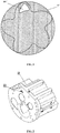
FIG. 1 is a schematic view illustrating an axial gas-supplement hole in an existing screw compressor; -
FIG. 2 is a schematic stereogram illustrating a gas-supplement hole in a screw compressor according to an embodiment of the present disclosure; -
FIG. 3 is a schematic front view illustrating a gas-supplement hole in a screw compressor according to an embodiment of the present disclosure. -
FIG. 4 is a schematic view illustrating an arrangement of gas-supplement holes in a screw compressor according to an embodiment of the present disclosure. - 10'. body; 201'. axial gas-supplement hole; 10. body; 201. gas-supplement hole; 31. first group; 40. male screw.
- The embodiments of the present disclosure are described in detail below, and the examples of the embodiments are illustrated in the accompanying drawings. The same or similar reference signs mean the same or similar elements, or elements having the same or similar functions. The embodiments described below with reference to the accompanying drawings are illustrative and used to interpret the disclosure, but not intended to limit the present disclosure.
- The present disclosure provides a screw compressor. In an embodiment, as shown in
FIG. 2 andFIG. 3 , the screw compressor includes abody 10. Thebody 10 includes a housing, in which a compression chamber is provided, and a gas-supplement channel is provided in thebody 10. The gas-supplement channel has a plurality of gas-supplement holes 201 communicating with the compression chamber. - For example, the gas-
supplement hole 201 is an axial gas-supplement hole, that is, the gas-supplement hole 201 is parallel with the axis of thebody 10, which is beneficial for processing. In addition, the gas-supplement hole 201 may be arranged to be inclined relative to the axis of thebody 10. - In the present embodiment, the number of the gas-
supplement holes 201 of the gas-supplement channel for communicating with the compression chamber is multiple, so that in the case that the space available in thebody 10 for disposing the gas-supplement holes 201 is limited, the hole diameter of each of the gas-supplement holes 201 is smaller. - The principle and working process of the screw compressor provided by the present disclosure will be described in detail below with reference to the accompanying drawings.
- Taking a screw compressor being a twin-screw compressor as an example, specifically, the screw compressor further includes a couple of parallel and mutual engaged male and female screws, and a driving mechanism. The driving mechanism is connected to the male screw and configured to drive the male screw to rotate, thereby driving the female screw engaged with the male screw to rotate. One end of the
body 10 is provided with a gas intake, and the other end of thebody 10 is provided with an exhaust port. The gas intake and the exhaust port are respectively located at two sides of the female and male screws. - When the screw compressor is working, driven by the driving mechanism, the male screw and the female screw rotate in opposite directions with each other. When the compression chamber between the female and male screws is communicated with the gas intake, the gas enters the compression chamber between the female and male screws through the gas intake; and after being compressed, the gas is discharged from the exhaust port when the compression chamber is communicated with the exhaust port.
- In the above process, when the compression chamber is communicated with the gas-
supplement hole 201, the gas is supplemented into the compression chamber through the gas-supplement channel, to improve the compression efficiency of the screw compressor. When the gas in the gas-supplement channel passes through the gas-supplement channel, the gas volume passing through the gas-supplement channel is a fixed value, therefore a total gas volume passing through the plurality of gas-supplement holes 201 is a fixed value. Since the number of the gas-supplement holes 201 is multiple, in the case that the total gas volume is constant, the hole diameter of each of the gas-supplement holes 201 is relatively smaller, and the gas flow pulsation generated by the gas passing through the gas-supplement holes 201 is smaller, thereby reducing the noise formed when the gas is supplemented into the compression chamber. - In the above, the principle and process of the present disclosure are described in detail by taking the screw compressor being a twin-screw compressor as an example. However, it should be noted that the screw compressor provided by the present disclosure may also be other possible structures, and is not limited to the above-mentioned twin-screw compressor.
- In the present embodiment, the shape of each of the gas-
supplement holes 201 can be various regular shapes such as a circle, an ellipse, a round rectangle, a polygon and so on, and can also be other irregular shapes. In practical applications, the shape of the gas-supplement hole 201 can be configured to be any shape desired or capable of achieving the corresponding purpose according to requirements. - Preferably, a radial dimension of each of the gas-
supplement holes 201 is not greater than 6 mm. When the gas-supplement hole is circular, the radial dimension is the diameter of the hole. Such setting defines the maximum dimension of the hole diameter of the gas-supplement hole 201, i.e., the hole diameter is limited within a range of not greater than 6 mm, which can better reduce the gas flow pulsation in the gas-supplement process, thereby enabling the noise to be lower. - Furthermore, the radial dimension of each of the gas-
supplement holes 201 is not less than 2 mm. When the gas-supplement hole 201 is circular, the radial dimension is the diameter of the hole. The shape of the axial gas-supplement hole 201 is configured to be circular for easy processing, thereby reducing the processing cost. As shown inFIG. 3 , each of the gas-supplement holes 201 has a diameter of 5 mm. - Preferably, referring to
FIG. 4 , amale screw 40 and a female screw are provided in thebody 10, and a plurality of gas-supplement holes 201 are arranged in a shape corresponding to the tooth root of themale screw 40. Such an arrangement can reduce the gas flow pulsation in the gas-supplement process, which helps to reduce the noise in the gas-supplement process. - In the present embodiment, as shown in
FIG. 2 , thebody 10 further includes an exhaust end bearing seat. The exhaust end bearing seat is disposed at an end of the housing, and at least a portion of the length of the gas-supplement channel can be disposed in the exhaust end bearing seat of thebody 10. The body structure shown inFIGS. 2 and3 is the exhaust end bearing seat. - In an embodiment, a first part of the length section of the gas-supplement channel is disposed in the exhaust end bearing seat; a second part of the length section of the gas-supplement channel is disposed in the housing, and the gas-
supplement holes 201 are disposed in the exhaust end bearing seat. The gas supplemented into the compressor first enters into the second part of the length section the gas-supplement channel, which is located in the housing, then enters the first part of the length section of the gas-supplement channel, which is located in the exhaust end bearing seat, and then enters the compression chamber of the body through the gas-supplement hole 201. - In the screw compressor provided by the present embodiment, the number of the gas-
supplement holes 201 in the gas-supplement channel for communicating with the compression chamber is multiple, so that in the case that the space available in thebody 10 for disposing the gas-supplement holes 201 is limited, each of the gas-supplement holes 201 has a smaller hole diameter. In the gas-supplement process, compared with the gas-supplement hole with a larger hole diameter in the prior art, the screw compressor provided by the present disclosure has a larger number of gas-supplement holes 201 with smaller hole diameter, which is more beneficial for reducing the gas flow pulsation, and helps to reduce the noise in the gas-supplement process. - As shown in
FIG. 4 , at least two gas-supplement holes 201 are arranged to form afirst group 31, and at least three gas-supplement holes 201 are arranged in thefirst group 31. Centers of all gas-supplement holes 201 in thefirst group 31 form an arc. The arc and themale screw 40 are concentric. An arc at the position indicated by 31 inFIG. 4 , is the arc formed by the centers of a plurality of gas-supplement holes 201 in thefirst group 31. - The contour B of the gas-supplement channel is determined by the position of the
male screw 40 and the exhaust channel of the screw compressor, and a distance from the center of the gas-supplement hole 201 in the outer layer to the contour B of the gas-supplement channel is a fixed value. Under the premise that the exhaust channel of the screw compressor and themale screw 40 are fixed, the shape of the contour B is also fixed, that is, the shape of the contour B is also the cross-sectional shape of the original gas-supplement channel. The present disclosure also provides an air conditioning apparatus including, in this embodiment, the screw compressor in the above-described embodiments of the present disclosure.
Claims (11)
- A screw compressor, characterized by comprising:a body (10), comprising a housing, in which a compression chamber is provided, anda gas-supplement channel, disposed in the body (10), the gas-supplement channel having at least two gas-supplement holes (201) communicated with the compression chamber.
- The screw compressor according to claim 1, characterized in that the gas-supplement holes (201) are disposed along an axial direction of the body (10).
- The screw compressor according to claim 1, characterized in that a shape of cross section of each gas-supplement hole (201) is any one of a circle, an ellipse, a round rectangle and a polygon.
- The screw compressor according to claim 1, characterized in that a radial dimension of each of the gas-supplement holes (201) is not greater than 6 mm, or the radial dimension of each of the gas-supplement holes (201) is not less than 2 mm.
- The screw compressor according to claim 4, characterized in that a shape of cross section of each gas-supplement hole (201) is a circle, and each of the gas-supplement holes (201) has a diameter of 5 mm.
- The screw compressor according to claim 1, characterized by further comprising a male screw (40) and a female screw disposed in the compression chamber; wherein at least a portion of the gas-supplement holes (201) are arranged in a shape corresponding to a partial outer contour of the male screw (40).
- The screw compressor according to claim 6, characterized in that at least three gas-supplement holes (201) are arranged to form a first group (31); and centers of the gas-supplement holes (201) in the first group (31) are arranged to form an arc which is concentric with the male screw (40).
- The screw compressor according to claim 6, characterized in that a contour of the gas-supplement channel is determined by a position of the male screw and an exhaust channel of the screw compressor; and a distance from a center of each gas-supplement hole (201) disposed in an outer layer to a contour of the gas-supplement channel is a fixed value.
- The screw compressor according to claim 1, characterized in that the body (10) further comprises:
an exhaust end bearing seat, provided at an end of the housing; wherein at least a first part of a length section of the gas-supplement channel is disposed in the exhaust end bearing seat, and the gas-supplement holes (201) are provided in the exhaust end bearing seat. - An air conditioning apparatus comprising the screw compressor of claim 1.
- A refrigeration apparatus comprising the screw compressor of claim 1.
Applications Claiming Priority (2)
| Application Number | Priority Date | Filing Date | Title |
|---|---|---|---|
| CN201710283983.8A CN106979160A (en) | 2017-04-26 | 2017-04-26 | Screw compressor, air conditioner and refrigerating device |
| PCT/CN2017/119427 WO2018196427A1 (en) | 2017-04-26 | 2017-12-28 | Screw compressor, air conditioning device and refrigerating device |
Publications (3)
| Publication Number | Publication Date |
|---|---|
| EP3617516A4 EP3617516A4 (en) | 2020-03-04 |
| EP3617516A1 true EP3617516A1 (en) | 2020-03-04 |
| EP3617516B1 EP3617516B1 (en) | 2021-10-06 |
Family
ID=59341594
Family Applications (1)
| Application Number | Title | Priority Date | Filing Date |
|---|---|---|---|
| EP17907068.5A Active EP3617516B1 (en) | 2017-04-26 | 2017-12-28 | Screw compressor, air conditioning device and refrigerating device |
Country Status (5)
| Country | Link |
|---|---|
| US (1) | US20200049148A1 (en) |
| EP (1) | EP3617516B1 (en) |
| CN (1) | CN106979160A (en) |
| PH (1) | PH12019502419B1 (en) |
| WO (1) | WO2018196427A1 (en) |
Families Citing this family (2)
| Publication number | Priority date | Publication date | Assignee | Title |
|---|---|---|---|---|
| CN106979160A (en) * | 2017-04-26 | 2017-07-25 | 珠海格力电器股份有限公司 | Screw compressor, air conditioner and refrigerating device |
| CN111536043B (en) * | 2020-05-06 | 2025-10-17 | 珠海凌达压缩机有限公司 | Air supplementing and enthalpy increasing structure and compressor with same |
Family Cites Families (19)
| Publication number | Priority date | Publication date | Assignee | Title |
|---|---|---|---|---|
| JPS6285190A (en) * | 1985-10-09 | 1987-04-18 | Kobe Steel Ltd | Screw type vacuum pump |
| CN1007076B (en) * | 1987-02-27 | 1990-03-07 | 武汉冷冻机厂 | An exhaust end seat of an oil-injected screw refrigeration compressor |
| NL8900694A (en) * | 1989-03-21 | 1990-10-16 | Grass Air Holding Bv | SCREW COMPRESSOR AND METHOD FOR ITS OPERATION. |
| JPH06280598A (en) * | 1993-03-24 | 1994-10-04 | Honda Motor Co Ltd | Measuring device for supercharging pressure |
| CN1240944C (en) * | 2002-04-09 | 2006-02-08 | 赵之海 | Vortex compressor with gas compensation function |
| JP4140488B2 (en) * | 2003-09-09 | 2008-08-27 | ダイキン工業株式会社 | Screw compressor and refrigeration equipment |
| US20070092393A1 (en) * | 2005-10-26 | 2007-04-26 | General Electric Company | Gas release port for oil-free screw compressor |
| JP4183021B1 (en) * | 2007-06-11 | 2008-11-19 | ダイキン工業株式会社 | Compressor and refrigeration equipment |
| US8056543B2 (en) * | 2009-04-24 | 2011-11-15 | GM Global Technology Operations LLC | Tuning device with combined backflow function |
| CN201836053U (en) * | 2010-04-26 | 2011-05-18 | 上海维尔泰克螺杆机械有限公司 | Screw rod compressor |
| CN202851353U (en) * | 2012-09-06 | 2013-04-03 | 安徽东升机电有限责任公司 | Heat pump type compressor of electric automobile air conditioner |
| WO2016186692A1 (en) * | 2015-05-19 | 2016-11-24 | Eaton Corporation | Supercharger mesh assembly |
| JP2018517086A (en) * | 2015-06-11 | 2018-06-28 | イートン コーポレーションEaton Corporation | Bearing plate noise damper |
| CN205013302U (en) * | 2015-08-31 | 2016-02-03 | 珠海格力电器股份有限公司 | Air supplement structure and screw compressor |
| CN204962009U (en) * | 2015-09-01 | 2016-01-13 | 奇瑞汽车股份有限公司 | Novel vehicle air conditioner rectifying valve |
| CN105736377A (en) * | 2016-04-11 | 2016-07-06 | 珠海格力节能环保制冷技术研究中心有限公司 | Compressor structure |
| CN205858689U (en) * | 2016-06-24 | 2017-01-04 | 珠海格力电器股份有限公司 | Exhaust bearing seat and screw compressor |
| CN106979160A (en) * | 2017-04-26 | 2017-07-25 | 珠海格力电器股份有限公司 | Screw compressor, air conditioner and refrigerating device |
| CN206889265U (en) * | 2017-04-26 | 2018-01-16 | 珠海格力电器股份有限公司 | Screw compressor, air conditioner and refrigerating device |
-
2017
- 2017-04-26 CN CN201710283983.8A patent/CN106979160A/en active Pending
- 2017-12-28 WO PCT/CN2017/119427 patent/WO2018196427A1/en not_active Ceased
- 2017-12-28 US US16/608,763 patent/US20200049148A1/en not_active Abandoned
- 2017-12-28 EP EP17907068.5A patent/EP3617516B1/en active Active
- 2017-12-28 PH PH1/2019/502419A patent/PH12019502419B1/en unknown
Also Published As
| Publication number | Publication date |
|---|---|
| PH12019502419A1 (en) | 2020-07-06 |
| WO2018196427A1 (en) | 2018-11-01 |
| CN106979160A (en) | 2017-07-25 |
| EP3617516B1 (en) | 2021-10-06 |
| PH12019502419B1 (en) | 2023-08-04 |
| EP3617516A4 (en) | 2020-03-04 |
| US20200049148A1 (en) | 2020-02-13 |
Similar Documents
| Publication | Publication Date | Title |
|---|---|---|
| US20170089330A1 (en) | Air compressor core | |
| WO2019024562A1 (en) | Compressor and refrigeration apparatus having same | |
| US20200049148A1 (en) | Screw Compressor, Air Conditioning Apparatus and Refrigeration Apparatus | |
| EP2565456B1 (en) | Screw compressor | |
| US12152589B2 (en) | Compressor and air conditioning system | |
| EP4421322A1 (en) | Screw compressor and refrigeration system having the same | |
| CN104912808A (en) | Compressing mechanism and low-back-pressure rotation type compressor with same | |
| CN103423909B (en) | Spiral compression-expansiorefrigerator refrigerator | |
| CN106762642A (en) | Rotary compressor | |
| CN217558545U (en) | Screw vortex two-stage compressor with adjustable interstage displacement and pressure | |
| CN116464642A (en) | Oil return throttling device and scroll compressor | |
| CN204371688U (en) | Rotary compressor | |
| CN208138142U (en) | Compressor and air conditioning unit | |
| US11408287B2 (en) | Compressor pump body, compressor, and air conditioner with a vane enlargement portion | |
| CN205117663U (en) | Multistage exhaust compression cylinder base | |
| US20240393022A1 (en) | Ejector and refrigeration system having the same | |
| CN117432629B (en) | Cylinder and roller compressor | |
| CN204371673U (en) | Scroll compressor | |
| CN207195179U (en) | Scroll compressor having a plurality of scroll members | |
| CN205638947U (en) | Refrigeration equipment, compressor and compressor cylinder body cooling structure | |
| CN206221253U (en) | Rotary compressor | |
| CN224260479U (en) | A compressor and heating and ventilation equipment | |
| CN204783690U (en) | Compressing mechanism and have its low back pressure rotary compressor | |
| CN222025925U (en) | Pump body structure of compressor and compressor | |
| CN103573654B (en) | A kind of Multi-stage ram compressor and apply its electromotor |
Legal Events
| Date | Code | Title | Description |
|---|---|---|---|
| STAA | Information on the status of an ep patent application or granted ep patent |
Free format text: STATUS: THE INTERNATIONAL PUBLICATION HAS BEEN MADE |
|
| PUAI | Public reference made under article 153(3) epc to a published international application that has entered the european phase |
Free format text: ORIGINAL CODE: 0009012 |
|
| STAA | Information on the status of an ep patent application or granted ep patent |
Free format text: STATUS: REQUEST FOR EXAMINATION WAS MADE |
|
| 17P | Request for examination filed |
Effective date: 20191030 |
|
| A4 | Supplementary search report drawn up and despatched |
Effective date: 20191210 |
|
| AK | Designated contracting states |
Kind code of ref document: A1 Designated state(s): AL AT BE BG CH CY CZ DE DK EE ES FI FR GB GR HR HU IE IS IT LI LT LU LV MC MK MT NL NO PL PT RO RS SE SI SK SM TR |
|
| AX | Request for extension of the european patent |
Extension state: BA ME |
|
| DAV | Request for validation of the european patent (deleted) | ||
| DAX | Request for extension of the european patent (deleted) | ||
| STAA | Information on the status of an ep patent application or granted ep patent |
Free format text: STATUS: EXAMINATION IS IN PROGRESS |
|
| 17Q | First examination report despatched |
Effective date: 20201110 |
|
| GRAP | Despatch of communication of intention to grant a patent |
Free format text: ORIGINAL CODE: EPIDOSNIGR1 |
|
| STAA | Information on the status of an ep patent application or granted ep patent |
Free format text: STATUS: GRANT OF PATENT IS INTENDED |
|
| INTG | Intention to grant announced |
Effective date: 20210517 |
|
| GRAS | Grant fee paid |
Free format text: ORIGINAL CODE: EPIDOSNIGR3 |
|
| GRAA | (expected) grant |
Free format text: ORIGINAL CODE: 0009210 |
|
| STAA | Information on the status of an ep patent application or granted ep patent |
Free format text: STATUS: THE PATENT HAS BEEN GRANTED |
|
| AK | Designated contracting states |
Kind code of ref document: B1 Designated state(s): AL AT BE BG CH CY CZ DE DK EE ES FI FR GB GR HR HU IE IS IT LI LT LU LV MC MK MT NL NO PL PT RO RS SE SI SK SM TR |
|
| REG | Reference to a national code |
Ref country code: GB Ref legal event code: FG4D |
|
| REG | Reference to a national code |
Ref country code: CH Ref legal event code: EP Ref country code: AT Ref legal event code: REF Ref document number: 1436468 Country of ref document: AT Kind code of ref document: T Effective date: 20211015 |
|
| REG | Reference to a national code |
Ref country code: IE Ref legal event code: FG4D |
|
| REG | Reference to a national code |
Ref country code: DE Ref legal event code: R096 Ref document number: 602017047378 Country of ref document: DE |
|
| REG | Reference to a national code |
Ref country code: LT Ref legal event code: MG9D |
|
| REG | Reference to a national code |
Ref country code: NL Ref legal event code: MP Effective date: 20211006 |
|
| REG | Reference to a national code |
Ref country code: AT Ref legal event code: MK05 Ref document number: 1436468 Country of ref document: AT Kind code of ref document: T Effective date: 20211006 |
|
| PG25 | Lapsed in a contracting state [announced via postgrant information from national office to epo] |
Ref country code: RS Free format text: LAPSE BECAUSE OF FAILURE TO SUBMIT A TRANSLATION OF THE DESCRIPTION OR TO PAY THE FEE WITHIN THE PRESCRIBED TIME-LIMIT Effective date: 20211006 Ref country code: LT Free format text: LAPSE BECAUSE OF FAILURE TO SUBMIT A TRANSLATION OF THE DESCRIPTION OR TO PAY THE FEE WITHIN THE PRESCRIBED TIME-LIMIT Effective date: 20211006 Ref country code: FI Free format text: LAPSE BECAUSE OF FAILURE TO SUBMIT A TRANSLATION OF THE DESCRIPTION OR TO PAY THE FEE WITHIN THE PRESCRIBED TIME-LIMIT Effective date: 20211006 Ref country code: BG Free format text: LAPSE BECAUSE OF FAILURE TO SUBMIT A TRANSLATION OF THE DESCRIPTION OR TO PAY THE FEE WITHIN THE PRESCRIBED TIME-LIMIT Effective date: 20220106 Ref country code: AT Free format text: LAPSE BECAUSE OF FAILURE TO SUBMIT A TRANSLATION OF THE DESCRIPTION OR TO PAY THE FEE WITHIN THE PRESCRIBED TIME-LIMIT Effective date: 20211006 |
|
| PG25 | Lapsed in a contracting state [announced via postgrant information from national office to epo] |
Ref country code: IS Free format text: LAPSE BECAUSE OF FAILURE TO SUBMIT A TRANSLATION OF THE DESCRIPTION OR TO PAY THE FEE WITHIN THE PRESCRIBED TIME-LIMIT Effective date: 20220206 Ref country code: SE Free format text: LAPSE BECAUSE OF FAILURE TO SUBMIT A TRANSLATION OF THE DESCRIPTION OR TO PAY THE FEE WITHIN THE PRESCRIBED TIME-LIMIT Effective date: 20211006 Ref country code: PT Free format text: LAPSE BECAUSE OF FAILURE TO SUBMIT A TRANSLATION OF THE DESCRIPTION OR TO PAY THE FEE WITHIN THE PRESCRIBED TIME-LIMIT Effective date: 20220207 Ref country code: PL Free format text: LAPSE BECAUSE OF FAILURE TO SUBMIT A TRANSLATION OF THE DESCRIPTION OR TO PAY THE FEE WITHIN THE PRESCRIBED TIME-LIMIT Effective date: 20211006 Ref country code: NO Free format text: LAPSE BECAUSE OF FAILURE TO SUBMIT A TRANSLATION OF THE DESCRIPTION OR TO PAY THE FEE WITHIN THE PRESCRIBED TIME-LIMIT Effective date: 20220106 Ref country code: NL Free format text: LAPSE BECAUSE OF FAILURE TO SUBMIT A TRANSLATION OF THE DESCRIPTION OR TO PAY THE FEE WITHIN THE PRESCRIBED TIME-LIMIT Effective date: 20211006 Ref country code: LV Free format text: LAPSE BECAUSE OF FAILURE TO SUBMIT A TRANSLATION OF THE DESCRIPTION OR TO PAY THE FEE WITHIN THE PRESCRIBED TIME-LIMIT Effective date: 20211006 Ref country code: HR Free format text: LAPSE BECAUSE OF FAILURE TO SUBMIT A TRANSLATION OF THE DESCRIPTION OR TO PAY THE FEE WITHIN THE PRESCRIBED TIME-LIMIT Effective date: 20211006 Ref country code: GR Free format text: LAPSE BECAUSE OF FAILURE TO SUBMIT A TRANSLATION OF THE DESCRIPTION OR TO PAY THE FEE WITHIN THE PRESCRIBED TIME-LIMIT Effective date: 20220107 Ref country code: ES Free format text: LAPSE BECAUSE OF FAILURE TO SUBMIT A TRANSLATION OF THE DESCRIPTION OR TO PAY THE FEE WITHIN THE PRESCRIBED TIME-LIMIT Effective date: 20211006 |
|
| REG | Reference to a national code |
Ref country code: DE Ref legal event code: R097 Ref document number: 602017047378 Country of ref document: DE |
|
| PG25 | Lapsed in a contracting state [announced via postgrant information from national office to epo] |
Ref country code: SM Free format text: LAPSE BECAUSE OF FAILURE TO SUBMIT A TRANSLATION OF THE DESCRIPTION OR TO PAY THE FEE WITHIN THE PRESCRIBED TIME-LIMIT Effective date: 20211006 Ref country code: SK Free format text: LAPSE BECAUSE OF FAILURE TO SUBMIT A TRANSLATION OF THE DESCRIPTION OR TO PAY THE FEE WITHIN THE PRESCRIBED TIME-LIMIT Effective date: 20211006 Ref country code: RO Free format text: LAPSE BECAUSE OF FAILURE TO SUBMIT A TRANSLATION OF THE DESCRIPTION OR TO PAY THE FEE WITHIN THE PRESCRIBED TIME-LIMIT Effective date: 20211006 Ref country code: MC Free format text: LAPSE BECAUSE OF FAILURE TO SUBMIT A TRANSLATION OF THE DESCRIPTION OR TO PAY THE FEE WITHIN THE PRESCRIBED TIME-LIMIT Effective date: 20211006 Ref country code: EE Free format text: LAPSE BECAUSE OF FAILURE TO SUBMIT A TRANSLATION OF THE DESCRIPTION OR TO PAY THE FEE WITHIN THE PRESCRIBED TIME-LIMIT Effective date: 20211006 Ref country code: DK Free format text: LAPSE BECAUSE OF FAILURE TO SUBMIT A TRANSLATION OF THE DESCRIPTION OR TO PAY THE FEE WITHIN THE PRESCRIBED TIME-LIMIT Effective date: 20211006 Ref country code: CZ Free format text: LAPSE BECAUSE OF FAILURE TO SUBMIT A TRANSLATION OF THE DESCRIPTION OR TO PAY THE FEE WITHIN THE PRESCRIBED TIME-LIMIT Effective date: 20211006 |
|
| REG | Reference to a national code |
Ref country code: CH Ref legal event code: PL |
|
| PLBE | No opposition filed within time limit |
Free format text: ORIGINAL CODE: 0009261 |
|
| STAA | Information on the status of an ep patent application or granted ep patent |
Free format text: STATUS: NO OPPOSITION FILED WITHIN TIME LIMIT |
|
| 26N | No opposition filed |
Effective date: 20220707 |
|
| REG | Reference to a national code |
Ref country code: BE Ref legal event code: MM Effective date: 20211231 |
|
| PG25 | Lapsed in a contracting state [announced via postgrant information from national office to epo] |
Ref country code: LU Free format text: LAPSE BECAUSE OF NON-PAYMENT OF DUE FEES Effective date: 20211228 Ref country code: IE Free format text: LAPSE BECAUSE OF NON-PAYMENT OF DUE FEES Effective date: 20211228 Ref country code: AL Free format text: LAPSE BECAUSE OF FAILURE TO SUBMIT A TRANSLATION OF THE DESCRIPTION OR TO PAY THE FEE WITHIN THE PRESCRIBED TIME-LIMIT Effective date: 20211006 |
|
| PG25 | Lapsed in a contracting state [announced via postgrant information from national office to epo] |
Ref country code: SI Free format text: LAPSE BECAUSE OF FAILURE TO SUBMIT A TRANSLATION OF THE DESCRIPTION OR TO PAY THE FEE WITHIN THE PRESCRIBED TIME-LIMIT Effective date: 20211006 Ref country code: BE Free format text: LAPSE BECAUSE OF NON-PAYMENT OF DUE FEES Effective date: 20211231 |
|
| PG25 | Lapsed in a contracting state [announced via postgrant information from national office to epo] |
Ref country code: LI Free format text: LAPSE BECAUSE OF NON-PAYMENT OF DUE FEES Effective date: 20211231 Ref country code: CH Free format text: LAPSE BECAUSE OF NON-PAYMENT OF DUE FEES Effective date: 20211231 |
|
| PG25 | Lapsed in a contracting state [announced via postgrant information from national office to epo] |
Ref country code: IT Free format text: LAPSE BECAUSE OF FAILURE TO SUBMIT A TRANSLATION OF THE DESCRIPTION OR TO PAY THE FEE WITHIN THE PRESCRIBED TIME-LIMIT Effective date: 20211006 |
|
| PG25 | Lapsed in a contracting state [announced via postgrant information from national office to epo] |
Ref country code: CY Free format text: LAPSE BECAUSE OF FAILURE TO SUBMIT A TRANSLATION OF THE DESCRIPTION OR TO PAY THE FEE WITHIN THE PRESCRIBED TIME-LIMIT Effective date: 20211006 |
|
| P01 | Opt-out of the competence of the unified patent court (upc) registered |
Effective date: 20230530 |
|
| PG25 | Lapsed in a contracting state [announced via postgrant information from national office to epo] |
Ref country code: HU Free format text: LAPSE BECAUSE OF FAILURE TO SUBMIT A TRANSLATION OF THE DESCRIPTION OR TO PAY THE FEE WITHIN THE PRESCRIBED TIME-LIMIT; INVALID AB INITIO Effective date: 20171228 |
|
| PG25 | Lapsed in a contracting state [announced via postgrant information from national office to epo] |
Ref country code: MK Free format text: LAPSE BECAUSE OF FAILURE TO SUBMIT A TRANSLATION OF THE DESCRIPTION OR TO PAY THE FEE WITHIN THE PRESCRIBED TIME-LIMIT Effective date: 20211006 |
|
| PG25 | Lapsed in a contracting state [announced via postgrant information from national office to epo] |
Ref country code: TR Free format text: LAPSE BECAUSE OF FAILURE TO SUBMIT A TRANSLATION OF THE DESCRIPTION OR TO PAY THE FEE WITHIN THE PRESCRIBED TIME-LIMIT Effective date: 20211006 |
|
| PG25 | Lapsed in a contracting state [announced via postgrant information from national office to epo] |
Ref country code: MT Free format text: LAPSE BECAUSE OF FAILURE TO SUBMIT A TRANSLATION OF THE DESCRIPTION OR TO PAY THE FEE WITHIN THE PRESCRIBED TIME-LIMIT Effective date: 20211006 |
|
| PGFP | Annual fee paid to national office [announced via postgrant information from national office to epo] |
Ref country code: GB Payment date: 20251111 Year of fee payment: 9 |
|
| PGFP | Annual fee paid to national office [announced via postgrant information from national office to epo] |
Ref country code: FR Payment date: 20251110 Year of fee payment: 9 |
|
| PGFP | Annual fee paid to national office [announced via postgrant information from national office to epo] |
Ref country code: DE Payment date: 20251222 Year of fee payment: 9 |