EP3617479B1 - Getriebefan mit reduzierter öltankgrösse - Google Patents
Getriebefan mit reduzierter öltankgrösse Download PDFInfo
- Publication number
- EP3617479B1 EP3617479B1 EP19204709.0A EP19204709A EP3617479B1 EP 3617479 B1 EP3617479 B1 EP 3617479B1 EP 19204709 A EP19204709 A EP 19204709A EP 3617479 B1 EP3617479 B1 EP 3617479B1
- Authority
- EP
- European Patent Office
- Prior art keywords
- equal
- oil
- gear reduction
- engine
- fan
- Prior art date
- Legal status (The legal status is an assumption and is not a legal conclusion. Google has not performed a legal analysis and makes no representation as to the accuracy of the status listed.)
- Active
Links
- 230000009467 reduction Effects 0.000 claims description 24
- 238000000034 method Methods 0.000 claims description 7
- 238000005461 lubrication Methods 0.000 claims description 2
- 239000000446 fuel Substances 0.000 description 6
- 239000000314 lubricant Substances 0.000 description 3
- 238000002485 combustion reaction Methods 0.000 description 2
- 230000003068 static effect Effects 0.000 description 2
- 230000008859 change Effects 0.000 description 1
- 238000004891 communication Methods 0.000 description 1
- 230000006835 compression Effects 0.000 description 1
- 238000007906 compression Methods 0.000 description 1
- 230000007246 mechanism Effects 0.000 description 1
- 238000012986 modification Methods 0.000 description 1
- 230000004048 modification Effects 0.000 description 1
- 230000004044 response Effects 0.000 description 1
Images
Classifications
-
- F—MECHANICAL ENGINEERING; LIGHTING; HEATING; WEAPONS; BLASTING
- F02—COMBUSTION ENGINES; HOT-GAS OR COMBUSTION-PRODUCT ENGINE PLANTS
- F02C—GAS-TURBINE PLANTS; AIR INTAKES FOR JET-PROPULSION PLANTS; CONTROLLING FUEL SUPPLY IN AIR-BREATHING JET-PROPULSION PLANTS
- F02C7/00—Features, components parts, details or accessories, not provided for in, or of interest apart form groups F02C1/00 - F02C6/00; Air intakes for jet-propulsion plants
- F02C7/36—Power transmission arrangements between the different shafts of the gas turbine plant, or between the gas-turbine plant and the power user
-
- F—MECHANICAL ENGINEERING; LIGHTING; HEATING; WEAPONS; BLASTING
- F01—MACHINES OR ENGINES IN GENERAL; ENGINE PLANTS IN GENERAL; STEAM ENGINES
- F01D—NON-POSITIVE DISPLACEMENT MACHINES OR ENGINES, e.g. STEAM TURBINES
- F01D25/00—Component parts, details, or accessories, not provided for in, or of interest apart from, other groups
- F01D25/18—Lubricating arrangements
- F01D25/20—Lubricating arrangements using lubrication pumps
-
- F—MECHANICAL ENGINEERING; LIGHTING; HEATING; WEAPONS; BLASTING
- F02—COMBUSTION ENGINES; HOT-GAS OR COMBUSTION-PRODUCT ENGINE PLANTS
- F02C—GAS-TURBINE PLANTS; AIR INTAKES FOR JET-PROPULSION PLANTS; CONTROLLING FUEL SUPPLY IN AIR-BREATHING JET-PROPULSION PLANTS
- F02C7/00—Features, components parts, details or accessories, not provided for in, or of interest apart form groups F02C1/00 - F02C6/00; Air intakes for jet-propulsion plants
- F02C7/06—Arrangements of bearings; Lubricating
-
- F—MECHANICAL ENGINEERING; LIGHTING; HEATING; WEAPONS; BLASTING
- F02—COMBUSTION ENGINES; HOT-GAS OR COMBUSTION-PRODUCT ENGINE PLANTS
- F02K—JET-PROPULSION PLANTS
- F02K3/00—Plants including a gas turbine driving a compressor or a ducted fan
- F02K3/02—Plants including a gas turbine driving a compressor or a ducted fan in which part of the working fluid by-passes the turbine and combustion chamber
- F02K3/04—Plants including a gas turbine driving a compressor or a ducted fan in which part of the working fluid by-passes the turbine and combustion chamber the plant including ducted fans, i.e. fans with high volume, low pressure outputs, for augmenting the jet thrust, e.g. of double-flow type
- F02K3/06—Plants including a gas turbine driving a compressor or a ducted fan in which part of the working fluid by-passes the turbine and combustion chamber the plant including ducted fans, i.e. fans with high volume, low pressure outputs, for augmenting the jet thrust, e.g. of double-flow type with front fan
-
- F—MECHANICAL ENGINEERING; LIGHTING; HEATING; WEAPONS; BLASTING
- F16—ENGINEERING ELEMENTS AND UNITS; GENERAL MEASURES FOR PRODUCING AND MAINTAINING EFFECTIVE FUNCTIONING OF MACHINES OR INSTALLATIONS; THERMAL INSULATION IN GENERAL
- F16H—GEARING
- F16H57/00—General details of gearing
- F16H57/04—Features relating to lubrication or cooling or heating
- F16H57/042—Guidance of lubricant
- F16H57/0427—Guidance of lubricant on rotary parts, e.g. using baffles for collecting lubricant by centrifugal force
-
- F—MECHANICAL ENGINEERING; LIGHTING; HEATING; WEAPONS; BLASTING
- F16—ENGINEERING ELEMENTS AND UNITS; GENERAL MEASURES FOR PRODUCING AND MAINTAINING EFFECTIVE FUNCTIONING OF MACHINES OR INSTALLATIONS; THERMAL INSULATION IN GENERAL
- F16H—GEARING
- F16H57/00—General details of gearing
- F16H57/04—Features relating to lubrication or cooling or heating
- F16H57/0467—Elements of gearings to be lubricated, cooled or heated
- F16H57/0479—Gears or bearings on planet carriers
-
- F—MECHANICAL ENGINEERING; LIGHTING; HEATING; WEAPONS; BLASTING
- F16—ENGINEERING ELEMENTS AND UNITS; GENERAL MEASURES FOR PRODUCING AND MAINTAINING EFFECTIVE FUNCTIONING OF MACHINES OR INSTALLATIONS; THERMAL INSULATION IN GENERAL
- F16H—GEARING
- F16H57/00—General details of gearing
- F16H57/04—Features relating to lubrication or cooling or heating
- F16H57/048—Type of gearings to be lubricated, cooled or heated
- F16H57/0482—Gearings with gears having orbital motion
- F16H57/0486—Gearings with gears having orbital motion with fixed gear ratio
-
- F—MECHANICAL ENGINEERING; LIGHTING; HEATING; WEAPONS; BLASTING
- F05—INDEXING SCHEMES RELATING TO ENGINES OR PUMPS IN VARIOUS SUBCLASSES OF CLASSES F01-F04
- F05D—INDEXING SCHEME FOR ASPECTS RELATING TO NON-POSITIVE-DISPLACEMENT MACHINES OR ENGINES, GAS-TURBINES OR JET-PROPULSION PLANTS
- F05D2220/00—Application
- F05D2220/30—Application in turbines
- F05D2220/32—Application in turbines in gas turbines
- F05D2220/323—Application in turbines in gas turbines for aircraft propulsion, e.g. jet engines
-
- F—MECHANICAL ENGINEERING; LIGHTING; HEATING; WEAPONS; BLASTING
- F05—INDEXING SCHEMES RELATING TO ENGINES OR PUMPS IN VARIOUS SUBCLASSES OF CLASSES F01-F04
- F05D—INDEXING SCHEME FOR ASPECTS RELATING TO NON-POSITIVE-DISPLACEMENT MACHINES OR ENGINES, GAS-TURBINES OR JET-PROPULSION PLANTS
- F05D2260/00—Function
- F05D2260/40—Transmission of power
- F05D2260/403—Transmission of power through the shape of the drive components
- F05D2260/4031—Transmission of power through the shape of the drive components as in toothed gearing
- F05D2260/40311—Transmission of power through the shape of the drive components as in toothed gearing of the epicyclical, planetary or differential type
-
- F—MECHANICAL ENGINEERING; LIGHTING; HEATING; WEAPONS; BLASTING
- F05—INDEXING SCHEMES RELATING TO ENGINES OR PUMPS IN VARIOUS SUBCLASSES OF CLASSES F01-F04
- F05D—INDEXING SCHEME FOR ASPECTS RELATING TO NON-POSITIVE-DISPLACEMENT MACHINES OR ENGINES, GAS-TURBINES OR JET-PROPULSION PLANTS
- F05D2260/00—Function
- F05D2260/60—Fluid transfer
- F05D2260/608—Aeration, ventilation, dehumidification or moisture removal of closed spaces
-
- F—MECHANICAL ENGINEERING; LIGHTING; HEATING; WEAPONS; BLASTING
- F05—INDEXING SCHEMES RELATING TO ENGINES OR PUMPS IN VARIOUS SUBCLASSES OF CLASSES F01-F04
- F05D—INDEXING SCHEME FOR ASPECTS RELATING TO NON-POSITIVE-DISPLACEMENT MACHINES OR ENGINES, GAS-TURBINES OR JET-PROPULSION PLANTS
- F05D2260/00—Function
- F05D2260/98—Lubrication
-
- F—MECHANICAL ENGINEERING; LIGHTING; HEATING; WEAPONS; BLASTING
- F16—ENGINEERING ELEMENTS AND UNITS; GENERAL MEASURES FOR PRODUCING AND MAINTAINING EFFECTIVE FUNCTIONING OF MACHINES OR INSTALLATIONS; THERMAL INSULATION IN GENERAL
- F16H—GEARING
- F16H57/00—General details of gearing
- F16H57/04—Features relating to lubrication or cooling or heating
-
- F—MECHANICAL ENGINEERING; LIGHTING; HEATING; WEAPONS; BLASTING
- F16—ENGINEERING ELEMENTS AND UNITS; GENERAL MEASURES FOR PRODUCING AND MAINTAINING EFFECTIVE FUNCTIONING OF MACHINES OR INSTALLATIONS; THERMAL INSULATION IN GENERAL
- F16H—GEARING
- F16H57/00—General details of gearing
- F16H57/08—General details of gearing of gearings with members having orbital motion
-
- Y—GENERAL TAGGING OF NEW TECHNOLOGICAL DEVELOPMENTS; GENERAL TAGGING OF CROSS-SECTIONAL TECHNOLOGIES SPANNING OVER SEVERAL SECTIONS OF THE IPC; TECHNICAL SUBJECTS COVERED BY FORMER USPC CROSS-REFERENCE ART COLLECTIONS [XRACs] AND DIGESTS
- Y02—TECHNOLOGIES OR APPLICATIONS FOR MITIGATION OR ADAPTATION AGAINST CLIMATE CHANGE
- Y02T—CLIMATE CHANGE MITIGATION TECHNOLOGIES RELATED TO TRANSPORTATION
- Y02T50/00—Aeronautics or air transport
- Y02T50/60—Efficient propulsion technologies, e.g. for aircraft
Definitions
- This application relates to a gas turbine engine having a gear reduction driving a fan wherein an oil tank is of reduced size.
- Gas turbine engines are known and, typically, include a fan delivering air into a bypass duct as propulsion air.
- the fan also delivers air into a core engine where it passes to a compressor.
- the air is compressed in the compressor and delivered downstream into a combustion section where it is mixed with fuel and ignited. Products of this combustion pass downstream over turbine rotors driving them to rotate.
- the gear reduction is a source of increased heat loss.
- a geared turbofan engine creates about twice as much heat loss as a non-geared turbofan engine.
- the weight of the engine increases due to the weight of the gear reduction.
- a method of operating a gas turbine engine is provided as set forth in claim 1.
- the dwell time is less than or equal to 3.0 seconds.
- the fan rotor delivers air into a bypass duct as propulsion air and into a core engine where it passes into a compressor section.
- a bypass ratio is defined as the ratio of air delivered into the bypass duct compared to the volume of air delivered into the core engine. The bypass ratio is greater than or equal to about 6.0.
- the bypass ratio is greater than or equal to about 10.0.
- a gear ratio of the gear reduction is greater than or equal to about 2.3:1.
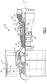
- FIG. 1 schematically illustrates a gas turbine engine 20.
- the gas turbine engine 20 is disclosed herein as a two-spool turbofan that generally incorporates a fan section 22, a compressor section 24, a combustor section 26 and a turbine section 28.
- Alternative engines might include an augmentor section (not shown) among other systems or features.
- the fan section 22 drives air along a bypass flow path B in a bypass duct defined within a nacelle 15, while the compressor section 24 drives air along a core flow path C for compression and communication into the combustor section 26 then expansion through the turbine section 28.
- the exemplary engine 20 generally includes a low speed spool 30 and a high speed spool 32 mounted for rotation about an engine central longitudinal axis A relative to an engine static structure 36 via several bearing systems 38. It should be understood that various bearing systems 38 at various locations may alternatively or additionally be provided, and the location of bearing systems 38 may be varied as appropriate to the application.
- the low speed spool 30 generally includes an inner shaft 40 that interconnects a fan 42, a first (or low) pressure compressor 44 and a first (or low) pressure turbine 46.
- the inner shaft 40 is connected to the fan 42 through a speed change mechanism, which in exemplary gas turbine engine 20 is illustrated as a geared architecture 48 to drive the fan 42 at a lower speed than the low speed spool 30.
- the high speed spool 32 includes an outer shaft 50 that interconnects a second (or high) pressure compressor 52 and a second (or high) pressure turbine 54.
- a combustor 56 is arranged in exemplary gas turbine 20 between the high pressure compressor 52 and the high pressure turbine 54.
- a mid-turbine frame 57 of the engine static structure 36 is arranged generally between the high pressure turbine 54 and the low pressure turbine 46.
- the mid-turbine frame 57 further supports bearing systems 38 in the turbine section 28.
- the inner shaft 40 and the outer shaft 50 are concentric and rotate via bearing systems 38 about the engine central longitudinal axis A which is collinear with their longitudinal axes.
- the core airflow is compressed by the low pressure compressor 44 then the high pressure compressor 52, mixed and burned with fuel in the combustor 56, then expanded over the high pressure turbine 54 and low pressure turbine 46.
- the mid-turbine frame 57 includes airfoils 59 which are in the core airflow path C.
- the turbines 46, 54 rotationally drive the respective low speed spool 30 and high speed spool 32 in response to the expansion.
- gear system 48 may be located aft of combustor section 26 or even aft of turbine section 28, and fan section 22 may be positioned forward or aft of the location of gear system 48.
- the engine 20 in one example is a high-bypass geared aircraft engine.
- the engine 20 bypass ratio is greater than or equal to about six (6), with an example embodiment being greater than about ten (10)
- the geared architecture 48 is an epicyclic gear train, such as a planetary gear system or other gear system, with a gear reduction ratio of greater than about 2.3
- the low pressure turbine 46 has a pressure ratio that is greater than about five.
- the engine 20 bypass ratio is greater than or equal to about ten (10:1)
- the fan diameter is significantly larger than that of the low pressure compressor 44
- the low pressure turbine 46 has a pressure ratio that is greater than about five 5:1.
- Low pressure turbine 46 pressure ratio is pressure measured prior to inlet of low pressure turbine 46 as related to the pressure at the outlet of the low pressure turbine 46 prior to an exhaust nozzle.
- the geared architecture 48 may be an epicycle gear train, such as a planetary gear system or other gear system, with a gear reduction ratio of greater than about 2.3:1. It should be understood, however, that the above parameters are only exemplary of one embodiment of a geared architecture engine and that the present invention is applicable to other gas turbine engines including direct drive turbofans.
- the fan section 22 of the engine 20 is designed for a particular flight condition -- typically cruise at about 0.8 Mach and about 35,000 feet (10,668 m).
- the flight condition of 0.8 Mach and 35,000 ft (10,668 m), with the engine at its best fuel consumption - also known as "bucket cruise Thrust Specific Fuel Consumption ('TSFC')" - is the industry standard parameter of lbm of fuel being burned divided by lbf of thrust the engine produces at that minimum point.
- "Low fan pressure ratio” is the pressure ratio across the fan blade alone, without a Fan Exit Guide Vane (“FEGV”) system.
- the low fan pressure ratio as disclosed herein according to one non-limiting embodiment is less than about 1.45.
- the "Low corrected fan tip speed" as disclosed herein according to one non-limiting embodiment is less than about 1150 ft / second (350.5 m/s).
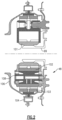
- a flexible shaft 99 which is driven by the turbine 46, drives a sun gear 101 which, in turn, engages and drives intermediate gears 102.
- the intermediate gears 102 may be planet gears of a planetary epicyclic gear system.
- the intermediate gears 102 may be star gears of a star epicyclic gear system.
- the intermediate gears 102 engage and drive a ring gear 103 to, in turn, drive an output shaft 106, which then drives the fan rotor 42.
- a planetary gear carrier (not shown) driven by planetary gears may drive the fan shaft.
- Lubricant is supplied to a journal pin 108, to the intermediate gears 102 and to other locations within the gear reduction 48.
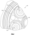
- Figure 3 shows baffles 100 which are placed circumferentially between adjacent planet gears 102.
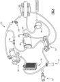
- a gutter 104 surrounds the gear reduction 48 and captures oil that has left the gear reduction. Oil from the gear reduction 48 is returned to a pump 72 (See Figure 4 ) or a tank 90 as shown schematically in Figure 4 .
- a lubricant system 70 includes the gear reduction 48 which may be structured as shown in Figures 2 and 3 . Notably, complete details of the operation of the baffle, the gutter and the other portions of the gear reduction may be as disclosed in U.S. Patent 6223616 .
- the oil may pass through an oil pressure trim orifice 82 and back to the tank 90.
- the oil may pass through a strainer 84 and then to the gear reduction 48. Oil returning from the gear reduction and, in particular, from the gutter, may pass back directly to the pump 72 or to the tank 90. This is a simplification of the overall lubricant system and, as appreciated, there may be other components.
- oil tank 90 is de-aerated by the baffles 100 and gutter system and that a dwell time in the oil tank to remove air bubbles is less than five seconds. More preferably, it may be less than or equal to about 3.0 seconds. This allows the use of oil tank 90 to be of a size roughly equivalent to the size utilized in prior non-geared gas turbine engines.
- an oil tank that holds 25 to 35 quarts (23.7 to 33.1 litres) of oil may be utilized on a geared gas turbine engine with 15,000 to 35,000 lbs (66.72 kN to 155.69 kN) in rated thrust at take-off.
- an oil tank is 35 quarts to 50 quarts (33.1 to 47.3 litres) of oil for an engine with 35,000 to 100,000 lbs (155.69 kN to 444.82 kN) in rated thrust at take-off.
Landscapes
- Engineering & Computer Science (AREA)
- General Engineering & Computer Science (AREA)
- Mechanical Engineering (AREA)
- Chemical & Material Sciences (AREA)
- Combustion & Propulsion (AREA)
- Retarders (AREA)
- General Details Of Gearings (AREA)
- Lubrication Of Internal Combustion Engines (AREA)
- Lubrication Details And Ventilation Of Internal Combustion Engines (AREA)
Claims (5)
- Verfahren zum Betreiben eines Gasturbinentriebwerks (20) mit einem Nennschub beim Start von mehr als 35.000 lbs (155,69 kN) und weniger als oder gleich 100.000 lbs (444.82 kN), wobei das Verfahren Folgendes umfasst:Antreiben einer Untersetzung (48) unter Verwendung einer Fan-Antriebsturbine (46);Antreiben eines Fan-Rotors (42) unter Verwendung der Untersetzung (48); undZuführen von Öl zu der Untersetzung (48) unter Verwendung eines Schmiersystems (70) mit einem Öltank (90), der so bemessen ist, dass er mindestens 35 Quarts (33,1 Liter) und höchstens 50 Quarts (47,3 Liter) Öl fasst, wobei eine Ölauffangrinne (104) die Untersetzung (48) umgibt, die Untersetzung (48) ein Sonnenrad (101) zum Antreiben der Zwischenräder (102) beinhaltet, wobei Ölleitbleche (100) in Umfangsrichtung zwischen den Zwischenrädern (102) angeordnet sind und Öl in dem Öltank (90) für eine Verweilzeit von weniger als oder gleich fünf Sekunden verbleibt.
- Verfahren nach Anspruch 1, wobei die Verweilzeit kleiner oder gleich 3,0 Sekunden ist.
- Verfahren nach einem der vorhergehenden Ansprüche, wobei der Fan-Rotor (42) dazu konfiguriert ist, Luft in einen Bypass-Kanal als Antriebsluft und in ein Kerntriebwerk, wo es in einen Kompressorabschnitt (24) gelangt, mit einem Bypass-Verhältnis zu liefern, das als das Verhältnis der in den Bypass-Kanal gelieferten Luft verglichen mit dem in das Kerntriebwerk gelieferten Luftvolumen definiert ist, wobei das Bypass-Verhältnis größer oder gleich etwa 6,0 ist.
- Verfahren nach Anspruch 3, wobei das Bypass-Verhältnis größer als oder gleich etwa 10,0 ist.
- Verfahren nach einem der vorhergehenden Ansprüche, wobei ein Übersetzungsverhältnis der Untersetzung (48) größer oder gleich etwa 2,3:1 ist.
Applications Claiming Priority (3)
| Application Number | Priority Date | Filing Date | Title |
|---|---|---|---|
| US201461929174P | 2014-01-20 | 2014-01-20 | |
| EP15769798.8A EP3097291B1 (de) | 2014-01-20 | 2015-01-02 | Getriebefan-triebwerk mit reduzierter öltankgrösse |
| PCT/US2015/010016 WO2015147948A2 (en) | 2014-01-20 | 2015-01-02 | Geared gas turbine engine with reduced oil tank size |
Related Parent Applications (1)
| Application Number | Title | Priority Date | Filing Date |
|---|---|---|---|
| EP15769798.8A Division EP3097291B1 (de) | 2014-01-20 | 2015-01-02 | Getriebefan-triebwerk mit reduzierter öltankgrösse |
Publications (2)
| Publication Number | Publication Date |
|---|---|
| EP3617479A1 EP3617479A1 (de) | 2020-03-04 |
| EP3617479B1 true EP3617479B1 (de) | 2023-04-26 |
Family
ID=54196539
Family Applications (2)
| Application Number | Title | Priority Date | Filing Date |
|---|---|---|---|
| EP15769798.8A Revoked EP3097291B1 (de) | 2014-01-20 | 2015-01-02 | Getriebefan-triebwerk mit reduzierter öltankgrösse |
| EP19204709.0A Active EP3617479B1 (de) | 2014-01-20 | 2015-01-02 | Getriebefan mit reduzierter öltankgrösse |
Family Applications Before (1)
| Application Number | Title | Priority Date | Filing Date |
|---|---|---|---|
| EP15769798.8A Revoked EP3097291B1 (de) | 2014-01-20 | 2015-01-02 | Getriebefan-triebwerk mit reduzierter öltankgrösse |
Country Status (4)
| Country | Link |
|---|---|
| US (2) | US10054058B2 (de) |
| EP (2) | EP3097291B1 (de) |
| PL (2) | PL3097291T3 (de) |
| WO (2) | WO2015147949A2 (de) |
Families Citing this family (18)
| Publication number | Priority date | Publication date | Assignee | Title |
|---|---|---|---|---|
| FR3020658B1 (fr) * | 2014-04-30 | 2020-05-15 | Safran Aircraft Engines | Capot de recuperation d'huile de lubrification pour un equipement de turbomachine |
| DE102017108333A1 (de) * | 2017-04-19 | 2018-10-25 | Rolls-Royce Deutschland Ltd & Co Kg | Getriebevorrichtung |
| US10711797B2 (en) | 2017-06-16 | 2020-07-14 | General Electric Company | Inlet pre-swirl gas turbine engine |
| US10724435B2 (en) | 2017-06-16 | 2020-07-28 | General Electric Co. | Inlet pre-swirl gas turbine engine |
| US10815886B2 (en) * | 2017-06-16 | 2020-10-27 | General Electric Company | High tip speed gas turbine engine |
| US10794396B2 (en) | 2017-06-16 | 2020-10-06 | General Electric Company | Inlet pre-swirl gas turbine engine |
| US11085421B2 (en) * | 2017-08-03 | 2021-08-10 | General Electric Company | Planet carrier of a wind turbine gearbox with improved lubricant path |
| EP3473892A1 (de) * | 2017-10-18 | 2019-04-24 | Ge Avio S.r.l. | Getriebe für einen gasturbinenmotor |
| EP3473893B1 (de) | 2017-10-19 | 2020-06-17 | Ge Avio S.r.l. | Schmierfluidsammlung in einem getriebe eines gasturbinenmotors |
| US10787930B2 (en) * | 2018-03-23 | 2020-09-29 | Raytheon Technologies Corporation | Windmill lubrication gear train for lubricant system in a geared gas turbine engine |
| GB201819842D0 (en) * | 2018-12-05 | 2019-01-23 | Rolls Royce | Oil supply arrangement for bearing |
| US11073200B2 (en) | 2019-03-06 | 2021-07-27 | Rolls-Royce Corporation | Embedded auxiliary oil system for gearbox protection |
| FR3098562B1 (fr) * | 2019-07-08 | 2021-06-11 | Safran Trans Systems | Couvercle de canalisation d’huile et reducteur mecanique de turbomachine d’aeronef comportant un tel couvercle |
| US11408345B2 (en) * | 2019-08-29 | 2022-08-09 | Rolls-Royce Corporation | Oil tank for geared turbofan engine |
| DE202020100959U1 (de) | 2019-11-27 | 2020-05-04 | Temperaturmeßtechnik Geraberg GmbH | Prozessdichtung mit integrierten thermoelektrischen Temperaturmessstellen |
| DK3828523T3 (da) | 2019-11-27 | 2022-11-28 | Temperaturmesstechnik Geraberg Gmbh | Procestætning med integrerede termoelektriske temperaturmålesteder og fremgangsmåde til temperaturbestemmelse og selvdiagnose |
| US11428160B2 (en) | 2020-12-31 | 2022-08-30 | General Electric Company | Gas turbine engine with interdigitated turbine and gear assembly |
| US11268453B1 (en) * | 2021-03-17 | 2022-03-08 | Pratt & Whitney Canada Corp. | Lubrication system for aircraft engine reduction gearbox |
Citations (6)
| Publication number | Priority date | Publication date | Assignee | Title |
|---|---|---|---|---|
| EP0452181A1 (de) | 1990-03-28 | 1991-10-16 | HISPANO-SUIZA Société anonyme dite: | Entlüftungssystem für Öl |
| FR2687329A1 (fr) | 1992-02-19 | 1993-08-20 | Snecma | Desaerateur d'huile par centrifugation. |
| US6223616B1 (en) | 1999-12-22 | 2001-05-01 | United Technologies Corporation | Star gear system with lubrication circuit and lubrication method therefor |
| US20110314830A1 (en) | 2010-06-23 | 2011-12-29 | Pierre-Yves Legare | Oil supply system with main pump deaeration |
| US20120324899A1 (en) | 2011-06-22 | 2012-12-27 | United Techonologies Corporation | Oil bypass channel deaerator for a geared turbofan engine |
| EP2573338B1 (de) | 2011-09-20 | 2017-07-19 | Safran Aero Boosters SA | Überfüllungskontrolle eines Schmiersystems für einen Flugzeugmotor |
Family Cites Families (36)
| Publication number | Priority date | Publication date | Assignee | Title |
|---|---|---|---|---|
| US3287906A (en) | 1965-07-20 | 1966-11-29 | Gen Motors Corp | Cooled gas turbine vanes |
| US3612083A (en) * | 1969-12-24 | 1971-10-12 | Gen Electric | Fluid tank |
| GB1350431A (en) | 1971-01-08 | 1974-04-18 | Secr Defence | Gearing |
| US3892358A (en) | 1971-03-17 | 1975-07-01 | Gen Electric | Nozzle seal |
| US4130872A (en) | 1975-10-10 | 1978-12-19 | The United States Of America As Represented By The Secretary Of The Air Force | Method and system of controlling a jet engine for avoiding engine surge |
| GB1516041A (en) | 1977-02-14 | 1978-06-28 | Secr Defence | Multistage axial flow compressor stators |
| GB2041090A (en) | 1979-01-31 | 1980-09-03 | Rolls Royce | By-pass gas turbine engines |
| DE3708596A1 (de) * | 1987-03-17 | 1988-09-29 | Mtu Muenchen Gmbh | Gasturbinenanlage fuer hubschrauber |
| GB2234035B (en) * | 1989-07-21 | 1993-05-12 | Rolls Royce Plc | A reduction gear assembly and a gas turbine engine |
| US5447411A (en) | 1993-06-10 | 1995-09-05 | Martin Marietta Corporation | Light weight fan blade containment system |
| US5524847A (en) | 1993-09-07 | 1996-06-11 | United Technologies Corporation | Nacelle and mounting arrangement for an aircraft engine |
| US5472383A (en) | 1993-12-27 | 1995-12-05 | United Technologies Corporation | Lubrication system for a planetary gear train |
| US5433674A (en) | 1994-04-12 | 1995-07-18 | United Technologies Corporation | Coupling system for a planetary gear train |
| US5778659A (en) | 1994-10-20 | 1998-07-14 | United Technologies Corporation | Variable area fan exhaust nozzle having mechanically separate sleeve and thrust reverser actuation systems |
| WO1997000381A1 (en) | 1994-12-14 | 1997-01-03 | United Technologies Corporation | Compressor stall and surge control using airflow asymmetry measurement |
| US5857836A (en) | 1996-09-10 | 1999-01-12 | Aerodyne Research, Inc. | Evaporatively cooled rotor for a gas turbine engine |
| US5975841A (en) | 1997-10-03 | 1999-11-02 | Thermal Corp. | Heat pipe cooling for turbine stators |
| US6318070B1 (en) | 2000-03-03 | 2001-11-20 | United Technologies Corporation | Variable area nozzle for gas turbine engines driven by shape memory alloy actuators |
| US6814541B2 (en) | 2002-10-07 | 2004-11-09 | General Electric Company | Jet aircraft fan case containment design |
| US7021042B2 (en) | 2002-12-13 | 2006-04-04 | United Technologies Corporation | Geartrain coupling for a turbofan engine |
| EP1928943B1 (de) | 2005-09-28 | 2014-07-09 | Entrotech Composites, LLC. | Futterlose prepregs, verbundstoffartikel daraus und zugehörige verfahren |
| US7591754B2 (en) | 2006-03-22 | 2009-09-22 | United Technologies Corporation | Epicyclic gear train integral sun gear coupling design |
| US7926260B2 (en) | 2006-07-05 | 2011-04-19 | United Technologies Corporation | Flexible shaft for gas turbine engine |
| US8585538B2 (en) * | 2006-07-05 | 2013-11-19 | United Technologies Corporation | Coupling system for a star gear train in a gas turbine engine |
| US8215454B2 (en) * | 2006-11-22 | 2012-07-10 | United Technologies Corporation | Lubrication system with tolerance for reduced gravity |
| US8017188B2 (en) | 2007-04-17 | 2011-09-13 | General Electric Company | Methods of making articles having toughened and untoughened regions |
| US8205432B2 (en) | 2007-10-03 | 2012-06-26 | United Technologies Corporation | Epicyclic gear train for turbo fan engine |
| US10151248B2 (en) * | 2007-10-03 | 2018-12-11 | United Technologies Corporation | Dual fan gas turbine engine and gear train |
| US8172716B2 (en) | 2009-06-25 | 2012-05-08 | United Technologies Corporation | Epicyclic gear system with superfinished journal bearing |
| US9151180B2 (en) * | 2010-06-15 | 2015-10-06 | Hamilton Sundstrand Corporation | Lubrication driven gas turbine engine actuation system |
| US9995174B2 (en) * | 2010-10-12 | 2018-06-12 | United Technologies Corporation | Planetary gear system arrangement with auxiliary oil system |
| US8246292B1 (en) * | 2012-01-31 | 2012-08-21 | United Technologies Corporation | Low noise turbine for geared turbofan engine |
| WO2014011245A2 (en) * | 2012-03-23 | 2014-01-16 | United Technologies Corporation | Planetary gear system arrangement with auxiliary oil system |
| US8572943B1 (en) * | 2012-05-31 | 2013-11-05 | United Technologies Corporation | Fundamental gear system architecture |
| US8833086B2 (en) * | 2012-05-31 | 2014-09-16 | United Technologies Corporation | Lubrication arrangement for a gas turbine engine gear assembly |
| US20140140824A1 (en) | 2012-10-26 | 2014-05-22 | United Technologies Corporation | Oil system bearing compartment architecture for gas turbine engine |
-
2015
- 2015-01-02 PL PL15769798T patent/PL3097291T3/pl unknown
- 2015-01-02 EP EP15769798.8A patent/EP3097291B1/de not_active Revoked
- 2015-01-02 WO PCT/US2015/010020 patent/WO2015147949A2/en active Application Filing
- 2015-01-02 PL PL19204709.0T patent/PL3617479T3/pl unknown
- 2015-01-02 WO PCT/US2015/010016 patent/WO2015147948A2/en active Application Filing
- 2015-01-02 EP EP19204709.0A patent/EP3617479B1/de active Active
- 2015-01-13 US US14/595,255 patent/US10054058B2/en active Active
-
2018
- 2018-08-20 US US16/105,220 patent/US20180355803A1/en not_active Abandoned
Patent Citations (6)
| Publication number | Priority date | Publication date | Assignee | Title |
|---|---|---|---|---|
| EP0452181A1 (de) | 1990-03-28 | 1991-10-16 | HISPANO-SUIZA Société anonyme dite: | Entlüftungssystem für Öl |
| FR2687329A1 (fr) | 1992-02-19 | 1993-08-20 | Snecma | Desaerateur d'huile par centrifugation. |
| US6223616B1 (en) | 1999-12-22 | 2001-05-01 | United Technologies Corporation | Star gear system with lubrication circuit and lubrication method therefor |
| US20110314830A1 (en) | 2010-06-23 | 2011-12-29 | Pierre-Yves Legare | Oil supply system with main pump deaeration |
| US20120324899A1 (en) | 2011-06-22 | 2012-12-27 | United Techonologies Corporation | Oil bypass channel deaerator for a geared turbofan engine |
| EP2573338B1 (de) | 2011-09-20 | 2017-07-19 | Safran Aero Boosters SA | Überfüllungskontrolle eines Schmiersystems für einen Flugzeugmotor |
Non-Patent Citations (22)
| Title |
|---|
| "CIRCUITS ET CONTROLE DU TURBOREACTEUR ", 1 January 1989, ECOLE NATIONALE DE L'AVIATION CIVILE , article G. LEHMANN: "CIRCUIT D'HUILE", pages: 178 - 179, XP093160634 |
| "HANDBOOK OF INSTRUCTIONS FOR AIRCRAFT DESIGNERS VOLUME II", 1 January 1958, UNITED STATES. AIR FORCE. AIR RESEARCH AND DEVELOPMENT COMMAND, article W. J. ATKINS: "-", XP093160625 |
| "Systems of Commercial Turbofan Engines", 1 January 2008, SPRINGER, article ANDREAS LINKE-DIESINGER: "3.3 System Components", pages: 55 - 56, XP093160638 |
| "Training manual CFM56-5A Engineering Systems", CFM, April 2000 (2000-04-01) |
| AIRBUS A330 - AIRCRAFT CHARACTERISTICS AIRPORT AND MAINTENANCE PLANNING JUL 01/21 |
| AIRBUS A340-200/-300 - AIRCRAFT CHARACTERISTICS AIRPORT AND MAINTENANCE PLANNING APR 01/13 |
| ANONYMOUS: "CFM International CFM56", WIKIPÉDIA L'ENCYCLOPÉDIE LIBRE, 20 December 2023 (2023-12-20), pages 1 - 18, XP093160874, Retrieved from the Internet <URL:https://fr.wikipedia.org/wiki/CFM_International_CFM56> |
| ANONYMOUS: "GE’s CF6 Engine Family", GENERAL ELECTRIC COMPANY, 1 January 2023 (2023-01-01), pages 1 - 4, XP093160861, Retrieved from the Internet <URL:https://www.geaerospace.com/commercial/aircraft-engines/cf6> |
| ANONYMOUS: "GE90 Engine Family. Future of flightPropulsionServicesSystemsNewsCareersCompanyCustomer Support XX", GENERAL ELECTRIC COMPANY, 1 December 2023 (2023-12-01), pages 1 - 11, XP093160871, Retrieved from the Internet <URL:https://www.geaerospace.com/commercial/aircraft-engines/ge90> |
| ANONYMOUS: "GE90, COMMERCIAL AIRCRAFT ENGINES", SAFRAN, 1 March 2011 (2011-03-01), XP093160857 |
| ANONYMOUS: "POWER PLANT CONTENTS", A310 FLIGHT CREW OPERATING MANUAL, 17 January 2000 (2000-01-17), XP093160648 |
| ANONYMOUS: "Pratt & Whitney PW4000", WIKIPÉDIA L'ENCYCLOPÉDIE LIBRE, 30 March 2022 (2022-03-30), pages 1 - 5, XP093160866, Retrieved from the Internet <URL:https://fr.wikipedia.org/wiki/Pratt_%26_Whitney_PW4000> |
| ANONYMOUS: "PW4000-100 Engine", PRATT & WHITNEY, 1 January 2023 (2023-01-01), pages 1 - 8, XP093160886, Retrieved from the Internet <URL:https://www.prattwhitney.com/en/products/commercial-engines/pw4000-100> |
| ANONYMOUS: "QCSEE Task II final report - Engine and installation preliminary design", NASA CR-134738, 1 June 1973 (1973-06-01), pages 1 - 352, XP055649851, [retrieved on 20191205] |
| ANONYMOUS: "QCSEE Task II final report - Engine and installation preliminary design", NASA CR-134738, 1 June 1973 (1973-06-01), pages 1 - 352, XP055649851, Retrieved from the Internet <URL:https://ntrs.nasa.gov/api/citations/19780015146/downloads/19780015146.pdf?attachment=true> [retrieved on 20191205] * |
| ANONYMOUS: "Rolls-Royce Trent 700", WIKIPEDIA, THE FREE ENCYCLOPEDIA, 5 January 2024 (2024-01-05), pages 1 - 5, XP093160883, Retrieved from the Internet <URL:https://en.wikipedia.org/wiki/Rolls-Royce_Trent_700> |
| ANONYMOUS: "Rolls-Royce Trent", WIKIPEDIA, THE FREE ENCYCLOPEDIA, 11 January 2024 (2024-01-11), XP093160863, Retrieved from the Internet <URL:https://en.wikipedia.org/wiki/Rolls-Royce_Trent> |
| BENKHEDIMALLAH MEHDI: "ETUDE ET MAINTENANCE DU CIRCUIT CARBURANT DU MOTEUR CF6-80E1", MÉMOIRE DE FIN D'ÉTUDES, UNIVERSITÉ SAAD DAHLED DE BLIDA, 1 January 2007 (2007-01-01), Université SAAD Dahled de Blida, XP093160889 |
| C L BROMAN: "ENERGY EFFICIENT ENGINE ICLS ENGINE . BEARINGS, DRIVES, AND CONFIGURATION DETAIL DESIGN REPORT", NASA CR-167871, NASA & GENERAL ELECTRIC COMPANY, 1 June 1982 (1982-06-01), XP093160629 |
| CFM: "Flight Ops Support", CFM, 10 September 2005 (2005-09-10), XP093160650 |
| STEVEN WALKER: "In 35 Years Pratt & Whitney’s PW4000-94 Engine Has Clocked 150 Million Flight Hours", SIMPLE FLYING - AVIATION NEWS, 19 December 2022 (2022-12-19), pages 1 - 3, XP093160888, Retrieved from the Internet <URL:https://simpleflying.com/pw-4000-clocks-150m-flight-hours-35-years/> |
| W. H. WETMORE: "Lubricating Turbojet Engines for all flight conditions - at higher and higher altitudes", "G.E. REVIEW"-----TURBOJET ENGINE LUBRICATION, 1 March 1955 (1955-03-01), pages 755 - 760, XP093160609 |
Also Published As
| Publication number | Publication date |
|---|---|
| EP3097291A2 (de) | 2016-11-30 |
| US20180355803A1 (en) | 2018-12-13 |
| EP3617479A1 (de) | 2020-03-04 |
| EP3097291A4 (de) | 2017-10-25 |
| US20160201568A1 (en) | 2016-07-14 |
| WO2015147948A3 (en) | 2015-12-10 |
| WO2015147949A2 (en) | 2015-10-01 |
| EP3097291B1 (de) | 2019-10-23 |
| WO2015147948A2 (en) | 2015-10-01 |
| PL3617479T3 (pl) | 2024-02-12 |
| PL3097291T3 (pl) | 2021-07-19 |
| US10054058B2 (en) | 2018-08-21 |
| WO2015147949A3 (en) | 2015-12-03 |
Similar Documents
| Publication | Publication Date | Title |
|---|---|---|
| EP3617479B1 (de) | Getriebefan mit reduzierter öltankgrösse | |
| US11725589B2 (en) | Geared gas turbine engine with oil deaerator | |
| US9038779B2 (en) | Geared architecture gas turbine engine with oil scavenge | |
| US11187160B2 (en) | Geared turbofan with non-epicyclic gear reduction system | |
| US11814976B2 (en) | Geared gas turbine engine with oil deaerator and air removal | |
| EP3102807B1 (de) | Hilfsölsystem für getriebe-gasturbinenmotoren | |
| EP3054139B1 (de) | Fanantriebsgangsystem | |
| US10794291B2 (en) | Geared turbofan architecture for regional jet aircraft | |
| US10202902B2 (en) | Geared architecture gas turbine engine with oil scavenge | |
| EP2949883B1 (de) | Gasturbinenmotorschmiersystem |
Legal Events
| Date | Code | Title | Description |
|---|---|---|---|
| PUAI | Public reference made under article 153(3) epc to a published international application that has entered the european phase |
Free format text: ORIGINAL CODE: 0009012 |
|
| STAA | Information on the status of an ep patent application or granted ep patent |
Free format text: STATUS: THE APPLICATION HAS BEEN PUBLISHED |
|
| AC | Divisional application: reference to earlier application |
Ref document number: 3097291 Country of ref document: EP Kind code of ref document: P |
|
| AK | Designated contracting states |
Kind code of ref document: A1 Designated state(s): AL AT BE BG CH CY CZ DE DK EE ES FI FR GB GR HR HU IE IS IT LI LT LU LV MC MK MT NL NO PL PT RO RS SE SI SK SM TR |
|
| STAA | Information on the status of an ep patent application or granted ep patent |
Free format text: STATUS: REQUEST FOR EXAMINATION WAS MADE |
|
| 17P | Request for examination filed |
Effective date: 20200904 |
|
| RBV | Designated contracting states (corrected) |
Designated state(s): AL AT BE BG CH CY CZ DE DK EE ES FI FR GB GR HR HU IE IS IT LI LT LU LV MC MK MT NL NO PL PT RO RS SE SI SK SM TR |
|
| RAP1 | Party data changed (applicant data changed or rights of an application transferred) |
Owner name: RAYTHEON TECHNOLOGIES CORPORATION |
|
| STAA | Information on the status of an ep patent application or granted ep patent |
Free format text: STATUS: EXAMINATION IS IN PROGRESS |
|
| 17Q | First examination report despatched |
Effective date: 20211012 |
|
| GRAP | Despatch of communication of intention to grant a patent |
Free format text: ORIGINAL CODE: EPIDOSNIGR1 |
|
| STAA | Information on the status of an ep patent application or granted ep patent |
Free format text: STATUS: GRANT OF PATENT IS INTENDED |
|
| INTG | Intention to grant announced |
Effective date: 20221107 |
|
| GRAS | Grant fee paid |
Free format text: ORIGINAL CODE: EPIDOSNIGR3 |
|
| GRAA | (expected) grant |
Free format text: ORIGINAL CODE: 0009210 |
|
| STAA | Information on the status of an ep patent application or granted ep patent |
Free format text: STATUS: THE PATENT HAS BEEN GRANTED |
|
| AC | Divisional application: reference to earlier application |
Ref document number: 3097291 Country of ref document: EP Kind code of ref document: P |
|
| AK | Designated contracting states |
Kind code of ref document: B1 Designated state(s): AL AT BE BG CH CY CZ DE DK EE ES FI FR GB GR HR HU IE IS IT LI LT LU LV MC MK MT NL NO PL PT RO RS SE SI SK SM TR |
|
| REG | Reference to a national code |
Ref country code: GB Ref legal event code: FG4D |
|
| REG | Reference to a national code |
Ref country code: CH Ref legal event code: EP |
|
| REG | Reference to a national code |
Ref country code: DE Ref legal event code: R096 Ref document number: 602015083364 Country of ref document: DE |
|
| REG | Reference to a national code |
Ref country code: AT Ref legal event code: REF Ref document number: 1562976 Country of ref document: AT Kind code of ref document: T Effective date: 20230515 |
|
| REG | Reference to a national code |
Ref country code: IE Ref legal event code: FG4D |
|
| P01 | Opt-out of the competence of the unified patent court (upc) registered |
Effective date: 20230603 |
|
| REG | Reference to a national code |
Ref country code: LT Ref legal event code: MG9D |
|
| REG | Reference to a national code |
Ref country code: NL Ref legal event code: MP Effective date: 20230426 |
|
| REG | Reference to a national code |
Ref country code: AT Ref legal event code: MK05 Ref document number: 1562976 Country of ref document: AT Kind code of ref document: T Effective date: 20230426 |
|
| PG25 | Lapsed in a contracting state [announced via postgrant information from national office to epo] |
Ref country code: NL Free format text: LAPSE BECAUSE OF FAILURE TO SUBMIT A TRANSLATION OF THE DESCRIPTION OR TO PAY THE FEE WITHIN THE PRESCRIBED TIME-LIMIT Effective date: 20230426 |
|
| PG25 | Lapsed in a contracting state [announced via postgrant information from national office to epo] |
Ref country code: SE Free format text: LAPSE BECAUSE OF FAILURE TO SUBMIT A TRANSLATION OF THE DESCRIPTION OR TO PAY THE FEE WITHIN THE PRESCRIBED TIME-LIMIT Effective date: 20230426 Ref country code: PT Free format text: LAPSE BECAUSE OF FAILURE TO SUBMIT A TRANSLATION OF THE DESCRIPTION OR TO PAY THE FEE WITHIN THE PRESCRIBED TIME-LIMIT Effective date: 20230828 Ref country code: NO Free format text: LAPSE BECAUSE OF FAILURE TO SUBMIT A TRANSLATION OF THE DESCRIPTION OR TO PAY THE FEE WITHIN THE PRESCRIBED TIME-LIMIT Effective date: 20230726 Ref country code: ES Free format text: LAPSE BECAUSE OF FAILURE TO SUBMIT A TRANSLATION OF THE DESCRIPTION OR TO PAY THE FEE WITHIN THE PRESCRIBED TIME-LIMIT Effective date: 20230426 Ref country code: AT Free format text: LAPSE BECAUSE OF FAILURE TO SUBMIT A TRANSLATION OF THE DESCRIPTION OR TO PAY THE FEE WITHIN THE PRESCRIBED TIME-LIMIT Effective date: 20230426 |
|
| RAP4 | Party data changed (patent owner data changed or rights of a patent transferred) |
Owner name: RTX CORPORATION |
|
| PG25 | Lapsed in a contracting state [announced via postgrant information from national office to epo] |
Ref country code: RS Free format text: LAPSE BECAUSE OF FAILURE TO SUBMIT A TRANSLATION OF THE DESCRIPTION OR TO PAY THE FEE WITHIN THE PRESCRIBED TIME-LIMIT Effective date: 20230426 Ref country code: LV Free format text: LAPSE BECAUSE OF FAILURE TO SUBMIT A TRANSLATION OF THE DESCRIPTION OR TO PAY THE FEE WITHIN THE PRESCRIBED TIME-LIMIT Effective date: 20230426 Ref country code: LT Free format text: LAPSE BECAUSE OF FAILURE TO SUBMIT A TRANSLATION OF THE DESCRIPTION OR TO PAY THE FEE WITHIN THE PRESCRIBED TIME-LIMIT Effective date: 20230426 Ref country code: IS Free format text: LAPSE BECAUSE OF FAILURE TO SUBMIT A TRANSLATION OF THE DESCRIPTION OR TO PAY THE FEE WITHIN THE PRESCRIBED TIME-LIMIT Effective date: 20230826 Ref country code: HR Free format text: LAPSE BECAUSE OF FAILURE TO SUBMIT A TRANSLATION OF THE DESCRIPTION OR TO PAY THE FEE WITHIN THE PRESCRIBED TIME-LIMIT Effective date: 20230426 Ref country code: GR Free format text: LAPSE BECAUSE OF FAILURE TO SUBMIT A TRANSLATION OF THE DESCRIPTION OR TO PAY THE FEE WITHIN THE PRESCRIBED TIME-LIMIT Effective date: 20230727 |
|
| PG25 | Lapsed in a contracting state [announced via postgrant information from national office to epo] |
Ref country code: FI Free format text: LAPSE BECAUSE OF FAILURE TO SUBMIT A TRANSLATION OF THE DESCRIPTION OR TO PAY THE FEE WITHIN THE PRESCRIBED TIME-LIMIT Effective date: 20230426 |
|
| PG25 | Lapsed in a contracting state [announced via postgrant information from national office to epo] |
Ref country code: SK Free format text: LAPSE BECAUSE OF FAILURE TO SUBMIT A TRANSLATION OF THE DESCRIPTION OR TO PAY THE FEE WITHIN THE PRESCRIBED TIME-LIMIT Effective date: 20230426 |
|
| PGFP | Annual fee paid to national office [announced via postgrant information from national office to epo] |
Ref country code: GB Payment date: 20231219 Year of fee payment: 10 |
|
| REG | Reference to a national code |
Ref country code: DE Ref legal event code: R026 Ref document number: 602015083364 Country of ref document: DE |
|
| PG25 | Lapsed in a contracting state [announced via postgrant information from national office to epo] |
Ref country code: SM Free format text: LAPSE BECAUSE OF FAILURE TO SUBMIT A TRANSLATION OF THE DESCRIPTION OR TO PAY THE FEE WITHIN THE PRESCRIBED TIME-LIMIT Effective date: 20230426 Ref country code: SK Free format text: LAPSE BECAUSE OF FAILURE TO SUBMIT A TRANSLATION OF THE DESCRIPTION OR TO PAY THE FEE WITHIN THE PRESCRIBED TIME-LIMIT Effective date: 20230426 Ref country code: RO Free format text: LAPSE BECAUSE OF FAILURE TO SUBMIT A TRANSLATION OF THE DESCRIPTION OR TO PAY THE FEE WITHIN THE PRESCRIBED TIME-LIMIT Effective date: 20230426 Ref country code: EE Free format text: LAPSE BECAUSE OF FAILURE TO SUBMIT A TRANSLATION OF THE DESCRIPTION OR TO PAY THE FEE WITHIN THE PRESCRIBED TIME-LIMIT Effective date: 20230426 Ref country code: DK Free format text: LAPSE BECAUSE OF FAILURE TO SUBMIT A TRANSLATION OF THE DESCRIPTION OR TO PAY THE FEE WITHIN THE PRESCRIBED TIME-LIMIT Effective date: 20230426 Ref country code: CZ Free format text: LAPSE BECAUSE OF FAILURE TO SUBMIT A TRANSLATION OF THE DESCRIPTION OR TO PAY THE FEE WITHIN THE PRESCRIBED TIME-LIMIT Effective date: 20230426 |
|
| PGFP | Annual fee paid to national office [announced via postgrant information from national office to epo] |
Ref country code: FR Payment date: 20231219 Year of fee payment: 10 |
|
| PLBI | Opposition filed |
Free format text: ORIGINAL CODE: 0009260 |
|
| PLAX | Notice of opposition and request to file observation + time limit sent |
Free format text: ORIGINAL CODE: EPIDOSNOBS2 |
|
| 26 | Opposition filed |
Opponent name: SAFRAN AIRCRAFT ENGINES Effective date: 20240126 |
|
| PGFP | Annual fee paid to national office [announced via postgrant information from national office to epo] |
Ref country code: DE Payment date: 20231219 Year of fee payment: 10 |
|
| PG25 | Lapsed in a contracting state [announced via postgrant information from national office to epo] |
Ref country code: SI Free format text: LAPSE BECAUSE OF FAILURE TO SUBMIT A TRANSLATION OF THE DESCRIPTION OR TO PAY THE FEE WITHIN THE PRESCRIBED TIME-LIMIT Effective date: 20230426 |