EP3617455A1 - Doppellegierung-turbinenrotor und verfahren zur herstellung davon - Google Patents
Doppellegierung-turbinenrotor und verfahren zur herstellung davon Download PDFInfo
- Publication number
- EP3617455A1 EP3617455A1 EP19202307.5A EP19202307A EP3617455A1 EP 3617455 A1 EP3617455 A1 EP 3617455A1 EP 19202307 A EP19202307 A EP 19202307A EP 3617455 A1 EP3617455 A1 EP 3617455A1
- Authority
- EP
- European Patent Office
- Prior art keywords
- hub
- blade ring
- interface
- alloy
- turbine rotor
- Prior art date
- Legal status (The legal status is an assumption and is not a legal conclusion. Google has not performed a legal analysis and makes no representation as to the accuracy of the status listed.)
- Pending
Links
Images


Classifications
-
- B—PERFORMING OPERATIONS; TRANSPORTING
- B23—MACHINE TOOLS; METAL-WORKING NOT OTHERWISE PROVIDED FOR
- B23K—SOLDERING OR UNSOLDERING; WELDING; CLADDING OR PLATING BY SOLDERING OR WELDING; CUTTING BY APPLYING HEAT LOCALLY, e.g. FLAME CUTTING; WORKING BY LASER BEAM
- B23K20/00—Non-electric welding by applying impact or other pressure, with or without the application of heat, e.g. cladding or plating
- B23K20/02—Non-electric welding by applying impact or other pressure, with or without the application of heat, e.g. cladding or plating by means of a press ; Diffusion bonding
- B23K20/028—Butt welding
-
- B—PERFORMING OPERATIONS; TRANSPORTING
- B23—MACHINE TOOLS; METAL-WORKING NOT OTHERWISE PROVIDED FOR
- B23K—SOLDERING OR UNSOLDERING; WELDING; CLADDING OR PLATING BY SOLDERING OR WELDING; CUTTING BY APPLYING HEAT LOCALLY, e.g. FLAME CUTTING; WORKING BY LASER BEAM
- B23K1/00—Soldering, e.g. brazing, or unsoldering
- B23K1/0008—Soldering, e.g. brazing, or unsoldering specially adapted for particular articles or work
- B23K1/0018—Brazing of turbine parts
-
- B—PERFORMING OPERATIONS; TRANSPORTING
- B23—MACHINE TOOLS; METAL-WORKING NOT OTHERWISE PROVIDED FOR
- B23K—SOLDERING OR UNSOLDERING; WELDING; CLADDING OR PLATING BY SOLDERING OR WELDING; CUTTING BY APPLYING HEAT LOCALLY, e.g. FLAME CUTTING; WORKING BY LASER BEAM
- B23K20/00—Non-electric welding by applying impact or other pressure, with or without the application of heat, e.g. cladding or plating
- B23K20/02—Non-electric welding by applying impact or other pressure, with or without the application of heat, e.g. cladding or plating by means of a press ; Diffusion bonding
- B23K20/021—Isostatic pressure welding
-
- B—PERFORMING OPERATIONS; TRANSPORTING
- B23—MACHINE TOOLS; METAL-WORKING NOT OTHERWISE PROVIDED FOR
- B23K—SOLDERING OR UNSOLDERING; WELDING; CLADDING OR PLATING BY SOLDERING OR WELDING; CUTTING BY APPLYING HEAT LOCALLY, e.g. FLAME CUTTING; WORKING BY LASER BEAM
- B23K20/00—Non-electric welding by applying impact or other pressure, with or without the application of heat, e.g. cladding or plating
- B23K20/02—Non-electric welding by applying impact or other pressure, with or without the application of heat, e.g. cladding or plating by means of a press ; Diffusion bonding
- B23K20/023—Thermo-compression bonding
-
- B—PERFORMING OPERATIONS; TRANSPORTING
- B23—MACHINE TOOLS; METAL-WORKING NOT OTHERWISE PROVIDED FOR
- B23K—SOLDERING OR UNSOLDERING; WELDING; CLADDING OR PLATING BY SOLDERING OR WELDING; CUTTING BY APPLYING HEAT LOCALLY, e.g. FLAME CUTTING; WORKING BY LASER BEAM
- B23K20/00—Non-electric welding by applying impact or other pressure, with or without the application of heat, e.g. cladding or plating
- B23K20/14—Preventing or minimising gas access, or using protective gases or vacuum during welding
-
- B—PERFORMING OPERATIONS; TRANSPORTING
- B23—MACHINE TOOLS; METAL-WORKING NOT OTHERWISE PROVIDED FOR
- B23K—SOLDERING OR UNSOLDERING; WELDING; CLADDING OR PLATING BY SOLDERING OR WELDING; CUTTING BY APPLYING HEAT LOCALLY, e.g. FLAME CUTTING; WORKING BY LASER BEAM
- B23K20/00—Non-electric welding by applying impact or other pressure, with or without the application of heat, e.g. cladding or plating
- B23K20/22—Non-electric welding by applying impact or other pressure, with or without the application of heat, e.g. cladding or plating taking account of the properties of the materials to be welded
-
- B—PERFORMING OPERATIONS; TRANSPORTING
- B23—MACHINE TOOLS; METAL-WORKING NOT OTHERWISE PROVIDED FOR
- B23K—SOLDERING OR UNSOLDERING; WELDING; CLADDING OR PLATING BY SOLDERING OR WELDING; CUTTING BY APPLYING HEAT LOCALLY, e.g. FLAME CUTTING; WORKING BY LASER BEAM
- B23K20/00—Non-electric welding by applying impact or other pressure, with or without the application of heat, e.g. cladding or plating
- B23K20/26—Auxiliary equipment
-
- B—PERFORMING OPERATIONS; TRANSPORTING
- B23—MACHINE TOOLS; METAL-WORKING NOT OTHERWISE PROVIDED FOR
- B23K—SOLDERING OR UNSOLDERING; WELDING; CLADDING OR PLATING BY SOLDERING OR WELDING; CUTTING BY APPLYING HEAT LOCALLY, e.g. FLAME CUTTING; WORKING BY LASER BEAM
- B23K31/00—Processes relevant to this subclass, specially adapted for particular articles or purposes, but not covered by any single one of main groups B23K1/00 - B23K28/00
- B23K31/02—Processes relevant to this subclass, specially adapted for particular articles or purposes, but not covered by any single one of main groups B23K1/00 - B23K28/00 relating to soldering or welding
-
- B—PERFORMING OPERATIONS; TRANSPORTING
- B23—MACHINE TOOLS; METAL-WORKING NOT OTHERWISE PROVIDED FOR
- B23P—METAL-WORKING NOT OTHERWISE PROVIDED FOR; COMBINED OPERATIONS; UNIVERSAL MACHINE TOOLS
- B23P15/00—Making specific metal objects by operations not covered by a single other subclass or a group in this subclass
- B23P15/006—Making specific metal objects by operations not covered by a single other subclass or a group in this subclass turbine wheels
-
- F—MECHANICAL ENGINEERING; LIGHTING; HEATING; WEAPONS; BLASTING
- F01—MACHINES OR ENGINES IN GENERAL; ENGINE PLANTS IN GENERAL; STEAM ENGINES
- F01D—NON-POSITIVE DISPLACEMENT MACHINES OR ENGINES, e.g. STEAM TURBINES
- F01D5/00—Blades; Blade-carrying members; Heating, heat-insulating, cooling or antivibration means on the blades or the members
- F01D5/30—Fixing blades to rotors; Blade roots ; Blade spacers
- F01D5/3061—Fixing blades to rotors; Blade roots ; Blade spacers by welding, brazing
-
- F—MECHANICAL ENGINEERING; LIGHTING; HEATING; WEAPONS; BLASTING
- F01—MACHINES OR ENGINES IN GENERAL; ENGINE PLANTS IN GENERAL; STEAM ENGINES
- F01D—NON-POSITIVE DISPLACEMENT MACHINES OR ENGINES, e.g. STEAM TURBINES
- F01D5/00—Blades; Blade-carrying members; Heating, heat-insulating, cooling or antivibration means on the blades or the members
- F01D5/34—Rotor-blade aggregates of unitary construction, e.g. formed of sheet laminae
-
- B—PERFORMING OPERATIONS; TRANSPORTING
- B23—MACHINE TOOLS; METAL-WORKING NOT OTHERWISE PROVIDED FOR
- B23K—SOLDERING OR UNSOLDERING; WELDING; CLADDING OR PLATING BY SOLDERING OR WELDING; CUTTING BY APPLYING HEAT LOCALLY, e.g. FLAME CUTTING; WORKING BY LASER BEAM
- B23K20/00—Non-electric welding by applying impact or other pressure, with or without the application of heat, e.g. cladding or plating
- B23K20/002—Non-electric welding by applying impact or other pressure, with or without the application of heat, e.g. cladding or plating specially adapted for particular articles or work
-
- B—PERFORMING OPERATIONS; TRANSPORTING
- B23—MACHINE TOOLS; METAL-WORKING NOT OTHERWISE PROVIDED FOR
- B23K—SOLDERING OR UNSOLDERING; WELDING; CLADDING OR PLATING BY SOLDERING OR WELDING; CUTTING BY APPLYING HEAT LOCALLY, e.g. FLAME CUTTING; WORKING BY LASER BEAM
- B23K2101/00—Articles made by soldering, welding or cutting
- B23K2101/001—Turbines
-
- F—MECHANICAL ENGINEERING; LIGHTING; HEATING; WEAPONS; BLASTING
- F05—INDEXING SCHEMES RELATING TO ENGINES OR PUMPS IN VARIOUS SUBCLASSES OF CLASSES F01-F04
- F05D—INDEXING SCHEME FOR ASPECTS RELATING TO NON-POSITIVE-DISPLACEMENT MACHINES OR ENGINES, GAS-TURBINES OR JET-PROPULSION PLANTS
- F05D2220/00—Application
- F05D2220/30—Application in turbines
- F05D2220/32—Application in turbines in gas turbines
- F05D2220/323—Application in turbines in gas turbines for aircraft propulsion, e.g. jet engines
-
- F—MECHANICAL ENGINEERING; LIGHTING; HEATING; WEAPONS; BLASTING
- F05—INDEXING SCHEMES RELATING TO ENGINES OR PUMPS IN VARIOUS SUBCLASSES OF CLASSES F01-F04
- F05D—INDEXING SCHEME FOR ASPECTS RELATING TO NON-POSITIVE-DISPLACEMENT MACHINES OR ENGINES, GAS-TURBINES OR JET-PROPULSION PLANTS
- F05D2230/00—Manufacture
- F05D2230/20—Manufacture essentially without removing material
- F05D2230/23—Manufacture essentially without removing material by permanently joining parts together
- F05D2230/232—Manufacture essentially without removing material by permanently joining parts together by welding
- F05D2230/236—Diffusion bonding
-
- F—MECHANICAL ENGINEERING; LIGHTING; HEATING; WEAPONS; BLASTING
- F05—INDEXING SCHEMES RELATING TO ENGINES OR PUMPS IN VARIOUS SUBCLASSES OF CLASSES F01-F04
- F05D—INDEXING SCHEME FOR ASPECTS RELATING TO NON-POSITIVE-DISPLACEMENT MACHINES OR ENGINES, GAS-TURBINES OR JET-PROPULSION PLANTS
- F05D2230/00—Manufacture
- F05D2230/60—Assembly methods
-
- F—MECHANICAL ENGINEERING; LIGHTING; HEATING; WEAPONS; BLASTING
- F05—INDEXING SCHEMES RELATING TO ENGINES OR PUMPS IN VARIOUS SUBCLASSES OF CLASSES F01-F04
- F05D—INDEXING SCHEME FOR ASPECTS RELATING TO NON-POSITIVE-DISPLACEMENT MACHINES OR ENGINES, GAS-TURBINES OR JET-PROPULSION PLANTS
- F05D2300/00—Materials; Properties thereof
- F05D2300/10—Metals, alloys or intermetallic compounds
- F05D2300/17—Alloys
-
- F—MECHANICAL ENGINEERING; LIGHTING; HEATING; WEAPONS; BLASTING
- F05—INDEXING SCHEMES RELATING TO ENGINES OR PUMPS IN VARIOUS SUBCLASSES OF CLASSES F01-F04
- F05D—INDEXING SCHEME FOR ASPECTS RELATING TO NON-POSITIVE-DISPLACEMENT MACHINES OR ENGINES, GAS-TURBINES OR JET-PROPULSION PLANTS
- F05D2300/00—Materials; Properties thereof
- F05D2300/60—Properties or characteristics given to material by treatment or manufacturing
- F05D2300/606—Directionally-solidified crystalline structures
-
- F—MECHANICAL ENGINEERING; LIGHTING; HEATING; WEAPONS; BLASTING
- F05—INDEXING SCHEMES RELATING TO ENGINES OR PUMPS IN VARIOUS SUBCLASSES OF CLASSES F01-F04
- F05D—INDEXING SCHEME FOR ASPECTS RELATING TO NON-POSITIVE-DISPLACEMENT MACHINES OR ENGINES, GAS-TURBINES OR JET-PROPULSION PLANTS
- F05D2300/00—Materials; Properties thereof
- F05D2300/60—Properties or characteristics given to material by treatment or manufacturing
- F05D2300/607—Monocrystallinity
-
- Y—GENERAL TAGGING OF NEW TECHNOLOGICAL DEVELOPMENTS; GENERAL TAGGING OF CROSS-SECTIONAL TECHNOLOGIES SPANNING OVER SEVERAL SECTIONS OF THE IPC; TECHNICAL SUBJECTS COVERED BY FORMER USPC CROSS-REFERENCE ART COLLECTIONS [XRACs] AND DIGESTS
- Y10—TECHNICAL SUBJECTS COVERED BY FORMER USPC
- Y10T—TECHNICAL SUBJECTS COVERED BY FORMER US CLASSIFICATION
- Y10T29/00—Metal working
- Y10T29/49—Method of mechanical manufacture
- Y10T29/49316—Impeller making
- Y10T29/4932—Turbomachine making
- Y10T29/49323—Assembling fluid flow directing devices, e.g., stators, diaphragms, nozzles
Definitions
- the present invention generally relates to gas turbine engines, and more particularly relates to dual alloy turbine rotors and methods for manufacturing the same.
- Aircraft gas turbine engines including auxiliary power units (APUs) and main propulsion engines may incorporate dual alloy turbine (DAT) rotors.
- a conventional dual alloy turbine rotor comprises a blade ring made of a first alloy having a desired characteristic and a hub of a second alloy having another different desired characteristic.
- hubs have been formed from alloys that have high tensile strength and low-cycle fatigue resistance. Blade rings that are exposed to the higher temperatures of the combustion gas path and higher centrifugal loads have been integrally cast as one piece (hereinafter a "unitary blade ring") from equi-axed alloys that have high stress rupture and creep resistance.
- the hub is fabricated separately from the blade ring.
- Hot isostatic pressing facilitates diffusion bonding of the two dissimilar alloy components (the blade ring and the hub) to form the dual alloy turbine rotor. Vacuum sealing the interface between the blade ring and the hub is necessary for acceptable diffusion bond formation.
- Metal containers or "cans” have been used to completely enclose and vacuum seal the interface and dual alloy components during HIP. Unfortunately, these containers are unsuitable for some applications due to container leakage and geometric limitations.
- the cast unitary blade ring and hub are assembled with an interference fit.
- the interface between the cast unitary blade ring and hub is vacuum sealed by brazing to form a braze joint.
- Braze material is deposited in a shallow groove at the external surfaces of the interface between the cast unitary blade ring and hub.
- a subsequent vacuum braze thermal cycle completes braze joint formation.
- the assembled cast unitary blade ring and hub are then bonded together by the HIP process.
- the interference fit between the cast unitary blade ring and the hub is used to protect the integrity of the fragile braze joint, i.e., the interference fit is used to ensure that no gapping of the interface occurs during the vacuum braze thermal cycle and subsequent cool down.
- the interference fit imposes hoop stresses on the cast unitary blade ring when the cast unitary blade ring and hub are at the same temperature. The hoop stresses can potentially get worse depending on the relative coefficients of thermal expansion and temperature distribution during the vacuum braze thermal cycle.
- DS blade airfoils in the blade ring, rather than equi-axed alloy blade airfoils.
- Single crystal superalloys offer superior high temperature creep strength, for example.
- blade braze joints in the assembled blade ring lack sufficient strength to withstand the high tensile hoop stresses imposed in the shrink-fit method for manufacturing the dual alloy turbine rotor. More specifically, with the interference fit and a higher thermal expansion of the hub relative to the assembled blade ring during a vacuum braze thermal cycle, the assembled blade ring is subject to fracture because of the high tensile hoop stresses. Therefore, manufacture of a dual alloy turbine rotor including an assembled blade ring of a single crystal alloy, a directionally solidified alloy, or an equi-axed alloy has not been possible.
- a method for manufacturing a dual alloy turbine rotor comprises positioning a hub within a blade ring to thereby define an interface therebetween. A pair of diaphragms encloses the interface. The interface is vacuum sealed. The blade ring is bonded to the hub after the vacuum sealing step.
- the method for manufacturing a dual alloy turbine rotor comprises forming a rotor assembly.
- the rotor assembly is formed by positioning a hub within an assembled blade ring with an interface therebetween and vacuum sealing the interface by bonding a pair of diaphragms to the assembled blade ring and the hub so that the pair of diaphragms bridges the interface.
- the interface comprises a non-contacting interface if the coefficient of thermal expansion of the hub is greater than that of the assembled blade ring.
- the interface comprises a contacting interface if the coefficient of thermal expansion of the hub is less than that of the assembled blade ring.
- the rotor assembly is hot isostatic pressed at a hot isostatic pressing temperature and pressure to effect metallurgical bonding of the assembled blade ring to the hub.
- Dual alloy turbine rotors are provided in accordance with yet another exemplary embodiment of the present invention.
- the dual alloy turbine rotor comprises an assembled blade ring and a hub bonded to the assembled blade ring.
- the assembled blade ring comprises a first alloy selected from the group consisting of a single crystal alloy, a directionally solidified alloy, or an equi-axed alloy.
- the hub comprises a second alloy.
- Various exemplary embodiments of the present invention are directed to dual alloy turbine rotors and methods for manufacturing the same.
- the method according to exemplary embodiments minimizes tensile hoop stresses on the blade ring during vacuum sealing of the interface between the blade ring and hub during dual alloy turbine rotor manufacture.
- the method according to exemplary embodiments minimizes stress on the blade ring and hub as a result of a greater thermal expansion of the hub relative to the blade ring.
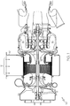
- FIG. 1 is a cross-sectional view of an aircraft APU 50 including an exemplary dual alloy turbine rotor according to an embodiment of the present invention.
- an inlet 10 receives ambient airflow 15, which is then directed to either a load compressor 12 or an engine compressor 14. Both compressors 12 and 14 are rotatably mounted on a shaft 18.
- the load compressor 12 draws in and compresses air for use as part of an environment control system (ECS) to cool and heat the aircraft interior.
- ECS environment control system
- the engine compressor 14 draws in and compresses air that will be used during combustion.
- a combustor 16 receives fuel from a fuel source and the compressed air from the engine compressor 14. Fuel combustion produces high temperature combustion gas that is provided to a two-stage power turbine assembly.
- the high temperature combustion gas flows along airfoil blades on a first-stage dual alloy turbine rotor 20, causing it to rotate. After passing the first-stage dual alloy turbine rotor 20, the air flows to airfoil blades on a second-stage dual alloy turbine 22.
- the first and second-stage dual alloy turbine rotors 20 and 22 are both mounted on the shaft 18. Rotation of the two-stage dual alloy turbine rotors generates work to drive the compressors 12 and 14, and to power other aircraft components.
- a dual-stage dual alloy turbine rotor is incorporated into the APU 50 depicted in FIG. 1
- the first-stage dual alloy turbine rotor 20 may be included in different multi-stage turbine assemblies that include three or more turbines in series.
- the architecture and materials for the first-stage dual alloy turbine rotor 20 enables its continued operational exposure to high temperature combustion gas flowing directly from the combustor 16.
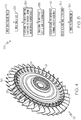
- FIGS. 2 through 4 provide different views of the dual alloy turbine rotor 20.
- the dual alloy turbine rotor 20 includes an annular blade ring 24 and a hub 26.
- the annular blade ring 24 is designed to withstand high combustion gas path temperatures (typically about 1800° Fahrenheit (°F) to about 3000°F) while the hub 26 is designed to withstand loading at more moderate temperatures.
- the blade ring comprises a first alloy that exhibits superior creep strength at the high combustion gas path temperatures.
- the blade ring 24 includes a ring portion 28 with an inner annular surface 29 ( FIG. 2 ) that defines an opening (not shown) for receiving the hub 26 as hereinafter described.
- the blade ring 24 includes a raised external surface portion 58 (e.g., FIG.
- the blade ring is an assembled blade ring.
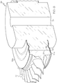
- the assembled blade ring comprises a plurality of individually cast airfoil blades 30 extending radially outwardly therefrom and formed into the ring portion 28.
- the individually cast blades 30 are formed into the ring portion of the blade ring with a blade braze joint (not shown) between each of the individually cast blades.
- the first alloy of the assembled blade ring comprises a single crystal alloy, a directionally solidified alloy, or an equi-axed alloy.
- the single crystal alloy comprises chemistry specially formulated for high temperature stress rupture and oxidation resistance.
- Suitable exemplary single crystal alloys include CMSX-3® and CMSX-4® alloys.
- the directionally solidified alloy comprises chemistry specially formulated for high temperature stress rupture and oxidation resistance.
- a suitable exemplary directionally solidified alloy includes MAR-M-247® alloy.
- An equi-axed alloy comprises chemistry specially formulated for high temperature stress rupture and oxidation resistance.
- Suitable exemplary equi-axed alloys include nickel-based superalloys such as Inconel IN738, MAR-M 247, etc.
- the hub 26 of the dual alloy turbine rotor 20 has a centrally-formed bore 34 and an outer peripheral surface 36.
- the hub 26 comprises a second alloy that is different from the first alloy.
- the hub includes a raised hub exterior surface portion 60 (e.g., FIG. 8 ) or a groove 61 ( FIG. 10 ) in an external surface portion for purposes as hereinafter described.
- the second alloy has a relatively high tensile strength as known in the art.
- the hub may be forged from a powdered metal alloy such as Rene 95, Astroloy PM, or other fine-grained alloys.
- a method 100 for manufacturing a dual alloy turbine rotor begins by providing the blade ring (step 110) and the hub (step 120) as described above.
- the blade ring 24 is an assembled blade ring comprising a first alloy.
- the first alloy comprises a single crystal alloy, a directionally solidified alloy, or an equi-axed alloy.
- the blade ring 24 provided in the method for manufacturing the dual alloy turbine rotor according to exemplary embodiments may alternatively comprise a conventional integrally cast unitary blade ring such as a cast unitary blade ring comprising an equi-axed alloy.
- the method 100 for manufacturing a dual alloy turbine rotor continues by positioning the hub within the opening (not shown) of the blade ring to define an interface 54 between the hub and the blade ring (step 130).
- the interface 54 is between the outer peripheral surface 36 of the hub and the inner annular surface 29 of the blade ring.
- the outer peripheral surface 36 of the hub 26 faces the inner annular surface 29 of the blade ring 24.
- the interface comprises a non-contacting interface between the outer peripheral surface of the hub and the inner annular surface of the blade ring.
- the hub and blade ring are physically separated and do not contact, forming a gap 56 between the outer peripheral surface of the hub and the inner annular surface of the blade ring.
- the inner annular surface 29 of the blade ring 24 is spaced apart from the outer peripheral surface 36 of the hub 26 to define the gap 56.
- the gap that exists at the non-contacting interface at initial positioning (step 130) permits substantially stress-free vacuum sealing of the interface as hereinafter described, i.e., there is substantially no stress imposed on the blade ring during the vacuum sealing step.
- the size of the gap 56 decreases during the vacuum sealing step due to the higher coefficient of thermal expansion (CTE) of the hub relative to the blade ring.
- CTE coefficient of thermal expansion
- the radial gap is sized to accommodate potential growth differences due to coefficients of thermal expansion and thermal gradients.
- the interface comprises a contacting interface as a result of step 130, such that the outer peripheral surface of the hub is positioned in near full or full surface contact with the inner annular surface of the blade ring when the hub is disposed within the opening in the blade ring.
- the blade ring inner diameter is shaped to receive the outer circumferential surface of the hub in near full or full surface area contact at the blade ring-hub surface interface.
- the value of the thermal expansion may be predicted by methods as known in the art.
- the relative geometry of the blade ring will grow to a greater degree relative to the geometry of the hub that is made of the second alloy having a lower coefficient of thermal expansion, i.e., the step of vacuum sealing the interface results in a temperature increase causing the blade ring with the higher coefficient of thermal expansion to expand more than the hub that is less responsive to temperature changes.
- the contacting interface becomes looser forming the gap 56 and the gap stress reduction function remains, i.e., the gap substantially prevents stress to the blade ring during the vacuum sealing step.
- the interface may be a contacting or a non-contacting interface as a result of step 130.
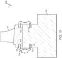
- method 100 continues with enclosing the interface with a pair of opposing diaphragms 52a, 52b, or 52c (step 135).
- the diaphragms comprise a metal material that can withstand hot isostatic pressing (HIP) processing temperatures of about 1000°C to about 1300°C, as hereinafter described.
- the metal material selected for the diaphragms may have a coefficient of thermal expansion that is intermediate the respective coefficient of thermal expansions for the first alloy and the second alloy.
- suitable metal material for the diaphragms include nickel-based and iron-based alloys, etc.
- the diaphragms may be configured in a number of different ways, as hereinafter described. As noted above, the diaphragms "enclose” the interface. As used herein, the term “enclose” refers to the diaphragms 52a, 52b, or 52c bridging the interface unlike the conventional "can” method that completely encloses the interface and the dual alloy components (the blade ring and hub). While diaphragms 52a, 52b, or 52c have been described, it is to be understood that diaphragms with different configurations may be used to enclose and vacuum seal the interface.
- the method 100 for manufacturing a dual alloy turbine rotor continues by vacuum sealing the interface (step 140).
- the vacuum sealing step comprises bonding the diaphragms to the blade ring 24 and to the hub 26 to complete formation of a rotor assembly.
- the interface between the blade ring and the hub is vacuum sealed with the pair of diaphragms.
- the diaphragms serve only to seal the interface and provide structural fuses that may deform either plastically or elastically to substantially prevent transferring of stress onto the blade ring.
- the diaphragms help withstand the deflection imposed by the CTE difference between the blade ring and the hub, allowing the blade ring to remain substantially stress-free during manufacture of the dual alloy turbine rotor 20.
- the step of vacuum sealing the interface comprises diffusion bonding the diaphragms 52a directly to the blade ring 24 and the hub 26 forming the rotor assembly 62a.
- the diaphragm 52a may be configured as a flexible, annular diaphragm that is substantially flat ( FIGS. 7 and 8 ) or flat ( FIG. 8 ) with a thickness of about 0.125 mm to about 3 mm.
- Diaphragm 52a may be referred to herein as a "shim-style diaphragm.” More particularly, the diaphragm 52a bridges the gap 56 at the interface 54 and may have a formed intermediate portion 64 (the concave intermediate portion 64 of FIG. 7 ) between a diaphragm first portion 66 and a diaphragm second portion 68. The interface may be vacuum sealed by diffusion bonding the diaphragm first portion 66 directly to the raised exterior surface portion 58 of the blade ring and the diaphragm second portion 68 directly to the raised hub exterior surface 60.
- the intermediate portion is disposed across the gap 56 at the interface and defines a free or unbounded space 71 between the diaphragm and the blade ring and hub respectively adjacent to and including the interface.
- the unbounded space permits the plastic and/or elastic deformation of the diaphragm during the vacuum sealing step.
- Direct diffusion bonding eliminates the need for braze material and brazing as hereinafter described. Diffusion bonding the diaphragm to the blade and to the hub applies only an axial compressive loading on the blade ring rather than a radial load as in the case of the conventional shrink-fit approach and no tensile hoop stress is present during the vacuum sealing step.
- TLP Transient Liquid Phase
- the step of vacuum sealing the interface comprises bonding the diaphragm 52a to the blade ring 24 and to the hub 26 by brazing.
- braze Known braze application techniques and braze materials may be used.
- the braze material has a melting temperature that is lower than a melting temperature of the blade ring and the hub.
- the braze material may be a braze foil, a braze paste, a plated layer, etc.
- the diaphragms 52a are disposed against the exterior surface of the blade ring and hub such that the intermediate portion (an unformed intermediate portion in FIG. 8 ) of each diaphragm bridges the gap 56 at the interface 54 and the diaphragm first portion 66 (e.g., FIG. 9A ) is brazed to the exterior surface portion of the blade ring outboard of the raised exterior portion 58 and the diaphragm second portion 68 (e.g., FIG. 9 ) is brazed to the exterior surface portion of the hub inboard of the raised hub exterior surface portion 60.
- the intermediate portion an unformed intermediate portion in FIG. 8
- the diaphragm first portion 66 e.g., FIG. 9A
- the diaphragm second portion 68 e.g., FIG. 9
- the diaphragm 52a defines opposing braze gaps 78 and 80 that are spaced away from the interface 54 and are configured to receive braze material 82 ( FIG. 9 ).
- the opposing raised exterior surfaces 58 and 60 serve as opposing braze stops that substantially prevent braze material 82 flow into the interface 54 from the opposing braze gaps 78 and 80.
- the opposing braze gaps are defined outboard of the braze stops.
- the opposing braze gaps 78 and 80 comprise a first braze gap 78 defined between the diaphragm first portion 66, the exterior surface of the blade ring 24, and the raised external surface portion 58 that serves as a braze stop and a second braze gap 80 is defined between the diaphragm second portion 68, the exterior surface of the hub 26, and the raised hub exterior surface portion 60 that also serves as a braze stop.
- the first and second braze gaps 78 and 80 are configured to receive the braze material 82 to form opposing braze joints.
- the braze stops are spaced away from the interface to substantially prevent the braze flow and braze contamination of the interface.
- the space 71 between the braze stops is substantially free of braze material.
- the unbounded space 71 permits the plastic and/or elastic deformation of the diaphragm during the vacuum sealing step.
- the spacing between the braze stops is also designed to ensure sufficient diaphragm length exists to absorb thermal growth differences between the blade ring and the hub, without exceeding the ductility of the diaphragm material or adversely loading the braze joints.
- a rotor assembly 62c comprises the blade ring 24, the hub 26, and diaphragm 52b.
- Diaphragm 52b is configured with a substantially U-shaped cross-section. The apex of the substantially U-shaped diaphragm may be convolute to provide predictable, controlled yielding.
- the "legs" of the substantially U-shaped diaphragm 52b may be pressed into the opposing grooves 59 and 61 in the blade ring and hub. The grooves serve to transfer load into the diaphragm without tensile loading of the braze joints in the blade ring.
- the substantially U-shaped diaphragm 52b is press fit at the internal diameter ("ID") of the grooves 59 and the external diameter ("OD") of the grooves 61 and defines the opposing braze gaps 78 and 80.
- the braze gaps are defined by the portion of each groove that is not occupied by the legs of the diaphragm.
- the braze gaps 78 and 80 receive braze material to braze the diaphragms to the blade ring and hub to form the rotor assembly 62c.
- the opposing braze gaps are configured to receive braze material to form the braze joints and are spaced away from the interface so as to substantially prevent braze contamination of the interface.
- the convolute portion of the diaphragm 52b serves as a flex zone, the flex zone being the annular region between raised external surface portion 58 and the raised hub exterior surface portion 60.
- a rotor assembly 62d comprises the blade ring 24, the hub 26, and diaphragm 52c.
- Diaphragm 52c may be configured as a two-piece fabricated spring assembly ("referred to herein as a "thermal spring diaphragm"), with an outer spring portion 84 and an inner spring portion 86.
- the spring portions each comprise a relatively flat annular portion 87 and a relatively thin, relatively long cylindrical flange 88 with an end portion 89 to facilitate joining of the end portions to form the diaphragm 52c.
- the outer and inner spring portions 84 and 86 may be fabricated separately and their respective end portions 89 brazed or welded together to form the diaphragm 52c.
- the diaphragms may be bonded to the blade ring and to the hub by brazing in the same manner as described above for diaphragms 52a ( FIGS. 8 and 9 ).
- the outer spring portion 84 is brazed to the exterior surface portion of the blade ring outboard of the raised exterior portion 58 and the inner spring portion 86 is brazed to the exterior surface portion of the hub inboard of the raised hub exterior surface portion 60.
- the diaphragm 52c defines opposing braze gaps 78 and 80 that are spaced away from the interface 54 and are configured to receive braze material 82 (not shown in FIG. 11 ).
- the opposing raised exterior surfaces 58 and 60 serve as opposing braze stops that substantially prevent braze material 82 flow into the interface 54 from the opposing braze gaps 78 and 80.
- the opposing braze gaps are defined outboard of the braze stops.
- the opposing braze gaps 78 and 80 comprise a first braze gap 78 defined between an exterior surface of the blade ring 24 and the raised external surface portion 58 that serves as a braze stop and a second braze gap 80 is defined between the exterior surface of the hub 26, and the raised hub exterior surface portion 60 that also serves as a braze stop.
- the first and second braze gaps 78 and 80 are configured to receive the braze material 82 to form opposing braze joints. While vacuum sealing by diffusion bonding, TLP bonding, and brazing have been described, diaphragms 52a, 52b, or 52c may alternatively or additionally be bonded to the blade ring and hub by electron beam welding.
- an upper spring portion 184 of a diaphragm 52d may be integrally machined as one piece with the blade ring 24 and a lower spring portion 186 integrally machined as one piece with the hub 26.
- End portions 189 of the top and bottom spring portions of the diaphragm may be brazed together to vacuum seal the interface between the hub and the blade ring.
- the gap 56 is defined at the interface between the end portions 189.
- the gap between the blade ring and hub results in a loose fit between the blade ring and the hub in rotor assembly 62e. Stress at the joint between the outer and inner spring portions can be minimized and tuned by varying the thickness and length of the spring portions. While vacuum sealing by brazing end portions 189 together has been described for rotor assembly 62e of FIG. 12 , end portions 189 may alternatively or additionally be bonded together by electron beam welding.
- the method 100 for manufacturing a dual alloy turbine rotor continues by bonding the blade ring to the hub after the vacuum sealing step (step 150).
- the blade ring may be bonded to the hub by hot isostatic pressing of the rotor assembly.
- Hot isostatic pressing is a process in which pressure is applied equally in all directions through an inert gas in a pressure vessel. Hot isostatic pressing may be performed at a hot isostatic pressing temperature and pressure to effect metallurgical bonding of the blade ring to the hub.
- the HIP process closes the gap formed at the positioning step (step 130) or the gap formed during the vacuum sealing step such that the outer peripheral surface of the hub in the dual alloy turbine rotor is substantially flush against the blade ring inner annular surface.
- the HIP process may be performed at a processing temperature in a range of about 1000° C to about 1300° C and may be performed at a pressure in a range of about 1 ksi to about 25 ksi for a time period of about 1 to about 10 hours.
- the HIP processing temperature and pressure may be higher or lower and the HIP processing time may be shorter or longer.
- the HIP process is generally known in the art.
- the method 100 for manufacturing a dual alloy turbine rotor may further comprise the step of removing the diaphragm after the bonding step 150 (step 160).
- the diaphragm may be removed by turning, milling, grinding, polishing, and/or other known methods.
- the dual alloy turbine rotor may undergo further processing including a finishing treatment. Finishing treatments may include, for example, aging, solutioning, annealing, quenching, peening, polishing, or coatings, or the like. If necessary, the dual alloy turbine rotor may be machined to final specifications. In some exemplary embodiments, no finishing treatments are necessary. Although such treatments are referred to here as a "finishing" treatment, such treatments may be used at other times.
- the dual alloy turbine rotors manufactured in accordance with exemplary embodiments as described herein include assembled blade rings that remain substantially stress-free during dual alloy turbine rotor manufacture, thereby substantially preventing their fracture during manufacture.
- the assembled blade rings may therefore include single crystal, directionally solidified, or equi-axed alloy blade rings.
Landscapes
- Engineering & Computer Science (AREA)
- Mechanical Engineering (AREA)
- General Engineering & Computer Science (AREA)
- Ceramic Engineering (AREA)
- Turbine Rotor Nozzle Sealing (AREA)
Applications Claiming Priority (2)
| Application Number | Priority Date | Filing Date | Title |
|---|---|---|---|
| US14/297,406 US9724780B2 (en) | 2014-06-05 | 2014-06-05 | Dual alloy turbine rotors and methods for manufacturing the same |
| EP15167774.7A EP2952687B1 (de) | 2014-06-05 | 2015-05-14 | Doppellegierung-turbinenrotor und verfahren zur herstellung davon |
Related Parent Applications (2)
| Application Number | Title | Priority Date | Filing Date |
|---|---|---|---|
| EP15167774.7A Division-Into EP2952687B1 (de) | 2014-06-05 | 2015-05-14 | Doppellegierung-turbinenrotor und verfahren zur herstellung davon |
| EP15167774.7A Division EP2952687B1 (de) | 2014-06-05 | 2015-05-14 | Doppellegierung-turbinenrotor und verfahren zur herstellung davon |
Publications (1)
| Publication Number | Publication Date |
|---|---|
| EP3617455A1 true EP3617455A1 (de) | 2020-03-04 |
Family
ID=53188902
Family Applications (2)
| Application Number | Title | Priority Date | Filing Date |
|---|---|---|---|
| EP19202307.5A Pending EP3617455A1 (de) | 2014-06-05 | 2015-05-14 | Doppellegierung-turbinenrotor und verfahren zur herstellung davon |
| EP15167774.7A Active EP2952687B1 (de) | 2014-06-05 | 2015-05-14 | Doppellegierung-turbinenrotor und verfahren zur herstellung davon |
Family Applications After (1)
| Application Number | Title | Priority Date | Filing Date |
|---|---|---|---|
| EP15167774.7A Active EP2952687B1 (de) | 2014-06-05 | 2015-05-14 | Doppellegierung-turbinenrotor und verfahren zur herstellung davon |
Country Status (2)
| Country | Link |
|---|---|
| US (2) | US9724780B2 (de) |
| EP (2) | EP3617455A1 (de) |
Families Citing this family (10)
| Publication number | Priority date | Publication date | Assignee | Title |
|---|---|---|---|---|
| US10584721B2 (en) * | 2013-02-27 | 2020-03-10 | Dresser-Rand Company | Method of construction for internally cooled diaphragms for centrifugal compressor |
| US9938834B2 (en) | 2015-04-30 | 2018-04-10 | Honeywell International Inc. | Bladed gas turbine engine rotors having deposited transition rings and methods for the manufacture thereof |
| US10294804B2 (en) * | 2015-08-11 | 2019-05-21 | Honeywell International Inc. | Dual alloy gas turbine engine rotors and methods for the manufacture thereof |
| US10036254B2 (en) | 2015-11-12 | 2018-07-31 | Honeywell International Inc. | Dual alloy bladed rotors suitable for usage in gas turbine engines and methods for the manufacture thereof |
| US20180104765A1 (en) * | 2016-10-13 | 2018-04-19 | United Technologies Corporation | Hybrid component and method of making |
| EP3315239B1 (de) * | 2016-10-28 | 2019-12-25 | Honeywell International Inc. | Verfahren zur herstellung von zur verwendung in gastubrinenmotoren geeignete, doppeltlegierte beschaufelte rotoren |
| US10751843B2 (en) | 2017-06-30 | 2020-08-25 | Honeywell International Inc. | Turbine wheels, turbine engines including the same, and methods of fabricating turbine wheels with improved bond line geometry |
| RU2687855C1 (ru) * | 2018-04-23 | 2019-05-16 | Научно-производственная ассоциация "Технопарк Авиационных Технологий" | Способ изготовления моноколеса газотурбинного двигателя |
| US11549374B2 (en) | 2020-02-18 | 2023-01-10 | Raytheon Technologies Corporation | Gas turbine rotor component and method of manufacture |
| CN117415573A (zh) * | 2023-09-06 | 2024-01-19 | 深圳市万泽中南研究院有限公司 | 热等静压扩散连接制备双合金整体叶盘的方法 |
Citations (4)
| Publication number | Priority date | Publication date | Assignee | Title |
|---|---|---|---|---|
| EP0042744A1 (de) * | 1980-06-23 | 1981-12-30 | The Garrett Corporation | Turbinenräder aus zwei Legierungen |
| US4796343A (en) * | 1986-08-01 | 1989-01-10 | Rolls-Royce Plc | Gas turbine engine rotor assembly |
| US20040117961A1 (en) * | 2002-12-18 | 2004-06-24 | Honeywell International Inc. | Spun metal form used to manufacture dual alloy turbine wheel |
| EP2047945A1 (de) * | 2007-10-09 | 2009-04-15 | Hamilton Sundstrand Corporation | Herstellungsverfahren für einen Turbinenrotor und entsprechender Turbinenrotor |
Family Cites Families (52)
| Publication number | Priority date | Publication date | Assignee | Title |
|---|---|---|---|---|
| US655414A (en) | 1900-03-05 | 1900-08-07 | Charles Algernon Parsons | Steam-turbine ring of blades. |
| US1621002A (en) | 1924-04-09 | 1927-03-15 | Allis Chalmers Mfg Co | Method of manufacturing turbines |
| US2392281A (en) * | 1941-07-10 | 1946-01-01 | Allis Chalmers Mfg Co | Method of making welded blade structures |
| US2347034A (en) | 1942-03-28 | 1944-04-18 | Gen Electric | Turbine bucket wheel and the like |
| US2380276A (en) | 1944-01-03 | 1945-07-10 | Gen Electric | Welded structure |
| NL64042C (de) | 1944-02-25 | |||
| GB599475A (en) * | 1944-09-21 | 1948-03-12 | British Thomson Houston Co Ltd | Improvements in and relating to turbine bucket wheels and the like |
| US3083446A (en) * | 1950-06-14 | 1963-04-02 | Stalker Corp | Rotor construction |
| US3292245A (en) | 1962-02-20 | 1966-12-20 | Demag Ag | Process and apparatus for making rotors |
| US4084922A (en) | 1976-12-27 | 1978-04-18 | Electric Power Research Institute, Inc. | Turbine rotor with pin mounted ceramic turbine blades |
| US4152816A (en) * | 1977-06-06 | 1979-05-08 | General Motors Corporation | Method of manufacturing a hybrid turbine rotor |
| US4581300A (en) * | 1980-06-23 | 1986-04-08 | The Garrett Corporation | Dual alloy turbine wheels |
| GB2109274A (en) * | 1981-11-13 | 1983-06-02 | Rolls Royce | Gas turbine engine rotor assembly |
| US4447188A (en) | 1982-04-29 | 1984-05-08 | Williams International Corporation | Cooled turbine wheel |
| US4587700A (en) | 1984-06-08 | 1986-05-13 | The Garrett Corporation | Method for manufacturing a dual alloy cooled turbine wheel |
| CH667611A5 (de) | 1985-02-28 | 1988-10-31 | Bbc Brown Boveri & Cie | Verfahren zum herstellen eines regelrades fuer den hochdruckrotor einer dampfturbine. |
| US4784573A (en) | 1987-08-17 | 1988-11-15 | United Technologies Corporation | Turbine blade attachment |
| US4784572A (en) | 1987-10-14 | 1988-11-15 | United Technologies Corporation | Circumferentially bonded rotor |
| US4904159A (en) * | 1988-07-18 | 1990-02-27 | Suburbia Systems, Inc. | Pump impeller |
| GB2237758B (en) | 1989-11-07 | 1992-10-21 | Rolls Royce Plc | Rotor assembly and method of manufacture |
| CA2030427A1 (en) | 1989-12-19 | 1991-06-20 | Jonathan S. Stinson | Method of enhancing bond joint structural integrity of spray cast articles |
| US5113583A (en) * | 1990-09-14 | 1992-05-19 | United Technologies Corporation | Integrally bladed rotor fabrication |
| US5122033A (en) | 1990-11-16 | 1992-06-16 | Paul Marius A | Turbine blade unit |
| GB9112043D0 (en) | 1991-06-05 | 1991-07-24 | Sec Dep For The Defence | A titanium compressor blade having a wear resistant portion |
| US5292385A (en) | 1991-12-18 | 1994-03-08 | Alliedsignal Inc. | Turbine rotor having improved rim durability |
| US5277548A (en) * | 1991-12-31 | 1994-01-11 | United Technologies Corporation | Non-integral rotor blade platform |
| US5273708A (en) * | 1992-06-23 | 1993-12-28 | Howmet Corporation | Method of making a dual alloy article |
| US5316202A (en) | 1992-10-14 | 1994-05-31 | General Electric Company | In-jig assembly bond fixture for manufacturing composite components |
| US5587700A (en) | 1994-08-29 | 1996-12-24 | Williams; Thomas | Portable security alarm unit |
| US5593085A (en) * | 1995-03-22 | 1997-01-14 | Solar Turbines Incorporated | Method of manufacturing an impeller assembly |
| US5755031A (en) | 1996-11-12 | 1998-05-26 | United Technologies Corporation | Method for attaching a rotor blade to an integrally bladed rotor |
| GB9713395D0 (en) | 1997-06-25 | 1997-08-27 | Rolls Royce Plc | Improvements in or relating to the friction welding of components |
| US6061886A (en) | 1997-07-11 | 2000-05-16 | Honda Giken Kogyo Kabushiki Kaisha | Turbine blade fitting apparatus and fitting method |
| CA2307471A1 (en) | 1997-10-27 | 1999-05-06 | Siemens Westinghouse Power Corporation | Method of bonding cast superalloys |
| US6508000B2 (en) | 2001-02-08 | 2003-01-21 | Siemens Westinghouse Power Corporation | Transient liquid phase bonding repair for advanced turbine blades and vanes |
| US6591613B2 (en) | 2001-03-15 | 2003-07-15 | General Electric Co. | Methods for operating gas turbine engines |
| US6946096B2 (en) | 2002-05-03 | 2005-09-20 | Honeywell International, Inc. | Use of powder metal sintering/diffusion bonding to enable applying silicon carbide or rhenium alloys to face seal rotors |
| US6666653B1 (en) | 2002-05-30 | 2003-12-23 | General Electric Company | Inertia welding of blades to rotors |
| US6969240B2 (en) | 2003-08-01 | 2005-11-29 | Honeywell International Inc. | Integral turbine composed of a cast single crystal blade ring diffusion bonded to a high strength disk |
| US6916150B2 (en) | 2003-11-26 | 2005-07-12 | Siemens Westinghouse Power Corporation | Cooling system for a tip of a turbine blade |
| GB0408497D0 (en) | 2004-04-16 | 2004-05-19 | Rolls Royce Plc | Turbine blisk |
| US20060239825A1 (en) * | 2005-04-21 | 2006-10-26 | Honeywell International Inc. | Bi-cast blade ring for multi-alloy turbine rotor |
| US7832986B2 (en) | 2007-03-07 | 2010-11-16 | Honeywell International Inc. | Multi-alloy turbine rotors and methods of manufacturing the rotors |
| US8262817B2 (en) | 2007-06-11 | 2012-09-11 | Honeywell International Inc. | First stage dual-alloy turbine wheel |
| FR2921409B1 (fr) * | 2007-09-25 | 2009-12-18 | Snecma | Clinquant pour aube de turbomachine. |
| US20090119919A1 (en) | 2007-11-12 | 2009-05-14 | Honeywell International, Inc. | Components for gas turbine engines and methods for manufacturing components for gas turbine engines |
| US8206117B2 (en) | 2007-12-19 | 2012-06-26 | Honeywell International Inc. | Turbine components and methods of manufacturing turbine components |
| JP5916377B2 (ja) * | 2011-12-27 | 2016-05-11 | 三菱重工業株式会社 | 過給機用タービン及び過給機の組立方法 |
| US8408446B1 (en) * | 2012-02-13 | 2013-04-02 | Honeywell International Inc. | Methods and tooling assemblies for the manufacture of metallurgically-consolidated turbine engine components |
| EP2679770A1 (de) * | 2012-06-26 | 2014-01-01 | Siemens Aktiengesellschaft | Dichtstreifen für Turbinenschaufelplattform |
| US9212562B2 (en) * | 2012-07-18 | 2015-12-15 | United Technologies Corporation | Bayoneted anti-rotation turbine seals |
| WO2014168743A1 (en) * | 2013-04-12 | 2014-10-16 | United Technologies Corporation | Integrally bladed rotor |
-
2014
- 2014-06-05 US US14/297,406 patent/US9724780B2/en active Active
-
2015
- 2015-05-14 EP EP19202307.5A patent/EP3617455A1/de active Pending
- 2015-05-14 EP EP15167774.7A patent/EP2952687B1/de active Active
-
2017
- 2017-07-13 US US15/648,577 patent/US10399176B2/en active Active
Patent Citations (4)
| Publication number | Priority date | Publication date | Assignee | Title |
|---|---|---|---|---|
| EP0042744A1 (de) * | 1980-06-23 | 1981-12-30 | The Garrett Corporation | Turbinenräder aus zwei Legierungen |
| US4796343A (en) * | 1986-08-01 | 1989-01-10 | Rolls-Royce Plc | Gas turbine engine rotor assembly |
| US20040117961A1 (en) * | 2002-12-18 | 2004-06-24 | Honeywell International Inc. | Spun metal form used to manufacture dual alloy turbine wheel |
| EP2047945A1 (de) * | 2007-10-09 | 2009-04-15 | Hamilton Sundstrand Corporation | Herstellungsverfahren für einen Turbinenrotor und entsprechender Turbinenrotor |
Also Published As
| Publication number | Publication date |
|---|---|
| US20150354379A1 (en) | 2015-12-10 |
| EP2952687B1 (de) | 2019-11-20 |
| US9724780B2 (en) | 2017-08-08 |
| EP2952687A3 (de) | 2015-12-30 |
| EP2952687A2 (de) | 2015-12-09 |
| US10399176B2 (en) | 2019-09-03 |
| US20170304929A1 (en) | 2017-10-26 |
Similar Documents
| Publication | Publication Date | Title |
|---|---|---|
| US10399176B2 (en) | Dual alloy turbine rotors and methods for manufacturing the same | |
| US5735046A (en) | Method of manufacturing a multiproperty rotor disk | |
| US8408446B1 (en) | Methods and tooling assemblies for the manufacture of metallurgically-consolidated turbine engine components | |
| US5732468A (en) | Method for bonding a turbine engine vane segment | |
| US4529452A (en) | Process for fabricating multi-alloy components | |
| US9498850B2 (en) | Structural case for aircraft gas turbine engine | |
| EP2359975B1 (de) | Schweißverfahren und damit geformte Komponente | |
| US11788467B2 (en) | Bladed rotor wheel | |
| US9194252B2 (en) | Turbine frame fairing for a gas turbine engine | |
| US20150247409A1 (en) | Axially-split radial turbines | |
| US9938834B2 (en) | Bladed gas turbine engine rotors having deposited transition rings and methods for the manufacture thereof | |
| US20100172761A1 (en) | Method of fabricating a turbomachine compressor drum | |
| EP3000556A1 (de) | Ummantelte verbundene turbinenrotoren und verfahren zur herstellung davon | |
| US10767496B2 (en) | Turbine blade assembly with mounted platform | |
| US20190184489A1 (en) | Method for joining components and device | |
| US20150211372A1 (en) | Hot isostatic pressing to heal weld cracks | |
| US10294804B2 (en) | Dual alloy gas turbine engine rotors and methods for the manufacture thereof | |
| US20110100961A1 (en) | Welding process for producing rotating turbomachinery | |
| US20110142653A1 (en) | Two piece impeller | |
| US9914182B2 (en) | Methods for fabricating gas turbine engine components using a stepped transient liquid phase joining process | |
| US20250334130A1 (en) | Radial turbine rotor with additive layer manufactured components | |
| US20110150658A1 (en) | Rotating hardware and process therefor |
Legal Events
| Date | Code | Title | Description |
|---|---|---|---|
| PUAI | Public reference made under article 153(3) epc to a published international application that has entered the european phase |
Free format text: ORIGINAL CODE: 0009012 |
|
| STAA | Information on the status of an ep patent application or granted ep patent |
Free format text: STATUS: REQUEST FOR EXAMINATION WAS MADE |
|
| 17P | Request for examination filed |
Effective date: 20191009 |
|
| AC | Divisional application: reference to earlier application |
Ref document number: 2952687 Country of ref document: EP Kind code of ref document: P |
|
| AK | Designated contracting states |
Kind code of ref document: A1 Designated state(s): AL AT BE BG CH CY CZ DE DK EE ES FI FR GB GR HR HU IE IS IT LI LT LU LV MC MK MT NL NO PL PT RO RS SE SI SK SM TR |
|
| RAP3 | Party data changed (applicant data changed or rights of an application transferred) |
Owner name: HONEYWELL INTERNATIONAL INC. |
|
| STAA | Information on the status of an ep patent application or granted ep patent |
Free format text: STATUS: EXAMINATION IS IN PROGRESS |
|
| 17Q | First examination report despatched |
Effective date: 20220518 |
|
| RAP3 | Party data changed (applicant data changed or rights of an application transferred) |
Owner name: HONEYWELL INTERNATIONAL INC. |
|
| RIN1 | Information on inventor provided before grant (corrected) |
Inventor name: SMOKE, JASON Inventor name: MITTENDORF, DON Inventor name: JAN, DAVID K. Inventor name: MINER, AMENDINE |
|
| P01 | Opt-out of the competence of the unified patent court (upc) registered |
Effective date: 20230421 |
|
| GRAP | Despatch of communication of intention to grant a patent |
Free format text: ORIGINAL CODE: EPIDOSNIGR1 |
|
| STAA | Information on the status of an ep patent application or granted ep patent |
Free format text: STATUS: GRANT OF PATENT IS INTENDED |