EP3617078A1 - Binder, and binder packet - Google Patents
Binder, and binder packet Download PDFInfo
- Publication number
- EP3617078A1 EP3617078A1 EP18790451.1A EP18790451A EP3617078A1 EP 3617078 A1 EP3617078 A1 EP 3617078A1 EP 18790451 A EP18790451 A EP 18790451A EP 3617078 A1 EP3617078 A1 EP 3617078A1
- Authority
- EP
- European Patent Office
- Prior art keywords
- binder
- base member
- surface member
- leg portions
- bound
- Prior art date
- Legal status (The legal status is an assumption and is not a legal conclusion. Google has not performed a legal analysis and makes no representation as to the accuracy of the status listed.)
- Withdrawn
Links
- 239000011230 binding agent Substances 0.000 title claims abstract description 140
- 239000004033 plastic Substances 0.000 claims description 4
- 230000008878 coupling Effects 0.000 description 14
- 238000010168 coupling process Methods 0.000 description 14
- 238000005859 coupling reaction Methods 0.000 description 14
- 230000000694 effects Effects 0.000 description 10
- 230000004048 modification Effects 0.000 description 9
- 238000012986 modification Methods 0.000 description 9
- 238000003780 insertion Methods 0.000 description 8
- 230000037431 insertion Effects 0.000 description 8
- 238000006073 displacement reaction Methods 0.000 description 5
- 230000004308 accommodation Effects 0.000 description 4
- 230000002265 prevention Effects 0.000 description 4
- 230000003139 buffering effect Effects 0.000 description 3
- 238000010008 shearing Methods 0.000 description 2
- 238000005452 bending Methods 0.000 description 1
- 239000011248 coating agent Substances 0.000 description 1
- 238000000576 coating method Methods 0.000 description 1
- 230000003247 decreasing effect Effects 0.000 description 1
- 238000000465 moulding Methods 0.000 description 1
- 230000036964 tight binding Effects 0.000 description 1
Images





Classifications
-
- B—PERFORMING OPERATIONS; TRANSPORTING
- B65—CONVEYING; PACKING; STORING; HANDLING THIN OR FILAMENTARY MATERIAL
- B65B—MACHINES, APPARATUS OR DEVICES FOR, OR METHODS OF, PACKAGING ARTICLES OR MATERIALS; UNPACKING
- B65B13/00—Bundling articles
- B65B13/18—Details of, or auxiliary devices used in, bundling machines or bundling tools
- B65B13/24—Securing ends of binding material
- B65B13/34—Securing ends of binding material by applying separate securing members, e.g. deformable clips
- B65B13/345—Hand tools
-
- B—PERFORMING OPERATIONS; TRANSPORTING
- B65—CONVEYING; PACKING; STORING; HANDLING THIN OR FILAMENTARY MATERIAL
- B65B—MACHINES, APPARATUS OR DEVICES FOR, OR METHODS OF, PACKAGING ARTICLES OR MATERIALS; UNPACKING
- B65B13/00—Bundling articles
- B65B13/18—Details of, or auxiliary devices used in, bundling machines or bundling tools
- B65B13/185—Details of tools
-
- B—PERFORMING OPERATIONS; TRANSPORTING
- B65—CONVEYING; PACKING; STORING; HANDLING THIN OR FILAMENTARY MATERIAL
- B65B—MACHINES, APPARATUS OR DEVICES FOR, OR METHODS OF, PACKAGING ARTICLES OR MATERIALS; UNPACKING
- B65B13/00—Bundling articles
- B65B13/02—Applying and securing binding material around articles or groups of articles, e.g. using strings, wires, strips, bands or tapes
- B65B13/025—Hand-held tools
-
- B—PERFORMING OPERATIONS; TRANSPORTING
- B65—CONVEYING; PACKING; STORING; HANDLING THIN OR FILAMENTARY MATERIAL
- B65B—MACHINES, APPARATUS OR DEVICES FOR, OR METHODS OF, PACKAGING ARTICLES OR MATERIALS; UNPACKING
- B65B27/00—Bundling particular articles presenting special problems using string, wire, or narrow tape or band; Baling fibrous material, e.g. peat, not otherwise provided for
-
- B—PERFORMING OPERATIONS; TRANSPORTING
- B65—CONVEYING; PACKING; STORING; HANDLING THIN OR FILAMENTARY MATERIAL
- B65B—MACHINES, APPARATUS OR DEVICES FOR, OR METHODS OF, PACKAGING ARTICLES OR MATERIALS; UNPACKING
- B65B51/00—Devices for, or methods of, sealing or securing package folds or closures; Devices for gathering or twisting wrappers, or necks of bags
- B65B51/04—Applying separate sealing or securing members, e.g. clips
-
- B—PERFORMING OPERATIONS; TRANSPORTING
- B65—CONVEYING; PACKING; STORING; HANDLING THIN OR FILAMENTARY MATERIAL
- B65B—MACHINES, APPARATUS OR DEVICES FOR, OR METHODS OF, PACKAGING ARTICLES OR MATERIALS; UNPACKING
- B65B51/00—Devices for, or methods of, sealing or securing package folds or closures; Devices for gathering or twisting wrappers, or necks of bags
- B65B51/04—Applying separate sealing or securing members, e.g. clips
- B65B51/08—Applying binding material, e.g. to twisted bag necks
-
- B—PERFORMING OPERATIONS; TRANSPORTING
- B65—CONVEYING; PACKING; STORING; HANDLING THIN OR FILAMENTARY MATERIAL
- B65B—MACHINES, APPARATUS OR DEVICES FOR, OR METHODS OF, PACKAGING ARTICLES OR MATERIALS; UNPACKING
- B65B67/00—Apparatus or devices facilitating manual packaging operations; Sack holders
- B65B67/02—Packaging of articles or materials in containers
-
- B—PERFORMING OPERATIONS; TRANSPORTING
- B65—CONVEYING; PACKING; STORING; HANDLING THIN OR FILAMENTARY MATERIAL
- B65B—MACHINES, APPARATUS OR DEVICES FOR, OR METHODS OF, PACKAGING ARTICLES OR MATERIALS; UNPACKING
- B65B27/00—Bundling particular articles presenting special problems using string, wire, or narrow tape or band; Baling fibrous material, e.g. peat, not otherwise provided for
- B65B27/06—Bundling coils of wire or like annular objects
Definitions
- the present invention relates to a binder used when binding a harness, a bag mouth, a field wire, an attraction string and the like.
- Patent Literature 1 discloses a plastic binding clip having a U-shape. This binding clip is configured such that a bound member can be bound by inserting the bound member between leg portions of the binding clip and bending the leg portions inward.
- Patent Literature 1 JP-A-2004-10125
- the above-described conventional binder is required to bind so tightly as to bite into the bound member in order to avoid displacement of the binder. Therefore, the bound member may be damaged by such tight binding.
- a first object of the present invention is to provide a binder capable of performing stable binding while reducing displacement even if binding strength is not as strong as causing damage to a bound member.
- the above-described conventional binder may cause damage by hitting other members or may be broken by an impact from other members.
- a second object of the present invention is to provide a binder that is less likely to damage other members or be broken even when used at a location where vibration occurs.
- the present invention has been made in view of the above-described problems, and provides a binder configured to bind a bound member by being struck out from a binding machine.
- the binder includes a substantially U-shaped base member that is plastically deformable, and a surface member that is provided on a surface of the base member.
- the present invention is as described above, and the surface member is provided on the surface of the substantially U-shaped base member that is plastically deformable. According to such a configuration, as the surface member is provided on an inner surface and/or an outer surface of the base member, the effects such as stable binding and/or prevention of damage can be obtained.
- the frictional resistance at a position in contact with the bound member can be improved, so that the holding force of the binder can be increased. Therefore, binding can be stably performed without displacement of the binder even if the binding strength is appropriate not as strong as causing damage to the bound member. Further, the effect of reducing impact when the binder hits other members can be expected.
- the surface member is provided on the outer surface of the base member, the buffering property at a position hitting other members can be improved. Therefore, even when the binder is used at a location where vibration occurs, damage to other members can be reduced and breakage is less likely to occur. Further, since the impact at hitting to other members is alleviated, the effect of preventing the binder from falling off by the impact can also be expected.
- a binder 41 according to the present embodiment is used by being loaded into a binding machine 10 as shown in Fig. 1 , for example.
- the binding machine 10 binds a bound member 50 by closing an opening 41c of the binder 41.
- the binding machine 10 is used, for example, for binding a harness, a bag mouth, a field wire or an attraction string.
- a handheld type binding machine 10 will be described as an example.
- the binder 41 according to the present embodiment can be used not only for the handheld type binding machine 10 but also for a stationary type binding machine.
- the binding machine 10 is covered with a housing 11, and includes a motor accommodation portion 12, a grip portion 13 and an output portion 15.
- the motor accommodation portion 12 is provided at a rear portion of the binding machine 10, and a power source connection portion 12a which connects an external power source is provided at a rear end portion thereof.
- a voltage supply from the power source connection portion 12a By receiving a voltage supply from the power source connection portion 12a, the binding machine 10 can perform various operations such as striking out the binder 41.
- a cord which connects to an AC [0] power source may be connected to the power source connection portion 12a, or a harness which connects to a rechargeable battery may be attached thereto.
- the binding machine 10 according to the present embodiment is of an electric type, the present invention is not limited thereto, and the binding machine 10 may be of a compressed air type. When the binding machine 10 is of the compressed air type, a connection portion which receives supply of compressed air may be provided instead of the power source connection portion 12a.
- a motor and a control portion are housed in the motor accommodation portion 12, so that driving of a driver 25 (described below) can be controlled.
- the grip portion 13 is a portion to be gripped by a user when the binding machine 10 is used.
- the grip portion 13 is provided in an intermediate portion of the housing 11, and is formed in a constricted shape so as to be easily gripped by the user.
- An operation portion 14 is provided on an obliquely front side of the grip portion 13 at a position that can be operated with an index finger when the grip portion 13 is gripped.
- the operation portion 14 can be manually operated to perform a binding operation.
- the operation portion 13 is a swing member having a trigger shape in the present embodiment.
- the driver 25 (described below) is activated when the operation portion 14 is pulled.
- the output portion 15 is provided in the vicinity of a tip end of the binding machine 10. At a tip end of the output portion 15, a protrusion forming portion 17 protrudes in a substantially L-shape, and an insertion opening 16 into which the bound member 50 is inserted is opened inside the protrusion forming portion 17.
- the driver 25 is housed in the output portion 15.
- a magazine portion 35 is provided on a side portion of the output portion 15.
- the protrusion forming portion 17 is formed as a part of the housing 11 or is integrally fixed to the housing 11.
- a clincher 18 is provided on an inner surface of the protrusion forming portion 17 at a position where a tip end of the driver 25 (described below) is received. As shown in Fig. 7A , the clincher 18 and the driver 25 stand by at positions apart from each other before the binder 41 is struck out, and the insertion opening 16 is provided between the clincher 18 and the driver 25.
- the binding machine 10 according to the present embodiment performs binding by striking out the binder 41 toward the insertion opening 16.
- the clincher 18 is configured to clinch leg portions 41 a of the binder 41 struck out by the driver 25 to complete the binding. Specifically, the clincher 18 is a plate against which the binder 41 struck out by the driver 25 is pressed. A groove for guiding the leg portions 41a of the binder 41 is formed on a surface of the clincher 18, and the leg portions 41a of the binder 41 pressed against the clincher 18 are bent inward (clinched) along the groove.
- the driver 25 is an elongated plate that performs a rectilinear motion by a drive mechanism (not shown) in order to strike out the binder 41 toward the insertion opening 16. As shown in Figs. 7A and 7B , the driver 25 is slidably guided inside the housing 11, and can reciprocate in a striking direction of the binder 41. The driver 25 presses the struck binder 41 against the clincher 18 to bend the leg portions 41a of the binder 41, thereby closing the opening 41c to complete the binding.
- the magazine portion 35 is configured to load a plurality of binders 41.
- the binding machine 10 uses a binder packet 40 as shown in Fig. 3C , and the magazine portion 35 can be loaded thereon such a binder packet 40.
- the binder packet 40 is configured by coupling a plurality of binders 41 to each other.
- each binder 41 includes a pair of leg portions 41a and a connection portion 41b connecting the pair of leg portions 41a to be formed in a substantially U-shape.
- coupling portions 44 for coupling adjacent binders 41 are provided on front and back surfaces of the connection portion 41b.
- the coupling portion 44 is formed to be weaker and thinner than the other portions so as to be easily broken.
- the opening 41c which holds the bound member 50 is formed between the pair of leg portions 41a.
- the leg portions 41a are plastically deformed as shown in Figs. 4A and 4B such that the bound member can be held and bound.
- the magazine portion 35 includes a rib 35a that enters between the leg portions 41a of the binder 41 (that is, the opening 41c).
- a groove 35b that guides the connection portion 41b of the binder 41 is formed so as to face a tip end of the rib 35a.
- the magazine portion 35 is provided with a pusher 36 slidable along a longitudinal direction of the magazine portion 35.
- the pusher 36 is configured to bias the binder packet 40 loaded in the magazine portion 35 forward, and is always biased forward (in a direction of sending the binder 41 to a standby portion 37 (described below)) by a spring (not shown).
- the magazine portion 35 is connected to the side portion of the output portion 15, and is configured to guide the binder packet 40 inside the output portion 15.
- the standby portion 37 is provided which makes the binder 41 stand by in a state for being struck out.
- the standby portion 37 is provided between the driver 25 and the insertion opening 16, and the binder 41 standing by at the standby portion 37 is struck out by the driver 25 in a direction of the insertion opening 16.
- the binder packet 40 When the binder packet 40 is loaded in the magazine portion 35, as shown in Fig. 6 , the binder packet 40 is loaded so as to straddle the rib 35a, so that the connection portion 41b of the binder 41 passes through the groove 35b of the magazine portion 35. When the binder packet 40 is loaded in this manner, the binder packet 40 is biased by the pusher 36 in a direction toward the standby portion 37.
- the bound member 50 is first inserted into the insertion opening 16.
- the motor rotates and the diver 25 strikes out the binder 41 supplied to the standby portion 37 (see Fig. 7B ), and the leg portions 41a of the struck binder 41 are clinched by the clincher 18 to complete the binding.
- the binder 41 includes a substantially U-shaped base member 42 that is plastically deformable, and a surface member 43 provided on a surface of the base member 42.
- the base member 42 is a main body of the binder 41, and holds and binds the bound member 50 by plastic deformation. As described above, the base member 42 includes the pair of leg portions 41a, the connection portion 41b connecting the pair of leg portions 41a, and the coupling portions 44 which couples adjacent connection portions 41b.
- the surface member 43 is a thin portion provided on a part of the surface of the base member 42.
- the surface member 43 is formed integrally with the base member 42 by two-layer molding.
- the surface member 43 is not necessarily formed integrally with the base member 42.
- the surface member 43 may be adhered to the base member 42, or the surface member 43 may be provided by coating the base member 42, or the surface member 43 may be assembled to the base member 42.
- the base member 42 is formed of plastic, and the surface member 43 is formed of rubber. Therefore, a friction coefficient between the surface member 43 and the bound member 50 is larger than a friction coefficient between the base member 42 and the bound member 50. That is, the surface member 43 provides the effect of slip prevention.
- the surface member 43 has an elastic limit higher than that of the base member 42, so that the impact can be alleviated when the surface member 43 hits other members.
- the surface member 43 is provided on an inner side of the substantially U-shape of the base member 42, the surface member 43 comes into contact with the bound member 50 during binding.
- each binder 41 is coupled to other binders 41 on front and back surfaces thereof.
- the front and back surfaces (surfaces facing a coupling direction) of the binder 41 are not provided with the surface member 43.
- the surface member 43 is formed to be thinner than a thickness D (see Fig. 3C ) between the front and back surfaces of the binder 41, and does not protrude from the front and back surfaces of the binder 41. Therefore, when the binder 41 is struck out by the driver 25, the surface member 43 does not contact a sliding guide surface inside the housing 11, and the frictional resistance during striking is not increased. Accordingly, the binder 41 can be struck out smoothly. Even when the surface member 43 is provided, since the thickness of the binder 41 is not affected, the pitch for connecting the binders 41 is not required to be increased, so that the size of the binder packet 40 can be kept small.
- tip ends of the leg portions 41a of the binder 41 are not provided with the surface member 43. Therefore, the problem should not occur that the surface member 43 provided at tip ends of the leg portions 41a is peeled off due to friction when the leg portions 41a is clinched. In particular, as the surface member 43 is not provided at outer tip ends of the leg portions 41a, peeling of the surface member 43 during clinching can be prevented.
- the surface member 43 is provided in a substantially U-shape on an inner side of the base member 42.
- the present invention is not limited thereto.
- surface members 43 may be respectively provided at positions facing each other on inner sides of the pair of leg portions 41a.
- the surface members 43 may be provided while avoiding an inner side of the connection portion 41b.
- a smooth striking of the binder 41 can be realized while obtaining the effect of slip prevention by the surface member 43. That is, when the binder 41 is struck out, as shown in Fig. 7B , a shearing force is applied to the coupling portion 44 to break the coupling portion 44 by pressing the remaining binder packet 40 with the rib 35a while striking a leading binder 41 with the driver 25.
- the surface member 43 when the surface member 43 is provided on the inner side of the connection portion 41b as shown in Figs. 3A to 3C , the surface member 43 on the inner side of the connection portion 41b contacts the tip end of the rib 35a, so that the impact applied to the coupling portion 44 is alleviated by the surface member 43, and the instantaneous shearing force for breaking the coupling portion 44 is decreased. If the coupling portion 44 is harder to break due to a decrease in the instantaneous shear force, the striking speed may be slowed down, which causes poor binding, or the coupling portion 44 may be stretched by being slowly broken, resulting in generation of burrs.
- connection portion 41b if the surface member 43 is not provided on the inner side of the connection portion 41b, buffering due to the surface member 43 does not occur when the coupling portion 44 is broken, so that the connection portion 41b can be easily separated.
- the surface members 43 since the surface members 43 are provided on the inner side of the leg portions 41a that holds the bound member 50, the surface members 43 can sandwich the bound member 50 from both directions. Therefore, the effect of preventing the bound member 50 from slipping is sufficiently enhanced.
- the frictional resistance may be increased, which causes a sending failure.
- the surface member 43 is not provided on the inner side of the connection portion 41b serving as a contact portion with the rib 35a, an increase in the frictional resistance can be prevented, and the binder packet 40 can be reliably sent.
- the surface member 43 may be provided on the inner side of the connection portion 41b, and the surface member 43 may not be provided at positions facing each other on the inner sides of the pair of leg portions 41a. In such a configuration, since the surface member 43 is provided on the inner side of the connection portion 41b that hits the bound member 50 when the binder 41 is struck out, the bound member 50 can be buffered and protected at a portion where the load is applied most.
- the surface member 43 may be provided on an outer side of a substantially U-shape of the base member 42. By providing the surface member 43 on the outer side of the base member 42, the surface member 43 functions as a buffer when the binder 41 hits other members, so that breakage can be reduced or prevented.
- a shape of a surface of the surface member 43 may have various forms, and may be determined according to the using environment and purpose.
- the surface of the surface member 43 may be formed flat.
- the surface member 43 may be formed in a rib shape.
- the surface member 43 may be formed in a mountain shape in cross section.
- the surface member 43 may be formed in a concave shape in cross section.
- the surface member 43 may be formed to bulge in an R-shape in cross section.
- the surface member 43 may be provided on both inner and outer sides of the base member 42.
- the surface member 43 may be provided so as to coat the base member 42.
- the binder 41 includes an elastically deformable surface member 43 on the surface of the substantially U-shaped base member 42 that is plastically deformable. According to such a configuration, as providing the surface member 43 on the inner surface and/or the outer surface of the base member 42, the effects such as stable binding and/or prevention of breakage can be obtained.
- the frictional resistance at a position in contact with the bound member 50 can be improved and the holding force of the binder 41 can be increased. Therefore, binding can be stably performed without displacement of the binder 41 even if the binding strength is appropriate not as strong as causing damage to the bound member 50. Further, the effect of preventing damage when the binder 41 hits other members can also be expected.
- the surface member 43 is provided on the outer surface of the base member 42, the buffering property at a position hitting other members can be improved. Therefore, even when the binder 41 is used at a location where vibration occurs, damage to other members can be reduced and breakage of the binder 41 can be prevented. Since the impact at hitting to other members is alleviated, the effect of preventing the binder 41 from falling off by the impact can be expected.
- the surface member 43 is provided on both the pair of leg portions 41a.
- the present invention is not limited thereto, and the surface member 43 may be provided only on one of the leg portions 41a.
Landscapes
- Engineering & Computer Science (AREA)
- Mechanical Engineering (AREA)
- Basic Packing Technique (AREA)
- Portable Nailing Machines And Staplers (AREA)
- Package Closures (AREA)
- Package Frames And Binding Bands (AREA)
Abstract


Description
- The present invention relates to a binder used when binding a harness, a bag mouth, a field wire, an attraction string and the like.
- As a binder of this type, for example, Patent Literature 1 discloses a plastic binding clip having a U-shape. This binding clip is configured such that a bound member can be bound by inserting the bound member between leg portions of the binding clip and bending the leg portions inward.
- Patent Literature 1:
JP-A-2004-10125 - The above-described conventional binder is required to bind so tightly as to bite into the bound member in order to avoid displacement of the binder. Therefore, the bound member may be damaged by such tight binding.
- Accordingly, a first object of the present invention is to provide a binder capable of performing stable binding while reducing displacement even if binding strength is not as strong as causing damage to a bound member.
- Further, when used at a location where vibration occurs, the above-described conventional binder may cause damage by hitting other members or may be broken by an impact from other members.
- Accordingly, a second object of the present invention is to provide a binder that is less likely to damage other members or be broken even when used at a location where vibration occurs.
- The present invention has been made in view of the above-described problems, and provides a binder configured to bind a bound member by being struck out from a binding machine. The binder includes a substantially U-shaped base member that is plastically deformable, and a surface member that is provided on a surface of the base member.
- The present invention is as described above, and the surface member is provided on the surface of the substantially U-shaped base member that is plastically deformable. According to such a configuration, as the surface member is provided on an inner surface and/or an outer surface of the base member, the effects such as stable binding and/or prevention of damage can be obtained.
- For example, if the surface member is provided on the inner surface of the base member, the frictional resistance at a position in contact with the bound member can be improved, so that the holding force of the binder can be increased. Therefore, binding can be stably performed without displacement of the binder even if the binding strength is appropriate not as strong as causing damage to the bound member. Further, the effect of reducing impact when the binder hits other members can be expected.
- If the surface member is provided on the outer surface of the base member, the buffering property at a position hitting other members can be improved. Therefore, even when the binder is used at a location where vibration occurs, damage to other members can be reduced and breakage is less likely to occur. Further, since the impact at hitting to other members is alleviated, the effect of preventing the binder from falling off by the impact can also be expected.
-
-
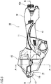
Fig. 1 is an external view of a binding machine in which a binder is set. -
Fig. 2 is an external view immediately after binding a bound member by the binding machine. -
Fig. 3A is a front view of the binder,Fig. 3B is a perspective view of the binder, andFig. 3C is a side view of a binder packet. -
Fig. 4A is an external view of the binder that binds the bound member, andFig. 4B is a front view of the binder that binds the bound member. -
Fig. 5 is a side view of the binding machine. -
Fig. 6 is a cross-sectional view of the binding machine taken along a line A-A inFig. 5 . -
Figs. 7A and 7B are cross-sectional views of the binding machine taken along a line B-B inFig. 5 , whereinFig. 7A is a view before a driver is operated, andFig. 7B is a view during operation of the driver. -
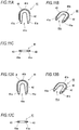
Figs. 8A and 8B are views of a binder according to a first modification, whereinFig. 8A is a front view of the binder, andFig. 8B is a perspective view of the binder. -
Figs. 9A and 9B are views of a binder according to a second modification, whereinFig. 9A is a front view of the binder, andFig. 9B is a perspective view of the binder. -
Figs. 10A, 10B and 10C are views of a binder according to a third modification, whereinFig. 10A is a front view of the binder,Fig. 10B is a perspective view of the binder, andFig. 10C is a bottom view of the binder. -
Figs. 11A, 11B and 11C are views of a binder according to a fourth modification, whereinFig. 11A is a front view of the binder,Fig. 11B is a perspective view of the binder, andFig. 11C is a bottom view of the binder. -
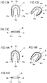
Figs. 12A, 12B and 12C are views of a binder according to a fifth modification, whereinFig. 12A is a front view of the binder,Fig. 12B is a perspective view of the binder, andFig. 12C is a bottom view of the binder. -
Figs. 13A, 13B and 13C are views of a binder according to a sixth modification, whereinFig. 13A is a front view of the binder,Fig. 13B is a perspective view of the binder, andFig. 13C is a bottom view of the binder. -
Figs. 14A, 14B and 14C are views of a binder according to a seventh modification, whereinFig. 14A is a front view of the binder,Fig. 14B is a perspective view of the binder, andFig. 14C is a bottom view of the binder. -
Figs. 15A, 15B and 15C are views of a binder according to an eighth modification, whereinFig. 15A is a front view of the binder,Fig. 15B is a perspective view of the binder, andFig. 15C is a bottom view of the binder. -
Figs. 16A, 16B and 16C are views of a binder according to a ninth modification, whereinFig. 16A is a front view of the binder,Fig. 16B is a perspective view of the binder, andFig. 16C is a bottom view of the binder. - Embodiments of the present invention are described with reference to the drawings.
- A
binder 41 according to the present embodiment is used by being loaded into a bindingmachine 10 as shown inFig. 1 , for example. The bindingmachine 10 binds a boundmember 50 by closing anopening 41c of thebinder 41. The bindingmachine 10 is used, for example, for binding a harness, a bag mouth, a field wire or an attraction string. In the present embodiment, a handheldtype binding machine 10 will be described as an example. However, thebinder 41 according to the present embodiment can be used not only for the handheldtype binding machine 10 but also for a stationary type binding machine. - As shown in
Fig. 1 , the bindingmachine 10 is covered with ahousing 11, and includes amotor accommodation portion 12, agrip portion 13 and anoutput portion 15. - The
motor accommodation portion 12 is provided at a rear portion of the bindingmachine 10, and a powersource connection portion 12a which connects an external power source is provided at a rear end portion thereof. By receiving a voltage supply from the powersource connection portion 12a, the bindingmachine 10 can perform various operations such as striking out thebinder 41. A cord which connects to an AC [0] power source may be connected to the powersource connection portion 12a, or a harness which connects to a rechargeable battery may be attached thereto. Although the bindingmachine 10 according to the present embodiment is of an electric type, the present invention is not limited thereto, and the bindingmachine 10 may be of a compressed air type. When the bindingmachine 10 is of the compressed air type, a connection portion which receives supply of compressed air may be provided instead of the powersource connection portion 12a. - Although not shown in the drawings, a motor and a control portion are housed in the
motor accommodation portion 12, so that driving of a driver 25 (described below) can be controlled. - The
grip portion 13 is a portion to be gripped by a user when the bindingmachine 10 is used. Thegrip portion 13 is provided in an intermediate portion of thehousing 11, and is formed in a constricted shape so as to be easily gripped by the user. Anoperation portion 14 is provided on an obliquely front side of thegrip portion 13 at a position that can be operated with an index finger when thegrip portion 13 is gripped. Theoperation portion 14 can be manually operated to perform a binding operation. Theoperation portion 13 is a swing member having a trigger shape in the present embodiment. The driver 25 (described below) is activated when theoperation portion 14 is pulled. - The
output portion 15 is provided in the vicinity of a tip end of the bindingmachine 10. At a tip end of theoutput portion 15, aprotrusion forming portion 17 protrudes in a substantially L-shape, and aninsertion opening 16 into which the boundmember 50 is inserted is opened inside theprotrusion forming portion 17. Thedriver 25 is housed in theoutput portion 15. Amagazine portion 35 is provided on a side portion of theoutput portion 15. - The
protrusion forming portion 17 is formed as a part of thehousing 11 or is integrally fixed to thehousing 11. Aclincher 18 is provided on an inner surface of theprotrusion forming portion 17 at a position where a tip end of the driver 25 (described below) is received. As shown inFig. 7A , theclincher 18 and thedriver 25 stand by at positions apart from each other before thebinder 41 is struck out, and theinsertion opening 16 is provided between theclincher 18 and thedriver 25. The bindingmachine 10 according to the present embodiment performs binding by striking out thebinder 41 toward theinsertion opening 16. - The
clincher 18 is configured to clinchleg portions 41 a of thebinder 41 struck out by thedriver 25 to complete the binding. Specifically, theclincher 18 is a plate against which thebinder 41 struck out by thedriver 25 is pressed. A groove for guiding theleg portions 41a of thebinder 41 is formed on a surface of theclincher 18, and theleg portions 41a of thebinder 41 pressed against theclincher 18 are bent inward (clinched) along the groove. - The
driver 25 is an elongated plate that performs a rectilinear motion by a drive mechanism (not shown) in order to strike out thebinder 41 toward theinsertion opening 16. As shown inFigs. 7A and 7B , thedriver 25 is slidably guided inside thehousing 11, and can reciprocate in a striking direction of thebinder 41. Thedriver 25 presses the struckbinder 41 against theclincher 18 to bend theleg portions 41a of thebinder 41, thereby closing theopening 41c to complete the binding. - The
magazine portion 35 is configured to load a plurality ofbinders 41. The bindingmachine 10 according to the present embodiment uses abinder packet 40 as shown inFig. 3C , and themagazine portion 35 can be loaded thereon such abinder packet 40. - The
binder packet 40 is configured by coupling a plurality ofbinders 41 to each other. As shown inFigs. 3A and 3B , eachbinder 41 includes a pair ofleg portions 41a and aconnection portion 41b connecting the pair ofleg portions 41a to be formed in a substantially U-shape. As shown inFig. 3C ,coupling portions 44 for couplingadjacent binders 41 are provided on front and back surfaces of theconnection portion 41b. Thecoupling portion 44 is formed to be weaker and thinner than the other portions so as to be easily broken. - The
opening 41c which holds the boundmember 50 is formed between the pair ofleg portions 41a. When thebinder 41 is struck out by thedriver 25 and clinched, theleg portions 41a are plastically deformed as shown inFigs. 4A and 4B such that the bound member can be held and bound. - As shown in
Fig. 6 , themagazine portion 35 includes arib 35a that enters between theleg portions 41a of the binder 41 (that is, theopening 41c). Agroove 35b that guides theconnection portion 41b of thebinder 41 is formed so as to face a tip end of therib 35a. - The
magazine portion 35 is provided with apusher 36 slidable along a longitudinal direction of themagazine portion 35. Thepusher 36 is configured to bias thebinder packet 40 loaded in themagazine portion 35 forward, and is always biased forward (in a direction of sending thebinder 41 to a standby portion 37 (described below)) by a spring (not shown). - The
magazine portion 35 is connected to the side portion of theoutput portion 15, and is configured to guide thebinder packet 40 inside theoutput portion 15. Inside theoutput portion 15 continuous with themagazine portion 35, thestandby portion 37 is provided which makes thebinder 41 stand by in a state for being struck out. Thestandby portion 37 is provided between thedriver 25 and theinsertion opening 16, and thebinder 41 standing by at thestandby portion 37 is struck out by thedriver 25 in a direction of theinsertion opening 16. - When the
binder packet 40 is loaded in themagazine portion 35, as shown inFig. 6 , thebinder packet 40 is loaded so as to straddle therib 35a, so that theconnection portion 41b of thebinder 41 passes through thegroove 35b of themagazine portion 35. When thebinder packet 40 is loaded in this manner, thebinder packet 40 is biased by thepusher 36 in a direction toward thestandby portion 37. - When binding is performed using the binding
machine 10 according to the present embodiment, the boundmember 50 is first inserted into theinsertion opening 16. When theoperation portion 14 is operated in this state, the motor rotates and thediver 25 strikes out thebinder 41 supplied to the standby portion 37 (seeFig. 7B ), and theleg portions 41a of the struckbinder 41 are clinched by theclincher 18 to complete the binding. - As shown in
Figs. 3A to 3C , thebinder 41 according to the present embodiment includes a substantiallyU-shaped base member 42 that is plastically deformable, and asurface member 43 provided on a surface of thebase member 42. - The
base member 42 is a main body of thebinder 41, and holds and binds the boundmember 50 by plastic deformation. As described above, thebase member 42 includes the pair ofleg portions 41a, theconnection portion 41b connecting the pair ofleg portions 41a, and thecoupling portions 44 which couplesadjacent connection portions 41b. - The
surface member 43 is a thin portion provided on a part of the surface of thebase member 42. For example, thesurface member 43 is formed integrally with thebase member 42 by two-layer molding. Thesurface member 43 is not necessarily formed integrally with thebase member 42. Thesurface member 43 may be adhered to thebase member 42, or thesurface member 43 may be provided by coating thebase member 42, or thesurface member 43 may be assembled to thebase member 42. - In the present embodiment, the
base member 42 is formed of plastic, and thesurface member 43 is formed of rubber. Therefore, a friction coefficient between thesurface member 43 and the boundmember 50 is larger than a friction coefficient between thebase member 42 and the boundmember 50. That is, thesurface member 43 provides the effect of slip prevention. In addition, thesurface member 43 has an elastic limit higher than that of thebase member 42, so that the impact can be alleviated when thesurface member 43 hits other members. - As shown in
Figs. 3A and 3B , since thesurface member 43 is provided on an inner side of the substantially U-shape of thebase member 42, thesurface member 43 comes into contact with the boundmember 50 during binding. - According to such a configuration, a large frictional force is generated between the
surface member 43 and the boundmember 50, so that the displacement of the boundmember 50 is reduced. Therefore, stable binding can be obtained. - As shown in
Figs. 3A to 3C , eachbinder 41 is coupled toother binders 41 on front and back surfaces thereof. The front and back surfaces (surfaces facing a coupling direction) of thebinder 41 are not provided with thesurface member 43. Thesurface member 43 is formed to be thinner than a thickness D (seeFig. 3C ) between the front and back surfaces of thebinder 41, and does not protrude from the front and back surfaces of thebinder 41. Therefore, when thebinder 41 is struck out by thedriver 25, thesurface member 43 does not contact a sliding guide surface inside thehousing 11, and the frictional resistance during striking is not increased. Accordingly, thebinder 41 can be struck out smoothly. Even when thesurface member 43 is provided, since the thickness of thebinder 41 is not affected, the pitch for connecting thebinders 41 is not required to be increased, so that the size of thebinder packet 40 can be kept small. - As shown in
Figs. 3A to 3C , tip ends of theleg portions 41a of thebinder 41 are not provided with thesurface member 43. Therefore, the problem should not occur that thesurface member 43 provided at tip ends of theleg portions 41a is peeled off due to friction when theleg portions 41a is clinched. In particular, as thesurface member 43 is not provided at outer tip ends of theleg portions 41a, peeling of thesurface member 43 during clinching can be prevented. - In the present embodiment, the
surface member 43 is provided in a substantially U-shape on an inner side of thebase member 42. However, the present invention is not limited thereto. - For example, as shown in
Figs. 8A and 8B ,surface members 43 may be respectively provided at positions facing each other on inner sides of the pair ofleg portions 41a. In other words, thesurface members 43 may be provided while avoiding an inner side of theconnection portion 41b. In such a configuration, a smooth striking of thebinder 41 can be realized while obtaining the effect of slip prevention by thesurface member 43. That is, when thebinder 41 is struck out, as shown inFig. 7B , a shearing force is applied to thecoupling portion 44 to break thecoupling portion 44 by pressing the remainingbinder packet 40 with therib 35a while striking a leadingbinder 41 with thedriver 25. At this time, when thesurface member 43 is provided on the inner side of theconnection portion 41b as shown inFigs. 3A to 3C , thesurface member 43 on the inner side of theconnection portion 41b contacts the tip end of therib 35a, so that the impact applied to thecoupling portion 44 is alleviated by thesurface member 43, and the instantaneous shearing force for breaking thecoupling portion 44 is decreased. If thecoupling portion 44 is harder to break due to a decrease in the instantaneous shear force, the striking speed may be slowed down, which causes poor binding, or thecoupling portion 44 may be stretched by being slowly broken, resulting in generation of burrs. In this respect, if thesurface member 43 is not provided on the inner side of theconnection portion 41b, buffering due to thesurface member 43 does not occur when thecoupling portion 44 is broken, so that theconnection portion 41b can be easily separated. In addition, since thesurface members 43 are provided on the inner side of theleg portions 41a that holds the boundmember 50, thesurface members 43 can sandwich the boundmember 50 from both directions. Therefore, the effect of preventing the boundmember 50 from slipping is sufficiently enhanced. - Further, when the
binder packet 40 is pushed by thepusher 36, if therib 35a and thesurface member 43 are in contact with each other in a wide range, the frictional resistance may be increased, which causes a sending failure. In this respect, if thesurface member 43 is not provided on the inner side of theconnection portion 41b serving as a contact portion with therib 35a, an increase in the frictional resistance can be prevented, and thebinder packet 40 can be reliably sent. - As shown in
Figs. 9A and 9B , thesurface member 43 may be provided on the inner side of theconnection portion 41b, and thesurface member 43 may not be provided at positions facing each other on the inner sides of the pair ofleg portions 41a. In such a configuration, since thesurface member 43 is provided on the inner side of theconnection portion 41b that hits the boundmember 50 when thebinder 41 is struck out, the boundmember 50 can be buffered and protected at a portion where the load is applied most. - As shown in
Figs. 10A to 14C , thesurface member 43 may be provided on an outer side of a substantially U-shape of thebase member 42. By providing thesurface member 43 on the outer side of thebase member 42, thesurface member 43 functions as a buffer when thebinder 41 hits other members, so that breakage can be reduced or prevented. - A shape of a surface of the
surface member 43 may have various forms, and may be determined according to the using environment and purpose. For example, as shown inFigs. 10A to 10C , the surface of thesurface member 43 may be formed flat. As shown inFigs. 11A to 11C , thesurface member 43 may be formed in a rib shape. As shown inFigs. 12A to 12C , thesurface member 43 may be formed in a mountain shape in cross section. As shown inFigs. 13A to 13C , thesurface member 43 may be formed in a concave shape in cross section. As shown inFigs. 14A to 14C , thesurface member 43 may be formed to bulge in an R-shape in cross section. - As shown in
Figs. 15A to 15C , thesurface member 43 may be provided on both inner and outer sides of thebase member 42. - As shown in
Figs. 16A to 16C , thesurface member 43 may be provided so as to coat thebase member 42. - As described above, the
binder 41 according to the present embodiment includes an elasticallydeformable surface member 43 on the surface of the substantiallyU-shaped base member 42 that is plastically deformable. According to such a configuration, as providing thesurface member 43 on the inner surface and/or the outer surface of thebase member 42, the effects such as stable binding and/or prevention of breakage can be obtained. - That is, if the
surface member 43 is provided on the inner surface of thebase member 42, the frictional resistance at a position in contact with the boundmember 50 can be improved and the holding force of thebinder 41 can be increased. Therefore, binding can be stably performed without displacement of thebinder 41 even if the binding strength is appropriate not as strong as causing damage to the boundmember 50. Further, the effect of preventing damage when thebinder 41 hits other members can also be expected. - If the
surface member 43 is provided on the outer surface of thebase member 42, the buffering property at a position hitting other members can be improved. Therefore, even when thebinder 41 is used at a location where vibration occurs, damage to other members can be reduced and breakage of thebinder 41 can be prevented. Since the impact at hitting to other members is alleviated, the effect of preventing thebinder 41 from falling off by the impact can be expected. - In the above-described embodiment, the
surface member 43 is provided on both the pair ofleg portions 41a. However, the present invention is not limited thereto, and thesurface member 43 may be provided only on one of theleg portions 41a. - This application is based on Japanese Patent Application filed on April 27, 2017 (Japanese Patent Application No.
2017-088485 -
- 10 binding machine
- 50 housing
- 12 motor accommodation portion
- 12a power source connection portion
- 13 grip portion
- 14 operation portion
- 15 output portion
- 16 insertion opening
- 17 protrusion forming portion
- 18 clincher
- 25 driver
- 35 magazine portion
- 35a rib
- 35b groove
- 36 pusher
- 37 standby portion
- 40 binder packet
- 41 binder
- 41a leg portion
- 41b connection portion
- 41c opening
- 42 base member
- 43 surface member
- 44 coupling portion
- 50 bound member
Claims (10)
- A binder configured to bind a bound member by being struck out from a binding machine, the binder comprising:a substantially U-shaped base member that is plastically deformable; anda surface member that is provided on a surface of the base member.
- The binder according to claim 1,
wherein a friction coefficient between the surface member and the bound member is larger than a friction coefficient between the base member and the bound member. - The binder according to claim 1 or 2,
wherein the surface member has an elastic limit higher than that of the base member. - The binder according to any one of claims 1 to 3,
wherein the surface member is provided on a substantially U-shaped inner surface of the base member. - The binder according to claim 4,
wherein the surface member is provided in a substantially U-shape on the inner surface of the base member. - The binder according to claim 4,
wherein the base member includes a pair of leg portions and a connection portion connecting the pair of leg portions, and
wherein the surface member is provided at positions facing each other on inner surfaces of the pair of leg portions. - The binder according to claim 4,
wherein the base member includes a pair of leg portions and a connection portion connecting the pair of leg portions, and
wherein the surface member is provided on an inner surface of the connection portion, and the surface member is not provided at positions facing each other on inner surfaces of the pair of leg portions. - The binder according to any one of claims 1 to 7,
wherein the surface member is provided on a substantially U-shaped outer surface of the base member. - The binder according to any one of claims 1 to 8,
wherein the base member is formed of plastic, and the surface member is formed of rubber. - A binder packet comprising:a plurality of binders coupled to each other, each being the binder according to any one of claims 1 to 9,wherein each of the binders is coupled to other of the binders on front and back surfaces thereof, andwherein the front and back surfaces of each of the binders are not provided with the surface member.
Applications Claiming Priority (2)
| Application Number | Priority Date | Filing Date | Title |
|---|---|---|---|
| JP2017088485A JP2018184201A (en) | 2017-04-27 | 2017-04-27 | Binding tool and linking tool |
| PCT/JP2018/016889 WO2018199199A1 (en) | 2017-04-27 | 2018-04-25 | Binder, and binder packet |
Publications (2)
| Publication Number | Publication Date |
|---|---|
| EP3617078A1 true EP3617078A1 (en) | 2020-03-04 |
| EP3617078A4 EP3617078A4 (en) | 2020-12-30 |
Family
ID=63919330
Family Applications (1)
| Application Number | Title | Priority Date | Filing Date |
|---|---|---|---|
| EP18790451.1A Withdrawn EP3617078A4 (en) | 2017-04-27 | 2018-04-25 | Binder, and binder packet |
Country Status (7)
| Country | Link |
|---|---|
| US (1) | US20200031508A1 (en) |
| EP (1) | EP3617078A4 (en) |
| JP (1) | JP2018184201A (en) |
| KR (1) | KR20200003784A (en) |
| CN (1) | CN110446658A (en) |
| TW (1) | TWI709512B (en) |
| WO (1) | WO2018199199A1 (en) |
Families Citing this family (3)
| Publication number | Priority date | Publication date | Assignee | Title |
|---|---|---|---|---|
| JP7040088B2 (en) * | 2018-02-09 | 2022-03-23 | マックス株式会社 | Tie |
| JP2020023337A (en) * | 2018-08-07 | 2020-02-13 | マックス株式会社 | Binding machine |
| CN113531262A (en) * | 2021-07-27 | 2021-10-22 | 圣拓热控科技江苏有限公司 | A device and method for bundling an electric heating cable and a pipeline |
Family Cites Families (13)
| Publication number | Priority date | Publication date | Assignee | Title |
|---|---|---|---|---|
| US3015824A (en) * | 1959-08-18 | 1962-01-09 | Grace W R & Co | Clip crimping apparatus |
| US3237256A (en) * | 1962-06-04 | 1966-03-01 | Signode Corp | Seal for ligature joint |
| JPS5531502A (en) * | 1978-08-14 | 1980-03-05 | Max Co Ltd | Tense wire applying device |
| US6308745B1 (en) * | 2000-06-21 | 2001-10-30 | Illinois Tool Works Inc. | Manually-operated sealing tool for joining end portions of plastic strapping, seal member, and sealed joint formed thereby |
| JP4848594B2 (en) * | 2001-05-09 | 2011-12-28 | マックス株式会社 | Clip connector |
| JP2002362590A (en) * | 2001-05-31 | 2002-12-18 | Max Co Ltd | Clip and clip clincher |
| JP3840401B2 (en) * | 2001-06-01 | 2006-11-01 | 株式会社古川製作所 | Bag mouth bundling method and bundling apparatus |
| JP4736296B2 (en) * | 2001-06-15 | 2011-07-27 | マックス株式会社 | Bundling device |
| JP2003056519A (en) * | 2001-08-10 | 2003-02-26 | Toppan Printing Co Ltd | Binding device and its assembly |
| JP2004010125A (en) * | 2002-06-07 | 2004-01-15 | Max Co Ltd | Bundling clip |
| JP4168947B2 (en) * | 2004-02-13 | 2008-10-22 | マックス株式会社 | Binder coupling body and bundling device |
| JP2009287585A (en) * | 2008-05-27 | 2009-12-10 | Konishi Co Ltd | Fastener assembly and its method for manufacturing |
| JP7064282B2 (en) | 2015-11-11 | 2022-05-10 | 株式会社オハラ | Optical glass, preforms and optical elements |
-
2017
- 2017-04-27 JP JP2017088485A patent/JP2018184201A/en active Pending
-
2018
- 2018-04-25 WO PCT/JP2018/016889 patent/WO2018199199A1/en not_active Ceased
- 2018-04-25 KR KR1020197027744A patent/KR20200003784A/en not_active Ceased
- 2018-04-25 EP EP18790451.1A patent/EP3617078A4/en not_active Withdrawn
- 2018-04-25 CN CN201880019883.7A patent/CN110446658A/en active Pending
- 2018-04-25 US US16/496,673 patent/US20200031508A1/en not_active Abandoned
- 2018-04-26 TW TW107114227A patent/TWI709512B/en not_active IP Right Cessation
Also Published As
| Publication number | Publication date |
|---|---|
| KR20200003784A (en) | 2020-01-10 |
| CN110446658A (en) | 2019-11-12 |
| TW201841800A (en) | 2018-12-01 |
| JP2018184201A (en) | 2018-11-22 |
| TWI709512B (en) | 2020-11-11 |
| WO2018199199A1 (en) | 2018-11-01 |
| EP3617078A4 (en) | 2020-12-30 |
| US20200031508A1 (en) | 2020-01-30 |
Similar Documents
| Publication | Publication Date | Title |
|---|---|---|
| US20200031508A1 (en) | Binder, and binder packet | |
| US20110108300A1 (en) | Hook for electric power tool and rechargeable electric power tool equipped with the hook | |
| EP3444074B1 (en) | Driving tool | |
| US20080156844A1 (en) | Staple gun | |
| US11524396B2 (en) | Fastener tool | |
| EP3617079A1 (en) | Binder | |
| US20120118933A1 (en) | Nail gun with multi-gauge structure | |
| US8281971B2 (en) | Labor-saving stapler | |
| JP3165751U (en) | Snap fastener attaching machine | |
| JP5772506B2 (en) | Contact arm deformation prevention mechanism | |
| US10576614B2 (en) | Stapler | |
| US11065751B2 (en) | Labor-saving stapler | |
| CN204505177U (en) | Improved structure of nail gun transmission | |
| CN110461715A (en) | strapping machine | |
| CN210081636U (en) | Optimized mechanism for preventing bending of staple on stapler | |
| US7156477B1 (en) | Release-control stop member of a sliding rail assembly for drawer | |
| CN115675986A (en) | strapping machine | |
| EP1868776B1 (en) | Hammer tacker | |
| WO2018199198A1 (en) | Binder | |
| TWI257891B (en) | Nail driving device for a nail gun | |
| CN223301637U (en) | Driving actuator for electric snap ring nail gun and electric snap ring nail gun | |
| JP2000351042A (en) | Riveting tools | |
| JP2018184213A (en) | Binding machine | |
| KR101452597B1 (en) | Electrically powered rivet gun apparatus | |
| JP3780797B2 (en) | Nail driving machine and nail feeder |
Legal Events
| Date | Code | Title | Description |
|---|---|---|---|
| STAA | Information on the status of an ep patent application or granted ep patent |
Free format text: STATUS: THE INTERNATIONAL PUBLICATION HAS BEEN MADE |
|
| PUAI | Public reference made under article 153(3) epc to a published international application that has entered the european phase |
Free format text: ORIGINAL CODE: 0009012 |
|
| STAA | Information on the status of an ep patent application or granted ep patent |
Free format text: STATUS: REQUEST FOR EXAMINATION WAS MADE |
|
| 17P | Request for examination filed |
Effective date: 20190920 |
|
| AK | Designated contracting states |
Kind code of ref document: A1 Designated state(s): AL AT BE BG CH CY CZ DE DK EE ES FI FR GB GR HR HU IE IS IT LI LT LU LV MC MK MT NL NO PL PT RO RS SE SI SK SM TR |
|
| AX | Request for extension of the european patent |
Extension state: BA ME |
|
| DAV | Request for validation of the european patent (deleted) | ||
| DAX | Request for extension of the european patent (deleted) | ||
| A4 | Supplementary search report drawn up and despatched |
Effective date: 20201127 |
|
| RIC1 | Information provided on ipc code assigned before grant |
Ipc: B65B 13/34 20060101AFI20201124BHEP Ipc: B65B 51/04 20060101ALI20201124BHEP Ipc: B65B 67/02 20060101ALI20201124BHEP |
|
| GRAP | Despatch of communication of intention to grant a patent |
Free format text: ORIGINAL CODE: EPIDOSNIGR1 |
|
| STAA | Information on the status of an ep patent application or granted ep patent |
Free format text: STATUS: GRANT OF PATENT IS INTENDED |
|
| INTG | Intention to grant announced |
Effective date: 20210831 |
|
| STAA | Information on the status of an ep patent application or granted ep patent |
Free format text: STATUS: THE APPLICATION IS DEEMED TO BE WITHDRAWN |
|
| 18D | Application deemed to be withdrawn |
Effective date: 20220111 |