EP3617010B1 - Lokalisierung drahtloser knoten - Google Patents
Lokalisierung drahtloser knoten Download PDFInfo
- Publication number
- EP3617010B1 EP3617010B1 EP19192312.7A EP19192312A EP3617010B1 EP 3617010 B1 EP3617010 B1 EP 3617010B1 EP 19192312 A EP19192312 A EP 19192312A EP 3617010 B1 EP3617010 B1 EP 3617010B1
- Authority
- EP
- European Patent Office
- Prior art keywords
- wideband
- sensing units
- wideband spectrum
- transceiver
- transmission
- Prior art date
- Legal status (The legal status is an assumption and is not a legal conclusion. Google has not performed a legal analysis and makes no representation as to the accuracy of the status listed.)
- Active
Links
Images



Classifications
-
- H—ELECTRICITY
- H04—ELECTRIC COMMUNICATION TECHNIQUE
- H04W—WIRELESS COMMUNICATION NETWORKS
- H04W64/00—Locating users or terminals or network equipment for network management purposes, e.g. mobility management
- H04W64/006—Locating users or terminals or network equipment for network management purposes, e.g. mobility management with additional information processing, e.g. for direction or speed determination
-
- G—PHYSICS
- G01—MEASURING; TESTING
- G01S—RADIO DIRECTION-FINDING; RADIO NAVIGATION; DETERMINING DISTANCE OR VELOCITY BY USE OF RADIO WAVES; LOCATING OR PRESENCE-DETECTING BY USE OF THE REFLECTION OR RERADIATION OF RADIO WAVES; ANALOGOUS ARRANGEMENTS USING OTHER WAVES
- G01S13/00—Systems using the reflection or reradiation of radio waves, e.g. radar systems; Analogous systems using reflection or reradiation of waves whose nature or wavelength is irrelevant or unspecified
- G01S13/74—Systems using reradiation of radio waves, e.g. secondary radar systems; Analogous systems
- G01S13/76—Systems using reradiation of radio waves, e.g. secondary radar systems; Analogous systems wherein pulse-type signals are transmitted
- G01S13/767—Responders; Transponders
-
- G—PHYSICS
- G01—MEASURING; TESTING
- G01S—RADIO DIRECTION-FINDING; RADIO NAVIGATION; DETERMINING DISTANCE OR VELOCITY BY USE OF RADIO WAVES; LOCATING OR PRESENCE-DETECTING BY USE OF THE REFLECTION OR RERADIATION OF RADIO WAVES; ANALOGOUS ARRANGEMENTS USING OTHER WAVES
- G01S13/00—Systems using the reflection or reradiation of radio waves, e.g. radar systems; Analogous systems using reflection or reradiation of waves whose nature or wavelength is irrelevant or unspecified
- G01S13/87—Combinations of radar systems, e.g. primary radar and secondary radar
- G01S13/878—Combination of several spaced transmitters or receivers of known location for determining the position of a transponder or a reflector
-
- G—PHYSICS
- G01—MEASURING; TESTING
- G01S—RADIO DIRECTION-FINDING; RADIO NAVIGATION; DETERMINING DISTANCE OR VELOCITY BY USE OF RADIO WAVES; LOCATING OR PRESENCE-DETECTING BY USE OF THE REFLECTION OR RERADIATION OF RADIO WAVES; ANALOGOUS ARRANGEMENTS USING OTHER WAVES
- G01S5/00—Position-fixing by co-ordinating two or more direction or position line determinations; Position-fixing by co-ordinating two or more distance determinations
- G01S5/02—Position-fixing by co-ordinating two or more direction or position line determinations; Position-fixing by co-ordinating two or more distance determinations using radio waves
- G01S5/0205—Details
- G01S5/0218—Multipath in signal reception
-
- G—PHYSICS
- G01—MEASURING; TESTING
- G01S—RADIO DIRECTION-FINDING; RADIO NAVIGATION; DETERMINING DISTANCE OR VELOCITY BY USE OF RADIO WAVES; LOCATING OR PRESENCE-DETECTING BY USE OF THE REFLECTION OR RERADIATION OF RADIO WAVES; ANALOGOUS ARRANGEMENTS USING OTHER WAVES
- G01S5/00—Position-fixing by co-ordinating two or more direction or position line determinations; Position-fixing by co-ordinating two or more distance determinations
- G01S5/02—Position-fixing by co-ordinating two or more direction or position line determinations; Position-fixing by co-ordinating two or more distance determinations using radio waves
- G01S5/06—Position of source determined by co-ordinating a plurality of position lines defined by path-difference measurements
-
- G—PHYSICS
- G01—MEASURING; TESTING
- G01S—RADIO DIRECTION-FINDING; RADIO NAVIGATION; DETERMINING DISTANCE OR VELOCITY BY USE OF RADIO WAVES; LOCATING OR PRESENCE-DETECTING BY USE OF THE REFLECTION OR RERADIATION OF RADIO WAVES; ANALOGOUS ARRANGEMENTS USING OTHER WAVES
- G01S5/00—Position-fixing by co-ordinating two or more direction or position line determinations; Position-fixing by co-ordinating two or more distance determinations
- G01S5/02—Position-fixing by co-ordinating two or more direction or position line determinations; Position-fixing by co-ordinating two or more distance determinations using radio waves
- G01S5/10—Position of receiver fixed by co-ordinating a plurality of position lines defined by path-difference measurements, e.g. omega or decca systems
-
- H—ELECTRICITY
- H04—ELECTRIC COMMUNICATION TECHNIQUE
- H04B—TRANSMISSION
- H04B17/00—Monitoring; Testing
- H04B17/30—Monitoring; Testing of propagation channels
- H04B17/382—Monitoring; Testing of propagation channels for resource allocation, admission control or handover
-
- G—PHYSICS
- G01—MEASURING; TESTING
- G01S—RADIO DIRECTION-FINDING; RADIO NAVIGATION; DETERMINING DISTANCE OR VELOCITY BY USE OF RADIO WAVES; LOCATING OR PRESENCE-DETECTING BY USE OF THE REFLECTION OR RERADIATION OF RADIO WAVES; ANALOGOUS ARRANGEMENTS USING OTHER WAVES
- G01S13/00—Systems using the reflection or reradiation of radio waves, e.g. radar systems; Analogous systems using reflection or reradiation of waves whose nature or wavelength is irrelevant or unspecified
- G01S13/02—Systems using reflection of radio waves, e.g. primary radar systems; Analogous systems
- G01S13/0209—Systems with very large relative bandwidth, i.e. larger than 10 %, e.g. baseband, pulse, carrier-free, ultrawideband
-
- G—PHYSICS
- G01—MEASURING; TESTING
- G01S—RADIO DIRECTION-FINDING; RADIO NAVIGATION; DETERMINING DISTANCE OR VELOCITY BY USE OF RADIO WAVES; LOCATING OR PRESENCE-DETECTING BY USE OF THE REFLECTION OR RERADIATION OF RADIO WAVES; ANALOGOUS ARRANGEMENTS USING OTHER WAVES
- G01S5/00—Position-fixing by co-ordinating two or more direction or position line determinations; Position-fixing by co-ordinating two or more distance determinations
- G01S5/02—Position-fixing by co-ordinating two or more direction or position line determinations; Position-fixing by co-ordinating two or more distance determinations using radio waves
- G01S5/0273—Position-fixing by co-ordinating two or more direction or position line determinations; Position-fixing by co-ordinating two or more distance determinations using radio waves using multipath or indirect path propagation signals in position determination
Definitions
- This disclosure relates generally to localization of wireless nodes, and more specifically to localization of wireless nodes with wideband spectrum sensing and correlation to historical channel data.
- US20150282112 discloses a method of estimating a position of an object comprising, receiving a plurality of signals transmitted between each of a respective plurality of reference stations of a known position and the object. The method further comprises, for each received signal: processing the signal using a matrix featuring a characteristic power delay profile and a characteristic signal waveform to provide a processed signal, and calculating a direct estimate of the position of the object based, at least in part, on the processed signals.
- EP2042885 discloses a system, method and transceiver for both wireless communication and distance estimation between a plurality of devices in a wireless network. The system comprises system operative nodes (SON) and one central monitoring node (CMN) configured for calculating through triangulation the estimated absolute position of the SON.
- SON system operative nodes
- CMS central monitoring node
- the distance to each associated SON is estimated via a ranging process performed by calculating the propagation delay between both nodes and storing the estimated distance in an associated dynamic node table (ADNT), each node of the system being equipped with a transceiver.
- US20080167051 discloses a method of determining the location of a target. The method includes initializing a set of base stations to determine their location relative to each other.
- US20140057655 discloses a ranging method by using a first signal transmitted by a first device, and a second signal generated and transmitted by a target device in response to the first signal.
- nLOS Line of Sight
- a system for localizing a wireless node comprising:
- the ADC may include a Radio Frequency Front End amplifier having a fixed gain.
- the ADC may include an over-sampling circuit for sampling the transmission, wherein the ADC bandwidth is greater than, or equal to, ten times the receive bandwidth.
- the system may further comprise a signal pre-processing circuit configured to limit an output of the ADC to the acquisition window and the frequency range corresponding to the channel number, to form the plurality of wideband samples.
- each of the respective wideband samples may be further limited by a frequency range corresponding to a channel number.
- the master transceiver and the slave transceiver each may transceive with a Wireless Personal Area Network protocol.
- the physical infrastructure may be an automobile and the slave transceiver is a key Frequency Operated Button.
- a method for localizing a wireless node comprising:
- the method may further comprise exiting a low power state of the wideband spectrum-sensing units in response to the master transceiver receiving the transmission and communicating an activity status from the master transceiver to each of the wideband spectrum-sensing units.
- each power delay profile may include a plurality of signals having a respective magnitude and multipath time delay, each signal corresponding to a respective path between the slave transceiver and the respective wideband spectrum-sensing unit.
- the method may further comprise determining a direct path between the slave transceiver and the respective wideband spectrum-sensing unit from the respective path with the shortest multipath time delay.
- Embodiments of systems and methods described herein provide for determining an accurate location of a wireless node relative to an infrastructure.
- the location is determined with at least two wideband spectrum-sensing units that are synchronized in time and have defined locations on the infrastructure.
- the wideband spectrum-sensing units perform wideband measurements of a transmission from the wireless node through a channel to a wireless receiver, in an unobtrusive manner.
- the plurality of wideband measurements are further correlated with previously determined channel information and combined with a Time Difference Of Arrival (TDOA) method to determine the location of the wireless node.
- TDOA Time Difference Of Arrival
- the localization method enables environmental mapping as well as the detection of potential spoofing attempts to access the wireless receiver.
- a wireless node includes a key Frequency Operated Button (FOB) and the infrastructure is an automobile.
- FOB Frequency Operated Button
- the key FOB can unlock specific doors on the automobile, or perform other location specific tasks.
- a phone location can be determined relative to the automobile. Determination of direct and indirect paths between the wireless transmitter and the wireless receiver enables mapping of the channel environment including the infrastructure, transmitter, receiver, and intervening objects, which contribute to multipath.
- specific features of the channel environment are compared to previous determinations, or prerecorded scenarios, of the environment to detect the presence of an occupant in the automobile or an open door, for example.
- the signal characteristics e.g., strength and location
- the detected key FOB are used to detect spoofing attempts at gaining access to the wireless receiver with an intervening device.
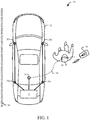
- FIG. 1 shows a system 10 for localizing a wireless node, in accordance with claim 1 .
- the system 10 includes an automobile 12, which is a physical infrastructure having a variety of electronically controllable functions, controlled by a master transceiver 14.
- a master transceiver 14 controls the locking or unlocking or doors on the automobile 12.
- the master transceiver 14 opens or closes windows on the automobile 12, or controls an entertainment center (e.g., a radio).
- an entertainment center e.g., a radio
- the master transceiver 14 communicates with (e.g., transceives), with a slave transceiver 16 using a wireless communication protocol for transmitting and receiving data.
- the slave transceiver 16 is a key FOB operating with the BLE protocol.
- the master transceiver 14 and the slave transceiver 16 transceive with a Personal Area Network (PAN) protocol, examples of which include but are not limited to the communication protocols based on the family of IEEE 802.15 standards, such as Bluetooth ® , WiFi ® , ANT ® , Zigbee ® , and low powered versions of communication protocols, such as BLE, and the like.
- PAN Personal Area Network
- System 10 includes four wideband spectrum-sensing units 20a, 20b, 20c and 20d, (generally 20), mounted on the automobile 12 with sufficient separation to minimize blocking of each of the transmission channels between each of the wideband spectrum-sensing units 20 and the slave transceiver 16 due to an intervening object.
- Various embodiments according to claim 1 include different placements and quantities of the wideband spectrum-sensing units 20.
- Each of the wideband spectrum-sensing units 20 and the master transceiver 14 are connected to a processor 22.
- the connection between the processor 22 to each of the wideband spectrum-sensing units 20 and the master transceiver 14 is made over a high speed data bus, such as an automotive Ethernet bus, although other bus protocols are envisioned within the scope of this disclosure.
- the processor 22 is a Digital Signal Processor capable of performing convolutions and correlations between data sets.
- the processor 22 includes a system interface (not shown).
- the system interface includes, but is not limited to, a bidirectional data port for transferring data to or from the processor 22, or a display and keypad interface.
- the slave transceiver 16 communicates with the master transceiver 14 through a channel 24.
- the channel 24 between the slave transceiver and the master transceiver 14 is blocked, for example by the presence of an intervening object such as a human 26.
- the channel 24 includes a multitude of transmission paths (e.g., "multipath"), as a result of reflections from electrically reflective surfaces, such as a reflective wall 28.
- the physical infrastructure is a building (e.g., a home or a shopping mall), with walls, furnishing and the like, each of which can contribute to the formation of multipath channels or blocking of the transmission.
- the wideband spectrum-sensing units 20 Independent of the communication between the slave transceiver 16 and the master transceiver 14, the wideband spectrum-sensing units 20 also receive the transmission from the slave transceiver 16, sampled with a higher bandwidth than the bandwidth of the master transceiver 14. The transmission samples from the wideband spectrum-sensing units 20 are compared with previously determined channel data to form respective power delay profiles, and then TDOA methods are used to determine the slave location of the slave transceiver 16.
- WPAN Wireless PAN
- the sensing locations are stored in a first memory prior to executing the TDOA method.
- the first memory (not shown) is connected to the processor 22.
- the master transceiver 14 also informs each of the wideband spectrum-sensing units 20 as to the channel (e.g., for WPAN protocol), and the start and end time of the transmission received from the slave transceiver 16.
- a WPAN channel is defined by one of a plurality of sequential frequency ranges.
- the master transceiver 14 only provides the start and end time to each of the wideband spectrum-sensing units 20, thereby simplifying the design of the master transceiver 14 and each of the wideband spectrum-sensing units 20 at the expense of processing, with the processor 22, additionally sampled data from more than one channel.
- Each of the wideband spectrum-sensing units 20 and the master transceiver 14 are also temporally synchronized to a time reference, (not shown).
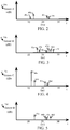
- FIG. 2 shows a plurality of received transmissions 40a, 40b, 40c and 40d, (generally 40), transmitted by the slave transceiver 16 and received by the wideband spectrum-sensing unit 20a.
- the different magnitudes and multipath time delays for each of the received transmissions 40 result from a combination of direct and indirect paths taken by each received transmission 40.
- FIG. 3 shows a plurality of received transmissions 42a, 42b, 42c, 42d, 42e and 42f, (generally 42), transmitted by the slave transceiver 16 and received by the wideband spectrum-sensing unit 20b.
- the different magnitudes and multipath time delays for each of the received transmissions 40 result from a combination of direct and indirect paths taken by each received transmission 40.
- FIG. 4 shows a plurality of received transmissions 44a, 44b, 44c, and 44d, (generally 44), transmitted by the slave transceiver 16 and received by the wideband spectrum-sensing unit 20c.
- the different magnitudes and multipath time delays for each of the received transmissions 40 result from a combination of direct and indirect paths taken by each received transmission 40.
- FIG. 5 shows a plurality of received transmissions 46a, 46b, 46c and 46f, (generally 46), transmitted by the slave transceiver 16 and received by the wideband spectrum-sensing unit 20d.
- the different magnitudes and multipath time delays for each of the received transmissions 40 result from a combination of direct and indirect paths taken by each received transmission 40.
- FIG. 6 shows a flowchart representation of a method for generating a power delay profile 58 for one of the wideband spectrum-sensing units 20 shown in FIG. 1 .
- a plurality of samples 50 (corresponding to one of the group of samples 40, 42, 44 or 46 from FIG. 2 to FIG. 5 ), are stored in a second (buffer) memory by the respective wideband spectrum-sensing unit 20.
- the samples 50 are time limited by the wideband spectrum-sensing unit 20 with a start time 54 and a stop time 56 to reduce the second memory storage requirements and subsequent computation burden by the processor 22.
- the start time 54 and stop time 56 correspond to the start and ending of a transmission from the slave transceiver 16 to the master transceiver 14, wherein the start time 54 and stop time 56 are subsequently transmitted to each of the wideband spectrum-sensing units 20 by the master transceiver 14.
- the start time 54 and stop time 56 include additional time guard bands to ensure that the transmission is fully captured and sampled by each of the wideband spectrum-sensing units 20.
- the samples 50 are retrieved from the second memory by the processor 22 and correlated to a plurality of reconstructed samples 52 to determine each of the transmissions 60a, 60b, 60c, 60d, 60e, 60f, 60g, 60h, 60i and 60j, (generally 60), thereby forming the power delay profile 58.
- Each transmission 60 corresponds to a unique path, (either a direct or multipath), between the slave transceiver 16 and the respective wideband spectrum-sensing unit 20.
- the reconstructed samples 52 are based on previous transmissions received by the wideband spectrum-sensing units 20, and retrieved from a first memory by the processor 22.
- the first memory is connected to, or forms part of, the processor 22.
- the reconstructed samples 52 have an adjusted time resolution to match the samples 50.
- the reconstructed samples 52 are formed prior to the completion of generating the samples 50 (e.g., prior to the stop time 56).
- the correlation of the samples 50 with the reconstructed samples 52 is performed with a convolution method.
- the convolution method is replaced with a Maximum Likelihood method, a Matrix Pencil method or a Set-Theoretic Deconvolution method, to reduce the computational burden on the processor 22 for computing a direct path between the slave transceiver 16 and at least one of the wideband spectrum-sensing units 20a.
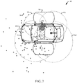
- FIG. 7 shows a TDOA method 80 in accordance with claim 1 based on trilateration-based particle filtering for determining the slave location of the slave transceiver 16 relative to the automobile 12, from the respective first paths 60a of each of the plurality of power delay profiles 58.
- Other TDOA methods are considered to be within the scope of this disclosure and are not limited by the particle filtering approach.
- the method 80 includes a plurality of distance measurement rings 82a, 82b, 82c and 82d, (generally 82), corresponding to respective wideband spectrum-sensing units 20a, 20b, 20c and 20d.
- the automobile 12 include door zones 90 and 92.
- the various "+" markers 94 show an initial particle distribution, and the "o" markers 96 show converged particles. In the embodiment shown in FIG. 7 , the converged particles 96, show that the slave transceiver 16 is proximate to the door zone 90.
- FIG. 8 shows a system 100 for localizing a wireless node, in accordance with claim 1 .
- a slave transceiver 102 transmits a transmission with an antenna 104.
- a master transceiver 106 receives the transmission with an antenna 108.
- a plurality of wideband spectrum-sensing units 110a and 110b, (generally 110) also receive the transmission with respective antennas 112a and 112b, (generally 112).
- the master transceiver 106 and each of the wideband spectrum-sensing units 110 have bidirectional communication with a processor 120.
- the system includes a processor 120 a system interface 122 and a memory 124.
- the system interface 122 includes a bidirectional port for programming and receiving data from the processor 120. In another embodiment, according to claim 1, the system interface 122 includes a display and keypad for modifying programs or settings of the processor 120. In one embodiment, according to claim 1, the memory 124 is volatile or non-volatile RAM. In another embodiment, according to claim 1, the memory 124 is integrated with the processor 120 having a single semiconductor. In one embodiment, according to claim 1, the processor 120 is a Digital Signal Processor, however other processor architectures capable of performing convolutions are envisioned within the scope of this disclosure.
- each of the wideband spectrum-sensing units 110 includes a Filter and Mixer 140 receiving the transmission from the antenna 112.
- the Filter and Mixer 140 limits the bandwidth of the transmission to the Industrial, Scientific and Medical Radio (ISM) band and down coverts the received transmission.
- the output of the Filter and Mixer 140 is sampled by a wideband Analog to Digital Converter (ADC) 142 to provide a plurality of wideband samples.
- ADC Analog to Digital Converter
- the ADC 142 directly samples the transmission received at the antenna 112 to reduce the number of components of each of the wideband spectrum-sensing units 110 at the expense of requiring a more complex ADC 142.
- the wideband ADC 142 oversamples the ISM band to reduce filtering requirements.
- the wideband ADC 142 includes a fixed gain Radio Front End (RFE) receiver to reduce delay variation.
- the ADC 142 does not include an RFE receiver for simplifying the ADC 142 design at the expense of system accuracy.
- the wideband ADC 142 is a 14 bit Sigma-Delta converter sampling with at least 1 Giga-Samples/second.
- the output samples of the wideband ADC 142 are received by pre-processing circuits 144.
- the pre-processing circuits 144 limit the samples received from the wideband ADC 142 by a channel number and acquisition window, prior to storing the limited sample data in a buffer memory 145 (e.g., a second memory).
- a buffer memory 145 e.g., a second memory.
- the buffer memory 145 is included with the pre-processing circuits 144.
- the limited sample data are transferred to the processor 120 for storage in the first memory 124.
- Each of the wideband spectrum-sensing unit 110 includes a reference clock 146 configured to be synchronized to each of the wideband spectrum-sensing units 110 and the master transceiver 106 with wired or wireless connections.
- the control settings circuit 148 receives the channel number and acquisition window received from the master transceiver 106.
- the control settings circuit 148 receives the channel number, the channel start time and the channel stop time.
- the channel number is defined by a frequency range of 2 MHz, being one of a series of consecutive channels defined by the WPAN protocol.
- the acquisition window is defined by the channel start and channel stop time as received by the master transceiver 106.
- the control settings circuit 148 also receives the expected signal type (e.g., a BLE packet or continuous tone extension (CTE)), from the master transceiver 106 for use in determining the angle of arrival of the transmission from the slave transceiver 102.
- the control settings circuit 148 causes one or more of the circuits of the wideband spectrum-sensing unit 110 to exit a low power state upon detecting the channel start by the master transceiver 106, and returning to the low power state after the channel stop.
- FIG. 10 shows a method for localization of a wireless node, in accordance with an embodiment of the present disclosure.
- the master transceiver 106 is synchronized to the time reference (e.g., reference clock) 146.
- each of the wideband spectrum-sensing units 110 is synchronized to the time reference 146.
- the wideband spectrum-sensing units 110 are synchronized to each other to perform the TDOA method, while the master transceiver 106 is synchronized to provide the acquisition window for limiting sample data.
- the physical location of each of the wideband spectrum-sensing units 110 is stored in a first memory 124. In various embodiments according to claim 1, 162, 164 and 166 are performed in parallel or in any sequential combination.
- the slave transceiver 102 transmits a transmission, and at 172 and 174, the master transceiver 106 and each of the wideband spectrum-sensing units 110 respectively receive the transmission.
- the master transceiver 106 decodes the transmission to determine the channel number, channel start time and channel stop time (e.g., to define the acquisition window). In one embodiment at 176, the received transmission is also decoded to determine if the transmission is organized as a BLE packet, a CTE, or other WPAN protocol.
- the master transceiver 106 transmits and each of the wideband spectrum-sensing units 110 respectively receives the channel number and acquisition window (or channel start and channel stop time) decoded at 176.
- the transmission samples limited by the channel and acquisition window from the pre-processing circuits 144 are stored in a memory 124.
- the newly sampled transmission is correlated with the reconstructed samples to form a power delay profile for each of the wideband spectrum-sensing units 110.
- a location of the slave transceiver 102 is determined by applying the TDOA method to power delay profiles from the respective wideband spectrum-sensing units 110.
Landscapes
- Engineering & Computer Science (AREA)
- Radar, Positioning & Navigation (AREA)
- Remote Sensing (AREA)
- Physics & Mathematics (AREA)
- General Physics & Mathematics (AREA)
- Computer Networks & Wireless Communication (AREA)
- Signal Processing (AREA)
- Electromagnetism (AREA)
- Mobile Radio Communication Systems (AREA)
Claims (11)
- System (10) zum Lokalisieren eines Drahtlosknotens, das aufweist:einen Master-Sender-Empfänger (14), der dazu ausgebildet ist, eine Übertragung von einem Slave-Sender-Empfänger (16) zu empfangen;eine Mehrzahl von Breitbandspektrumserfassungseinheiten (20), die mit einer physikalischen Infrastruktur (12) verbunden sind, wobei ein Erfassungsort, der einen Ort jeder jeweiligen Breitbandspektrumserfassungseinheit umfasst, in einem ersten Speicher (124) gespeichert ist und eine Mehrzahl jeweiliger Breitbandabtastwerte (50) der Übertragung, die von jeder der Breitbandspektrumserfassungseinheiten abgetastet werden, in einem jeweiligen zweiten Speicher (145) gespeichert ist, wobei jeder der jeweiligen Breitbandabtastwerte durch ein Erlangungsfenster begrenzt ist, das von jeder der Breitbandspektrumserfassungseinheiten von dem Master-Sender-Empfänger empfangen wird;eine jeweilige Zeitreferenz jeder der Breitbandspektrumserfassungseinheiten und des Master-Sender-Empfängers, die mit einem Referenztakt (146) synchronisiert ist; undeinen Prozessor (22), der mit dem Master-Sender-Empfänger und jeder der Breitbandspektrumserfassungseinheiten verbunden ist, wobei der Prozessor dazu ausgebildet ist, eine Slave-Position des Slave-Sender-Empfängers zu bestimmen, wobei:
für jede der Breitbandspektrumserfassungseinheiten die Breitbandabtastwerte aus dem jeweiligen zweiten Speicher mit einer entsprechenden Mehrzahl rekonstruierter Abtastwerte (52), die in dem ersten Speicher gespeichert sind, korreliert werden, um ein jeweiliges Leistungsverzögerungsprofil (58) der Übertragung unter Verwendung einer der folgenden Methoden zu bestimmen:einer Faltungsmethode;einer Maximum-Likelihood-Methode;einer Matrix-Pencil-Methode; odereiner mengentheoretischen Entfaltungsmethode, undder Slave-Ort des Slave-Sender-Empfängers relativ zu den jeweiligen Erfassungsorten der Breitbandspektrumserfassungseinheiten durch Anwenden einer "Time Difference Of Arrival"-Methode (80) auf die jeweiligen Leistungsverzögerungsprofile bestimmt wird, wobei die rekonstruierten Abtastwerte (52) aus einer vorherigen Übertragung bestimmt werden, die von jeder der Breitbandspektrumserfassungseinheiten (20) empfangen wird, und von dem Prozessor (22) aus dem ersten Speicher (124) abgerufen werden und wobei jede der Breitbandspektrumserfassungseinheiten einen Analog-Digital-Umsetzer, ADU (142), aufweist, der dazu ausgebildet ist, die Übertragung dafür abzutasten, die Mehrzahl von Breitbandabtastwerten zu erzeugen, wobei der ADU eine ADU-Bandbreite aufweist, die größer ist als eine Empfangsbandbreite des Master-Sender-Empfängers. - System (10) nach Anspruch 1, wobei der ADU (142) einen Funkfrequenz-Frontend-Verstärker mit einer festen Verstärkung aufweist.
- System (10) nach Anspruch 1 oder 2, wobei der ADU (142) eine Überabtastungsschaltung zum Abtasten der Übertragung umfasst, wobei die ADU-Bandbreite größer oder gleich dem Zehnfachen der Empfangsbandbreite ist.
- System (10) nach einem der Ansprüche 2 bis 3, das ferner eine Signalvorverarbeitungsschaltung (144) aufweist, die dazu ausgebildet ist, eine Ausgabe des ADU (142) auf das Erlangungsfenster und den Frequenzbereich entsprechend der Kanalnummer zu begrenzen, um die Mehrzahl von Breitbandabtastungen (50) zu bilden.
- System (10) nach einem vorhergehenden Anspruch, wobei jeder der jeweiligen Breitbandabtastwerte (50) ferner durch einen Frequenzbereich entsprechend einer Kanalnummer begrenzt ist.
- System (10) nach einem vorhergehenden Anspruch, wobei der Master-Sender-Empfänger (14) und der Slave-Sender-Empfänger (16) jeweils mit einem "Wireless Personal Area Network"-Protokoll senden bzw. empfangen.
- System (10) nach einem vorhergehenden Anspruch, wobei die physische Infrastruktur (12) ein Fahrzeug ist und der Slave-Sender-Empfänger (16) ein Schlüssel-"Frequency Operated Button" ist.
- Verfahren zum Lokalisieren eines Drahtlosknotens, das umfasst:Synchronisieren (162) einer jeweiligen Zeitreferenz einer Mehrzahl von Breitbandspektrumserfassungseinheiten und eines Master-Sender-Empfängers und Speichern (166) eines Erfassungsorts, der einen Ort jeder der jeweiligen Breitbandspektrumserfassungseinheiten umfasst, in einem ersten Speicher;Empfangen (172) einer Übertragung von einem Slave-Sender-Empfänger durch den Master-Sender-Empfänger und jede der Breitbandspektrumserfassungseinheiten;Dekodieren (176) einer Kanalnummer, einer Kanalstartzeit und einer Kanalendzeit aus der Übertragung durch den Master-Sender-Empfänger;Empfangen (174, 182) der Kanalnummer, der Kanalstartzeit und der Kanalendzeit der Übertragung durch jede der Breitbandspektrumserfassungseinheiten von dem Master-Sender-Empfänger, wobei ein Erlangungsfenster bei der Kanalstartzeit beginnt und bei der Kanalendzeit endet;Speichern (184) einer Mehrzahl jeweiliger Breitbandabtastwerte der Übertragung, die von jeder der Breitbandspektrumserfassungseinheiten während des Erlangungsfensters empfangen werden, in einem jeweiligen zweiten Speicher, wobei jeder der jeweiligen Breitbandabtastwerte durch einen Frequenzbereich entsprechend der Kanalnummer begrenzt ist;für jede der Breitbandspektrumserfassungseinheiten Korellieren (186) der Breitbandabtastwerte aus dem jeweiligen zweiten Speicher mit einer entsprechenden Mehrzahl rekonstruierter Abtastwerte, die in dem ersten Speicher gespeichert sind, zum Bilden eines jeweiligen Leistungsverzögerungsprofils der Übertragung unter Verwendung einer der folgenden Methoden:einer Faltungsmethode;einer Maximum-Likelihood-Methode;einer Matrix-Pencil-Methode; odereiner mengentheoretischen Entfaltungsmethode; undBestimmen (188) eines Slave-Orts des Slave-Sender-Empfängers relativ zu den jeweiligen Erfassungsorten der Breitbandspektrumserfassungseinheiten durch Anwenden einer "Time Difference Of Arrival"-Methode auf die jeweiligen Leistungsverzögerungsprofile und ferner umfassend das Bestimmen der rekonstruierten Abtastwerte aus einer vorherigen Übertragung, die von jeder der Breitbandspektrumserfassungseinheiten empfangen wird, wobei sie aus dem ersten Speicher abgerufen werden, undAbtasten der Übertragung mit einem Analog-DigitalUmsetzer zum Erzeugen der Mehrzahl von Breitbandabtastwerten, wobei der ADU eine ADU-Bandbreite aufweist, die größer ist als eine Empfangsbandbreite des Master-Sender-Empfängers.
- Verfahren nach Anspruch 8, das ferner das Verlassen eines Zustands niedriger Leistung der Breitbandspektrumserfassungseinheiten als Reaktion darauf umfasst, dass der Master-Sender-Empfänger die Übertragung (172) empfängt und einen Aktivitätsstatus von dem Master-Sender-Empfänger an jede der Breitbandspektrumserfassungseinheiten übermittelt.
- Verfahren nach einem der Ansprüche 8 bis 9, wobei jedes Leistungsverzögerungsprofil eine Mehrzahl von Signalen mit einer jeweiligen Größe und Mehrwege-Zeitverzögerung umfasst, wobei jedes Signal einem jeweiligen Pfad zwischen dem Slave-Sender-Empfänger und der jeweiligen Breitbandspektrumserfassungseinheit entspricht.
- Verfahren nach einem der Ansprüche 8 bis 10, das ferner das Bestimmen eines direkten Pfads zwischen dem Slave-Sender-Empfänger und der jeweiligen Breitbandspektrumserfassungseinheit aus dem jeweiligen Pfad mit der kürzesten Mehrwege-Zeitverzögerung umfasst.
Applications Claiming Priority (1)
| Application Number | Priority Date | Filing Date | Title |
|---|---|---|---|
| US16/120,245 US10379215B1 (en) | 2018-09-01 | 2018-09-01 | Localization of wireless nodes |
Publications (2)
| Publication Number | Publication Date |
|---|---|
| EP3617010A1 EP3617010A1 (de) | 2020-03-04 |
| EP3617010B1 true EP3617010B1 (de) | 2021-12-29 |
Family
ID=67543752
Family Applications (1)
| Application Number | Title | Priority Date | Filing Date |
|---|---|---|---|
| EP19192312.7A Active EP3617010B1 (de) | 2018-09-01 | 2019-08-19 | Lokalisierung drahtloser knoten |
Country Status (3)
| Country | Link |
|---|---|
| US (1) | US10379215B1 (de) |
| EP (1) | EP3617010B1 (de) |
| CN (1) | CN110876192B (de) |
Families Citing this family (3)
| Publication number | Priority date | Publication date | Assignee | Title |
|---|---|---|---|---|
| US10455442B1 (en) * | 2018-10-04 | 2019-10-22 | Cypress Semiconductor Corporation | Systems, methods, and devices for implementing antenna diversity with wireless communications devices |
| US20220044091A1 (en) * | 2020-08-04 | 2022-02-10 | Qualcomm Incorporated | Neural network functions for positioning of a user equipment |
| US11630139B2 (en) * | 2020-10-16 | 2023-04-18 | Raytheon Company | System and method for wideband spectral estimation using joint space-time array manifold vectors |
Citations (1)
| Publication number | Priority date | Publication date | Assignee | Title |
|---|---|---|---|---|
| EP2244098B1 (de) * | 2009-04-20 | 2011-10-26 | Universität Duisburg-Essen | Master-Sende-Empfangsgerät und Slave-Sende-Empfangsgerät zur Bestimmung von Bereichsinformation |
Family Cites Families (15)
| Publication number | Priority date | Publication date | Assignee | Title |
|---|---|---|---|---|
| US6161018A (en) * | 1998-02-27 | 2000-12-12 | Motorola, Inc. | Method and system for estimating a subscriber's location in a wireless communication system service area |
| EP1721186A1 (de) * | 2004-02-17 | 2006-11-15 | Jadi, Inc. | Ultrabreitband-navigationssystem mit mobil-basisstationen |
| EP1856550A1 (de) * | 2005-01-19 | 2007-11-21 | The Charles Stark Draper Laboratory, Inc. | Systeme und verfahren zur positionierung unter verwendung von mehrpfadsignalen |
| US7844280B2 (en) * | 2006-12-12 | 2010-11-30 | Trueposition, Inc. | Location of wideband OFDM transmitters with limited receiver bandwidth |
| CN101039497B (zh) * | 2007-04-28 | 2012-02-15 | 北京邮电大学 | 宽带信道测量的方法及系统 |
| EP2042885B1 (de) * | 2007-09-26 | 2009-10-21 | Acorde Technologies, S.A. | System und Verfahren zur drahtlosen Kommunikation und zur Schätzung des Abstands zwischen mehreren Geräten in einem drahtlosen Netzwerk |
| KR101836427B1 (ko) * | 2011-04-29 | 2018-03-09 | 오소트론 주식회사 | 거리 측정 방법 및 장치와, 측위 방법 |
| WO2013172772A1 (en) * | 2012-05-14 | 2013-11-21 | Telefonaktiebolaget L M Ericsson (Publ) | Enhanced receiver configuration adaptive to cyclic prefix configuration |
| CN103702335B (zh) * | 2012-09-27 | 2016-12-21 | 电信科学技术研究院 | 一种认知无线电系统中的频谱感知方法和系统 |
| WO2014054044A1 (en) * | 2012-10-04 | 2014-04-10 | Ramot At Tel-Aviv University Ltd. | Method and system for estimating position |
| US10039008B2 (en) * | 2014-11-26 | 2018-07-31 | University Of Notre Dame Du Lac | Method and apparatus for wideband spectrum sensing |
| US10367677B2 (en) * | 2016-05-13 | 2019-07-30 | Telefonaktiebolaget Lm Ericsson (Publ) | Network architecture, methods, and devices for a wireless communications network |
| WO2018030935A1 (en) * | 2016-08-12 | 2018-02-15 | Telefonaktiebolaget Lm Ericsson (Publ) | Determining a position of a wireless device in a cellular network |
| CN110546525B (zh) * | 2017-03-16 | 2021-07-20 | 兰普洛克斯公司 | 使用无线定位节点进行室内定位的系统及方法 |
| US10705182B2 (en) * | 2017-06-13 | 2020-07-07 | Massachusetts Institute Of Technology | Wideband ranging system |
-
2018
- 2018-09-01 US US16/120,245 patent/US10379215B1/en active Active
-
2019
- 2019-08-19 EP EP19192312.7A patent/EP3617010B1/de active Active
- 2019-08-29 CN CN201910811434.2A patent/CN110876192B/zh active Active
Patent Citations (1)
| Publication number | Priority date | Publication date | Assignee | Title |
|---|---|---|---|---|
| EP2244098B1 (de) * | 2009-04-20 | 2011-10-26 | Universität Duisburg-Essen | Master-Sende-Empfangsgerät und Slave-Sende-Empfangsgerät zur Bestimmung von Bereichsinformation |
Also Published As
| Publication number | Publication date |
|---|---|
| CN110876192A (zh) | 2020-03-10 |
| EP3617010A1 (de) | 2020-03-04 |
| CN110876192B (zh) | 2023-10-17 |
| US10379215B1 (en) | 2019-08-13 |
Similar Documents
| Publication | Publication Date | Title |
|---|---|---|
| CN113692541B (zh) | 超宽带定位系统和方法 | |
| EP3425813B1 (de) | Pulsformungs-interoperabilitätsprotokoll für ultrabreitbandsysteme | |
| US12339386B2 (en) | UWB ranging control device and UWB ranging method using the same | |
| CA2141233C (en) | Method for clock calibration in a position determination system | |
| CN110121657B (zh) | 基于报文拆分的定位 | |
| Smaoui et al. | Single-antenna AoA estimation with UWB radios | |
| US9778340B2 (en) | Device and method for location of an RFID transmitter | |
| US11942984B2 (en) | Communication device and operating method | |
| JP2018081109A (ja) | Rf技術を用いた物体の追跡における低減された減衰のための方法およびシステム | |
| EP3617010A1 (de) | Lokalisierung drahtloser knoten | |
| US10768280B2 (en) | Ranging apparatus and method | |
| US11765684B2 (en) | Communication device and non-transitory computer readable storage medium | |
| JPWO2009145325A1 (ja) | 移動体相対位置検出システム及び相対位置検出を行う移動体 | |
| US11470450B2 (en) | Optimized secure phase-based positioning | |
| JP2012112818A (ja) | 通信測距複合システム、通信測距装置、親機および子機 | |
| US7304609B2 (en) | Hybrid wireless ranging system and associated methods | |
| US12273852B2 (en) | Super resolution radio frequency location determination | |
| US20260098935A1 (en) | Radar device with enlarged bandwidth | |
| Sark et al. | An approach for implementation of ranging and positioning methods on a software defined radio | |
| CN114978224A (zh) | 通信装置以及计算机可读存储介质 | |
| Li et al. | Flexible sdr-based experimental platform for realistic ranging evaluation in 5g and beyond | |
| Schmidt et al. | SALOS-a UWB Single Anchor Localization System based on CIR-vectors-Design and Evaluation. | |
| US10117045B2 (en) | Circuit of a node and method for transit time measurement in a radio network | |
| CN121232169A (zh) | 使用超宽带和窄带通信的测距技术 | |
| Kim et al. | SoC Implementation of Asynchronous Two-Way Ranging System of Chirp Spread Spectrum |
Legal Events
| Date | Code | Title | Description |
|---|---|---|---|
| PUAI | Public reference made under article 153(3) epc to a published international application that has entered the european phase |
Free format text: ORIGINAL CODE: 0009012 |
|
| STAA | Information on the status of an ep patent application or granted ep patent |
Free format text: STATUS: THE APPLICATION HAS BEEN PUBLISHED |
|
| AK | Designated contracting states |
Kind code of ref document: A1 Designated state(s): AL AT BE BG CH CY CZ DE DK EE ES FI FR GB GR HR HU IE IS IT LI LT LU LV MC MK MT NL NO PL PT RO RS SE SI SK SM TR |
|
| AX | Request for extension of the european patent |
Extension state: BA ME |
|
| STAA | Information on the status of an ep patent application or granted ep patent |
Free format text: STATUS: REQUEST FOR EXAMINATION WAS MADE |
|
| 17P | Request for examination filed |
Effective date: 20200904 |
|
| RBV | Designated contracting states (corrected) |
Designated state(s): AL AT BE BG CH CY CZ DE DK EE ES FI FR GB GR HR HU IE IS IT LI LT LU LV MC MK MT NL NO PL PT RO RS SE SI SK SM TR |
|
| STAA | Information on the status of an ep patent application or granted ep patent |
Free format text: STATUS: EXAMINATION IS IN PROGRESS |
|
| 17Q | First examination report despatched |
Effective date: 20201102 |
|
| GRAP | Despatch of communication of intention to grant a patent |
Free format text: ORIGINAL CODE: EPIDOSNIGR1 |
|
| STAA | Information on the status of an ep patent application or granted ep patent |
Free format text: STATUS: GRANT OF PATENT IS INTENDED |
|
| INTG | Intention to grant announced |
Effective date: 20210831 |
|
| RAP3 | Party data changed (applicant data changed or rights of an application transferred) |
Owner name: NXP B.V. |
|
| GRAS | Grant fee paid |
Free format text: ORIGINAL CODE: EPIDOSNIGR3 |
|
| GRAA | (expected) grant |
Free format text: ORIGINAL CODE: 0009210 |
|
| STAA | Information on the status of an ep patent application or granted ep patent |
Free format text: STATUS: THE PATENT HAS BEEN GRANTED |
|
| AK | Designated contracting states |
Kind code of ref document: B1 Designated state(s): AL AT BE BG CH CY CZ DE DK EE ES FI FR GB GR HR HU IE IS IT LI LT LU LV MC MK MT NL NO PL PT RO RS SE SI SK SM TR |
|
| REG | Reference to a national code |
Ref country code: GB Ref legal event code: FG4D |
|
| REG | Reference to a national code |
Ref country code: CH Ref legal event code: EP |
|
| REG | Reference to a national code |
Ref country code: DE Ref legal event code: R096 Ref document number: 602019010398 Country of ref document: DE |
|
| REG | Reference to a national code |
Ref country code: AT Ref legal event code: REF Ref document number: 1458459 Country of ref document: AT Kind code of ref document: T Effective date: 20220115 |
|
| REG | Reference to a national code |
Ref country code: IE Ref legal event code: FG4D |
|
| REG | Reference to a national code |
Ref country code: LT Ref legal event code: MG9D |
|
| PG25 | Lapsed in a contracting state [announced via postgrant information from national office to epo] |
Ref country code: RS Free format text: LAPSE BECAUSE OF FAILURE TO SUBMIT A TRANSLATION OF THE DESCRIPTION OR TO PAY THE FEE WITHIN THE PRESCRIBED TIME-LIMIT Effective date: 20211229 Ref country code: LT Free format text: LAPSE BECAUSE OF FAILURE TO SUBMIT A TRANSLATION OF THE DESCRIPTION OR TO PAY THE FEE WITHIN THE PRESCRIBED TIME-LIMIT Effective date: 20211229 Ref country code: FI Free format text: LAPSE BECAUSE OF FAILURE TO SUBMIT A TRANSLATION OF THE DESCRIPTION OR TO PAY THE FEE WITHIN THE PRESCRIBED TIME-LIMIT Effective date: 20211229 Ref country code: BG Free format text: LAPSE BECAUSE OF FAILURE TO SUBMIT A TRANSLATION OF THE DESCRIPTION OR TO PAY THE FEE WITHIN THE PRESCRIBED TIME-LIMIT Effective date: 20220329 |
|
| REG | Reference to a national code |
Ref country code: NL Ref legal event code: MP Effective date: 20211229 |
|
| REG | Reference to a national code |
Ref country code: AT Ref legal event code: MK05 Ref document number: 1458459 Country of ref document: AT Kind code of ref document: T Effective date: 20211229 |
|
| PG25 | Lapsed in a contracting state [announced via postgrant information from national office to epo] |
Ref country code: SE Free format text: LAPSE BECAUSE OF FAILURE TO SUBMIT A TRANSLATION OF THE DESCRIPTION OR TO PAY THE FEE WITHIN THE PRESCRIBED TIME-LIMIT Effective date: 20211229 Ref country code: NO Free format text: LAPSE BECAUSE OF FAILURE TO SUBMIT A TRANSLATION OF THE DESCRIPTION OR TO PAY THE FEE WITHIN THE PRESCRIBED TIME-LIMIT Effective date: 20220329 Ref country code: LV Free format text: LAPSE BECAUSE OF FAILURE TO SUBMIT A TRANSLATION OF THE DESCRIPTION OR TO PAY THE FEE WITHIN THE PRESCRIBED TIME-LIMIT Effective date: 20211229 Ref country code: HR Free format text: LAPSE BECAUSE OF FAILURE TO SUBMIT A TRANSLATION OF THE DESCRIPTION OR TO PAY THE FEE WITHIN THE PRESCRIBED TIME-LIMIT Effective date: 20211229 Ref country code: GR Free format text: LAPSE BECAUSE OF FAILURE TO SUBMIT A TRANSLATION OF THE DESCRIPTION OR TO PAY THE FEE WITHIN THE PRESCRIBED TIME-LIMIT Effective date: 20220330 |
|
| PG25 | Lapsed in a contracting state [announced via postgrant information from national office to epo] |
Ref country code: NL Free format text: LAPSE BECAUSE OF FAILURE TO SUBMIT A TRANSLATION OF THE DESCRIPTION OR TO PAY THE FEE WITHIN THE PRESCRIBED TIME-LIMIT Effective date: 20211229 |
|
| PG25 | Lapsed in a contracting state [announced via postgrant information from national office to epo] |
Ref country code: SM Free format text: LAPSE BECAUSE OF FAILURE TO SUBMIT A TRANSLATION OF THE DESCRIPTION OR TO PAY THE FEE WITHIN THE PRESCRIBED TIME-LIMIT Effective date: 20211229 Ref country code: SK Free format text: LAPSE BECAUSE OF FAILURE TO SUBMIT A TRANSLATION OF THE DESCRIPTION OR TO PAY THE FEE WITHIN THE PRESCRIBED TIME-LIMIT Effective date: 20211229 Ref country code: RO Free format text: LAPSE BECAUSE OF FAILURE TO SUBMIT A TRANSLATION OF THE DESCRIPTION OR TO PAY THE FEE WITHIN THE PRESCRIBED TIME-LIMIT Effective date: 20211229 Ref country code: PT Free format text: LAPSE BECAUSE OF FAILURE TO SUBMIT A TRANSLATION OF THE DESCRIPTION OR TO PAY THE FEE WITHIN THE PRESCRIBED TIME-LIMIT Effective date: 20220429 Ref country code: ES Free format text: LAPSE BECAUSE OF FAILURE TO SUBMIT A TRANSLATION OF THE DESCRIPTION OR TO PAY THE FEE WITHIN THE PRESCRIBED TIME-LIMIT Effective date: 20211229 Ref country code: EE Free format text: LAPSE BECAUSE OF FAILURE TO SUBMIT A TRANSLATION OF THE DESCRIPTION OR TO PAY THE FEE WITHIN THE PRESCRIBED TIME-LIMIT Effective date: 20211229 Ref country code: CZ Free format text: LAPSE BECAUSE OF FAILURE TO SUBMIT A TRANSLATION OF THE DESCRIPTION OR TO PAY THE FEE WITHIN THE PRESCRIBED TIME-LIMIT Effective date: 20211229 |
|
| PG25 | Lapsed in a contracting state [announced via postgrant information from national office to epo] |
Ref country code: PL Free format text: LAPSE BECAUSE OF FAILURE TO SUBMIT A TRANSLATION OF THE DESCRIPTION OR TO PAY THE FEE WITHIN THE PRESCRIBED TIME-LIMIT Effective date: 20211229 Ref country code: AT Free format text: LAPSE BECAUSE OF FAILURE TO SUBMIT A TRANSLATION OF THE DESCRIPTION OR TO PAY THE FEE WITHIN THE PRESCRIBED TIME-LIMIT Effective date: 20211229 |
|
| PG25 | Lapsed in a contracting state [announced via postgrant information from national office to epo] |
Ref country code: IS Free format text: LAPSE BECAUSE OF FAILURE TO SUBMIT A TRANSLATION OF THE DESCRIPTION OR TO PAY THE FEE WITHIN THE PRESCRIBED TIME-LIMIT Effective date: 20220429 |
|
| REG | Reference to a national code |
Ref country code: DE Ref legal event code: R097 Ref document number: 602019010398 Country of ref document: DE |
|
| PG25 | Lapsed in a contracting state [announced via postgrant information from national office to epo] |
Ref country code: DK Free format text: LAPSE BECAUSE OF FAILURE TO SUBMIT A TRANSLATION OF THE DESCRIPTION OR TO PAY THE FEE WITHIN THE PRESCRIBED TIME-LIMIT Effective date: 20211229 Ref country code: AL Free format text: LAPSE BECAUSE OF FAILURE TO SUBMIT A TRANSLATION OF THE DESCRIPTION OR TO PAY THE FEE WITHIN THE PRESCRIBED TIME-LIMIT Effective date: 20211229 |
|
| PLBE | No opposition filed within time limit |
Free format text: ORIGINAL CODE: 0009261 |
|
| STAA | Information on the status of an ep patent application or granted ep patent |
Free format text: STATUS: NO OPPOSITION FILED WITHIN TIME LIMIT |
|
| 26N | No opposition filed |
Effective date: 20220930 |
|
| PG25 | Lapsed in a contracting state [announced via postgrant information from national office to epo] |
Ref country code: SI Free format text: LAPSE BECAUSE OF FAILURE TO SUBMIT A TRANSLATION OF THE DESCRIPTION OR TO PAY THE FEE WITHIN THE PRESCRIBED TIME-LIMIT Effective date: 20211229 |
|
| PG25 | Lapsed in a contracting state [announced via postgrant information from national office to epo] |
Ref country code: MC Free format text: LAPSE BECAUSE OF FAILURE TO SUBMIT A TRANSLATION OF THE DESCRIPTION OR TO PAY THE FEE WITHIN THE PRESCRIBED TIME-LIMIT Effective date: 20211229 |
|
| REG | Reference to a national code |
Ref country code: CH Ref legal event code: PL |
|
| PG25 | Lapsed in a contracting state [announced via postgrant information from national office to epo] |
Ref country code: LU Free format text: LAPSE BECAUSE OF NON-PAYMENT OF DUE FEES Effective date: 20220819 Ref country code: LI Free format text: LAPSE BECAUSE OF NON-PAYMENT OF DUE FEES Effective date: 20220831 Ref country code: CH Free format text: LAPSE BECAUSE OF NON-PAYMENT OF DUE FEES Effective date: 20220831 |
|
| REG | Reference to a national code |
Ref country code: BE Ref legal event code: MM Effective date: 20220831 |
|
| PG25 | Lapsed in a contracting state [announced via postgrant information from national office to epo] |
Ref country code: IT Free format text: LAPSE BECAUSE OF FAILURE TO SUBMIT A TRANSLATION OF THE DESCRIPTION OR TO PAY THE FEE WITHIN THE PRESCRIBED TIME-LIMIT Effective date: 20211229 |
|
| PG25 | Lapsed in a contracting state [announced via postgrant information from national office to epo] |
Ref country code: IE Free format text: LAPSE BECAUSE OF NON-PAYMENT OF DUE FEES Effective date: 20220819 |
|
| P01 | Opt-out of the competence of the unified patent court (upc) registered |
Effective date: 20230725 |
|
| PG25 | Lapsed in a contracting state [announced via postgrant information from national office to epo] |
Ref country code: BE Free format text: LAPSE BECAUSE OF NON-PAYMENT OF DUE FEES Effective date: 20220831 |
|
| PG25 | Lapsed in a contracting state [announced via postgrant information from national office to epo] |
Ref country code: HU Free format text: LAPSE BECAUSE OF FAILURE TO SUBMIT A TRANSLATION OF THE DESCRIPTION OR TO PAY THE FEE WITHIN THE PRESCRIBED TIME-LIMIT; INVALID AB INITIO Effective date: 20190819 |
|
| GBPC | Gb: european patent ceased through non-payment of renewal fee |
Effective date: 20230819 |
|
| PG25 | Lapsed in a contracting state [announced via postgrant information from national office to epo] |
Ref country code: CY Free format text: LAPSE BECAUSE OF FAILURE TO SUBMIT A TRANSLATION OF THE DESCRIPTION OR TO PAY THE FEE WITHIN THE PRESCRIBED TIME-LIMIT Effective date: 20211229 |
|
| PG25 | Lapsed in a contracting state [announced via postgrant information from national office to epo] |
Ref country code: MK Free format text: LAPSE BECAUSE OF FAILURE TO SUBMIT A TRANSLATION OF THE DESCRIPTION OR TO PAY THE FEE WITHIN THE PRESCRIBED TIME-LIMIT Effective date: 20211229 |
|
| PG25 | Lapsed in a contracting state [announced via postgrant information from national office to epo] |
Ref country code: TR Free format text: LAPSE BECAUSE OF FAILURE TO SUBMIT A TRANSLATION OF THE DESCRIPTION OR TO PAY THE FEE WITHIN THE PRESCRIBED TIME-LIMIT Effective date: 20211229 |
|
| PG25 | Lapsed in a contracting state [announced via postgrant information from national office to epo] |
Ref country code: GB Free format text: LAPSE BECAUSE OF NON-PAYMENT OF DUE FEES Effective date: 20230819 |
|
| PG25 | Lapsed in a contracting state [announced via postgrant information from national office to epo] |
Ref country code: GB Free format text: LAPSE BECAUSE OF NON-PAYMENT OF DUE FEES Effective date: 20230819 |
|
| PG25 | Lapsed in a contracting state [announced via postgrant information from national office to epo] |
Ref country code: MT Free format text: LAPSE BECAUSE OF FAILURE TO SUBMIT A TRANSLATION OF THE DESCRIPTION OR TO PAY THE FEE WITHIN THE PRESCRIBED TIME-LIMIT Effective date: 20211229 |
|
| PGFP | Annual fee paid to national office [announced via postgrant information from national office to epo] |
Ref country code: DE Payment date: 20250724 Year of fee payment: 7 |
|
| PGFP | Annual fee paid to national office [announced via postgrant information from national office to epo] |
Ref country code: FR Payment date: 20250725 Year of fee payment: 7 |