EP3616953A1 - Power unit structure for vehicle - Google Patents
Power unit structure for vehicle Download PDFInfo
- Publication number
- EP3616953A1 EP3616953A1 EP19186942.9A EP19186942A EP3616953A1 EP 3616953 A1 EP3616953 A1 EP 3616953A1 EP 19186942 A EP19186942 A EP 19186942A EP 3616953 A1 EP3616953 A1 EP 3616953A1
- Authority
- EP
- European Patent Office
- Prior art keywords
- vehicle
- electric power
- disposed
- width direction
- power unit
- Prior art date
- Legal status (The legal status is an assumption and is not a legal conclusion. Google has not performed a legal analysis and makes no representation as to the accuracy of the status listed.)
- Granted
Links
Images




Classifications
-
- H—ELECTRICITY
- H02—GENERATION; CONVERSION OR DISTRIBUTION OF ELECTRIC POWER
- H02K—DYNAMO-ELECTRIC MACHINES
- H02K7/00—Arrangements for handling mechanical energy structurally associated with dynamo-electric machines, e.g. structural association with mechanical driving motors or auxiliary dynamo-electric machines
- H02K7/006—Structural association of a motor or generator with the drive train of a motor vehicle
-
- B—PERFORMING OPERATIONS; TRANSPORTING
- B60—VEHICLES IN GENERAL
- B60K—ARRANGEMENT OR MOUNTING OF PROPULSION UNITS OR OF TRANSMISSIONS IN VEHICLES; ARRANGEMENT OR MOUNTING OF PLURAL DIVERSE PRIME-MOVERS IN VEHICLES; AUXILIARY DRIVES FOR VEHICLES; INSTRUMENTATION OR DASHBOARDS FOR VEHICLES; ARRANGEMENTS IN CONNECTION WITH COOLING, AIR INTAKE, GAS EXHAUST OR FUEL SUPPLY OF PROPULSION UNITS IN VEHICLES
- B60K1/00—Arrangement or mounting of electrical propulsion units
-
- B—PERFORMING OPERATIONS; TRANSPORTING
- B60—VEHICLES IN GENERAL
- B60H—ARRANGEMENTS OF HEATING, COOLING, VENTILATING OR OTHER AIR-TREATING DEVICES SPECIALLY ADAPTED FOR PASSENGER OR GOODS SPACES OF VEHICLES
- B60H1/00—Heating, cooling or ventilating devices
- B60H1/22—Heating, cooling or ventilating devices the heat source being other than the propulsion plant
- B60H1/2215—Heating, cooling or ventilating devices the heat source being other than the propulsion plant the heat being derived from electric heaters
- B60H1/2221—Heating, cooling or ventilating devices the heat source being other than the propulsion plant the heat being derived from electric heaters arrangements of electric heaters for heating an intermediate liquid
-
- B—PERFORMING OPERATIONS; TRANSPORTING
- B60—VEHICLES IN GENERAL
- B60K—ARRANGEMENT OR MOUNTING OF PROPULSION UNITS OR OF TRANSMISSIONS IN VEHICLES; ARRANGEMENT OR MOUNTING OF PLURAL DIVERSE PRIME-MOVERS IN VEHICLES; AUXILIARY DRIVES FOR VEHICLES; INSTRUMENTATION OR DASHBOARDS FOR VEHICLES; ARRANGEMENTS IN CONNECTION WITH COOLING, AIR INTAKE, GAS EXHAUST OR FUEL SUPPLY OF PROPULSION UNITS IN VEHICLES
- B60K7/00—Disposition of motor in, or adjacent to, traction wheel
- B60K7/0007—Disposition of motor in, or adjacent to, traction wheel the motor being electric
-
- B—PERFORMING OPERATIONS; TRANSPORTING
- B60—VEHICLES IN GENERAL
- B60L—PROPULSION OF ELECTRICALLY-PROPELLED VEHICLES; SUPPLYING ELECTRIC POWER FOR AUXILIARY EQUIPMENT OF ELECTRICALLY-PROPELLED VEHICLES; ELECTRODYNAMIC BRAKE SYSTEMS FOR VEHICLES IN GENERAL; MAGNETIC SUSPENSION OR LEVITATION FOR VEHICLES; MONITORING OPERATING VARIABLES OF ELECTRICALLY-PROPELLED VEHICLES; ELECTRIC SAFETY DEVICES FOR ELECTRICALLY-PROPELLED VEHICLES
- B60L1/00—Supplying electric power to auxiliary equipment of vehicles
-
- B—PERFORMING OPERATIONS; TRANSPORTING
- B60—VEHICLES IN GENERAL
- B60L—PROPULSION OF ELECTRICALLY-PROPELLED VEHICLES; SUPPLYING ELECTRIC POWER FOR AUXILIARY EQUIPMENT OF ELECTRICALLY-PROPELLED VEHICLES; ELECTRODYNAMIC BRAKE SYSTEMS FOR VEHICLES IN GENERAL; MAGNETIC SUSPENSION OR LEVITATION FOR VEHICLES; MONITORING OPERATING VARIABLES OF ELECTRICALLY-PROPELLED VEHICLES; ELECTRIC SAFETY DEVICES FOR ELECTRICALLY-PROPELLED VEHICLES
- B60L1/00—Supplying electric power to auxiliary equipment of vehicles
- B60L1/02—Supplying electric power to auxiliary equipment of vehicles to electric heating circuits
-
- B—PERFORMING OPERATIONS; TRANSPORTING
- B60—VEHICLES IN GENERAL
- B60L—PROPULSION OF ELECTRICALLY-PROPELLED VEHICLES; SUPPLYING ELECTRIC POWER FOR AUXILIARY EQUIPMENT OF ELECTRICALLY-PROPELLED VEHICLES; ELECTRODYNAMIC BRAKE SYSTEMS FOR VEHICLES IN GENERAL; MAGNETIC SUSPENSION OR LEVITATION FOR VEHICLES; MONITORING OPERATING VARIABLES OF ELECTRICALLY-PROPELLED VEHICLES; ELECTRIC SAFETY DEVICES FOR ELECTRICALLY-PROPELLED VEHICLES
- B60L15/00—Methods, circuits, or devices for controlling the traction-motor speed of electrically-propelled vehicles
- B60L15/007—Physical arrangements or structures of drive train converters specially adapted for the propulsion motors of electric vehicles
-
- B—PERFORMING OPERATIONS; TRANSPORTING
- B60—VEHICLES IN GENERAL
- B60L—PROPULSION OF ELECTRICALLY-PROPELLED VEHICLES; SUPPLYING ELECTRIC POWER FOR AUXILIARY EQUIPMENT OF ELECTRICALLY-PROPELLED VEHICLES; ELECTRODYNAMIC BRAKE SYSTEMS FOR VEHICLES IN GENERAL; MAGNETIC SUSPENSION OR LEVITATION FOR VEHICLES; MONITORING OPERATING VARIABLES OF ELECTRICALLY-PROPELLED VEHICLES; ELECTRIC SAFETY DEVICES FOR ELECTRICALLY-PROPELLED VEHICLES
- B60L50/00—Electric propulsion with power supplied within the vehicle
- B60L50/50—Electric propulsion with power supplied within the vehicle using propulsion power supplied by batteries or fuel cells
- B60L50/51—Electric propulsion with power supplied within the vehicle using propulsion power supplied by batteries or fuel cells characterised by AC-motors
-
- B—PERFORMING OPERATIONS; TRANSPORTING
- B60—VEHICLES IN GENERAL
- B60L—PROPULSION OF ELECTRICALLY-PROPELLED VEHICLES; SUPPLYING ELECTRIC POWER FOR AUXILIARY EQUIPMENT OF ELECTRICALLY-PROPELLED VEHICLES; ELECTRODYNAMIC BRAKE SYSTEMS FOR VEHICLES IN GENERAL; MAGNETIC SUSPENSION OR LEVITATION FOR VEHICLES; MONITORING OPERATING VARIABLES OF ELECTRICALLY-PROPELLED VEHICLES; ELECTRIC SAFETY DEVICES FOR ELECTRICALLY-PROPELLED VEHICLES
- B60L50/00—Electric propulsion with power supplied within the vehicle
- B60L50/50—Electric propulsion with power supplied within the vehicle using propulsion power supplied by batteries or fuel cells
- B60L50/53—Electric propulsion with power supplied within the vehicle using propulsion power supplied by batteries or fuel cells in combination with an external power supply, e.g. from overhead contact lines
-
- B—PERFORMING OPERATIONS; TRANSPORTING
- B60—VEHICLES IN GENERAL
- B60L—PROPULSION OF ELECTRICALLY-PROPELLED VEHICLES; SUPPLYING ELECTRIC POWER FOR AUXILIARY EQUIPMENT OF ELECTRICALLY-PROPELLED VEHICLES; ELECTRODYNAMIC BRAKE SYSTEMS FOR VEHICLES IN GENERAL; MAGNETIC SUSPENSION OR LEVITATION FOR VEHICLES; MONITORING OPERATING VARIABLES OF ELECTRICALLY-PROPELLED VEHICLES; ELECTRIC SAFETY DEVICES FOR ELECTRICALLY-PROPELLED VEHICLES
- B60L53/00—Methods of charging batteries, specially adapted for electric vehicles; Charging stations or on-board charging equipment therefor; Exchange of energy storage elements in electric vehicles
- B60L53/20—Methods of charging batteries, specially adapted for electric vehicles; Charging stations or on-board charging equipment therefor; Exchange of energy storage elements in electric vehicles characterised by converters located in the vehicle
-
- B—PERFORMING OPERATIONS; TRANSPORTING
- B60—VEHICLES IN GENERAL
- B60L—PROPULSION OF ELECTRICALLY-PROPELLED VEHICLES; SUPPLYING ELECTRIC POWER FOR AUXILIARY EQUIPMENT OF ELECTRICALLY-PROPELLED VEHICLES; ELECTRODYNAMIC BRAKE SYSTEMS FOR VEHICLES IN GENERAL; MAGNETIC SUSPENSION OR LEVITATION FOR VEHICLES; MONITORING OPERATING VARIABLES OF ELECTRICALLY-PROPELLED VEHICLES; ELECTRIC SAFETY DEVICES FOR ELECTRICALLY-PROPELLED VEHICLES
- B60L53/00—Methods of charging batteries, specially adapted for electric vehicles; Charging stations or on-board charging equipment therefor; Exchange of energy storage elements in electric vehicles
- B60L53/20—Methods of charging batteries, specially adapted for electric vehicles; Charging stations or on-board charging equipment therefor; Exchange of energy storage elements in electric vehicles characterised by converters located in the vehicle
- B60L53/22—Constructional details or arrangements of charging converters specially adapted for charging electric vehicles
-
- B—PERFORMING OPERATIONS; TRANSPORTING
- B60—VEHICLES IN GENERAL
- B60R—VEHICLES, VEHICLE FITTINGS, OR VEHICLE PARTS, NOT OTHERWISE PROVIDED FOR
- B60R16/00—Electric or fluid circuits specially adapted for vehicles and not otherwise provided for; Arrangement of elements of electric or fluid circuits specially adapted for vehicles and not otherwise provided for
- B60R16/02—Electric or fluid circuits specially adapted for vehicles and not otherwise provided for; Arrangement of elements of electric or fluid circuits specially adapted for vehicles and not otherwise provided for electric constitutive elements
- B60R16/0207—Wire harnesses
-
- B—PERFORMING OPERATIONS; TRANSPORTING
- B60—VEHICLES IN GENERAL
- B60R—VEHICLES, VEHICLE FITTINGS, OR VEHICLE PARTS, NOT OTHERWISE PROVIDED FOR
- B60R19/00—Wheel guards; Radiator guards, e.g. grilles; Obstruction removers; Fittings damping bouncing force in collisions
- B60R19/02—Bumpers, i.e. impact receiving or absorbing members for protecting vehicles or fending off blows from other vehicles or objects
- B60R19/24—Arrangements for mounting bumpers on vehicles
-
- B—PERFORMING OPERATIONS; TRANSPORTING
- B62—LAND VEHICLES FOR TRAVELLING OTHERWISE THAN ON RAILS
- B62D—MOTOR VEHICLES; TRAILERS
- B62D21/00—Understructures, i.e. chassis frame on which a vehicle body may be mounted
- B62D21/02—Understructures, i.e. chassis frame on which a vehicle body may be mounted comprising longitudinally or transversely arranged frame members
-
- B—PERFORMING OPERATIONS; TRANSPORTING
- B62—LAND VEHICLES FOR TRAVELLING OTHERWISE THAN ON RAILS
- B62D—MOTOR VEHICLES; TRAILERS
- B62D21/00—Understructures, i.e. chassis frame on which a vehicle body may be mounted
- B62D21/09—Means for mounting load bearing surfaces
-
- B—PERFORMING OPERATIONS; TRANSPORTING
- B62—LAND VEHICLES FOR TRAVELLING OTHERWISE THAN ON RAILS
- B62D—MOTOR VEHICLES; TRAILERS
- B62D25/00—Superstructure or monocoque structure sub-units; Parts or details thereof not otherwise provided for
- B62D25/02—Side panels
-
- B—PERFORMING OPERATIONS; TRANSPORTING
- B62—LAND VEHICLES FOR TRAVELLING OTHERWISE THAN ON RAILS
- B62D—MOTOR VEHICLES; TRAILERS
- B62D25/00—Superstructure or monocoque structure sub-units; Parts or details thereof not otherwise provided for
- B62D25/08—Front or rear portions
-
- B—PERFORMING OPERATIONS; TRANSPORTING
- B62—LAND VEHICLES FOR TRAVELLING OTHERWISE THAN ON RAILS
- B62D—MOTOR VEHICLES; TRAILERS
- B62D25/00—Superstructure or monocoque structure sub-units; Parts or details thereof not otherwise provided for
- B62D25/20—Floors or bottom sub-units
-
- B—PERFORMING OPERATIONS; TRANSPORTING
- B62—LAND VEHICLES FOR TRAVELLING OTHERWISE THAN ON RAILS
- B62D—MOTOR VEHICLES; TRAILERS
- B62D27/00—Connections between superstructure or understructure sub-units
- B62D27/02—Connections between superstructure or understructure sub-units rigid
-
- H—ELECTRICITY
- H02—GENERATION; CONVERSION OR DISTRIBUTION OF ELECTRIC POWER
- H02K—DYNAMO-ELECTRIC MACHINES
- H02K11/00—Structural association of dynamo-electric machines with electric components or with devices for shielding, monitoring or protection
-
- H—ELECTRICITY
- H02—GENERATION; CONVERSION OR DISTRIBUTION OF ELECTRIC POWER
- H02K—DYNAMO-ELECTRIC MACHINES
- H02K47/00—Dynamo-electric converters
- H02K47/02—AC/DC converters or vice versa
- H02K47/04—Motor/generators
-
- H—ELECTRICITY
- H02—GENERATION; CONVERSION OR DISTRIBUTION OF ELECTRIC POWER
- H02K—DYNAMO-ELECTRIC MACHINES
- H02K5/00—Casings; Enclosures; Supports
- H02K5/04—Casings or enclosures characterised by the shape, form or construction thereof
-
- B—PERFORMING OPERATIONS; TRANSPORTING
- B60—VEHICLES IN GENERAL
- B60K—ARRANGEMENT OR MOUNTING OF PROPULSION UNITS OR OF TRANSMISSIONS IN VEHICLES; ARRANGEMENT OR MOUNTING OF PLURAL DIVERSE PRIME-MOVERS IN VEHICLES; AUXILIARY DRIVES FOR VEHICLES; INSTRUMENTATION OR DASHBOARDS FOR VEHICLES; ARRANGEMENTS IN CONNECTION WITH COOLING, AIR INTAKE, GAS EXHAUST OR FUEL SUPPLY OF PROPULSION UNITS IN VEHICLES
- B60K1/00—Arrangement or mounting of electrical propulsion units
- B60K2001/001—Arrangement or mounting of electrical propulsion units one motor mounted on a propulsion axle for rotating right and left wheels of this axle
-
- B—PERFORMING OPERATIONS; TRANSPORTING
- B60—VEHICLES IN GENERAL
- B60Y—INDEXING SCHEME RELATING TO ASPECTS CROSS-CUTTING VEHICLE TECHNOLOGY
- B60Y2200/00—Type of vehicle
- B60Y2200/90—Vehicles comprising electric prime movers
- B60Y2200/91—Electric vehicles
-
- Y—GENERAL TAGGING OF NEW TECHNOLOGICAL DEVELOPMENTS; GENERAL TAGGING OF CROSS-SECTIONAL TECHNOLOGIES SPANNING OVER SEVERAL SECTIONS OF THE IPC; TECHNICAL SUBJECTS COVERED BY FORMER USPC CROSS-REFERENCE ART COLLECTIONS [XRACs] AND DIGESTS
- Y02—TECHNOLOGIES OR APPLICATIONS FOR MITIGATION OR ADAPTATION AGAINST CLIMATE CHANGE
- Y02T—CLIMATE CHANGE MITIGATION TECHNOLOGIES RELATED TO TRANSPORTATION
- Y02T10/00—Road transport of goods or passengers
- Y02T10/60—Other road transportation technologies with climate change mitigation effect
- Y02T10/64—Electric machine technologies in electromobility
-
- Y—GENERAL TAGGING OF NEW TECHNOLOGICAL DEVELOPMENTS; GENERAL TAGGING OF CROSS-SECTIONAL TECHNOLOGIES SPANNING OVER SEVERAL SECTIONS OF THE IPC; TECHNICAL SUBJECTS COVERED BY FORMER USPC CROSS-REFERENCE ART COLLECTIONS [XRACs] AND DIGESTS
- Y02—TECHNOLOGIES OR APPLICATIONS FOR MITIGATION OR ADAPTATION AGAINST CLIMATE CHANGE
- Y02T—CLIMATE CHANGE MITIGATION TECHNOLOGIES RELATED TO TRANSPORTATION
- Y02T10/00—Road transport of goods or passengers
- Y02T10/60—Other road transportation technologies with climate change mitigation effect
- Y02T10/70—Energy storage systems for electromobility, e.g. batteries
-
- Y—GENERAL TAGGING OF NEW TECHNOLOGICAL DEVELOPMENTS; GENERAL TAGGING OF CROSS-SECTIONAL TECHNOLOGIES SPANNING OVER SEVERAL SECTIONS OF THE IPC; TECHNICAL SUBJECTS COVERED BY FORMER USPC CROSS-REFERENCE ART COLLECTIONS [XRACs] AND DIGESTS
- Y02—TECHNOLOGIES OR APPLICATIONS FOR MITIGATION OR ADAPTATION AGAINST CLIMATE CHANGE
- Y02T—CLIMATE CHANGE MITIGATION TECHNOLOGIES RELATED TO TRANSPORTATION
- Y02T10/00—Road transport of goods or passengers
- Y02T10/60—Other road transportation technologies with climate change mitigation effect
- Y02T10/7072—Electromobility specific charging systems or methods for batteries, ultracapacitors, supercapacitors or double-layer capacitors
-
- Y—GENERAL TAGGING OF NEW TECHNOLOGICAL DEVELOPMENTS; GENERAL TAGGING OF CROSS-SECTIONAL TECHNOLOGIES SPANNING OVER SEVERAL SECTIONS OF THE IPC; TECHNICAL SUBJECTS COVERED BY FORMER USPC CROSS-REFERENCE ART COLLECTIONS [XRACs] AND DIGESTS
- Y02—TECHNOLOGIES OR APPLICATIONS FOR MITIGATION OR ADAPTATION AGAINST CLIMATE CHANGE
- Y02T—CLIMATE CHANGE MITIGATION TECHNOLOGIES RELATED TO TRANSPORTATION
- Y02T90/00—Enabling technologies or technologies with a potential or indirect contribution to GHG emissions mitigation
- Y02T90/10—Technologies relating to charging of electric vehicles
- Y02T90/12—Electric charging stations
-
- Y—GENERAL TAGGING OF NEW TECHNOLOGICAL DEVELOPMENTS; GENERAL TAGGING OF CROSS-SECTIONAL TECHNOLOGIES SPANNING OVER SEVERAL SECTIONS OF THE IPC; TECHNICAL SUBJECTS COVERED BY FORMER USPC CROSS-REFERENCE ART COLLECTIONS [XRACs] AND DIGESTS
- Y02—TECHNOLOGIES OR APPLICATIONS FOR MITIGATION OR ADAPTATION AGAINST CLIMATE CHANGE
- Y02T—CLIMATE CHANGE MITIGATION TECHNOLOGIES RELATED TO TRANSPORTATION
- Y02T90/00—Enabling technologies or technologies with a potential or indirect contribution to GHG emissions mitigation
- Y02T90/10—Technologies relating to charging of electric vehicles
- Y02T90/14—Plug-in electric vehicles
Definitions
- the invention relates to a power unit structure for a vehicle.
- JP 2011-020628 A discloses an invention relating to a motor room structure.
- an inverter an electric power conversion unit for converting electric power from a power supply and supplying it to a motor is disposed on the upper side of the motor in an up-down direction of the vehicle.
- a junction box an electric power distribution unit is disposed on the upper side of an inverter in an up-down direction of the vehicle.
- the invention provides a power unit structure for a vehicle, in which, even though a motor, an electric power conversion unit, and an electric power distribution unit are disposed in a power unit room, it is possible to suppress the power unit room from becoming large in the up-down direction of the vehicle.
- An aspect of the invention relates to a power unit structure for a vehicle.
- the power unit structure includes a motor disposed in a power unit room of the vehicle and configured to transmit a driving force to drive wheels of the vehicle, an electric power converter disposed in the power unit room of the vehicle, and an electric power distributor disposed in the power unit room of the vehicle.
- the electric power converter is configured to convert supplied electric power into electric power to be supplied to the motor and is disposed on an upper side of the motor.
- the electric power distributor is configured to distribute electric power supplied from a power supply to the electric power converter and is disposed at a position where at least a part of the electric power distributor overlaps the electric power converter in an up-down direction of the vehicle when viewed from a front-rear direction of the vehicle or a vehicle width direction of the vehicle.
- the electric power supplied from the power supply is distributed to the electric power converter by the electric power distributor. Further, the electric power supplied from the electric power distributor to the electric power converter is converted in the electric power converter so as to be supplied to the motor disposed in the power unit room. Then, the motor supplied with the electric power from the electric power converter is driven, and the driving force is transmitted to the drive wheels to drive the drive wheels.
- the electric power converter is disposed on the upper side of the motor and the electric power distributor is disposed at a position overlapping the electric power converter when viewed from the front-rear direction of the vehicle or the vehicle width direction of the vehicle.
- the electric power distributor is disposed at a position overlapping the electric power converter when viewed from the front-rear direction of the vehicle or the vehicle width direction of the vehicle.
- the electric power distributor may be disposed at a position where at least a part of the electric power distributor overlaps the electric power converter when viewed from the vehicle width direction of the vehicle.
- the electric power distributor is disposed at a position where at least a part of the electric power distributor overlaps the electric power converter when viewed from the vehicle width direction of the vehicle, the space needed for accommodating the motor, the electric power converter, and the electric power distributor can be suppressed from becoming large in the front-rear direction of the vehicle, by an amount corresponding to the overlap of the electric power distributor and the electric power converter.
- the electric power distributor may be mounted on a mounting part provided on a vehicle body constituent member of the vehicle.
- the vehicle body constituent member may configure a part of a side portion in the vehicle width direction of the vehicle.
- the electric power distributor is supported by the vehicle body constituent member configuring a part of a side portion in the width direction of the vehicle through the mounting part.
- the vehicle body constituent member may be a pair of suspension towers of the vehicle.
- the mounting part may be laid in the vehicle width direction of the vehicle between the suspension towers.
- the mounting part is laid in the vehicle width direction of the vehicle between the suspension towers, and these suspension towers are connected to each other in the vehicle width direction of the vehicle by the mounting part. For this reason, relative displacement in the vehicle width direction of the vehicle between the suspension towers is suppressed during traveling or the like of the vehicle, and as a result, the twist of the vehicle body is suppressed.
- the vehicle body constituent member may be a pair of front side members of the vehicle.
- the mounting part may be laid in the vehicle width direction of the vehicle between the front side members.
- the mounting part is laid in the vehicle width direction of the vehicle between the front side members. For this reason, when the front side member is crushed and deformed due to a collision load from the front side of the vehicle, the relative displacement in the vehicle width direction of the vehicle between the front side members is suppressed by the mounting part. As a result, when the front side member is crushed and deformed, it is possible to suppress the front side member from being bent and deformed in the vehicle width direction of the vehicle.
- each of the front side members may include a shaft part that protrudes to an inner side in the vehicle width direction of the vehicle and is used for mounting of the mounting part.
- the mounting part may include an insertion portion configured such that the shaft part is inserted into the insertion portion in an axial direction of the shaft part, and a fuse portion that is provided adjacent to the insertion portion and permits relative displacement in the front-rear direction of the vehicle between the shaft part and the insertion portion by being plastically deformed when a load having a magnitude equal to or larger than a predetermined value, toward a front side of the vehicle, acts on the mounting part.
- each of the front side members is provided with the shaft part protruding to the inner side in the vehicle width direction of the vehicle, and the mounting part to which the electric power distributor is mounted is mounted to the shaft part.
- the insertion portion is provided in the mounting part, and the shaft part provided at the front side member is inserted into the insertion portion.
- the mounting part has the fuse portion provided adjacent to the insertion portion. Then, when a load which is equal to or larger than a predetermined value, toward the front side of the vehicle, acts on the mounting part, the fuse portion is plastically deformed, so that the relative displacement in the front-rear direction of the vehicle between the shaft part and the insertion portion is permitted, and eventually, the relative displacement between the front side member and the mounting part is permitted.
- the mounting part is displaced toward the rear side of the vehicle, and thus it is possible to suppress the mounting part from serving as resistance to the crushed deformation.
- a connection portion for charging to which electric power is supplied from an external power supply as the power supply, may be disposed at a fender portion configuring a part on a design surface side of the side portion in the vehicle width direction of the vehicle.
- the electric power distributor may be disposed at a position closer to the connection portion than the electric power converter, and the connection portion and the electric power distributor may be connected to each other by a wire harness.
- connection portion for charging to which electric power is supplied from the external power supply is disposed at the fender portion configuring a part on the design surface side of the side portion in the vehicle width direction of the vehicle. Further, the connection portion and the electric power distributor are connected to each other by the wire harness.
- the electric power distributor is disposed at a position closer to the connection portion than the electric power converter, and thus the wire harness can be shortened compared to a configuration in which the electric power distributor and the electric power converter are disposed to be arranged in a row in the up-down direction of the vehicle.
- the electric power converter may be fixed to the motor.
- the electric power converter is fixed to the motor, and the electric power converter and the motor can be mounted to the vehicle body in a state of being subassembled.
- the motor may include a motor side connector that is disposed on the upper side of the motor
- the electric power converter may include an electric power converter side connector that is disposed on the lower side of the electric power converter and configured to be electrically connected to the motor side connector
- the motor side connector on the upper side of the motor and the electric power converter side connector on the lower side of the electric power converter are coupled to each other, whereby the motor and the electric power converter can be electrically connected to each other.
- the electric power converter and the electric power distributor may be electrically connected to each other by a power unit side wire harness.
- the electric power converter and the electric power distributor are electrically connected to each other by the power unit side wire harness, even though a vibration mode of the electric power converter and a vibration mode of the electric power distributor are different from each other, it is possible to maintain the electrical connection state between the electric power converter and the electric power distributor in a stable state.
- the power unit structure according to the aspect of the invention may further include a water heating heater disposed on the upper side of the electric power converter.
- the water heating heater may be configured to receive electric power that is supplied from the electric power distributor.
- the water heating heater may be disposed at a position overlapping the electric power distributor when viewed from the vehicle width direction of the vehicle.
- electric power is supplied to the water heating heater to drive the water heating heater, whereby it is possible to warm air that is blown to the inside of a vehicle cabin.
- the water heating heater is disposed at a position overlapping the electric power distributor when viewed from the vehicle width direction of the vehicle. In this way, compared to such a configuration that the water heating heater is disposed on the upper side of the electric power distributor, it is possible to suppress the space needed for accommodating the motor, the electric power converter, the electric power distributor, and the water heating heater from becoming large in the up-down direction of the vehicle.
- the power unit structure according to the aspect of the invention has an excellent effect that, even though the motor, the electric power converter, and the electric power distributor are disposed in the power unit room, it is possible to suppress the power unit room from becoming large in the up-down direction of the vehicle.
- the power unit structure according to the aspect of the invention has an excellent effect that, even though the motor, the electric power converter, and the electric power distributor are disposed in the power unit room, it is possible to suppress the power unit room from becoming large in the front-rear direction of the vehicle.
- the power unit structure according to the aspect of the invention has an excellent effect that it is possible to support the electric power distributor in a stable state.
- the power unit structure according to the aspect of the invention has an excellent effect that it is possible to reduce the influence of the deformation of the vehicle body on the electric power distributor during traveling or the like of the vehicle.
- the power unit structure according to the aspect of the invention has an excellent effect that it is possible to secure the shock absorbing performance of the front side member while supporting the electric power distributor in a stable state.
- the power unit structure according to the aspect of the invention has an excellent effect that it is possible to secure a crushing margin against the collision load from the front side of the vehicle of the front side member while supporting the electric power distributor in a stable state.
- the power unit structure according to the aspect of the invention has an excellent effect that it is possible to reduce an electric power loss occurring when electric power is supplied from the connection portion for charging of the external power supply to the electric power distributor, while suppressing the power unit room from becoming large in the up-down direction of the vehicle.
- the power unit structure according to the aspect of the invention has an excellent effect that it is possible to reduce the number of processes when disposing the motor and the electric power converter in the power unit room, while suppressing the power unit room from becoming large in the up-down direction of the vehicle.
- the power unit structure according to the aspect of the invention has an excellent effect that it is possible to reduce the number of processes of work of assembling the motor and the electric power converter.
- the power unit structure according to the aspect of the invention has an excellent effect that it is possible to stably supply electric power from the electric power distributor to the electric power converter.
- the power unit structure according to the aspect of the invention has an excellent effect that, even though in addition to the motor, the electric power converter, and the electric power distributor, the water heating heater is disposed in the power unit room, it is possible to suppress the power unit room from becoming large in the up-down direction of the vehicle.
- FIGS. 1 to 7 a first embodiment of a power unit structure for a vehicle will be described using FIGS. 1 to 7 .
- An arrow FR appropriately shown in each drawing indicates the front side of the vehicle, an arrow UP indicates the upper side of the vehicle, and an arrow RH indicates the right side in a vehicle width direction of the vehicle.
- FIG. 7 the configuration of a vehicle body front portion 16 configuring a portion on the front side of the vehicle of a vehicle body 14 having a "power unit room 12" in which a power unit 10 to which the power unit structure for a vehicle according to this embodiment is applied is disposed will be described using FIG. 7 .
- the vehicle body front portion 16 includes a pair of "front side members 18", a bumper reinforcement 20 (hereinafter referred to as a “bumper R/F 20"), a suspension member 22, and a dash panel 24, as vehicle body constituent members.
- the front side member 18 configures a part of a "side portion 28 in the vehicle width direction of the vehicle" in a "vehicle 26" and is disposed on the outer side in the vehicle width direction of the vehicle of the power unit room 12.
- the front side member 18 is configured to include a front portion 18A extending in a front-rear direction of the vehicle, and a kick portion 18B extending to be inclined on a downhill slope from the portion on the rear side of the vehicle of the front portion 18A toward the rear side of the vehicle.
- the front portion 18A is configured to include a front portion outer portion 30 configuring a portion on the outer side in the vehicle width direction of the vehicle of the front portion 18A, and a front portion inner portion 32 configuring a portion on the inner side in the vehicle width direction of the vehicle of the front portion 18A, and has a closed cross-sectional structure in which a cross-sectional shape when viewed from the front-rear direction of the vehicle is a substantially rectangular frame shape.
- the bumper R/F 20 is disposed on the front side of the vehicle of the front side member 18 with a longitudinal direction thereof being in the vehicle width direction of the vehicle, and is made of an extruded material of an aluminum alloy in which a cross-sectional shape when viewed from the longitudinal direction thereof is a rectangular frame shape divided into two parts in the up-down direction of the vehicle.
- Each of both end portions of the bumper R/F 20 is connected to an end portion on the front side of the vehicle of each of the front side members 18 through a crush box 34, and the bumper R/F 20 is in a state of being laid in the vehicle width direction of the vehicle between the front side members 18.
- the suspension member 22 is configured to include a suspension member main body portion 22A configuring the main portion thereof and a pair of extending portions 22B.
- the suspension member main body portion 22A is formed in a substantially rectangular shape when viewed from the up-down direction of the vehicle, and a portion on the rear side of the vehicle of the suspension member main body portion 22A is mounted to a portion on the rear side of the vehicle in the front portion 18A of the front side member 18 by a mounting member (not shown).
- a suspension arm (not shown) is mounted to each of the portions on the outer side in the vehicle width direction of the vehicle of the suspension member main body portion 22A.
- An end portion on the lower side of the vehicle of a shock absorber (not shown) is connected to a tip portion of the suspension arm.
- the extending portion 22B extends from the portion on the front side of the vehicle of the suspension member main body portion 22A toward the front side of the vehicle, and a portion on the tip side thereof is mounted to the portion on the front side of the vehicle in the front portion 18A of the front side member 18 by a mounting member (not shown).
- a front pillar 36 extending in the up-down direction of the vehicle is disposed on the outer side in the vehicle width direction of the vehicle of the front side member 18.
- the front pillar 36 is connected to the kick portion 18B of the front side member 18 through a torque box portion 38 on the lower side of the vehicle of the front pillar 36.
- the dash panel 24 is disposed on the rear side of the vehicle of the front side member 18 and between the front side members 18.
- the dash panel 24 is a press molded member extending in the vehicle width direction of the vehicle and the up-down direction of the vehicle and is disposed with a plate thickness direction being in the front-rear direction of the vehicle.
- the end portion on the outer side in the vehicle width direction of the vehicle of the dash panel 24 is joined to the front pillar 36 by a joining portion (not shown) by welding or the like, and the surface on the front side of the vehicle of the dash panel 24 is joined to the kick portion 18B of the front side member 18 by a joining portion (not shown) by welding or the like.
- the power unit room 12 can be regarded as a space partitioned by the bumper R/F 20, the front side members 18, and the dash panel 24 when viewed from the up-down direction of the vehicle.
- a "suspension tower 40" as a vehicle body constituent member configuring a part of the side portion 28 in the vehicle width direction of the vehicle is disposed on the outer side in the vehicle width direction of the vehicle of each of the front side members 18.
- the suspension tower 40 is made of a press molded member configured to include a suspension tower main body portion 40A and a vertical wall portion 40B.
- the suspension tower main body portion 40A configures the main portion of the suspension tower 40, is opened on the lower side of the vehicle of the suspension tower main body portion 40A, and is formed in a box shape or a tubular shape in which the shock absorber described above and a part of a spring (not shown) mounted to the shock absorber can be accommodated in the interior thereof.
- the end portion on the upper side of the vehicle of the shock absorber is connected to the portion of the upper side of the vehicle of the suspension tower main body portion 40A.
- the vertical wall portion 40B extends from the portion on the inner side in the vehicle width direction of the vehicle of the suspension tower main body portion 40A toward the lower side of the vehicle, and the end portion on the lower side of the vehicle of the vertical wall portion 40B is joined to the portion on the upper side of the vehicle in the front portion 18A of the front side member 18 by a joining portion (not shown) by welding (not shown) or the like.
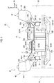
- FIGS. 1 and 2 there is a first feature in the disposition of a "motor 42", an “electric power distribution unit 44", a “water heating heater 46”, and a “DC/AC inverter 48 (hereinafter referred to as an inverter 48)" as an electric power conversion unit, which configure the power unit 10. Further, there is a second feature in the configuration of a "mounting part 50" to which the electric power distribution unit 44 and the water heating heater 46 are mounted.
- the configurations of the power unit 10 and the mounting part 50 configuring the main part of this embodiment will be described in detail.
- the motor 42 is provided with a housing 52 configuring an outer shell thereof, and a motor main body portion, a counter gear mechanism, and a differential gear mechanism, which are not shown, are disposed inside the housing 52.
- the motor main body portion is driven by electric power that is supplied thereto, and the driving force of the motor main body portion is transmitted to a pair of drive shafts 54 through the counter gear mechanism and the differential gear mechanism to drive "drive wheels 56 (front wheels)".
- the housing 52 is configured to include a first accommodation portion 52A configuring a portion on the left side in the vehicle width direction of the vehicle of the housing 52 and a second accommodation portion 52B configuring a portion on the right side in the vehicle width direction of the vehicle of the housing 52.
- the motor main body portion and a main portion of the differential gear mechanism are accommodated in the first accommodation portion 52A, and a main portion of the counter gear mechanism is accommodated in the second accommodation portion 52B.
- a mount bracket 58 is provided at each of both sides in the vehicle width direction of the vehicle of the housing 52.
- the mount bracket 58 is configured to include a mounting part 58A mounted to the housing 52 by a mounting member (not shown), and a support portion 58B supported on the suspension member main body portion 22A. Further, a through portion 60 penetrating in the up-down direction of the vehicle is formed in the support portion 58B, and a bush 61 made of an elastic body such as rubber is mounted in the through portion 60.
- the mount bracket 58 is mounted to the suspension member main body portion 22A through the bush 61, whereby a state where the motor 42 is supported on the suspension member 22 is created.
- the electric power distribution unit 44 is disposed on the upper side of the vehicle of the second accommodation portion 52B of the motor 42
- the inverter 48 is disposed on the upper side of the vehicle of the first accommodation portion 52A of the motor 42
- the water heating heater 46 is disposed on the upper side of the vehicle of the inverter 48.
- the electric power distribution unit 44 includes a housing 62 formed in a box shape having a substantially rectangular parallelepiped outer shape, and a plurality of electronic devices (not shown), that is, a high voltage junction box, a DC charging relay, an AC charger, and a DC/DC inverter, built in the housing 62.
- the electric power distribution unit 44 is electrically connected to a "charging port 64" as a connection portion through a "wire harness 66" as a side portion side wire harness, as shown in FIGS. 3 and 4 .
- the charging port 64 is provided in a "fender portion 68" configuring a part on the design surface side in the side portion 28 in the vehicle width direction of the vehicle on the right side in the vehicle width direction of the vehicle. Then, the electric power distribution unit 44 is disposed further on the charging port 64 side than the inverter 48, that is, on the right side in the vehicle width direction of the vehicle.
- the electric power distribution unit 44 is electrically connected to the inverter 48 through a "wire harness 70" as a power unit side wire harness and to the water heating heater 46 through a wire harness 72. Further, the electric power distribution unit 44 is made so as to supply (distribute) electric power supplied from an external power supply such as a charging station (not shown) through the charging port 64 to a "main battery 74 (an internal power supply)" as a power supply. Then, the electric power stored in the main battery 74 can be distributed to the inverter 48 and the water heating heater 46 by the electric power distribution unit 44.
- an external power supply such as a charging station (not shown)
- main battery 74 an internal power supply
- the electric power distribution unit 44 can also distribute electric power to an air conditioner compressor 76 and a "DC/AC inverter 78 (hereinafter referred to as an inverter 78)" as an electric power conversion unit disposed on the rear side of the vehicle.
- an air conditioner compressor 76 and a "DC/AC inverter 78 (hereinafter referred to as an inverter 78)" as an electric power conversion unit disposed on the rear side of the vehicle.
- the water heating heater 46 is configured to include a housing 80 formed in a box shape having an outer shape smaller than that of the housing 62 and a plurality of electronic devices (not shown) built in the housing 80, and is made to be capable of warming air that is blown to the inside of a vehicle cabin.
- the water heating heater 46 is made to be capable of warming water (heating medium) flowing toward a heater core (not shown) through a pipe connected to the heater core by being driven by electric power that is supplied thereto. Then, air is blown from a blower (not shown) to the inside of the vehicle cabin via the heater core, whereby warm air can be sent into the vehicle cabin. Further, as shown in FIG. 2 , the water heating heater 46 is disposed at a position overlapping the electric power distribution unit 44 when viewed from the vehicle width direction of the vehicle, more specifically, at a position where the outer periphery of the water heating heater 46 is entirely within the outer periphery of the electric power distribution unit 44.
- the inverter 48 is configured to include a housing 82 formed in a box shape having an outer shape smaller than that of the housing 62 and larger than that of the housing 80, and a plurality of electronic devices (not shown) built in the housing 82, and is made to be capable of converting the supplied electric power so as to be capable of being supplied to the motor 42. Specifically, the inverter 48 is made to convert a direct current from the main battery 74 or the like into an alternating current and allow the alternating current to flow to the motor 42.
- the inverter 78 also has the same configuration as the inverter 48, and the inverter 78 is made to be capable of converting the supplied electric power so as to be capable of being supplied to a motor 84 capable of transmitting a driving force to drive wheels (rear wheels) (not shown) on the rear side of the vehicle.
- the inverter 48 is mounted on an upper wall portion 52A1 configuring a portion on the upper side of the vehicle of the first accommodation portion 52A of the housing 52.
- the upper wall portion 52A1 is inclined on a downhill slope from the rear side of the vehicle toward the front side of the vehicle, the inverter 48 is disposed along the upper wall portion 52A1, and four corners of the housing 82 are fixed to the housing 52 with bolts 86 (fastening members) (refer to FIG. 6 ).
- bolts 86 fastening members
- the electric power distribution unit 44 described above is disposed at a position where the portion on the lower side of the vehicle of the electric power distribution unit 44 overlaps the portion on the upper side of the vehicle of the inverter 48 when viewed from the vehicle width direction of the vehicle. This can also be regarded as a part of the electric power distribution unit 44 being located at the same height as a part of the inverter 48 in the up-down direction of the vehicle.
- a "connector 88" of the inverter 48 as an electric power conversion unit side connector is provided on the lower side of the vehicle of the inverter 48, and the connector 88 is electrically connected to an electronic device in the housing 82 of the inverter 48.
- a recessed portion 90 is provided in the upper wall portion 52A1 of the housing 52 of the motor 42, and a “connector 94" of the motor 42 as a motor side connector is fixed to the inside of the recessed portion 90 through a spacer 92.
- the connector 94 is electrically connected to the electronic device in the housing 52 and is electrically connected to the connector 88 by being coupled to the connector 88.
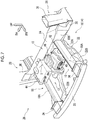
- the mounting part 50 includes a main body portion 96 and a reinforcing plate portion 98.
- the main body portion 96 is formed by bending a metal plate material at a plurality of locations and is configured to include a placing portion 96A on which the electric power distribution unit 44 is placed, a placing portion 96B on which the water heating heater 46 is placed, and a pair of mounting piece portions 96C.
- the placing portion 96A has a plate shape extending in the vehicle width direction of the vehicle and the front-rear direction of the vehicle with a plate thickness direction thereof being in the up-down direction of the vehicle, and a plurality of weld nuts (not shown) is provided on the surface on the lower side of the vehicle of the placing portion 96A. Then, fastening members such as bolts (not shown) inserted into the housing 62 from the upper side of the vehicle are fastened to the weld nuts of the placing portion 96A in a state where the electric power distribution unit 44 is placed on the placing portion 96A, whereby the electric power distribution unit 44 is fixed to the placing portion 96A.
- the placing portion 96B has a plate shape extending in the vehicle width direction of the vehicle and the front-rear direction of the vehicle with a plate thickness direction thereof being in the up-down direction of the vehicle, and a plurality of weld nuts (not shown) is provided on the surface on the lower side of the vehicle of the placing portion 96B. Further, the placing portion 96B is disposed on the left side in the vehicle width direction of the vehicle and the upper side of the vehicle with respect to the placing portion 96A.
- connection portion 96D is provided with an insertion portion (not shown) into which the wire harness 70 is inserted.
- Each of the mounting piece portions 96C has a plate shape extending in the up-down direction of the vehicle and the front-rear direction of the vehicle with a plate thickness direction thereof being in the vehicle width direction of the vehicle, and a plurality of insertion portions (not shown) is formed in the mounting piece portion 96C. Further, a peripheral edge portion on the lower side of the vehicle of the mounting piece portion 96C on the right side in the vehicle width direction of the vehicle is connected to a peripheral edge portion on the outer side in the vehicle width direction of the vehicle of the placing portion 96A by a connection portion 96E extending from the peripheral edge portion on the lower side of the vehicle of the mounting piece portion 96C toward the inner side in the vehicle width direction of the vehicle and the lower side of the vehicle.
- a peripheral edge portion on the upper side of the vehicle of the mounting piece portion 96C on the left side in the vehicle width direction of the vehicle is connected to a peripheral edge portion on the outer side in the vehicle width direction of the vehicle of the placing portion 96B by a connection portion 96F extending from the peripheral edge portion on the upper side of the vehicle of the mounting piece portion 96C toward the inner side in the vehicle width direction of the vehicle and the lower side of the vehicle.
- the reinforcing plate portion 98 is formed in a trapezoidal plate shape that is widened in width toward the lower side of the vehicle from the upper side of the vehicle when viewed from the front-rear direction of the vehicle.
- a peripheral edge portion on the inner side in the vehicle width direction of the vehicle of the reinforcing plate portion 98 is joined to the surface on the lower side of the vehicle of the connection portion 96F by a joining portion (not shown) by welding or the like, and a peripheral edge portion on the outer side in the vehicle width direction of the vehicle of the reinforcing plate portion 98 is joined to the surface on the inner side in the vehicle width direction of the vehicle of the mounting piece portion 96C on the left side in the vehicle width direction of the vehicle by a joining portion (not shown) by welding or the like.
- the vertical wall portion 40B of the suspension tower 40 is provided with a mounting wall portion 40B1 integrally formed with the vertical wall portion 40B and extending in the up-down direction of the vehicle and the front-rear direction of the vehicle with a plate thickness direction thereof being in the vehicle width direction of the vehicle. Further, a weld nut (not shown) corresponding to the insertion portion of the mounting piece portion 96C is provided on the surface on the outer side in the vehicle width direction of the vehicle of the mounting wall portion 40B 1.
- a bolt 100 (a fastening member) is inserted into the insertion portion of the mounting piece portion 96C from the inner side in the vehicle width direction of the vehicle and fastened to the weld nut of the mounting wall portion 40B1, whereby the mounting part 50 is fixed to the suspension towers 40 in a state of being laid in the vehicle width direction of the vehicle between the suspension towers 40.
- a predetermined gap is secured between the surface on the lower side of the vehicle of the mounting part 50, and the inverter 48 and the motor 42, and thus the mounting part 50 does not interfere with the inverter 48 and the motor 42 during traveling or the like of the vehicle 26.
- the electric power supplied from an external power supply such as a charging station or an internal power supply such as the main battery 74 is distributed to the inverter 48 by the electric power distribution unit 44. Further, the electric power supplied from the electric power distribution unit 44 to the inverter 48 is converted by the inverter 48 so as to be capable of being supplied to the motor 42 disposed in the power unit room 12. Then, the motor 42 supplied with the electric power from the inverter 48 is driven, whereby the driving force is transmitted to the drive wheels 56, so that the drive wheels 56 are driven.
- the inverter 48 is disposed on the upper side of the vehicle of the motor 42, and the electric power distribution unit 44 is disposed at a position overlapping the inverter 48 when viewed from the vehicle width direction of the vehicle.
- the space needed for accommodating the motor 42, the inverter 48, and the electric power distribution unit 44 can be suppressed from becoming large in the up-down direction of the vehicle, by an amount corresponding to the overlap of the electric power distribution unit 44 and the inverter 48.
- the motor 42, the inverter 48, and the electric power distribution unit 44 are disposed in the power unit room 12, it is possible to suppress the power unit room 12 from becoming large in the up-down direction of the vehicle. As a result, it is possible to suppress an increase in the height of the vehicle in the front portion of the vehicle 26, thereby contributing to improvement in the design of the vehicle 26.
- the electric power distribution unit 44 is disposed at a position overlapping the inverter 48 when viewed from the vehicle width direction of the vehicle, and therefore, the space needed for accommodating the motor 42, the inverter 48, and the electric power distribution unit 44 can be suppressed from becoming large in the front-rear direction of the vehicle, by an amount corresponding to the overlap of the electric power distribution unit 44 and the inverter 48.
- the motor 42, the inverter 48, and the electric power distribution unit 44 are disposed in the power unit room 12, it is possible to suppress the power unit room 12 from becoming large in the front-rear direction of the vehicle.
- the electric power distribution unit 44 is supported by the suspension tower 40 configuring a part of the side portion 28 in the vehicle width direction of the vehicle through the mounting part 50, and therefore, it is possible to support the electric power distribution unit 44 in a stable state.
- the mounting part 50 is laid in the vehicle width direction of the vehicle between the suspension towers 40, and the suspension towers 40 are connected to each other in the vehicle width direction of the vehicle by the mounting part 50. For this reason, during traveling or the like of the vehicle 26, the relative displacement in the vehicle width direction of the vehicle between the suspension towers 40 is suppressed, and as a result, the twist of the vehicle body 14 is suppressed. That is, the mounting part 50 functions as a stabilizer of the vehicle body 14. Therefore, it is possible to reduce the influence of the deformation of the vehicle body 14 on the electric power distribution unit 44 during traveling or the like of the vehicle 26.
- the charging port 64 for charging to which electric power is supplied from an external power supply is provided in the fender portion 68 configuring a part of the design surface side of the side portion 28 in the vehicle width direction of the vehicle.
- the charging port 64 and the electric power distribution unit 44 are electrically connected to each other by the wire harness 66.
- the electric power distribution unit 44 is disposed closer to the charging port 64 than the inverter 48, and thus it is possible to shorten the wire harness 66, compared to a configuration in which the electric power distribution unit 44 and the inverter 48 are disposed to be arranged in a row in the up-down direction of the vehicle. Therefore, it is possible to reduce an electric power loss occurring when electric power is supplied from the charging port 64 to the electric power distribution unit 44, while suppressing the power unit room 12 from becoming large in the up-down direction of the vehicle.
- the inverter 48 and the electric power distribution unit 44 are electrically connected to each other by the wire harness 70.
- the inverter 48 since the inverter 48 is mounted on the motor 42 supported by the suspension member 22 and the electric power distribution unit 44 is fixed to the mounting part 50 fixed to the suspension towers 40, it is conceivable that a vibration mode is different between the inverter 48 and the electric power distribution unit 44 during traveling or the like of the vehicle 26.
- the inverter 48 and the electric power distribution unit 44 are electrically connected to each other by the wire harness 70, as described above, and therefore, even though the vibration mode of the inverter 48 and the vibration mode of the electric power distribution unit 44 are different from each other, it is possible to maintain the electrical connection state between the inverter 48 and the electric power distribution unit 44 in a stable state. As a result, it is possible to stably supply electric power from the electric power distribution unit 44 to the inverter 48.
- the water heating heater 46 is disposed at a position overlapping the electric power distribution unit 44 when viewed from the vehicle width direction of the vehicle. In this way, compared to such a configuration that the water heating heater 46 is disposed on the upper side of the vehicle of the electric power distribution unit 44, the space needed for accommodating the motor 42, the inverter 48, the electric power distribution unit 44, and the water heating heater 46 can be suppressed from becoming large in the up-down direction of the vehicle.
- the water heating heater 46 is disposed in the power unit room 12, it is possible to suppress the power unit room 12 from becoming large in the up-down direction of the vehicle.
- FIGS. 8 and 9 a second embodiment of the power unit structure for a vehicle will be described using FIGS. 8 and 9 .
- the same constituent portions as those of the first embodiment described above are denoted by the same reference numerals, and description thereof is omitted.
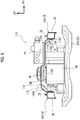
- a power unit 110 according to this embodiment basically has the same configuration as the power unit 10 according to the first embodiment. However, the power unit 110 is characterized in that a "mounting part 112" that supports the electric power distribution unit 44 and the water heating heater 46 is mounted to the front side members 18.
- the mounting part 112 includes a main body portion 114 and reinforcing plate portions 116, 118.
- the main body portion 114 basically has the same configuration as the main body portion 96 and is configured to include a placing portion 114A on which the electric power distribution unit 44 is placed, a placing portion 114B on which the water heating heater 46 is placed, and a pair of mounting piece portions 114C.
- Each of the mounting piece portions 114C has a plate shape extending in the up-down direction of the vehicle and the front-rear direction of the vehicle with a plate thickness direction thereof being in the vehicle width direction of the vehicle.
- a peripheral edge portion on the upper side of the vehicle of the mounting piece portion 114C on the right side in the vehicle width direction of the vehicle is connected to a peripheral edge portion on the outer side in the vehicle width direction of the vehicle of the placing portion 114A by a connection portion 114D extending from the peripheral edge portion on the upper side of the vehicle of the mounting piece portion 114C toward the inner side in the vehicle width direction of the vehicle and the upper side of the vehicle.
- a peripheral edge portion on the upper side of the vehicle of the mounting piece portion 114C on the left side in the vehicle width direction of the vehicle is connected to a peripheral edge portion on the outer side in the vehicle width direction of the vehicle of the placing portion 114B by a connection portion 114E extending from the peripheral edge portion on the upper side of the vehicle of the mounting piece portion 114C toward the inner side in the vehicle width direction of the vehicle and the lower side of the vehicle.
- the reinforcing plate portion 116 has a plate shape extending so as to be substantially parallel to the connection portion 114D. An end portion on the outer side in the vehicle width direction of the vehicle of the reinforcing plate portion 116 is joined to the surface on the inner side in the vehicle width direction of the vehicle of the mounting piece portion 114C on the right side in the vehicle width direction of the vehicle by a joining portion (not shown) by welding or the like, and an end portion on the inner side in the vehicle width direction of the vehicle of the reinforcing plate portion 116 is joined to the surface on the lower side of the vehicle of the placing portion 114A by a joining portion (not shown) by welding or the like.
- the reinforcing plate portion 118 has a plate shape extending so as to be substantially parallel to the connection portion 114E.
- An end portion on the outer side in the vehicle width direction of the vehicle of the reinforcing plate portion 118 is joined to the surface on the inner side in the vehicle width direction of the vehicle of the mounting piece portion 114C on the left side in the vehicle width direction of the vehicle by a joining portion (not shown) by welding or the like, and an end portion on the inner side in the vehicle width direction of the vehicle of the reinforcing plate portion 118 is joined to the surface on the lower side of the vehicle of the placing portion 114B by a joining portion (not shown) by welding or the like.
- insertion portions 120 into each of which a “stud bolt 124" as a shaft part protruding from the front portion 18A of the front side member 18 toward the inner side in the vehicle width direction of the vehicle is inserted in an axial direction of the stud bolt 124, are provided at a plurality of positions spaced apart from each other in the front-rear direction of the vehicle in the mounting piece portion 114C.
- the insertion portion 120 has a slit shape that extends from a central portion in the up-down direction of the vehicle of the mounting piece portion 114C to an end portion on the lower side of the vehicle of the mounting piece portion 114C when viewed from the vehicle width direction of the vehicle. Then, a nut 125 is fastened to the stud bolt 124 from the inner side in the vehicle width direction of the vehicle in a state where the stud bolt 124 is inserted into the end portion on the upper side of the vehicle of the insertion portion 120, whereby the mounting part 112 is mounted to the front side member 18.
- this embodiment is characterized in that "fuse portions 126, 128" and a slit portion 130 are provided adjacent to the insertion portion 120 in the mounting piece portion 114C.
- a part on the front side of the vehicle of the insertion portion 120 in a peripheral edge portion thereof is opened at the end portion on the upper side of the vehicle of the insertion portion 120.
- the slit portion 130 extending in the front-rear direction of the vehicle is provided continuously with the insertion portion 120 on the front side of the vehicle in the end portion on the upper side of the vehicle of the insertion portion 120.
- the length (width) in the up-down direction of the vehicle of the slit portion 130 is set to a length into which the stud bolt 124 can be inserted.
- the fuse portions 126, 128 are provided in a pair in the up-down direction of the vehicle at a boundary portion between the insertion portion 120 and the slit portion 130 and configure a part of the peripheral edge portion of the insertion portion 120. Then, the fuse portion 126 on the upper side of the vehicle has a substantially triangular shape that is reduced in width toward the lower side of the vehicle from the upper side of the vehicle when viewed from the vehicle width direction of the vehicle. On the other hand, the fuse portion 128 on the lower side of the vehicle has a substantially triangular shape that is reduced in width toward the upper side of the vehicle from the lower side of the vehicle when viewed from the vehicle width direction of the vehicle.
- the same operation and effect as those in the first embodiment described above except for the operation and effect by the configuration in which the mounting part 50 is mounted to the suspension towers 40 are exhibited.
- the mounting part 112 is laid in the vehicle width direction of the vehicle between the front side members 18. That is, a state is created where a rigid frame structure is configured by the bumper R/F 20, the front side members 18, and the mounting part 112.
- each of the front side members 18 is provided with the stud bolt 124 protruding toward the inner side in the vehicle width direction of the vehicle, and the mounting part 112 to which the electric power distribution unit 44 is mounted is mounted to the stud bolt 124.
- the insertion portion 120 is provided in the mounting part 112 and the stud bolt 124 provided on the front side member 18 is inserted into the insertion portion 120. Further, the fuse portions 126, 128 are provided adjacent to the insertion portion 120 in the mounting part 112. Then, when the load F1 toward the front side of the vehicle, which is equal to or larger than a predetermined value, acts on the mounting part 112, the fuse portions 126, 128 are plastically deformed under the load from the stud bolt 124, so that the relative displacement in the front-rear direction of the vehicle between the stud bolt 124 and the insertion portion 120 is permitted, and eventually, the relative displacement between the front side member 18 and the mounting part 112 is permitted.
- the mounting part 112 is displaced toward the rear side of the vehicle, and thus it is possible to suppress the mounting part 112 from serving as resistance to the crushed deformation. Therefore, it is possible to secure a crushing margin against the collision load F2 from the front side of the vehicle of the front side member 18 while supporting the electric power distribution unit 44 in a stable state.
- the insertion portion 120 is formed in a slit shape extending in the up-down direction of the vehicle. For this reason, when a subassembly configured to include the electric power distribution unit 44, the water heating heater 46, and the mounting part 112 is mounted to the vehicle body 14, it is possible to use the insertion portion 120 and the stud bolt 124 as guides for the subassembly.
- FIG. 10 a third embodiment of the power unit structure for a vehicle will be described using FIG. 10 .
- the same constituent portions as those of the first embodiment described above are denoted by the same reference numerals, and description thereof is omitted.
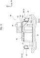
- a power unit 140 according to this embodiment basically has the same configuration as the power unit 10 according to the first embodiment. However, there is a first feature in that the power unit 140 is not provided with the water heating heater 46 according to the specifications of the vehicle 26. Further, there is a second feature in that the electric power distribution unit 44 is mounted in a cantilevered state to the front side member 18 on the right side in the vehicle width direction of the vehicle by a "mounting part 142".
- the mounting part 142 includes a main body portion 144 and a reinforcing plate portion 146.
- the main body portion 144 includes a placing portion 144A having the same configuration as the placing portion 96A, and a mounting piece portion 144B.
- the mounting piece portion 144B is formed in a plate shape extending in the up-down direction of the vehicle and the front-rear direction of the vehicle with a plate thickness direction thereof being in the vehicle width direction of the vehicle, and is fixed to the front side member 18 by a mounting member (not shown) or a joining portion by welding or the like.
- a configuration is also acceptable in which the insertion portion 120, the slit portion 130, and the fuse portions 126, 128 are provided in the mounting piece portion 144B and the mounting piece portion 144B is mounted to the front side member 18 by using the stud bolt 124 provided on the front side member 18.
- the reinforcing plate portion 146 is formed in a plate shape extending from an end portion on the lower side of the vehicle of the mounting piece portion 144B toward a central portion of the placing portion 144A.
- An end portion on the outer side in the vehicle width direction of the vehicle of the reinforcing plate portion 146 is joined to the surface on the inner side in the vehicle width direction of the vehicle of the mounting piece portion 144B by a joining portion (not shown) by welding or the like, and an end portion on the inner side in the vehicle width direction of the vehicle of the reinforcing plate portion 146 is joined to the surface on the lower side of the vehicle of the placing portion 144Aby a joining portion (not shown) by welding or the like.
- FIG. 11 a fourth embodiment of the power unit structure for a vehicle will be described using FIG. 11 .
- the same constituent portions as those of the first embodiment described above are denoted by the same reference numerals, and description thereof is omitted.
- a power unit 160 according to this embodiment basically has the same configuration as the power unit 10 according to the first embodiment. However, similar to the third embodiment, there is a first feature in that the power unit 160 is not provided with the water heating heater 46 according to the specifications of the vehicle 26. Further, there is a second feature in that the electric power distribution unit 44 is mounted to the motor 42 through a "mounting part 162".
- the mounting part 162 is configured to include a placing plate portion 164 having the same configuration as the placing portion 96A, support plate portions 166, 168, and a reinforcing plate portion 170.
- the support plate portion 166 is disposed on the lower side of the vehicle of the end portion on the inner side in the vehicle width direction of the vehicle of the placing plate portion 164 and extends in the up-down direction of the vehicle with a plate thickness direction thereof being in the vehicle width direction of the vehicle.
- An end portion on the upper side of the vehicle of the support plate portion 166 is joined to the placing plate portion 164 by a joining portion (not shown) by welding or the like, and an end portion on the lower side of the vehicle of the support plate portion 166 is mounted to the motor 42 by a mounting member (not shown) or the like.
- the support plate portion 168 is disposed on the lower side of the vehicle of a central portion of the placing plate portion 164, and extends in the up-down direction of the vehicle with a plate thickness direction thereof being in the vehicle width direction of the vehicle.
- An end portion on the upper side of the vehicle of the support plate portion 168 is joined to the placing plate portion 164 by a joining portion (not shown) by welding or the like, and an end portion on the lower side of the vehicle of the support plate portion 168 is mounted to the motor 42 by a mounting member (not shown) or the like.
- the reinforcing plate portion 170 extends from an end portion on the lower side of the vehicle of the support plate portion 168 to an end portion on the outer side in the vehicle width direction of the vehicle of the placing plate portion 164 and is joined to the support plate portion 168 and the placing plate portion 164 by a joining portion (not shown) by welding or the like.
- the configuration inside the power unit room 12 can be simplified according to the specifications of the vehicle 26.
- the motor 42, the inverter 48, and the electric power distribution unit 44 are made into a sub-assembly, whereby it is possible to reduce the number of processes when disposing these in the power unit room 12.
Landscapes
- Engineering & Computer Science (AREA)
- Mechanical Engineering (AREA)
- Transportation (AREA)
- Power Engineering (AREA)
- Chemical & Material Sciences (AREA)
- Combustion & Propulsion (AREA)
- Life Sciences & Earth Sciences (AREA)
- Sustainable Development (AREA)
- Sustainable Energy (AREA)
- Physics & Mathematics (AREA)
- Thermal Sciences (AREA)
- Arrangement Or Mounting Of Propulsion Units For Vehicles (AREA)
- Body Structure For Vehicles (AREA)
- Electric Propulsion And Braking For Vehicles (AREA)
Abstract
Description
- The invention relates to a power unit structure for a vehicle.
- Japanese Unexamined Patent Application Publication No.
2011-020628 JP 2011-020628 A - On the other hand, in a strong electricity box structure of an electric vehicle described in Japanese Unexamined Patent Application Publication No.
09-277840 JP 09-277840 A - Incidentally, when a configuration in which the related art described in
JP 09-277840 A JP 2011-020628 A - However, when the motor, the inverter, and the junction box are all disposed to be arranged in a row in the up-down direction of the vehicle, it is conceivable that a power unit room in which these are accommodated becomes large in the up-down direction of the vehicle.
- The invention provides a power unit structure for a vehicle, in which, even though a motor, an electric power conversion unit, and an electric power distribution unit are disposed in a power unit room, it is possible to suppress the power unit room from becoming large in the up-down direction of the vehicle.
- An aspect of the invention relates to a power unit structure for a vehicle. The power unit structure includes a motor disposed in a power unit room of the vehicle and configured to transmit a driving force to drive wheels of the vehicle, an electric power converter disposed in the power unit room of the vehicle, and an electric power distributor disposed in the power unit room of the vehicle. The electric power converter is configured to convert supplied electric power into electric power to be supplied to the motor and is disposed on an upper side of the motor. The electric power distributor is configured to distribute electric power supplied from a power supply to the electric power converter and is disposed at a position where at least a part of the electric power distributor overlaps the electric power converter in an up-down direction of the vehicle when viewed from a front-rear direction of the vehicle or a vehicle width direction of the vehicle.
- According to the aspect of the invention, the electric power supplied from the power supply is distributed to the electric power converter by the electric power distributor. Further, the electric power supplied from the electric power distributor to the electric power converter is converted in the electric power converter so as to be supplied to the motor disposed in the power unit room. Then, the motor supplied with the electric power from the electric power converter is driven, and the driving force is transmitted to the drive wheels to drive the drive wheels.
- Incidentally, when the motor, the electric power converter, and the electric power distributor are all disposed to be arranged in a row in the up-down direction of the vehicle, it is conceivable that a space needed for accommodating them becomes large in the up-down direction of the vehicle.
- Here, in the aspect of the invention, the electric power converter is disposed on the upper side of the motor and the electric power distributor is disposed at a position overlapping the electric power converter when viewed from the front-rear direction of the vehicle or the vehicle width direction of the vehicle. For this reason, compared to a configuration in which the motor, the electric power converter, and the electric power distributor are all disposed to be arranged in a row in the up-down direction of the vehicle, the space needed for accommodating the motor, the electric power converter, and the electric power distributor can be suppressed from becoming large in the up-down direction of the vehicle, by an amount corresponding to the overlap of the electric power distributor and the electric power converter.
- In the power unit structure according to the aspect of the invention, the electric power distributor may be disposed at a position where at least a part of the electric power distributor overlaps the electric power converter when viewed from the vehicle width direction of the vehicle.
- According to the aspect of the invention, since the electric power distributor is disposed at a position where at least a part of the electric power distributor overlaps the electric power converter when viewed from the vehicle width direction of the vehicle, the space needed for accommodating the motor, the electric power converter, and the electric power distributor can be suppressed from becoming large in the front-rear direction of the vehicle, by an amount corresponding to the overlap of the electric power distributor and the electric power converter.
- In the power unit structure according to the aspect of the invention, the electric power distributor may be mounted on a mounting part provided on a vehicle body constituent member of the vehicle. The vehicle body constituent member may configure a part of a side portion in the vehicle width direction of the vehicle.
- According to the aspect of the invention, the electric power distributor is supported by the vehicle body constituent member configuring a part of a side portion in the width direction of the vehicle through the mounting part.
- In the power unit structure according to the aspect of the invention, the vehicle body constituent member may be a pair of suspension towers of the vehicle. The mounting part may be laid in the vehicle width direction of the vehicle between the suspension towers.
- According to the aspect of the invention, the mounting part is laid in the vehicle width direction of the vehicle between the suspension towers, and these suspension towers are connected to each other in the vehicle width direction of the vehicle by the mounting part. For this reason, relative displacement in the vehicle width direction of the vehicle between the suspension towers is suppressed during traveling or the like of the vehicle, and as a result, the twist of the vehicle body is suppressed.
- In the power unit structure according to the aspect of the invention, the vehicle body constituent member may be a pair of front side members of the vehicle. The mounting part may be laid in the vehicle width direction of the vehicle between the front side members.
- According to the aspect of the invention, the mounting part is laid in the vehicle width direction of the vehicle between the front side members. For this reason, when the front side member is crushed and deformed due to a collision load from the front side of the vehicle, the relative displacement in the vehicle width direction of the vehicle between the front side members is suppressed by the mounting part. As a result, when the front side member is crushed and deformed, it is possible to suppress the front side member from being bent and deformed in the vehicle width direction of the vehicle.
- In the power unit structure according to the aspect of the invention, each of the front side members may include a shaft part that protrudes to an inner side in the vehicle width direction of the vehicle and is used for mounting of the mounting part. The mounting part may include an insertion portion configured such that the shaft part is inserted into the insertion portion in an axial direction of the shaft part, and a fuse portion that is provided adjacent to the insertion portion and permits relative displacement in the front-rear direction of the vehicle between the shaft part and the insertion portion by being plastically deformed when a load having a magnitude equal to or larger than a predetermined value, toward a front side of the vehicle, acts on the mounting part.
- According to the aspect of the invention, each of the front side members is provided with the shaft part protruding to the inner side in the vehicle width direction of the vehicle, and the mounting part to which the electric power distributor is mounted is mounted to the shaft part.
- Incidentally, when the front side member is crushed and deformed due to the collision load from the front side of the vehicle, it is conceivable that the front side member is not easily crushed and deformed at the mounting place of the mounting part in the front side member.
- Here, in the aspect of the invention, the insertion portion is provided in the mounting part, and the shaft part provided at the front side member is inserted into the insertion portion. Further, the mounting part has the fuse portion provided adjacent to the insertion portion. Then, when a load which is equal to or larger than a predetermined value, toward the front side of the vehicle, acts on the mounting part, the fuse portion is plastically deformed, so that the relative displacement in the front-rear direction of the vehicle between the shaft part and the insertion portion is permitted, and eventually, the relative displacement between the front side member and the mounting part is permitted.
- For this reason, when the front side member is crushed and deformed due to the collision load from the front side of the vehicle, even though the crushed deformation reaches the place where the shaft part is provided, the mounting part is displaced toward the rear side of the vehicle, and thus it is possible to suppress the mounting part from serving as resistance to the crushed deformation.
- In the power unit structure according to the aspect of the invention, a connection portion for charging, to which electric power is supplied from an external power supply as the power supply, may be disposed at a fender portion configuring a part on a design surface side of the side portion in the vehicle width direction of the vehicle. The electric power distributor may be disposed at a position closer to the connection portion than the electric power converter, and the connection portion and the electric power distributor may be connected to each other by a wire harness.
- According to the aspect of the invention, the connection portion for charging to which electric power is supplied from the external power supply is disposed at the fender portion configuring a part on the design surface side of the side portion in the vehicle width direction of the vehicle. Further, the connection portion and the electric power distributor are connected to each other by the wire harness. Here, in the aspect of the invention, the electric power distributor is disposed at a position closer to the connection portion than the electric power converter, and thus the wire harness can be shortened compared to a configuration in which the electric power distributor and the electric power converter are disposed to be arranged in a row in the up-down direction of the vehicle.
- In the power unit structure according to the aspect of the invention, the electric power converter may be fixed to the motor.
- According to the aspect of the invention, the electric power converter is fixed to the motor, and the electric power converter and the motor can be mounted to the vehicle body in a state of being subassembled.
- In the power unit structure according to the aspect of the invention, the motor may include a motor side connector that is disposed on the upper side of the motor, and the electric power converter may include an electric power converter side connector that is disposed on the lower side of the electric power converter and configured to be electrically connected to the motor side connector.
- According to the aspect of the invention, when the electric power converter is fixed to the motor, the motor side connector on the upper side of the motor and the electric power converter side connector on the lower side of the electric power converter are coupled to each other, whereby the motor and the electric power converter can be electrically connected to each other.
- In the power unit structure according to the aspect of the invention, the electric power converter and the electric power distributor may be electrically connected to each other by a power unit side wire harness.
- According to the aspect of the invention, since the electric power converter and the electric power distributor are electrically connected to each other by the power unit side wire harness, even though a vibration mode of the electric power converter and a vibration mode of the electric power distributor are different from each other, it is possible to maintain the electrical connection state between the electric power converter and the electric power distributor in a stable state.
- The power unit structure according to the aspect of the invention may further include a water heating heater disposed on the upper side of the electric power converter. The water heating heater may be configured to receive electric power that is supplied from the electric power distributor. The water heating heater may be disposed at a position overlapping the electric power distributor when viewed from the vehicle width direction of the vehicle.
- According to the aspect of the invention, electric power is supplied to the water heating heater to drive the water heating heater, whereby it is possible to warm air that is blown to the inside of a vehicle cabin. Further, in the aspect of the invention, the water heating heater is disposed at a position overlapping the electric power distributor when viewed from the vehicle width direction of the vehicle. In this way, compared to such a configuration that the water heating heater is disposed on the upper side of the electric power distributor, it is possible to suppress the space needed for accommodating the motor, the electric power converter, the electric power distributor, and the water heating heater from becoming large in the up-down direction of the vehicle.
- As described above, the power unit structure according to the aspect of the invention has an excellent effect that, even though the motor, the electric power converter, and the electric power distributor are disposed in the power unit room, it is possible to suppress the power unit room from becoming large in the up-down direction of the vehicle.
- Further, the power unit structure according to the aspect of the invention has an excellent effect that, even though the motor, the electric power converter, and the electric power distributor are disposed in the power unit room, it is possible to suppress the power unit room from becoming large in the front-rear direction of the vehicle.
- Further, the power unit structure according to the aspect of the invention has an excellent effect that it is possible to support the electric power distributor in a stable state.
- Further, the power unit structure according to the aspect of the invention has an excellent effect that it is possible to reduce the influence of the deformation of the vehicle body on the electric power distributor during traveling or the like of the vehicle.
- Further, the power unit structure according to the aspect of the invention has an excellent effect that it is possible to secure the shock absorbing performance of the front side member while supporting the electric power distributor in a stable state.
- Further, the power unit structure according to the aspect of the invention has an excellent effect that it is possible to secure a crushing margin against the collision load from the front side of the vehicle of the front side member while supporting the electric power distributor in a stable state.
- Further, the power unit structure according to the aspect of the invention has an excellent effect that it is possible to reduce an electric power loss occurring when electric power is supplied from the connection portion for charging of the external power supply to the electric power distributor, while suppressing the power unit room from becoming large in the up-down direction of the vehicle.
- Further, the power unit structure according to the aspect of the invention has an excellent effect that it is possible to reduce the number of processes when disposing the motor and the electric power converter in the power unit room, while suppressing the power unit room from becoming large in the up-down direction of the vehicle.
- Further, the power unit structure according to the aspect of the invention has an excellent effect that it is possible to reduce the number of processes of work of assembling the motor and the electric power converter.
- Further, the power unit structure according to the aspect of the invention has an excellent effect that it is possible to stably supply electric power from the electric power distributor to the electric power converter.
- Further, the power unit structure according to the aspect of the invention has an excellent effect that, even though in addition to the motor, the electric power converter, and the electric power distributor, the water heating heater is disposed in the power unit room, it is possible to suppress the power unit room from becoming large in the up-down direction of the vehicle.
- Features, advantages, and technical and industrial significance of exemplary embodiments of the invention will be described below with reference to the accompanying drawings, in which like numerals denote like elements, and wherein:
-
FIG. 1 is a rear view showing the configurations of a power unit to which a power unit structure for a vehicle according to a first embodiment is applied and a vehicle body front portion, as viewed from the rear side of a vehicle; -
FIG. 2 is a side view (a view as viewed from the direction of anarrow 2 inFIG. 1 ) showing the configuration of the power unit to which the power unit structure for a vehicle according to the first embodiment is applied, as viewed from the outer side in a vehicle width direction of the vehicle; -
FIG. 3 is a rear view showing an electrical connection state of each constituent element in the power unit to which the power unit structure for a vehicle according to the first embodiment is applied, as viewed from the rear side of the vehicle; -
FIG. 4 is a block diagram showing an electrical connection state of the power unit to which the power unit structure for a vehicle according to a first embodiment is applied, and each constituent element disposed around the power unit; -
FIG. 5 is a perspective view (a view as viewed from the direction of anarrow 5 inFIG. 7 ) showing a relationship between a motor and an electric power conversion unit in the power unit to which the power unit structure for a vehicle according to the first embodiment is applied, as viewed from the outside rearward of the vehicle; -
FIG. 6 is a partial sectional view (a sectional view showing a state cut along line VI-VI ofFIG. 5 ) showing the relationship between the motor and the electric power conversion unit in the power unit to which the power unit structure for a vehicle according to the first embodiment is applied, as viewed from the outside rearward of the vehicle; -
FIG. 7 is a perspective view showing the configurations of the power unit to which the power unit structure for a vehicle according to the first embodiment is applied and the vehicle body front portion, as viewed from outside forward of the vehicle; -
FIG. 8 is rear view showing the configurations of a power unit to which a power unit structure for a vehicle according to a second embodiment is applied and the vehicle body front portion, as viewed from the rear side of the vehicle; -
FIG. 9 is a side view (a view as viewed from the direction of anarrow 9 inFIG. 8 ) showing a connection state between a mount and a front side member of the power unit to which the power unit structure for a vehicle according to the second embodiment is applied, as viewed from the inner side in the vehicle width direction of the vehicle; -
FIG. 10 is rear view showing the configurations of a power unit to which a power unit structure for a vehicle according to a third embodiment is applied and the vehicle body front portion, as viewed from the rear side of the vehicle; and -
FIG. 11 is rear view showing the configurations of a power unit to which a power unit structure for a vehicle according to a fourth embodiment is applied and the vehicle body front portion, as viewed from the rear side of the vehicle. - Hereinafter, a first embodiment of a power unit structure for a vehicle will be described using
FIGS. 1 to 7 . An arrow FR appropriately shown in each drawing indicates the front side of the vehicle, an arrow UP indicates the upper side of the vehicle, and an arrow RH indicates the right side in a vehicle width direction of the vehicle. - First, the configuration of a vehicle
body front portion 16 configuring a portion on the front side of the vehicle of avehicle body 14 having a "power unit room 12" in which apower unit 10 to which the power unit structure for a vehicle according to this embodiment is applied is disposed will be described usingFIG. 7 . - The vehicle
body front portion 16 includes a pair of "front side members 18", a bumper reinforcement 20 (hereinafter referred to as a "bumper R/F 20"), asuspension member 22, and adash panel 24, as vehicle body constituent members. - The
front side member 18 configures a part of a "side portion 28 in the vehicle width direction of the vehicle" in a "vehicle 26" and is disposed on the outer side in the vehicle width direction of the vehicle of thepower unit room 12. Thefront side member 18 is configured to include afront portion 18A extending in a front-rear direction of the vehicle, and akick portion 18B extending to be inclined on a downhill slope from the portion on the rear side of the vehicle of thefront portion 18A toward the rear side of the vehicle. - More specifically, as shown in
FIG. 1 , thefront portion 18A is configured to include a front portionouter portion 30 configuring a portion on the outer side in the vehicle width direction of the vehicle of thefront portion 18A, and a front portioninner portion 32 configuring a portion on the inner side in the vehicle width direction of the vehicle of thefront portion 18A, and has a closed cross-sectional structure in which a cross-sectional shape when viewed from the front-rear direction of the vehicle is a substantially rectangular frame shape. - The bumper R/
F 20 is disposed on the front side of the vehicle of thefront side member 18 with a longitudinal direction thereof being in the vehicle width direction of the vehicle, and is made of an extruded material of an aluminum alloy in which a cross-sectional shape when viewed from the longitudinal direction thereof is a rectangular frame shape divided into two parts in the up-down direction of the vehicle. Each of both end portions of the bumper R/F 20 is connected to an end portion on the front side of the vehicle of each of thefront side members 18 through acrush box 34, and the bumper R/F 20 is in a state of being laid in the vehicle width direction of the vehicle between thefront side members 18. - The
suspension member 22 is configured to include a suspension membermain body portion 22A configuring the main portion thereof and a pair of extendingportions 22B. The suspension membermain body portion 22A is formed in a substantially rectangular shape when viewed from the up-down direction of the vehicle, and a portion on the rear side of the vehicle of the suspension membermain body portion 22A is mounted to a portion on the rear side of the vehicle in thefront portion 18A of thefront side member 18 by a mounting member (not shown). - Further, a suspension arm (not shown) is mounted to each of the portions on the outer side in the vehicle width direction of the vehicle of the suspension member
main body portion 22A. An end portion on the lower side of the vehicle of a shock absorber (not shown) is connected to a tip portion of the suspension arm. - The extending
portion 22B extends from the portion on the front side of the vehicle of the suspension membermain body portion 22A toward the front side of the vehicle, and a portion on the tip side thereof is mounted to the portion on the front side of the vehicle in thefront portion 18A of thefront side member 18 by a mounting member (not shown). - On the other hand, a
front pillar 36 extending in the up-down direction of the vehicle is disposed on the outer side in the vehicle width direction of the vehicle of thefront side member 18. Thefront pillar 36 is connected to thekick portion 18B of thefront side member 18 through atorque box portion 38 on the lower side of the vehicle of thefront pillar 36. Then, thedash panel 24 is disposed on the rear side of the vehicle of thefront side member 18 and between thefront side members 18. - The
dash panel 24 is a press molded member extending in the vehicle width direction of the vehicle and the up-down direction of the vehicle and is disposed with a plate thickness direction being in the front-rear direction of the vehicle. The end portion on the outer side in the vehicle width direction of the vehicle of thedash panel 24 is joined to thefront pillar 36 by a joining portion (not shown) by welding or the like, and the surface on the front side of the vehicle of thedash panel 24 is joined to thekick portion 18B of thefront side member 18 by a joining portion (not shown) by welding or the like. - In this embodiment, the
power unit room 12 can be regarded as a space partitioned by the bumper R/F 20, thefront side members 18, and thedash panel 24 when viewed from the up-down direction of the vehicle. - On the other hand, as shown in
FIG. 1 , a "suspension tower 40" as a vehicle body constituent member configuring a part of theside portion 28 in the vehicle width direction of the vehicle is disposed on the outer side in the vehicle width direction of the vehicle of each of thefront side members 18. - The
suspension tower 40 is made of a press molded member configured to include a suspension towermain body portion 40A and avertical wall portion 40B. The suspension towermain body portion 40A configures the main portion of thesuspension tower 40, is opened on the lower side of the vehicle of the suspension towermain body portion 40A, and is formed in a box shape or a tubular shape in which the shock absorber described above and a part of a spring (not shown) mounted to the shock absorber can be accommodated in the interior thereof. The end portion on the upper side of the vehicle of the shock absorber is connected to the portion of the upper side of the vehicle of the suspension towermain body portion 40A. - The
vertical wall portion 40B extends from the portion on the inner side in the vehicle width direction of the vehicle of the suspension towermain body portion 40A toward the lower side of the vehicle, and the end portion on the lower side of the vehicle of thevertical wall portion 40B is joined to the portion on the upper side of the vehicle in thefront portion 18A of thefront side member 18 by a joining portion (not shown) by welding (not shown) or the like. - Here, in this embodiment, as shown in
FIGS. 1 and2 , there is a first feature in the disposition of a "motor 42", an "electricpower distribution unit 44", a "water heating heater 46", and a "DC/AC inverter 48 (hereinafter referred to as an inverter 48)" as an electric power conversion unit, which configure thepower unit 10. Further, there is a second feature in the configuration of a "mountingpart 50" to which the electricpower distribution unit 44 and thewater heating heater 46 are mounted. Hereinafter, the configurations of thepower unit 10 and the mountingpart 50 configuring the main part of this embodiment will be described in detail. - The
motor 42 is provided with ahousing 52 configuring an outer shell thereof, and a motor main body portion, a counter gear mechanism, and a differential gear mechanism, which are not shown, are disposed inside thehousing 52. The motor main body portion is driven by electric power that is supplied thereto, and the driving force of the motor main body portion is transmitted to a pair ofdrive shafts 54 through the counter gear mechanism and the differential gear mechanism to drive "drive wheels 56 (front wheels)". - Further, the
housing 52 is configured to include afirst accommodation portion 52A configuring a portion on the left side in the vehicle width direction of the vehicle of thehousing 52 and asecond accommodation portion 52B configuring a portion on the right side in the vehicle width direction of the vehicle of thehousing 52. The motor main body portion and a main portion of the differential gear mechanism are accommodated in thefirst accommodation portion 52A, and a main portion of the counter gear mechanism is accommodated in thesecond accommodation portion 52B. - A
mount bracket 58 is provided at each of both sides in the vehicle width direction of the vehicle of thehousing 52. Themount bracket 58 is configured to include a mountingpart 58A mounted to thehousing 52 by a mounting member (not shown), and asupport portion 58B supported on the suspension membermain body portion 22A. Further, a throughportion 60 penetrating in the up-down direction of the vehicle is formed in thesupport portion 58B, and abush 61 made of an elastic body such as rubber is mounted in the throughportion 60. Themount bracket 58 is mounted to the suspension membermain body portion 22A through thebush 61, whereby a state where themotor 42 is supported on thesuspension member 22 is created. - On the other hand, the electric
power distribution unit 44 is disposed on the upper side of the vehicle of thesecond accommodation portion 52B of themotor 42, theinverter 48 is disposed on the upper side of the vehicle of thefirst accommodation portion 52A of themotor 42, and thewater heating heater 46 is disposed on the upper side of the vehicle of theinverter 48. - Specifically, the electric
power distribution unit 44 includes ahousing 62 formed in a box shape having a substantially rectangular parallelepiped outer shape, and a plurality of electronic devices (not shown), that is, a high voltage junction box, a DC charging relay, an AC charger, and a DC/DC inverter, built in thehousing 62. The electricpower distribution unit 44 is electrically connected to a "chargingport 64" as a connection portion through a "wire harness 66" as a side portion side wire harness, as shown inFIGS. 3 and4 . - Further, in this embodiment, as an example, the charging
port 64 is provided in a "fender portion 68" configuring a part on the design surface side in theside portion 28 in the vehicle width direction of the vehicle on the right side in the vehicle width direction of the vehicle. Then, the electricpower distribution unit 44 is disposed further on the chargingport 64 side than theinverter 48, that is, on the right side in the vehicle width direction of the vehicle. - Further, the electric
power distribution unit 44 is electrically connected to theinverter 48 through a "wire harness 70" as a power unit side wire harness and to thewater heating heater 46 through awire harness 72. Further, the electricpower distribution unit 44 is made so as to supply (distribute) electric power supplied from an external power supply such as a charging station (not shown) through the chargingport 64 to a "main battery 74 (an internal power supply)" as a power supply. Then, the electric power stored in themain battery 74 can be distributed to theinverter 48 and thewater heating heater 46 by the electricpower distribution unit 44. - Further, the electric
power distribution unit 44 can also distribute electric power to anair conditioner compressor 76 and a "DC/AC inverter 78 (hereinafter referred to as an inverter 78)" as an electric power conversion unit disposed on the rear side of the vehicle. - On the other hand, the
water heating heater 46 is configured to include ahousing 80 formed in a box shape having an outer shape smaller than that of thehousing 62 and a plurality of electronic devices (not shown) built in thehousing 80, and is made to be capable of warming air that is blown to the inside of a vehicle cabin. - Specifically, the
water heating heater 46 is made to be capable of warming water (heating medium) flowing toward a heater core (not shown) through a pipe connected to the heater core by being driven by electric power that is supplied thereto. Then, air is blown from a blower (not shown) to the inside of the vehicle cabin via the heater core, whereby warm air can be sent into the vehicle cabin. Further, as shown inFIG. 2 , thewater heating heater 46 is disposed at a position overlapping the electricpower distribution unit 44 when viewed from the vehicle width direction of the vehicle, more specifically, at a position where the outer periphery of thewater heating heater 46 is entirely within the outer periphery of the electricpower distribution unit 44. - The
inverter 48 is configured to include ahousing 82 formed in a box shape having an outer shape smaller than that of thehousing 62 and larger than that of thehousing 80, and a plurality of electronic devices (not shown) built in thehousing 82, and is made to be capable of converting the supplied electric power so as to be capable of being supplied to themotor 42. Specifically, theinverter 48 is made to convert a direct current from themain battery 74 or the like into an alternating current and allow the alternating current to flow to themotor 42. Theinverter 78 also has the same configuration as theinverter 48, and theinverter 78 is made to be capable of converting the supplied electric power so as to be capable of being supplied to amotor 84 capable of transmitting a driving force to drive wheels (rear wheels) (not shown) on the rear side of the vehicle. - As also shown in
FIG. 5 , theinverter 48 is mounted on an upper wall portion 52A1 configuring a portion on the upper side of the vehicle of thefirst accommodation portion 52A of thehousing 52. Specifically, the upper wall portion 52A1 is inclined on a downhill slope from the rear side of the vehicle toward the front side of the vehicle, theinverter 48 is disposed along the upper wall portion 52A1, and four corners of thehousing 82 are fixed to thehousing 52 with bolts 86 (fastening members) (refer toFIG. 6 ). InFIG. 5 , for the sake of convenience, the interiors of themotor 42 and theinverter 48 are not shown in the cross-sections thereof. - The electric
power distribution unit 44 described above is disposed at a position where the portion on the lower side of the vehicle of the electricpower distribution unit 44 overlaps the portion on the upper side of the vehicle of theinverter 48 when viewed from the vehicle width direction of the vehicle. This can also be regarded as a part of the electricpower distribution unit 44 being located at the same height as a part of theinverter 48 in the up-down direction of the vehicle. - Further, as shown in
FIG. 6 , a "connector 88" of theinverter 48 as an electric power conversion unit side connector is provided on the lower side of the vehicle of theinverter 48, and theconnector 88 is electrically connected to an electronic device in thehousing 82 of theinverter 48. On the other hand, a recessedportion 90 is provided in the upper wall portion 52A1 of thehousing 52 of themotor 42, and a "connector 94" of themotor 42 as a motor side connector is fixed to the inside of the recessedportion 90 through aspacer 92. Theconnector 94 is electrically connected to the electronic device in thehousing 52 and is electrically connected to theconnector 88 by being coupled to theconnector 88. - Next, the configuration of the mounting
part 50 will be described. As shown inFIG. 1 , the mountingpart 50 includes amain body portion 96 and a reinforcingplate portion 98. Themain body portion 96 is formed by bending a metal plate material at a plurality of locations and is configured to include a placingportion 96A on which the electricpower distribution unit 44 is placed, a placingportion 96B on which thewater heating heater 46 is placed, and a pair of mountingpiece portions 96C. - The placing
portion 96A has a plate shape extending in the vehicle width direction of the vehicle and the front-rear direction of the vehicle with a plate thickness direction thereof being in the up-down direction of the vehicle, and a plurality of weld nuts (not shown) is provided on the surface on the lower side of the vehicle of the placingportion 96A. Then, fastening members such as bolts (not shown) inserted into thehousing 62 from the upper side of the vehicle are fastened to the weld nuts of the placingportion 96A in a state where the electricpower distribution unit 44 is placed on the placingportion 96A, whereby the electricpower distribution unit 44 is fixed to the placingportion 96A. - On the other hand, the placing
portion 96B has a plate shape extending in the vehicle width direction of the vehicle and the front-rear direction of the vehicle with a plate thickness direction thereof being in the up-down direction of the vehicle, and a plurality of weld nuts (not shown) is provided on the surface on the lower side of the vehicle of the placingportion 96B. Further, the placingportion 96B is disposed on the left side in the vehicle width direction of the vehicle and the upper side of the vehicle with respect to the placingportion 96A. Then, fastening members such as bolts (not shown) inserted into thehousing 80 from the upper side of the vehicle are fastened to the weld nuts of the placingportion 96B in a state where thewater heating heater 46 is placed on the placingportion 96B, whereby thewater heating heater 46 is fixed to the placingportion 96B. A peripheral edge portion on the inner side in the vehicle width direction of the vehicle of the placingportion 96B is connected to a peripheral edge portion on the inner side in the vehicle width direction of the vehicle of the placingportion 96A by aconnection portion 96D extending from the peripheral edge portion of the placingportion 96B toward the inner side in the vehicle width direction of the vehicle and the lower side of the vehicle. Further, theconnection portion 96D is provided with an insertion portion (not shown) into which thewire harness 70 is inserted. - Each of the mounting
piece portions 96C has a plate shape extending in the up-down direction of the vehicle and the front-rear direction of the vehicle with a plate thickness direction thereof being in the vehicle width direction of the vehicle, and a plurality of insertion portions (not shown) is formed in the mountingpiece portion 96C. Further, a peripheral edge portion on the lower side of the vehicle of the mountingpiece portion 96C on the right side in the vehicle width direction of the vehicle is connected to a peripheral edge portion on the outer side in the vehicle width direction of the vehicle of the placingportion 96A by aconnection portion 96E extending from the peripheral edge portion on the lower side of the vehicle of the mountingpiece portion 96C toward the inner side in the vehicle width direction of the vehicle and the lower side of the vehicle. On the other hand, a peripheral edge portion on the upper side of the vehicle of the mountingpiece portion 96C on the left side in the vehicle width direction of the vehicle is connected to a peripheral edge portion on the outer side in the vehicle width direction of the vehicle of the placingportion 96B by aconnection portion 96F extending from the peripheral edge portion on the upper side of the vehicle of the mountingpiece portion 96C toward the inner side in the vehicle width direction of the vehicle and the lower side of the vehicle. - The reinforcing
plate portion 98 is formed in a trapezoidal plate shape that is widened in width toward the lower side of the vehicle from the upper side of the vehicle when viewed from the front-rear direction of the vehicle. A peripheral edge portion on the inner side in the vehicle width direction of the vehicle of the reinforcingplate portion 98 is joined to the surface on the lower side of the vehicle of theconnection portion 96F by a joining portion (not shown) by welding or the like, and a peripheral edge portion on the outer side in the vehicle width direction of the vehicle of the reinforcingplate portion 98 is joined to the surface on the inner side in the vehicle width direction of the vehicle of the mountingpiece portion 96C on the left side in the vehicle width direction of the vehicle by a joining portion (not shown) by welding or the like. - On the other hand, the
vertical wall portion 40B of thesuspension tower 40 is provided with a mounting wall portion 40B1 integrally formed with thevertical wall portion 40B and extending in the up-down direction of the vehicle and the front-rear direction of the vehicle with a plate thickness direction thereof being in the vehicle width direction of the vehicle. Further, a weld nut (not shown) corresponding to the insertion portion of the mountingpiece portion 96C is provided on the surface on the outer side in the vehicle width direction of the vehicle of the mountingwall portion 40B 1. Then, a bolt 100 (a fastening member) is inserted into the insertion portion of the mountingpiece portion 96C from the inner side in the vehicle width direction of the vehicle and fastened to the weld nut of the mounting wall portion 40B1, whereby the mountingpart 50 is fixed to the suspension towers 40 in a state of being laid in the vehicle width direction of the vehicle between the suspension towers 40. - In a state where the mounting
part 50 is mounted to the suspension towers 40, a predetermined gap is secured between the surface on the lower side of the vehicle of the mountingpart 50, and theinverter 48 and themotor 42, and thus the mountingpart 50 does not interfere with theinverter 48 and themotor 42 during traveling or the like of thevehicle 26. - Next, the operation and effect of this embodiment will be described.
- In this embodiment, as shown in
FIGS. 3 and4 , the electric power supplied from an external power supply such as a charging station or an internal power supply such as themain battery 74 is distributed to theinverter 48 by the electricpower distribution unit 44. Further, the electric power supplied from the electricpower distribution unit 44 to theinverter 48 is converted by theinverter 48 so as to be capable of being supplied to themotor 42 disposed in thepower unit room 12. Then, themotor 42 supplied with the electric power from theinverter 48 is driven, whereby the driving force is transmitted to thedrive wheels 56, so that thedrive wheels 56 are driven. - Incidentally, when the
motor 42, theinverter 48, and the electricpower distribution unit 44 are all disposed to be arranged in a row in the up-down direction of the vehicle, it is conceivable that a space needed for accommodating them becomes large in the up-down direction of the vehicle. - Here, in this embodiment, as shown in
FIGS. 1 and2 , theinverter 48 is disposed on the upper side of the vehicle of themotor 42, and the electricpower distribution unit 44 is disposed at a position overlapping theinverter 48 when viewed from the vehicle width direction of the vehicle. For this reason, compared to a configuration in which themotor 42, theinverter 48, and the electricpower distribution unit 44 are all disposed to be arranged in a row in the up-down direction of the vehicle, the space needed for accommodating themotor 42, theinverter 48, and the electricpower distribution unit 44 can be suppressed from becoming large in the up-down direction of the vehicle, by an amount corresponding to the overlap of the electricpower distribution unit 44 and theinverter 48. - Therefore, in this embodiment, even though the
motor 42, theinverter 48, and the electricpower distribution unit 44 are disposed in thepower unit room 12, it is possible to suppress thepower unit room 12 from becoming large in the up-down direction of the vehicle. As a result, it is possible to suppress an increase in the height of the vehicle in the front portion of thevehicle 26, thereby contributing to improvement in the design of thevehicle 26. - Further, in this embodiment, the electric
power distribution unit 44 is disposed at a position overlapping theinverter 48 when viewed from the vehicle width direction of the vehicle, and therefore, the space needed for accommodating themotor 42, theinverter 48, and the electricpower distribution unit 44 can be suppressed from becoming large in the front-rear direction of the vehicle, by an amount corresponding to the overlap of the electricpower distribution unit 44 and theinverter 48. As a result, even though themotor 42, theinverter 48, and the electricpower distribution unit 44 are disposed in thepower unit room 12, it is possible to suppress thepower unit room 12 from becoming large in the front-rear direction of the vehicle. - Further, in this embodiment, the electric
power distribution unit 44 is supported by thesuspension tower 40 configuring a part of theside portion 28 in the vehicle width direction of the vehicle through the mountingpart 50, and therefore, it is possible to support the electricpower distribution unit 44 in a stable state. - Further, in this embodiment, the mounting
part 50 is laid in the vehicle width direction of the vehicle between the suspension towers 40, and the suspension towers 40 are connected to each other in the vehicle width direction of the vehicle by the mountingpart 50. For this reason, during traveling or the like of thevehicle 26, the relative displacement in the vehicle width direction of the vehicle between the suspension towers 40 is suppressed, and as a result, the twist of thevehicle body 14 is suppressed. That is, the mountingpart 50 functions as a stabilizer of thevehicle body 14. Therefore, it is possible to reduce the influence of the deformation of thevehicle body 14 on the electricpower distribution unit 44 during traveling or the like of thevehicle 26. - Further, in this embodiment, as shown in
FIG. 3 , the chargingport 64 for charging to which electric power is supplied from an external power supply is provided in thefender portion 68 configuring a part of the design surface side of theside portion 28 in the vehicle width direction of the vehicle. Further, the chargingport 64 and the electricpower distribution unit 44 are electrically connected to each other by thewire harness 66. Here, in this embodiment, the electricpower distribution unit 44 is disposed closer to the chargingport 64 than theinverter 48, and thus it is possible to shorten thewire harness 66, compared to a configuration in which the electricpower distribution unit 44 and theinverter 48 are disposed to be arranged in a row in the up-down direction of the vehicle. Therefore, it is possible to reduce an electric power loss occurring when electric power is supplied from the chargingport 64 to the electricpower distribution unit 44, while suppressing thepower unit room 12 from becoming large in the up-down direction of the vehicle. - Further, in this embodiment, in a state where the
inverter 48 is fixed to themotor 42 and theinverter 48 and themotor 42 are subassembled, these can be mounted to thevehicle body 14. As a result, it is possible to reduce the number of processes when disposing themotor 42 and theinverter 48 in thepower unit room 12, while suppressing thepower unit room 12 from becoming large in the up-down direction of the vehicle. - Further, in this embodiment, as shown in
FIG. 6 , when theinverter 48 is fixed to themotor 42, theconnector 94 on the upper side of the vehicle of themotor 42 and theconnector 88 on the lower side of the vehicle of theinverter 48 are coupled to each other, whereby themotor 42 and theinverter 48 can be electrically connected to each other. As a result, it is possible to reduce the number of processes of the work of assembling themotor 42 and theinverter 48. - Further, in this embodiment, as shown in
FIG. 3 , theinverter 48 and the electricpower distribution unit 44 are electrically connected to each other by thewire harness 70. - Incidentally, since the
inverter 48 is mounted on themotor 42 supported by thesuspension member 22 and the electricpower distribution unit 44 is fixed to the mountingpart 50 fixed to the suspension towers 40, it is conceivable that a vibration mode is different between theinverter 48 and the electricpower distribution unit 44 during traveling or the like of thevehicle 26. In this respect, in this embodiment, theinverter 48 and the electricpower distribution unit 44 are electrically connected to each other by thewire harness 70, as described above, and therefore, even though the vibration mode of theinverter 48 and the vibration mode of the electricpower distribution unit 44 are different from each other, it is possible to maintain the electrical connection state between theinverter 48 and the electricpower distribution unit 44 in a stable state. As a result, it is possible to stably supply electric power from the electricpower distribution unit 44 to theinverter 48. - In addition, in this embodiment, electric power is supplied to the
water heating heater 46 to drive thewater heating heater 46, whereby it is possible to warm air that is blown to the inside of the vehicle cabin. Further, in this embodiment, thewater heating heater 46 is disposed at a position overlapping the electricpower distribution unit 44 when viewed from the vehicle width direction of the vehicle. In this way, compared to such a configuration that thewater heating heater 46 is disposed on the upper side of the vehicle of the electricpower distribution unit 44, the space needed for accommodating themotor 42, theinverter 48, the electricpower distribution unit 44, and thewater heating heater 46 can be suppressed from becoming large in the up-down direction of the vehicle. As a result, even though in addition to themotor 42, theinverter 48, and the electricpower distribution unit 44, thewater heating heater 46 is disposed in thepower unit room 12, it is possible to suppress thepower unit room 12 from becoming large in the up-down direction of the vehicle. - Hereinafter, a second embodiment of the power unit structure for a vehicle will be described using
FIGS. 8 and9 . The same constituent portions as those of the first embodiment described above are denoted by the same reference numerals, and description thereof is omitted. - A
power unit 110 according to this embodiment basically has the same configuration as thepower unit 10 according to the first embodiment. However, thepower unit 110 is characterized in that a "mountingpart 112" that supports the electricpower distribution unit 44 and thewater heating heater 46 is mounted to thefront side members 18. - Specifically, the mounting
part 112 includes amain body portion 114 and reinforcingplate portions main body portion 114 basically has the same configuration as themain body portion 96 and is configured to include a placingportion 114A on which the electricpower distribution unit 44 is placed, a placingportion 114B on which thewater heating heater 46 is placed, and a pair of mountingpiece portions 114C. - Each of the mounting
piece portions 114C has a plate shape extending in the up-down direction of the vehicle and the front-rear direction of the vehicle with a plate thickness direction thereof being in the vehicle width direction of the vehicle. A peripheral edge portion on the upper side of the vehicle of the mountingpiece portion 114C on the right side in the vehicle width direction of the vehicle is connected to a peripheral edge portion on the outer side in the vehicle width direction of the vehicle of the placingportion 114A by aconnection portion 114D extending from the peripheral edge portion on the upper side of the vehicle of the mountingpiece portion 114C toward the inner side in the vehicle width direction of the vehicle and the upper side of the vehicle. On the other hand, a peripheral edge portion on the upper side of the vehicle of the mountingpiece portion 114C on the left side in the vehicle width direction of the vehicle is connected to a peripheral edge portion on the outer side in the vehicle width direction of the vehicle of the placingportion 114B by aconnection portion 114E extending from the peripheral edge portion on the upper side of the vehicle of the mountingpiece portion 114C toward the inner side in the vehicle width direction of the vehicle and the lower side of the vehicle. - The reinforcing
plate portion 116 has a plate shape extending so as to be substantially parallel to theconnection portion 114D. An end portion on the outer side in the vehicle width direction of the vehicle of the reinforcingplate portion 116 is joined to the surface on the inner side in the vehicle width direction of the vehicle of the mountingpiece portion 114C on the right side in the vehicle width direction of the vehicle by a joining portion (not shown) by welding or the like, and an end portion on the inner side in the vehicle width direction of the vehicle of the reinforcingplate portion 116 is joined to the surface on the lower side of the vehicle of the placingportion 114A by a joining portion (not shown) by welding or the like. - On the other hand, the reinforcing
plate portion 118 has a plate shape extending so as to be substantially parallel to theconnection portion 114E. An end portion on the outer side in the vehicle width direction of the vehicle of the reinforcingplate portion 118 is joined to the surface on the inner side in the vehicle width direction of the vehicle of the mountingpiece portion 114C on the left side in the vehicle width direction of the vehicle by a joining portion (not shown) by welding or the like, and an end portion on the inner side in the vehicle width direction of the vehicle of the reinforcingplate portion 118 is joined to the surface on the lower side of the vehicle of the placingportion 114B by a joining portion (not shown) by welding or the like. - Further, as shown in
FIG. 9 , "insertion portions 120", into each of which a "stud bolt 124" as a shaft part protruding from thefront portion 18A of thefront side member 18 toward the inner side in the vehicle width direction of the vehicle is inserted in an axial direction of thestud bolt 124, are provided at a plurality of positions spaced apart from each other in the front-rear direction of the vehicle in the mountingpiece portion 114C. - The
insertion portion 120 has a slit shape that extends from a central portion in the up-down direction of the vehicle of the mountingpiece portion 114C to an end portion on the lower side of the vehicle of the mountingpiece portion 114C when viewed from the vehicle width direction of the vehicle. Then, anut 125 is fastened to thestud bolt 124 from the inner side in the vehicle width direction of the vehicle in a state where thestud bolt 124 is inserted into the end portion on the upper side of the vehicle of theinsertion portion 120, whereby the mountingpart 112 is mounted to thefront side member 18. - Here, this embodiment is characterized in that "fuse
portions slit portion 130 are provided adjacent to theinsertion portion 120 in the mountingpiece portion 114C. - Specifically, a part on the front side of the vehicle of the
insertion portion 120 in a peripheral edge portion thereof is opened at the end portion on the upper side of the vehicle of theinsertion portion 120. Then, theslit portion 130 extending in the front-rear direction of the vehicle is provided continuously with theinsertion portion 120 on the front side of the vehicle in the end portion on the upper side of the vehicle of theinsertion portion 120. The length (width) in the up-down direction of the vehicle of theslit portion 130 is set to a length into which thestud bolt 124 can be inserted. - The
fuse portions insertion portion 120 and theslit portion 130 and configure a part of the peripheral edge portion of theinsertion portion 120. Then, thefuse portion 126 on the upper side of the vehicle has a substantially triangular shape that is reduced in width toward the lower side of the vehicle from the upper side of the vehicle when viewed from the vehicle width direction of the vehicle. On the other hand, thefuse portion 128 on the lower side of the vehicle has a substantially triangular shape that is reduced in width toward the upper side of the vehicle from the lower side of the vehicle when viewed from the vehicle width direction of the vehicle. - Then, when a load F1 toward the front side of the vehicle, which has a magnitude equal to or larger than a predetermined value, acts from the
stud bolt 124, thefuse portions stud bolt 124 and theinsertion portion 120. - According to this embodiment having the above configuration, the same operation and effect as those in the first embodiment described above except for the operation and effect by the configuration in which the mounting
part 50 is mounted to the suspension towers 40 are exhibited. Further, in this embodiment, the mountingpart 112 is laid in the vehicle width direction of the vehicle between thefront side members 18. That is, a state is created where a rigid frame structure is configured by the bumper R/F 20, thefront side members 18, and the mountingpart 112. - For this reason, when the
front side member 18 is crushed and deformed due to a collision load F2 from the front side of the vehicle, the relative displacement in the vehicle width direction of the vehicle between thefront side members 18 is suppressed by the mountingpart 112. As a result, when thefront side member 18 is crushed and deformed, it is possible to axially compress and deform thefront side member 18 by suppressing thefront side member 18 from being bent and deformed in the vehicle width direction of the vehicle. Therefore, it is possible to secure the shock absorbing performance of thefront side member 18 while supporting the electricpower distribution unit 44 in a stable state. - Further, in this embodiment, each of the
front side members 18 is provided with thestud bolt 124 protruding toward the inner side in the vehicle width direction of the vehicle, and the mountingpart 112 to which the electricpower distribution unit 44 is mounted is mounted to thestud bolt 124. - Incidentally, it is conceivable that when the
front side member 18 is crushed and deformed due to the collision load F2 from the front side of the vehicle, thefront side member 18 is not easily crushed and deformed at the mounting place of the mountingpart 112 in thefront side member 18. - Here, in this embodiment, the
insertion portion 120 is provided in the mountingpart 112 and thestud bolt 124 provided on thefront side member 18 is inserted into theinsertion portion 120. Further, thefuse portions insertion portion 120 in the mountingpart 112. Then, when the load F1 toward the front side of the vehicle, which is equal to or larger than a predetermined value, acts on the mountingpart 112, thefuse portions stud bolt 124, so that the relative displacement in the front-rear direction of the vehicle between thestud bolt 124 and theinsertion portion 120 is permitted, and eventually, the relative displacement between thefront side member 18 and the mountingpart 112 is permitted. - For this reason, when the
front side member 18 is crushed and deformed due to the collision load F2 from the front side of the vehicle, even though the crushed deformation reaches the place where thestud bolt 124 is provided, the mountingpart 112 is displaced toward the rear side of the vehicle, and thus it is possible to suppress the mountingpart 112 from serving as resistance to the crushed deformation. Therefore, it is possible to secure a crushing margin against the collision load F2 from the front side of the vehicle of thefront side member 18 while supporting the electricpower distribution unit 44 in a stable state. - Further, in this embodiment, the
insertion portion 120 is formed in a slit shape extending in the up-down direction of the vehicle. For this reason, when a subassembly configured to include the electricpower distribution unit 44, thewater heating heater 46, and the mountingpart 112 is mounted to thevehicle body 14, it is possible to use theinsertion portion 120 and thestud bolt 124 as guides for the subassembly. - Hereinafter, a third embodiment of the power unit structure for a vehicle will be described using
FIG. 10 . The same constituent portions as those of the first embodiment described above are denoted by the same reference numerals, and description thereof is omitted. - A
power unit 140 according to this embodiment basically has the same configuration as thepower unit 10 according to the first embodiment. However, there is a first feature in that thepower unit 140 is not provided with thewater heating heater 46 according to the specifications of thevehicle 26. Further, there is a second feature in that the electricpower distribution unit 44 is mounted in a cantilevered state to thefront side member 18 on the right side in the vehicle width direction of the vehicle by a "mountingpart 142". - Specifically, the mounting
part 142 includes amain body portion 144 and a reinforcingplate portion 146. Themain body portion 144 includes a placingportion 144A having the same configuration as the placingportion 96A, and a mountingpiece portion 144B. - The mounting
piece portion 144B is formed in a plate shape extending in the up-down direction of the vehicle and the front-rear direction of the vehicle with a plate thickness direction thereof being in the vehicle width direction of the vehicle, and is fixed to thefront side member 18 by a mounting member (not shown) or a joining portion by welding or the like. As in the second embodiment described above, a configuration is also acceptable in which theinsertion portion 120, theslit portion 130, and thefuse portions piece portion 144B and the mountingpiece portion 144B is mounted to thefront side member 18 by using thestud bolt 124 provided on thefront side member 18. - On the other hand, the reinforcing
plate portion 146 is formed in a plate shape extending from an end portion on the lower side of the vehicle of the mountingpiece portion 144B toward a central portion of the placingportion 144A. An end portion on the outer side in the vehicle width direction of the vehicle of the reinforcingplate portion 146 is joined to the surface on the inner side in the vehicle width direction of the vehicle of the mountingpiece portion 144B by a joining portion (not shown) by welding or the like, and an end portion on the inner side in the vehicle width direction of the vehicle of the reinforcingplate portion 146 is joined to the surface on the lower side of the vehicle of the placing portion 144Aby a joining portion (not shown) by welding or the like. - According to this embodiment having the above configuration, the same operation and effect as those in the first embodiment described above, except for the configuration in which the mounting
part 50 is mounted to the suspension towers 40 and the operation and effect by thewater heating heater 46, are exhibited. Further, in this embodiment, the configuration inside thepower unit room 12 can be simplified according to the specifications of thevehicle 26. - Hereinafter, a fourth embodiment of the power unit structure for a vehicle will be described using
FIG. 11 . The same constituent portions as those of the first embodiment described above are denoted by the same reference numerals, and description thereof is omitted. - A
power unit 160 according to this embodiment basically has the same configuration as thepower unit 10 according to the first embodiment. However, similar to the third embodiment, there is a first feature in that thepower unit 160 is not provided with thewater heating heater 46 according to the specifications of thevehicle 26. Further, there is a second feature in that the electricpower distribution unit 44 is mounted to themotor 42 through a "mountingpart 162". - Specifically, the mounting
part 162 is configured to include aplacing plate portion 164 having the same configuration as the placingportion 96A,support plate portions plate portion 170. - The
support plate portion 166 is disposed on the lower side of the vehicle of the end portion on the inner side in the vehicle width direction of the vehicle of the placingplate portion 164 and extends in the up-down direction of the vehicle with a plate thickness direction thereof being in the vehicle width direction of the vehicle. An end portion on the upper side of the vehicle of thesupport plate portion 166 is joined to the placingplate portion 164 by a joining portion (not shown) by welding or the like, and an end portion on the lower side of the vehicle of thesupport plate portion 166 is mounted to themotor 42 by a mounting member (not shown) or the like. - On the other hand, the
support plate portion 168 is disposed on the lower side of the vehicle of a central portion of the placingplate portion 164, and extends in the up-down direction of the vehicle with a plate thickness direction thereof being in the vehicle width direction of the vehicle. An end portion on the upper side of the vehicle of thesupport plate portion 168 is joined to the placingplate portion 164 by a joining portion (not shown) by welding or the like, and an end portion on the lower side of the vehicle of thesupport plate portion 168 is mounted to themotor 42 by a mounting member (not shown) or the like. - Then, the reinforcing
plate portion 170 extends from an end portion on the lower side of the vehicle of thesupport plate portion 168 to an end portion on the outer side in the vehicle width direction of the vehicle of the placingplate portion 164 and is joined to thesupport plate portion 168 and the placingplate portion 164 by a joining portion (not shown) by welding or the like. - According to this embodiment having the above configuration, the same operation and effect as those in the first embodiment described above, except for the configuration in which the mounting
part 50 is mounted to the suspension towers 40 and the operation and effect by thewater heating heater 46, are exhibited. Further, in this embodiment, similar to the third embodiment described above, the configuration inside thepower unit room 12 can be simplified according to the specifications of thevehicle 26. Further, in this embodiment, themotor 42, theinverter 48, and the electricpower distribution unit 44 are made into a sub-assembly, whereby it is possible to reduce the number of processes when disposing these in thepower unit room 12. -
- (1) In the embodiments described above, the charging
port 64 is disposed on the right side in the vehicle width direction of thevehicle 26. However, the chargingport 64 may be disposed on the left side in the vehicle width direction of thevehicle 26 according to the specifications or the like of thevehicle 26. Further, in a case where the chargingport 64 is disposed on the left side in the vehicle width direction of the vehicle, the electricpower distribution unit 44 may be disposed on the upper side of the vehicle of theinverter 48. - (2) Further, in the embodiments described above, the electric
power distribution unit 44 is disposed at a position overlapping theinverter 48 when viewed from the vehicle width direction of the vehicle. However, there is no limitation thereto. That is, the electricpower distribution unit 44 may be disposed at a position overlapping theinverter 48 when viewed from the front-rear direction of the vehicle, according to the specifications or the like of thevehicle 26. Further, in a case where a reduction in the size of themotor 42 is possible according to the specifications or the like of thevehicle 26, a configuration may be adopted in which themotor 42 and the electricpower distribution unit 44 are disposed so as not to overlap each other when viewed from the up-down direction of the vehicle. - (3) In addition, in the embodiments described above, the power unit is disposed in the vehicle
body front portion 16. However, there is no limitation thereto. For example, a configuration may be made in which themotor 84 and theinverter 78 are supported by a suspension member configuring a part of a vehicle body rear portion according to the specifications or the like of thevehicle 26 and the electricpower distribution unit 44, thewater heating heater 46, and the mountingpart 50 are supported by a suspension tower configuring a part of the vehicle body rear portion.
Claims (11)
- A power unit (10; 110; 140; 160) structure for a vehicle, the power unit structure comprising:a motor (42) disposed in a power unit room (12) of the vehicle and configured to transmit a driving force to drive wheels (56) of the vehicle;an electric power converter (48) disposed in the power unit room (12) of the vehicle, the electric power converter (48) being configured to convert supplied electric power into electric power to be supplied to the motor (42) and being disposed on an upper side of the motor (42); andan electric power distributor (44) disposed in the power unit room (12) of the vehicle, the electric power distributor (44) being configured to distribute electric power supplied from a power supply (74) to the electric power converter (48) and being disposed at a position where at least a part of the electric power distributor (44) overlaps the electric power converter (48) in an up-down direction of the vehicle when viewed from a front-rear direction of the vehicle or a vehicle width direction of the vehicle.
- The power unit (10; 110; 140; 160) structure according to claim 1, wherein the electric power distributor (44) is disposed at a position where at least a part of the electric power distributor (44) overlaps the electric power converter (48) when viewed from the vehicle width direction of the vehicle.
- The power unit (10; 110; 140; 160) structure according to claim 1 or 2, wherein:the electric power distributor (44) is mounted on a mounting part (50; 112; 142; 162) provided on a vehicle body constituent member of the vehicle; andthe vehicle body constituent member configures a part of a side portion (28) in the vehicle width direction of the vehicle.
- The power unit (10) structure according to claim 3, wherein:the vehicle body constituent member is a pair of suspension towers (40) of the vehicle; andthe mounting part (50) is laid in the vehicle width direction of the vehicle between the suspension towers (40).
- The power unit (10; 110; 140; 160) structure according to claim 3, wherein:the vehicle body constituent member is a pair of front side members (18) of the vehicle; andthe mounting part (50; 112; 142; 162) is laid in the vehicle width direction of the vehicle between the front side members (18).
- The power unit (110) structure according to claim 5, wherein:each of the front side members (18) includes a shaft part (124) that protrudes to an inner side in the vehicle width direction of the vehicle and is used for mounting of the mounting part (112); andthe mounting part (112) includes an insertion portion (120) configured such that the shaft part (124) is inserted into the insertion portion (120) in an axial direction of the shaft part (124), and a fuse portion (126, 128) that is provided adjacent to the insertion portion (120) and permits relative displacement in the front-rear direction of the vehicle between the shaft part (124) and the insertion portion (120) by being plastically deformed when a load having a magnitude equal to or larger than a predetermined value, toward a front side of the vehicle, acts on the mounting part (112).
- The power unit (10; 110; 140; 160) structure according to any one of claims 1 to 6, wherein:a connection portion (64) for charging, to which electric power is supplied from an external power supply as the power supply (74), is disposed at a fender portion (68) configuring a part on a design surface side of a side portion (28) in the vehicle width direction of the vehicle; andthe electric power distributor (44) is disposed at a position closer to the connection portion (64) than the electric power converter (48) and the connection portion (64) and the electric power distributor (44) are connected to each other by a wire harness (66).
- The power unit (10; 110; 140; 160) structure according to any one of claims 1 to 7, wherein the electric power converter (48) is fixed to the motor (42).
- The power unit (10; 110; 140; 160) structure according to claim 8, wherein:the motor (42) includes a motor (42) side connector (88) that is disposed on the upper side of the motor (42); andthe electric power converter (48) includes an electric power converter (48) side connector (94) that is disposed on a lower side of the electric power converter (48) and configured to be electrically connected to the motor (42) side connector (88).
- The power unit (10; 110; 140; 160) structure according to any one of claims 1 to 9, wherein the electric power converter (48) and the electric power distributor (44) are electrically connected to each other by a power unit side wire harness (70).
- The power unit (10; 110) structure according to any one of claims 1 to 10, further comprising a water heating heater (46) disposed on the upper side of the electric power converter (48), wherein:the water heating heater (46) is configured to receive electric power that is supplied from the electric power distributor (44); andthe water heating heater (46) is disposed at a position overlapping the electric power distributor (44) when viewed from the vehicle width direction of the vehicle.
Applications Claiming Priority (1)
| Application Number | Priority Date | Filing Date | Title |
|---|---|---|---|
| JP2018159625A JP7070249B2 (en) | 2018-08-28 | 2018-08-28 | Vehicle power unit structure |
Publications (2)
| Publication Number | Publication Date |
|---|---|
| EP3616953A1 true EP3616953A1 (en) | 2020-03-04 |
| EP3616953B1 EP3616953B1 (en) | 2022-01-05 |
Family
ID=67437953
Family Applications (1)
| Application Number | Title | Priority Date | Filing Date |
|---|---|---|---|
| EP19186942.9A Active EP3616953B1 (en) | 2018-08-28 | 2019-07-18 | Power unit structure for vehicle |
Country Status (7)
| Country | Link |
|---|---|
| US (2) | US11095190B2 (en) |
| EP (1) | EP3616953B1 (en) |
| JP (2) | JP7070249B2 (en) |
| KR (1) | KR102264750B1 (en) |
| CN (1) | CN110861478B (en) |
| BR (1) | BR102019014078A2 (en) |
| RU (1) | RU2716731C1 (en) |
Cited By (2)
| Publication number | Priority date | Publication date | Assignee | Title |
|---|---|---|---|---|
| WO2022171544A1 (en) * | 2021-02-15 | 2022-08-18 | Renault S.A.S | Arrangement comprising a charger, an engine block, side members and an attachment device |
| WO2023062034A1 (en) * | 2021-10-12 | 2023-04-20 | Bpw Bergische Achsen Kommanditgesellschaft | Electrically driven commercial vehicle, and high-voltage drive system for a commercial vehicle |
Families Citing this family (12)
| Publication number | Priority date | Publication date | Assignee | Title |
|---|---|---|---|---|
| JP7070249B2 (en) * | 2018-08-28 | 2022-05-18 | トヨタ自動車株式会社 | Vehicle power unit structure |
| JP7063203B2 (en) | 2018-09-03 | 2022-05-09 | トヨタ自動車株式会社 | Vehicle power unit room structure |
| JP7221844B2 (en) | 2019-10-24 | 2023-02-14 | トヨタ自動車株式会社 | electric vehicle |
| JP7197524B2 (en) | 2020-01-14 | 2022-12-27 | トヨタ自動車株式会社 | Automotive body front structure |
| JP7082997B2 (en) * | 2020-03-16 | 2022-06-09 | 本田技研工業株式会社 | Saddle-mounted electric tricycle |
| US11677293B2 (en) | 2021-01-27 | 2023-06-13 | Honda Motor Co., Ltd. | Electric motor conversion system |
| WO2023181195A1 (en) * | 2022-03-23 | 2023-09-28 | 三菱自動車工業株式会社 | Attachment structure for vehicle-mounted device |
| JP7816205B2 (en) * | 2023-02-08 | 2026-02-18 | トヨタ自動車株式会社 | Drive unit |
| JP2024155351A (en) * | 2023-04-21 | 2024-10-31 | 株式会社アイシン | Vehicle drive device |
| WO2024074044A1 (en) * | 2023-05-19 | 2024-04-11 | 皖西学院 | Hybrid energy storage system apparatus for power supply of battery electric vehicle |
| US12570162B2 (en) * | 2023-10-30 | 2026-03-10 | Kubota Corporation | Electric work vehicle |
| WO2025142225A1 (en) * | 2023-12-27 | 2025-07-03 | 株式会社クボタ | Electric tractor |
Citations (6)
| Publication number | Priority date | Publication date | Assignee | Title |
|---|---|---|---|---|
| JPH09277840A (en) | 1996-04-16 | 1997-10-28 | Nissan Motor Co Ltd | High-power box structure of electric vehicle and method of assembling high-power box |
| WO2010119321A1 (en) * | 2009-04-15 | 2010-10-21 | Nissan Motor Co., Ltd. | Vehicle component mounting arrangement |
| JP2011020628A (en) | 2009-07-17 | 2011-02-03 | Nissan Motor Co Ltd | Motor room structure |
| JP5211081B2 (en) * | 2009-05-22 | 2013-06-12 | 日産自動車株式会社 | Electric parts mounting structure for electric vehicles |
| JP2013230731A (en) * | 2012-04-27 | 2013-11-14 | Mazda Motor Corp | Power supply system for vehicle |
| US20170355272A1 (en) * | 2016-06-13 | 2017-12-14 | Toyota Jidosha Kabushiki Kaisha | In-vehicle structure of electric-power converter |
Family Cites Families (38)
| Publication number | Priority date | Publication date | Assignee | Title |
|---|---|---|---|---|
| US7051825B2 (en) * | 2003-05-21 | 2006-05-30 | Honda Motor Co., Ltd. | Structure for installing high-voltage equipment component to vehicle |
| JP2006182099A (en) * | 2004-12-27 | 2006-07-13 | Nissan Motor Co Ltd | Battery mounting structure |
| JP2006224878A (en) * | 2005-02-18 | 2006-08-31 | Nissan Motor Co Ltd | Parts mounting structure in the motor room |
| JP4810955B2 (en) * | 2005-10-07 | 2011-11-09 | 日産自動車株式会社 | Parts arrangement structure in motor room |
| IN2015DN04183A (en) * | 2007-01-04 | 2015-10-16 | Toyota Motor Co Ltd | |
| EP2119585B1 (en) * | 2007-03-06 | 2012-08-01 | Toyota Jidosha Kabushiki Kaisha | Vehicle |
| JP4400660B2 (en) | 2007-09-04 | 2010-01-20 | トヨタ自動車株式会社 | Electric vehicle |
| US8359824B2 (en) | 2008-07-29 | 2013-01-29 | General Electric Company | Heat recovery steam generator for a combined cycle power plant |
| EP2402197B1 (en) * | 2009-02-24 | 2013-10-02 | Toyota Jidosha Kabushiki Kaisha | Vehicle front structure |
| EP2419291B1 (en) | 2009-04-15 | 2014-09-10 | Nissan Motor Co., Ltd. | Vehicle component mounting arrangement |
| JP4924671B2 (en) * | 2009-07-17 | 2012-04-25 | 日産自動車株式会社 | Electric vehicle mounting structure |
| CN102438863B (en) * | 2009-05-22 | 2015-01-21 | 日产自动车株式会社 | Vehicle component mounting arrangement |
| US9162558B2 (en) * | 2009-06-15 | 2015-10-20 | Polaris Industries Inc. | Electric vehicle |
| US9030063B2 (en) | 2010-12-17 | 2015-05-12 | Tesla Motors, Inc. | Thermal management system for use with an integrated motor assembly |
| US20120186253A1 (en) | 2011-01-24 | 2012-07-26 | General Electric Company | Heat Recovery Steam Generator Boiler Tube Arrangement |
| JP5691559B2 (en) | 2011-01-25 | 2015-04-01 | マツダ株式会社 | Mounting structure of electric junction box for vehicles |
| JP6012143B2 (en) * | 2011-05-17 | 2016-10-25 | 日産自動車株式会社 | Electric vehicle charging / discharging harness wiring structure |
| JP5751485B2 (en) | 2011-06-30 | 2015-07-22 | トヨタ自動車株式会社 | Vehicle with fuel cell |
| WO2013012001A1 (en) * | 2011-07-20 | 2013-01-24 | 本田技研工業株式会社 | Control unit support structure for vehicle |
| JP2013103588A (en) | 2011-11-14 | 2013-05-30 | Honda Motor Co Ltd | Electric vehicle front body structure |
| WO2013073484A1 (en) | 2011-11-14 | 2013-05-23 | 本田技研工業株式会社 | Charging opening structure for electric automobile |
| JP5842567B2 (en) * | 2011-11-21 | 2016-01-13 | マツダ株式会社 | Vehicle electrical component arrangement structure |
| WO2013168227A1 (en) | 2012-05-08 | 2013-11-14 | トヨタ自動車株式会社 | Electric vehicle |
| JP5862502B2 (en) | 2012-07-27 | 2016-02-16 | アイシン・エィ・ダブリュ株式会社 | Vehicle drive device |
| WO2014057514A1 (en) * | 2012-10-10 | 2014-04-17 | 川崎重工業株式会社 | Electric vehicle |
| KR101987150B1 (en) * | 2012-12-07 | 2019-06-11 | 현대자동차 주식회사 | Modularized component and assembling method thereof for electric vehicle |
| JP2015061414A (en) * | 2013-09-19 | 2015-03-30 | トヨタ自動車株式会社 | Electric vehicle |
| JP6200762B2 (en) | 2013-10-11 | 2017-09-20 | 本田技研工業株式会社 | Electric vehicle |
| JP6071848B2 (en) | 2013-11-07 | 2017-02-01 | 本田技研工業株式会社 | Electric vehicle |
| CN203581126U (en) * | 2013-11-19 | 2014-05-07 | 重庆长安汽车股份有限公司 | Electric automobile forehold framework |
| JP6102765B2 (en) | 2014-01-22 | 2017-03-29 | トヨタ自動車株式会社 | Electric vehicle |
| CN204196676U (en) * | 2014-09-24 | 2015-03-11 | 北京新能源汽车股份有限公司 | Cabin arrangement structure of pure electric vehicle |
| CN204415115U (en) | 2015-01-15 | 2015-06-24 | 广州汽车集团股份有限公司 | Pure electric automobile and front deck arrangement structure thereof |
| JP6547671B2 (en) * | 2016-04-06 | 2019-07-24 | トヨタ自動車株式会社 | Car equipped with a traveling motor |
| JP6702061B2 (en) * | 2016-07-28 | 2020-05-27 | 三菱自動車工業株式会社 | Car body structure |
| JP2018030557A (en) * | 2016-08-26 | 2018-03-01 | 三菱自動車工業株式会社 | Electric device attachment structure |
| CN106864231A (en) | 2017-03-17 | 2017-06-20 | 乐视汽车(北京)有限公司 | A kind of supported and suspended system and electric automobile |
| JP7070249B2 (en) * | 2018-08-28 | 2022-05-18 | トヨタ自動車株式会社 | Vehicle power unit structure |
-
2018
- 2018-08-28 JP JP2018159625A patent/JP7070249B2/en active Active
-
2019
- 2019-07-08 BR BR102019014078A patent/BR102019014078A2/en active Search and Examination
- 2019-07-09 RU RU2019121433A patent/RU2716731C1/en active
- 2019-07-10 KR KR1020190083006A patent/KR102264750B1/en active Active
- 2019-07-18 EP EP19186942.9A patent/EP3616953B1/en active Active
- 2019-07-19 CN CN201910653931.4A patent/CN110861478B/en active Active
- 2019-07-22 US US16/518,475 patent/US11095190B2/en active Active
-
2021
- 2021-03-10 US US17/197,629 patent/US11677294B2/en active Active
-
2022
- 2022-03-04 JP JP2022033878A patent/JP7400852B2/en active Active
Patent Citations (6)
| Publication number | Priority date | Publication date | Assignee | Title |
|---|---|---|---|---|
| JPH09277840A (en) | 1996-04-16 | 1997-10-28 | Nissan Motor Co Ltd | High-power box structure of electric vehicle and method of assembling high-power box |
| WO2010119321A1 (en) * | 2009-04-15 | 2010-10-21 | Nissan Motor Co., Ltd. | Vehicle component mounting arrangement |
| JP5211081B2 (en) * | 2009-05-22 | 2013-06-12 | 日産自動車株式会社 | Electric parts mounting structure for electric vehicles |
| JP2011020628A (en) | 2009-07-17 | 2011-02-03 | Nissan Motor Co Ltd | Motor room structure |
| JP2013230731A (en) * | 2012-04-27 | 2013-11-14 | Mazda Motor Corp | Power supply system for vehicle |
| US20170355272A1 (en) * | 2016-06-13 | 2017-12-14 | Toyota Jidosha Kabushiki Kaisha | In-vehicle structure of electric-power converter |
Cited By (3)
| Publication number | Priority date | Publication date | Assignee | Title |
|---|---|---|---|---|
| WO2022171544A1 (en) * | 2021-02-15 | 2022-08-18 | Renault S.A.S | Arrangement comprising a charger, an engine block, side members and an attachment device |
| FR3119802A1 (en) * | 2021-02-15 | 2022-08-19 | Renault S.A.S | DEVICE FOR FIXING A CHARGER FOR A MOTOR VEHICLE, CHARGER AND ARRANGEMENT EQUIPPED WITH SUCH A DEVICE |
| WO2023062034A1 (en) * | 2021-10-12 | 2023-04-20 | Bpw Bergische Achsen Kommanditgesellschaft | Electrically driven commercial vehicle, and high-voltage drive system for a commercial vehicle |
Also Published As
| Publication number | Publication date |
|---|---|
| JP2020032813A (en) | 2020-03-05 |
| BR102019014078A2 (en) | 2020-05-05 |
| US20210194318A1 (en) | 2021-06-24 |
| CN110861478B (en) | 2023-02-17 |
| CN110861478A (en) | 2020-03-06 |
| JP7070249B2 (en) | 2022-05-18 |
| KR102264750B1 (en) | 2021-06-14 |
| JP2022066427A (en) | 2022-04-28 |
| EP3616953B1 (en) | 2022-01-05 |
| JP7400852B2 (en) | 2023-12-19 |
| KR20200024705A (en) | 2020-03-09 |
| US11095190B2 (en) | 2021-08-17 |
| US20200076270A1 (en) | 2020-03-05 |
| RU2716731C1 (en) | 2020-03-16 |
| US11677294B2 (en) | 2023-06-13 |
Similar Documents
| Publication | Publication Date | Title |
|---|---|---|
| EP3616953B1 (en) | Power unit structure for vehicle | |
| US11524561B2 (en) | Vehicle power unit room structure | |
| EP2419291B1 (en) | Vehicle component mounting arrangement | |
| EP2419292B1 (en) | Vehicle component mounting arrangement | |
| JP5446537B2 (en) | Electric vehicle mounting structure | |
| JP5018837B2 (en) | Electric vehicle mounting structure | |
| JP4924671B2 (en) | Electric vehicle mounting structure | |
| US8474555B2 (en) | Vehicle component mounting structure | |
| CN111746656B (en) | Front body structure | |
| JP4968292B2 (en) | Electric vehicle mounting structure | |
| EP3287307A1 (en) | Electric device mounting structure | |
| US8646832B2 (en) | Front structure for vehicle | |
| JP7087834B2 (en) | In-vehicle structure of electrical equipment | |
| CN116262434A (en) | Vehicle side beam, electric drive system, power train assembly and corresponding vehicle | |
| CN118618480A (en) | Lower body structure | |
| JP6981228B2 (en) | Power control unit mounting structure | |
| JP5929749B2 (en) | On-board equipment mounting structure | |
| CN109515147B (en) | Vehicle power assembly and vehicle with same | |
| JP2023136720A (en) | Driving device of electric vehicle | |
| JP2013248976A (en) | Vehicle harness support structure |
Legal Events
| Date | Code | Title | Description |
|---|---|---|---|
| PUAI | Public reference made under article 153(3) epc to a published international application that has entered the european phase |
Free format text: ORIGINAL CODE: 0009012 |
|
| STAA | Information on the status of an ep patent application or granted ep patent |
Free format text: STATUS: REQUEST FOR EXAMINATION WAS MADE |
|
| 17P | Request for examination filed |
Effective date: 20190718 |
|
| AK | Designated contracting states |
Kind code of ref document: A1 Designated state(s): AL AT BE BG CH CY CZ DE DK EE ES FI FR GB GR HR HU IE IS IT LI LT LU LV MC MK MT NL NO PL PT RO RS SE SI SK SM TR |
|
| AX | Request for extension of the european patent |
Extension state: BA ME |
|
| STAA | Information on the status of an ep patent application or granted ep patent |
Free format text: STATUS: EXAMINATION IS IN PROGRESS |
|
| 17Q | First examination report despatched |
Effective date: 20210128 |
|
| GRAP | Despatch of communication of intention to grant a patent |
Free format text: ORIGINAL CODE: EPIDOSNIGR1 |
|
| STAA | Information on the status of an ep patent application or granted ep patent |
Free format text: STATUS: GRANT OF PATENT IS INTENDED |
|
| INTG | Intention to grant announced |
Effective date: 20210903 |
|
| GRAS | Grant fee paid |
Free format text: ORIGINAL CODE: EPIDOSNIGR3 |
|
| GRAA | (expected) grant |
Free format text: ORIGINAL CODE: 0009210 |
|
| STAA | Information on the status of an ep patent application or granted ep patent |
Free format text: STATUS: THE PATENT HAS BEEN GRANTED |
|
| AK | Designated contracting states |
Kind code of ref document: B1 Designated state(s): AL AT BE BG CH CY CZ DE DK EE ES FI FR GB GR HR HU IE IS IT LI LT LU LV MC MK MT NL NO PL PT RO RS SE SI SK SM TR |
|
| REG | Reference to a national code |
Ref country code: GB Ref legal event code: FG4D |
|
| REG | Reference to a national code |
Ref country code: CH Ref legal event code: EP |
|
| REG | Reference to a national code |
Ref country code: AT Ref legal event code: REF Ref document number: 1460221 Country of ref document: AT Kind code of ref document: T Effective date: 20220115 |
|
| REG | Reference to a national code |
Ref country code: DE Ref legal event code: R096 Ref document number: 602019010596 Country of ref document: DE |
|
| REG | Reference to a national code |
Ref country code: IE Ref legal event code: FG4D |
|
| REG | Reference to a national code |
Ref country code: LT Ref legal event code: MG9D |
|
| REG | Reference to a national code |
Ref country code: NL Ref legal event code: MP Effective date: 20220105 |
|
| REG | Reference to a national code |
Ref country code: AT Ref legal event code: MK05 Ref document number: 1460221 Country of ref document: AT Kind code of ref document: T Effective date: 20220105 |
|
| PG25 | Lapsed in a contracting state [announced via postgrant information from national office to epo] |
Ref country code: NL Free format text: LAPSE BECAUSE OF FAILURE TO SUBMIT A TRANSLATION OF THE DESCRIPTION OR TO PAY THE FEE WITHIN THE PRESCRIBED TIME-LIMIT Effective date: 20220105 |
|
| PG25 | Lapsed in a contracting state [announced via postgrant information from national office to epo] |
Ref country code: SE Free format text: LAPSE BECAUSE OF FAILURE TO SUBMIT A TRANSLATION OF THE DESCRIPTION OR TO PAY THE FEE WITHIN THE PRESCRIBED TIME-LIMIT Effective date: 20220105 Ref country code: RS Free format text: LAPSE BECAUSE OF FAILURE TO SUBMIT A TRANSLATION OF THE DESCRIPTION OR TO PAY THE FEE WITHIN THE PRESCRIBED TIME-LIMIT Effective date: 20220105 Ref country code: PT Free format text: LAPSE BECAUSE OF FAILURE TO SUBMIT A TRANSLATION OF THE DESCRIPTION OR TO PAY THE FEE WITHIN THE PRESCRIBED TIME-LIMIT Effective date: 20220505 Ref country code: NO Free format text: LAPSE BECAUSE OF FAILURE TO SUBMIT A TRANSLATION OF THE DESCRIPTION OR TO PAY THE FEE WITHIN THE PRESCRIBED TIME-LIMIT Effective date: 20220405 Ref country code: LT Free format text: LAPSE BECAUSE OF FAILURE TO SUBMIT A TRANSLATION OF THE DESCRIPTION OR TO PAY THE FEE WITHIN THE PRESCRIBED TIME-LIMIT Effective date: 20220105 Ref country code: HR Free format text: LAPSE BECAUSE OF FAILURE TO SUBMIT A TRANSLATION OF THE DESCRIPTION OR TO PAY THE FEE WITHIN THE PRESCRIBED TIME-LIMIT Effective date: 20220105 Ref country code: ES Free format text: LAPSE BECAUSE OF FAILURE TO SUBMIT A TRANSLATION OF THE DESCRIPTION OR TO PAY THE FEE WITHIN THE PRESCRIBED TIME-LIMIT Effective date: 20220105 Ref country code: BG Free format text: LAPSE BECAUSE OF FAILURE TO SUBMIT A TRANSLATION OF THE DESCRIPTION OR TO PAY THE FEE WITHIN THE PRESCRIBED TIME-LIMIT Effective date: 20220405 |
|
| PGFP | Annual fee paid to national office [announced via postgrant information from national office to epo] |
Ref country code: FR Payment date: 20220510 Year of fee payment: 4 |
|
| PG25 | Lapsed in a contracting state [announced via postgrant information from national office to epo] |
Ref country code: PL Free format text: LAPSE BECAUSE OF FAILURE TO SUBMIT A TRANSLATION OF THE DESCRIPTION OR TO PAY THE FEE WITHIN THE PRESCRIBED TIME-LIMIT Effective date: 20220105 Ref country code: LV Free format text: LAPSE BECAUSE OF FAILURE TO SUBMIT A TRANSLATION OF THE DESCRIPTION OR TO PAY THE FEE WITHIN THE PRESCRIBED TIME-LIMIT Effective date: 20220105 Ref country code: GR Free format text: LAPSE BECAUSE OF FAILURE TO SUBMIT A TRANSLATION OF THE DESCRIPTION OR TO PAY THE FEE WITHIN THE PRESCRIBED TIME-LIMIT Effective date: 20220406 Ref country code: FI Free format text: LAPSE BECAUSE OF FAILURE TO SUBMIT A TRANSLATION OF THE DESCRIPTION OR TO PAY THE FEE WITHIN THE PRESCRIBED TIME-LIMIT Effective date: 20220105 Ref country code: AT Free format text: LAPSE BECAUSE OF FAILURE TO SUBMIT A TRANSLATION OF THE DESCRIPTION OR TO PAY THE FEE WITHIN THE PRESCRIBED TIME-LIMIT Effective date: 20220105 |
|
| PG25 | Lapsed in a contracting state [announced via postgrant information from national office to epo] |
Ref country code: IS Free format text: LAPSE BECAUSE OF FAILURE TO SUBMIT A TRANSLATION OF THE DESCRIPTION OR TO PAY THE FEE WITHIN THE PRESCRIBED TIME-LIMIT Effective date: 20220505 |
|
| REG | Reference to a national code |
Ref country code: DE Ref legal event code: R097 Ref document number: 602019010596 Country of ref document: DE |
|
| PG25 | Lapsed in a contracting state [announced via postgrant information from national office to epo] |
Ref country code: SM Free format text: LAPSE BECAUSE OF FAILURE TO SUBMIT A TRANSLATION OF THE DESCRIPTION OR TO PAY THE FEE WITHIN THE PRESCRIBED TIME-LIMIT Effective date: 20220105 Ref country code: SK Free format text: LAPSE BECAUSE OF FAILURE TO SUBMIT A TRANSLATION OF THE DESCRIPTION OR TO PAY THE FEE WITHIN THE PRESCRIBED TIME-LIMIT Effective date: 20220105 Ref country code: RO Free format text: LAPSE BECAUSE OF FAILURE TO SUBMIT A TRANSLATION OF THE DESCRIPTION OR TO PAY THE FEE WITHIN THE PRESCRIBED TIME-LIMIT Effective date: 20220105 Ref country code: EE Free format text: LAPSE BECAUSE OF FAILURE TO SUBMIT A TRANSLATION OF THE DESCRIPTION OR TO PAY THE FEE WITHIN THE PRESCRIBED TIME-LIMIT Effective date: 20220105 Ref country code: DK Free format text: LAPSE BECAUSE OF FAILURE TO SUBMIT A TRANSLATION OF THE DESCRIPTION OR TO PAY THE FEE WITHIN THE PRESCRIBED TIME-LIMIT Effective date: 20220105 Ref country code: CZ Free format text: LAPSE BECAUSE OF FAILURE TO SUBMIT A TRANSLATION OF THE DESCRIPTION OR TO PAY THE FEE WITHIN THE PRESCRIBED TIME-LIMIT Effective date: 20220105 |
|
| PLBE | No opposition filed within time limit |
Free format text: ORIGINAL CODE: 0009261 |
|
| STAA | Information on the status of an ep patent application or granted ep patent |
Free format text: STATUS: NO OPPOSITION FILED WITHIN TIME LIMIT |
|
| PG25 | Lapsed in a contracting state [announced via postgrant information from national office to epo] |
Ref country code: AL Free format text: LAPSE BECAUSE OF FAILURE TO SUBMIT A TRANSLATION OF THE DESCRIPTION OR TO PAY THE FEE WITHIN THE PRESCRIBED TIME-LIMIT Effective date: 20220105 |
|
| 26N | No opposition filed |
Effective date: 20221006 |
|
| PG25 | Lapsed in a contracting state [announced via postgrant information from national office to epo] |
Ref country code: SI Free format text: LAPSE BECAUSE OF FAILURE TO SUBMIT A TRANSLATION OF THE DESCRIPTION OR TO PAY THE FEE WITHIN THE PRESCRIBED TIME-LIMIT Effective date: 20220105 Ref country code: MC Free format text: LAPSE BECAUSE OF FAILURE TO SUBMIT A TRANSLATION OF THE DESCRIPTION OR TO PAY THE FEE WITHIN THE PRESCRIBED TIME-LIMIT Effective date: 20220105 |
|
| REG | Reference to a national code |
Ref country code: CH Ref legal event code: PL |
|
| REG | Reference to a national code |
Ref country code: BE Ref legal event code: MM Effective date: 20220731 |
|
| PG25 | Lapsed in a contracting state [announced via postgrant information from national office to epo] |
Ref country code: LU Free format text: LAPSE BECAUSE OF NON-PAYMENT OF DUE FEES Effective date: 20220718 Ref country code: LI Free format text: LAPSE BECAUSE OF NON-PAYMENT OF DUE FEES Effective date: 20220731 Ref country code: CH Free format text: LAPSE BECAUSE OF NON-PAYMENT OF DUE FEES Effective date: 20220731 |
|
| PG25 | Lapsed in a contracting state [announced via postgrant information from national office to epo] |
Ref country code: BE Free format text: LAPSE BECAUSE OF NON-PAYMENT OF DUE FEES Effective date: 20220731 |
|
| P01 | Opt-out of the competence of the unified patent court (upc) registered |
Effective date: 20230427 |
|
| REG | Reference to a national code |
Ref country code: DE Ref legal event code: R084 Ref document number: 602019010596 Country of ref document: DE |
|
| PG25 | Lapsed in a contracting state [announced via postgrant information from national office to epo] |
Ref country code: IT Free format text: LAPSE BECAUSE OF FAILURE TO SUBMIT A TRANSLATION OF THE DESCRIPTION OR TO PAY THE FEE WITHIN THE PRESCRIBED TIME-LIMIT Effective date: 20220105 Ref country code: IE Free format text: LAPSE BECAUSE OF NON-PAYMENT OF DUE FEES Effective date: 20220718 |
|
| GBPC | Gb: european patent ceased through non-payment of renewal fee |
Effective date: 20230718 |
|
| PG25 | Lapsed in a contracting state [announced via postgrant information from national office to epo] |
Ref country code: HU Free format text: LAPSE BECAUSE OF FAILURE TO SUBMIT A TRANSLATION OF THE DESCRIPTION OR TO PAY THE FEE WITHIN THE PRESCRIBED TIME-LIMIT; INVALID AB INITIO Effective date: 20190718 |
|
| PG25 | Lapsed in a contracting state [announced via postgrant information from national office to epo] |
Ref country code: MK Free format text: LAPSE BECAUSE OF FAILURE TO SUBMIT A TRANSLATION OF THE DESCRIPTION OR TO PAY THE FEE WITHIN THE PRESCRIBED TIME-LIMIT Effective date: 20220105 Ref country code: CY Free format text: LAPSE BECAUSE OF FAILURE TO SUBMIT A TRANSLATION OF THE DESCRIPTION OR TO PAY THE FEE WITHIN THE PRESCRIBED TIME-LIMIT Effective date: 20220105 Ref country code: GB Free format text: LAPSE BECAUSE OF NON-PAYMENT OF DUE FEES Effective date: 20230718 |
|
| PG25 | Lapsed in a contracting state [announced via postgrant information from national office to epo] |
Ref country code: FR Free format text: LAPSE BECAUSE OF NON-PAYMENT OF DUE FEES Effective date: 20230731 |
|
| PG25 | Lapsed in a contracting state [announced via postgrant information from national office to epo] |
Ref country code: MT Free format text: LAPSE BECAUSE OF FAILURE TO SUBMIT A TRANSLATION OF THE DESCRIPTION OR TO PAY THE FEE WITHIN THE PRESCRIBED TIME-LIMIT Effective date: 20220105 |
|
| PGFP | Annual fee paid to national office [announced via postgrant information from national office to epo] |
Ref country code: DE Payment date: 20250521 Year of fee payment: 7 |
|
| PG25 | Lapsed in a contracting state [announced via postgrant information from national office to epo] |
Ref country code: TR Free format text: LAPSE BECAUSE OF FAILURE TO SUBMIT A TRANSLATION OF THE DESCRIPTION OR TO PAY THE FEE WITHIN THE PRESCRIBED TIME-LIMIT Effective date: 20220105 |