EP3616929A1 - Ink jet recording apparatus - Google Patents
Ink jet recording apparatus Download PDFInfo
- Publication number
- EP3616929A1 EP3616929A1 EP19182845.8A EP19182845A EP3616929A1 EP 3616929 A1 EP3616929 A1 EP 3616929A1 EP 19182845 A EP19182845 A EP 19182845A EP 3616929 A1 EP3616929 A1 EP 3616929A1
- Authority
- EP
- European Patent Office
- Prior art keywords
- nozzle
- pixel value
- complementary
- value
- droplet
- Prior art date
- Legal status (The legal status is an assumption and is not a legal conclusion. Google has not performed a legal analysis and makes no representation as to the accuracy of the status listed.)
- Withdrawn
Links
- 230000000295 complement effect Effects 0.000 claims abstract description 188
- 238000007639 printing Methods 0.000 claims description 79
- 238000012545 processing Methods 0.000 claims description 63
- 239000004744 fabric Substances 0.000 claims description 20
- 238000007599 discharging Methods 0.000 claims description 6
- 239000000835 fiber Substances 0.000 claims description 4
- 238000006073 displacement reaction Methods 0.000 claims description 2
- 239000000976 ink Substances 0.000 description 118
- 239000011248 coating agent Substances 0.000 description 52
- 238000000576 coating method Methods 0.000 description 52
- 230000002950 deficient Effects 0.000 description 27
- 238000010586 diagram Methods 0.000 description 26
- 238000004140 cleaning Methods 0.000 description 15
- 230000004048 modification Effects 0.000 description 14
- 238000012986 modification Methods 0.000 description 14
- 230000035945 sensitivity Effects 0.000 description 12
- 230000000007 visual effect Effects 0.000 description 11
- 238000001035 drying Methods 0.000 description 6
- 238000003384 imaging method Methods 0.000 description 6
- 230000002093 peripheral effect Effects 0.000 description 6
- 238000003825 pressing Methods 0.000 description 6
- 238000003860 storage Methods 0.000 description 6
- 238000012937 correction Methods 0.000 description 4
- 230000000694 effects Effects 0.000 description 4
- 230000006870 function Effects 0.000 description 4
- 238000005286 illumination Methods 0.000 description 4
- 238000000034 method Methods 0.000 description 4
- 230000002542 deteriorative effect Effects 0.000 description 3
- 238000000926 separation method Methods 0.000 description 3
- 238000003892 spreading Methods 0.000 description 3
- 230000007480 spreading Effects 0.000 description 3
- 238000007664 blowing Methods 0.000 description 2
- 238000006243 chemical reaction Methods 0.000 description 2
- 239000003086 colorant Substances 0.000 description 2
- 238000005516 engineering process Methods 0.000 description 2
- 238000013441 quality evaluation Methods 0.000 description 2
- 238000012360 testing method Methods 0.000 description 2
- 238000011144 upstream manufacturing Methods 0.000 description 2
- 229910000831 Steel Inorganic materials 0.000 description 1
- 238000003705 background correction Methods 0.000 description 1
- 238000005452 bending Methods 0.000 description 1
- 230000006835 compression Effects 0.000 description 1
- 238000007906 compression Methods 0.000 description 1
- 230000008878 coupling Effects 0.000 description 1
- 238000010168 coupling process Methods 0.000 description 1
- 238000005859 coupling reaction Methods 0.000 description 1
- 238000001514 detection method Methods 0.000 description 1
- 238000009792 diffusion process Methods 0.000 description 1
- 239000004973 liquid crystal related substance Substances 0.000 description 1
- 239000000463 material Substances 0.000 description 1
- 230000007246 mechanism Effects 0.000 description 1
- 229910044991 metal oxide Inorganic materials 0.000 description 1
- 150000004706 metal oxides Chemical class 0.000 description 1
- 239000000049 pigment Substances 0.000 description 1
- 230000008569 process Effects 0.000 description 1
- 239000004065 semiconductor Substances 0.000 description 1
- 239000010959 steel Substances 0.000 description 1
- 238000009941 weaving Methods 0.000 description 1
- 238000009736 wetting Methods 0.000 description 1
Images



Classifications
-
- B—PERFORMING OPERATIONS; TRANSPORTING
- B41—PRINTING; LINING MACHINES; TYPEWRITERS; STAMPS
- B41J—TYPEWRITERS; SELECTIVE PRINTING MECHANISMS, i.e. MECHANISMS PRINTING OTHERWISE THAN FROM A FORME; CORRECTION OF TYPOGRAPHICAL ERRORS
- B41J2/00—Typewriters or selective printing mechanisms characterised by the printing or marking process for which they are designed
- B41J2/005—Typewriters or selective printing mechanisms characterised by the printing or marking process for which they are designed characterised by bringing liquid or particles selectively into contact with a printing material
- B41J2/01—Ink jet
-
- B—PERFORMING OPERATIONS; TRANSPORTING
- B41—PRINTING; LINING MACHINES; TYPEWRITERS; STAMPS
- B41J—TYPEWRITERS; SELECTIVE PRINTING MECHANISMS, i.e. MECHANISMS PRINTING OTHERWISE THAN FROM A FORME; CORRECTION OF TYPOGRAPHICAL ERRORS
- B41J2/00—Typewriters or selective printing mechanisms characterised by the printing or marking process for which they are designed
- B41J2/005—Typewriters or selective printing mechanisms characterised by the printing or marking process for which they are designed characterised by bringing liquid or particles selectively into contact with a printing material
- B41J2/01—Ink jet
- B41J2/21—Ink jet for multi-colour printing
- B41J2/2132—Print quality control characterised by dot disposition, e.g. for reducing white stripes or banding
- B41J2/2146—Print quality control characterised by dot disposition, e.g. for reducing white stripes or banding for line print heads
-
- B—PERFORMING OPERATIONS; TRANSPORTING
- B41—PRINTING; LINING MACHINES; TYPEWRITERS; STAMPS
- B41J—TYPEWRITERS; SELECTIVE PRINTING MECHANISMS, i.e. MECHANISMS PRINTING OTHERWISE THAN FROM A FORME; CORRECTION OF TYPOGRAPHICAL ERRORS
- B41J2/00—Typewriters or selective printing mechanisms characterised by the printing or marking process for which they are designed
- B41J2/005—Typewriters or selective printing mechanisms characterised by the printing or marking process for which they are designed characterised by bringing liquid or particles selectively into contact with a printing material
- B41J2/01—Ink jet
- B41J2/21—Ink jet for multi-colour printing
- B41J2/2121—Ink jet for multi-colour printing characterised by dot size, e.g. combinations of printed dots of different diameter
- B41J2/2128—Ink jet for multi-colour printing characterised by dot size, e.g. combinations of printed dots of different diameter by means of energy modulation
-
- B—PERFORMING OPERATIONS; TRANSPORTING
- B41—PRINTING; LINING MACHINES; TYPEWRITERS; STAMPS
- B41J—TYPEWRITERS; SELECTIVE PRINTING MECHANISMS, i.e. MECHANISMS PRINTING OTHERWISE THAN FROM A FORME; CORRECTION OF TYPOGRAPHICAL ERRORS
- B41J2/00—Typewriters or selective printing mechanisms characterised by the printing or marking process for which they are designed
- B41J2/005—Typewriters or selective printing mechanisms characterised by the printing or marking process for which they are designed characterised by bringing liquid or particles selectively into contact with a printing material
- B41J2/01—Ink jet
- B41J2/21—Ink jet for multi-colour printing
- B41J2/2132—Print quality control characterised by dot disposition, e.g. for reducing white stripes or banding
- B41J2/2139—Compensation for malfunctioning nozzles creating dot place or dot size errors
Definitions
- the present invention relates to an ink jet recording apparatus.
- an ink jet recording apparatus that discharges (ejects) ink droplets from a plurality of nozzles while relatively moving a recording head having the plurality of nozzles and a printing medium and lands the ink droplets on the printing medium, such as a sheet, to form an image has been known.
- the discharge failure of the ink includes, for example, non-discharge in which the ink is not discharged from the nozzle of the recording head, weak discharge in which discharge is weak, bending discharge in which discharge is bended, and the like.
- the complementation of the white streak is performed by, for example, editing image data. Specifically, the complementation of the white streak is performed by, for example, recording the droplet amount of the ink that should have been discharged from the failure (defective) nozzle in which the discharge failure is caused, and allocating the ink in the amount equal to the droplet amount to the nozzle adjacent to the defective nozzle or the nozzle around the defective nozzle.
- Patent Literature 1 Japanese Unexamined Patent Application Publication No. 2015-136883 . describes performing complementation control that allows a nozzle in the vicinity of a failure nozzle to perform complementation discharge so as to complement the amount of ink that is not discharged by the failure nozzle.
- Patent Literature 1 Japanese Unexamined Patent Application Publication No. 2015-136883
- the ink jet recording apparatus In the recent ink jet recording apparatus, there are various printing media on which an image is formed, and the ink jet recording apparatus sometimes forms an image on the printing medium, such as a cloth, other than paper.
- the printing medium such as a cloth
- the ink landed on the cloth is unlikely to be spread on the surface of the cloth. This is because such unlikeliness of ink spreading is affected by moisture absorptivity that the fibers themselves structuring the cloth have, and the weaving structure and the like of the cloth.
- the present invention has been made in view of such circumstances, and an object of the present invention is to perform, in an ink jet recording apparatus, complementation that makes a white streak unlikely to be visually identified.
- the droplet amount of ink necessary for wetting and spreading on the printing medium of the ink landed on the printing medium becomes larger as compared with the case where the printing medium is paper.
- the moisture absorptivity of the threads structuring the cloth is higher than that of the fibers structuring the paper, and there is a gap between the threads structuring the cloth, so that the ink landed on the cloth is unlikely to be spread to its periphery as compared with the ink landed on the paper. Therefore, when the printing medium is the cloth, the types of streaks, unevenness, and the like that significantly appear are also changed according to the coating percentage of the ink on the printing medium.
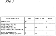
- Fig. 1 is a table illustrating an example of the image quality evaluation of a printed image based on the viewpoints of the droplet coating percentages on the printing medium and the visual sensitivity.
- the horizontal axis in Fig. 1 indicates the droplet coating percentages on the printing medium (%), and the vertical axis in Fig. 1 indicates the types of the unevenness and streaks appearing on the printed image ("granularity”, “white streak due to defective nozzle, white streak due to insufficient complementation”, and “black streak due to excessive complementation”).
- the droplet coating percentages on the printing medium are obtained by converting the gradations (pixel values) "0" to "255" of image data to percentages, "0%” corresponds to the pixel value "0", and "100%” corresponds to the pixel value "255".
- the "granularity" in the types of the unevenness and streaks represents the subjective "roughness” degree felt by a person when the image looks rough.
- the "white streak due to defective nozzle, white streak due to insufficient complementation” represents the white streak caused when a failure nozzle that does not discharge the ink is present, or the white streak caused due to the lacking of the amount of the ink complemented from a complementary nozzle.
- the "black streak due to excessive complementation” represents the black streak caused when the amount of the ink complemented from the complementary nozzle is excessive.
- the droplet coating percentage is less than 15%, the "granularity” is likely to be visually identified (the visual identification sensitivity " ⁇ ”).
- the "white streak due to defective nozzle, white streak due to insufficient complementation” is unlikely to be noticeable in this gradation, but is visually identified (the visual identification sensitivity " ⁇ ”).
- the “black streak due to excessive complementation” is likely to be visually identified in this gradation (the visual identification sensitivity " ⁇ ”). Therefore, in the case where the droplet coating percentage is less than 15%, it is desirable to perform the complementation so as to make the white streak unlikely to be noticeable without deteriorating the granularity and without performing the excessive complementation that causes the black streak.
- the droplet coating percentage is equal to or more than 15% and is less than 40%, the "granularity” is unlikely to be visually identified (the visual identification sensitivity " ⁇ "), but the "white streak due to defective nozzle, white streak due to insufficient complementation” is likely to be visually identified (the visual identification sensitivity " ⁇ "). On the other hand, the “black streak due to excessive complementation” is unlikely to be visually identified in this gradation (the visual identification sensitivity " ⁇ ").
- the cloth is less glossy than paper, and the ink dropped on the surface has low reflectance.
- the moisture absorptivity of the threads structuring the cloth is higher than that of the fibers structuring paper, and there is a gap between the threads structuring the cloth, so that the ink landed on the cloth is unlikely to be spread to its periphery as compared with the ink landed on the paper. From these reasons, when the printing medium P is the cloth, the black streak is not noticeable in the case where the droplet coating percentage is equal to or more than 15%. Therefore, it is desirable to perform the complementation so as to make the white streak unlikely to be noticeable without deteriorating the granularity in this gradation.
- the droplet coating percentage is equal to or more than 40%, the "granularity” and the “black streak due to excessive complementation” are unlikely to be visually identified (the visual identification sensitivity " ⁇ "), but the "white streak due to defective nozzle, white streak due to insufficient complementation” is likely to be visually identified (the visual identification sensitivity " ⁇ "). Therefore, since the black streak is not noticeable in this gradation even when the ink is excessively complemented, it is desirable to perform the complementation by a larger droplet for the purpose of complementing the white streak that is likely to be visually identified more emphasizingly.
- the selection of the size of the droplet used, the dot percentage (the dot filling percentage on the image data), and the balance of the droplet amount complemented are performed. More specifically, when the gradation of the recording data is low, the ink in the droplet amount equivalent to the conventional art is complemented, and when the gradation of the recording data is high, a droplet amount larger than the droplet amount that should have been discharged by the failure nozzle is discharged from the complementary nozzle.
- the respective nozzles adjacent to both sides of the failure nozzle are the complementary nozzles, and the complementation is performed by alternately switching each of the two complementary nozzles in each pixel row.
- the complementation is performed by alternately switching each of the two complementary nozzles in each pixel row.
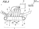
- FIG. 2 is an overall configuration diagram of an ink jet recording apparatus 1 according to an embodiment of the present invention. It should be noted that in Fig. 2 , the elements considered to be necessary for describing the present invention or the elements associated therewith are illustrated, and an image forming system of the present invention is not limited to the example illustrated in Fig. 2 .
- the ink jet recording apparatus 1 includes a conveying unit 2 and a recording unit 4. Further, the ink jet recording apparatus 1 includes an image reading unit 11, a belt cleaning unit 5, a belt drying unit 6, and a control unit 60.
- the conveying unit 2 includes a driving roller 21, a driven roller 22, an endless conveying belt 23, a pressing unit 24, and a separation roller 25.
- the endless conveying belt 23 is for example, a steel belt here.
- the conveying belt 23 is entrained between the driving roller 21 and the driven roller 22 to perform revolution operation (moving operation).
- the pressing unit 24 On the upper face of the conveying belt 23 and on the upstream side of the recording unit 4 in the conveying direction conveying the printing medium P, the pressing unit 24 is disposed.
- the pressing unit 24 is formed in a roller shape, and is rotatably supported by a supporting unit, not illustrated.
- the length in the axial direction of the pressing unit 24 is set to be longer than the length in the width direction of a belt member 3, and the pressing unit 24 is disposed so as to cover the conveying belt 23 from one end to the other end in the width direction of the conveying belt 23.
- the pressing unit 24 presses the printing medium P conveyed to the conveying unit 2 toward the outer peripheral face of the conveying belt 23.
- the separation roller 25 On the upper face of the conveying belt 23 and on the downstream side of the recording unit 4 in the conveying direction, the separation roller 25 is disposed.
- the separation roller 25 separates the printing medium P passed through the recording unit 4 from the conveying belt 23.
- the printing medium P is placed on the placing face, and is conveyed with the revolution movement of the conveying belt 23.
- the printing medium P and the conveying belt 23 are opposite the plane of the recording unit 4 in which the respective inks are discharged from the nozzles of respective head units 40Y, 40M, 40C, and 40K of the recording unit 4 (the ink discharging plane).
- the recording unit 4 has the head units 40Y, 40M, 40C, and 40K individually provided for respective colors of yellow (Y), magenta (M), cyan (C), and black (K).
- the head units 40Y, 40M, 40C, and 40K are disposed in the order of the head units 40Y, 40M, 40C, and 40K from the upstream side with respect to the conveying direction of the printing medium P.
- Each of the head units 40Y, 40M, 40C, and 40K is provided to have a length (width) covering the entire printing medium P for the direction perpendicular to the conveying direction of the printing medium P (the width direction of the printing medium P). And, each of the head units 40Y, 40M, 40C, and 40K forms an image by scanning at a time (in one direction) with respect to the recording surface of the printing medium P. That is, the ink jet recording apparatus 1 is an ink jet recording apparatus that adopts a one-pass method. In the following description, when the head units 40Y, 40M, 40C, and 40K are not required to be individually discriminated, these are collectively called a head unit 40.
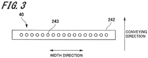
- Fig. 3 is a plan view illustrating a state where the head unit 40 is seen from the printing medium P side.
- the head unit 40 has a plurality of nozzles 243 disposed to be arrayed in a line along the width direction of the printing medium P.
- Each of the nozzles 243 is selectively operated by the control unit 60 based on the recording data, and discharges the ink in color corresponding to each of the head units 40Y, 40M, 40C, and 40K.
- the ink discharged from the nozzle 243 is landed on the surface of the printing medium P opposite the recording unit 4 (the recording surface).
- the inks in the respective colors of Y, M, C, and K are successively discharged from the respective head units 40Y, 40M, 40C, and 40K onto the printing medium P, so that the desired image is formed on the printing medium P.
- the recording data in four gradations are used, and driving waveforms corresponding to the respective gradation values are determined such that the droplet amounts of the inks discharged from the nozzles 243 are respectively 0 pL, 7 pL, 19 pL, and 30 pL according to the gradation values (0, 1, 2, 3) (the pixel values) of the respective pixels of the recording data.
- the inks used by the ink jet recording apparatus 1 of the present embodiment are for example, pigment inks.
- the image reading unit 11 is provided on the downstream side of the recording unit 4 in the conveying direction of the printing medium P, and as illustrated in Fig. 1 , reads the imaging surface of the printing medium P conveyed by the conveying belt 23.
- the image reading unit 11 has an illumination unit (not illustrated) emitting white light onto the printing medium P conveyed on the placing face of the conveying belt 34, and an imaging unit (not illustrated) detecting reflection light from the printing medium P.
- the illumination unit includes a plurality of white light sources including, for example, white color LEDs (Light Emitting Diodes).
- the imaging unit includes, for example, a CCD (Charge Coupled Device) sensor or a CMOS (Complementary Metal Oxide Semiconductor) sensor, and includes a line sensor having sensitivity to the light having the wavelength in the visible light region.
- the illumination unit emits the white light under the control of the control unit 60 when the image formed on the printing medium P passes immediately below the illumination unit. Then, the imaging unit images the reflection light reflected on the imaging surface.
- the image reading unit 11 can image a one-dimensional image of the image formed on the printing medium P (the image for one pixel row). The image reading unit 11 can obtain a two-dimensional image by repeating the imaging at intervals according to the conveying speed of the printing medium P.
- the belt cleaning unit 5 is disposed on the downstream side of the belt drying unit 6 in the conveying direction indicated by the leftward arrow in the drawing.
- the belt cleaning unit 5 has a nozzle that blows a cleaning solution onto the outer peripheral face of the conveying belt 23. And, the belt cleaning unit 5 blows the cleaning solution from the nozzle, and washes away the ink that adheres to the outer peripheral face of the conveying belt 23. It should be noted that the belt cleaning unit 5 does not necessarily have the nozzle blowing the cleaning solution, and for example, a cleaning roller that abuts on the outer peripheral face of the conveying belt 23 and is impregnated with the cleaning solution may be used, and other various cleaning mechanisms are applicable.
- the belt drying unit 6 dries the cleaning solution that is allowed to adhere to the conveying belt 23 by the belt cleaning unit 5.
- the belt drying unit 6 can adopt, for example, a configuration blowing air onto the conveying belt 23.
- the belt drying unit 6 may include a plate-shaped blade that scrapes off the cleaning solution that adheres to the conveying belt 23.
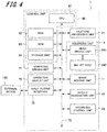
- Fig. 4 is a block diagram illustrating the configuration of the control system of the ink jet recording apparatus 1 according to the present embodiment.
- the ink jet recording apparatus 1 according to the present embodiment includes the control unit 60, an input-output interface 70, the recording unit 4, a conveying driving unit 71, an operation display unit 72, the image reading unit 11, a halftone processing unit 41, a nozzle designation unit 42, and a recording control unit 43.
- the control unit 60 has, for example, a CPU (Central Processing Unit) 61, a RAM (Random Access Memory) 62 used as the operation region of the CPU 61, and a ROM (Read Only Memory) 63 for storing a program and the like executed by the CPU 61. Further, the control unit 60 has a storage unit 64 including a hard disk drive and the like as a large capacity storage device. The storage unit 64 stores the data of the image read by the image reading unit 11, a test chart for detecting the discharge failure of the nozzle, information for performing the discharge failure examination operation of the nozzle, and the like.
- a CPU Central Processing Unit
- RAM Random Access Memory
- ROM Read Only Memory
- the CPU 61 of the control unit 60 is connected to each of the RAM 62, the ROM 63, the storage unit 64, the input-output interface 70, the recording unit 4, the conveying driving unit 71, the operation display unit 72, the image reading unit 11, the halftone processing unit 41, the nozzle designation unit 42, and the recording control unit 43 via a system bus B. And, the control unit 60 controls the operation of each of these units.
- control unit 60 Based on the reading image data of the test chart transmitted from the image reading unit 11, the control unit 60 detects the nozzle 243 in which the discharge failure is caused. Also, the control unit 60 image processes the image data received from the input-output interface 70. Further, the control unit 60 performs image processing, such as shading correction, image density adjustment, and image compression with respect to the received image data, if necessary.
- the conveying driving unit 71 driving controls the conveying unit 2 (see Fig. 2 ) under the control of the control unit 60.
- the operation display unit 72 is a touch panel including a liquid crystal display device (LCD) or an image display device, such as an organic LED.
- the operation display unit 72 displays an instruction menu with respect to the user, information related to the discharge detection operation of the nozzle, information related to the obtained image data, and the like.
- the operation display unit 72 includes a plurality of keys, and serves as an input unit receiving data inputs, such as various instructions, letters, and numbers by the key operation of the user.
- the input-output interface 70 is connected to an external device 100, such as a PC (personal computer) and a facsimile device. And, the input-output interface 70 outputs the image data received from the external device 100 to the control unit 60.
- an external device 100 such as a PC (personal computer) and a facsimile device.
- the image reading unit 11 emits the white light onto the printing medium P at a predetermined timing under the control of the control unit 60, and images the reflection light to read the image formed on the printing medium P. Then, the image reading unit 11 transmits the reading image data obtained by the reading to the control unit 60.
- the halftone processing unit 41 performs color conversion processing with respect to the image data, and performs halftone processing, such as dithering processing and error diffusion processing, thereby reducing the gradation number of each pixel of the image data to the gradation number that can be represented by the ink jet recording apparatus 1.
- the recording data that is the data obtained by the halftone processing is supplied to the recording unit 4.
- the halftone processing unit 41 subjects the data of the image data (for example, 256 gradations) to the halftone processing to generate the recording data including four gradations of "0", “1", “2", and "3".
- the pixel value "1" of the recording data is represented as a "small droplet”
- the pixel value "2” is represented as the “small droplet” and a “medium droplet”
- the pixel value "3" is represented as a "large droplet”.
- the halftone processing unit 41 performs the control of the droplet size and the dot percentage (the dot filling percentage on the recording data) according to the magnitude of the pixel value of the image data (the magnitude of the droplet coating percentage).
- the control processing of the droplet size and the dot percentage by the halftone processing unit 41 will be described in detail with reference to Figs. 5 and 6 illustrated later.
- the color conversion processing and the halftone processing performed by the halftone processing unit 41 may be performed by the control unit 60, an image processing unit, not illustrated, and the like of the ink jet recording apparatus 1.
- the gradation numbers of the image data and the gradation numbers of the recording data are examples, and the present invention is not limited to these.
- the recording unit 4 receives the recording data generated by the halftone processing unit 41, and forms a predetermined image on the printing medium P based on the recording data. Specifically, by driving each head driving unit 241 of the respective head units 40Y, 40M, 40C, and 40K configuring the recording unit 4, the ink is discharged from each of ink jet heads 242 to a predetermined position on the printing medium P.
- the nozzle designation unit 42 designates the discharge failure nozzle 243 detected by the control unit 60 as the "failure nozzle", and sets the nozzle disposed at a second position adjacent to a first position that is the disposing position of the failure nozzle in the width direction of the printing medium P (for example, adjacent to the right side of the first position toward the conveying direction) to a first complementary nozzle. Further, the nozzle designation unit 42 sets the nozzle disposed at a third position adjacent to the first position and other than the second position (for example, adjacent to the left side of the first position toward the conveying direction) to a second complementary nozzle.
- the recording control unit 43 edits the recording data such that when the failure nozzle is designated, the ink is not discharged from the failure nozzle. Also, the recording control unit 43 calculates a complementary value allocated with respect to the first complementary nozzle or the second complementary nozzle designated by the nozzle designation unit 42, and allocates the complementary value to the first complementary nozzle or the second complementary nozzle. The detail of droplet complementation processing by the recording control unit 43 will be described later.
- Fig. 5 is a graph illustrating the control example of the dot percentage by the halftone processing unit 41.
- the small droplet is indicated by a solid line
- the medium droplet is indicated by a dashed line
- the large droplet is indicated by an alternate long and short dashes line.
- Fig. 6 is a graph illustrating the control example of the droplet size by the halftone processing unit 41.
- the vertical axis in Fig. 6 indicates the dot percentage
- the horizontal axis indicates the droplet coating percentage (%).
- the control of the droplet size and the dot percentage by the halftone processing unit 41 will be described by three cases of the case where the droplet coating percentage is less than 15% (an example of a first threshold value), the case where the droplet coating percentage is equal to or more than 15% and is less than 40% (an example of a second threshold value), and the case where the droplet coating percentage is equal to or more than 40%.
- the halftone processing unit 41 performs the image printing only by the pixel value "1" (the small droplet).
- the granularity the roughness of the image
- the minimum droplet the small droplet
- the halftone processing unit 41 performs the control that reduces the dot percentage up to 40%.
- the image printing is performed only by the pixel value "1" (the small droplet), as described above. Since the small droplet has a small droplet diameter, the ink landed on the printing medium P is not spread to the extent that the droplet that becomes defective because the adjacent nozzle cannot discharge the ink can be complemented.
- the control to the dot percentage an upper limit of 40%
- the dot percentage exceeds 50%, the number of dots continuously disposed in the nozzle row direction is increased, and the adjacent dot is likely to be image printed, so that the halftone processing unit 41 performs the control that reduces the dot percentage up to 40%.
- the halftone processing unit 41 performs the image printing by using the pixel value "1" (the small droplet) and the pixel value "2" (the medium droplet).
- the density of the ink is made higher by replacing the dot of the small droplet with the dot of the medium droplet.
- the halftone processing unit 41 performs the control that reduces the dot percentage up to 40%.
- the white streak is more noticeable than the black streak also in this gradation, thereby performing the control to make the white streak unlikely to be noticeable by providing the gap between the droplets landed on the printing medium P to some extent (the control that reduces the dot percentage up to 40%).
- the halftone processing unit 41 performs the image printing by using the pixel value "2" (the medium droplet) and the pixel value "3" (the large droplet).
- the halftone processing unit 41 performs the image printing only by using the pixel value "2" (the medium droplet) and the pixel value "3" (the large droplet) without using the pixel value "1" (the small droplet).
- the halftone processing unit 41 performs the control that reduces the dot percentage up to 60%.
- the black streak is unlikely to be visually identified while the white streak is likely to be visually identified. Therefore, by performing the complementation by the droplet that is as large as possible, the white streak can be made unlikely to be noticeable more efficiently.
- the ink jet recording apparatus 1 according to the present embodiment adopts the one-pass method, when the ink in the largest amount that can be discharged by the nozzle during the image printing is discharged, the complementation cannot be performed.
- the halftone processing unit 41 provides a margin with respect to the largest density by reducing the dot percentage up to 60% to allow approximately 1/3 (33%) of the image printing surface to have blank dots.
- the ink jet recording apparatus 1 that adopts the one-pass method can also perform the complementation using the large droplet, so that in the case where the droplet coating percentage is equal to or more than 40% of the largest ink amount, the white streak can be made unlikely to be noticeable.
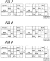
- Fig. 7 is a diagram illustrating an example of effective complementation in the case where the droplet coating percentage is less than 15%
- Fig. 8 is a diagram illustrating an example of effective complementation in the case where the droplet coating percentage is approximately 20%.
- Fig. 9 is a diagram illustrating an example of effective complementation in the case where the droplet coating percentage is approximately 30%
- Fig. 10 is a diagram illustrating an example of effective complementation in the case where the droplet coating percentage is approximately 60%.
- Fig. 11 is a diagram illustrating an example of effective complementation in the case where the droplet coating percentage is 100%.
- the left drawing is a diagram illustrating the droplet amount corresponding to the pixel value of each pixel included in the range of three pixel rows by five pixel columns of the recording data before the complementation
- the right drawing is a diagram illustrating the droplet value corresponding to the pixel value of each pixel included in the range of the recording data after the complementation.
- the nozzle that performs the image printing of the pixel in the second column from the right in the drawing is the failure nozzle (represented as "defective" in the drawing).
- the nozzle adjacent to the right side of the failure nozzle (the left side in the drawing) toward the conveying direction indicated by the downward arrow in the drawing is allocated to the complementary nozzle.
- the droplet coating percentage is less than 15%, as illustrated in the drawing on the left side in Fig. 7 , the image printing is performed only by the small droplets, and the distance between the droplets is large. Thus, when the white streak is caused since any one of the nozzles is the failure nozzle, the white streak is unlikely to be noticeable. Also, in this gradation, as illustrated in Fig. 1 , the granularity and the black streak due to excessive complementation are more noticeable. Therefore, in this gradation, the complementation using the small droplet is effective.
- the medium droplet percentage is low, so that as illustrated in the right drawing in Fig. 8 , the black streak is not noticeable when the complementation is performed by the large droplet. Also, in the case where the droplet coating percentage is approximately 30%, as illustrated in the left drawing in Fig. 9 , the medium droplet percentage is high, the black streak is unlikely to be visually identified. On the other hand, since the white streak becomes noticeable, as illustrated in the right drawing in Fig. 9 , the large droplet having a large droplet diameter is more suitable for the complementation. Therefore, it is effective to perform the defective complementation by the medium droplet used often in these gradations by using the large droplet.
- the image printing is performed only by the medium droplets, so that the black streak is not visually identified, and the visibility of the white streak is increased.
- the image printing is performed by the medium droplets and the large droplets, so that the black streak is not visually identified, and the visibility of the white streak is increased. Therefore, when the droplet that should have been discharged by the failure nozzle is the large droplet, the complementation using the large droplet is effective.
- the recording control unit 43 sets the small pixel value also to the complementary value added to the pixel value to be discharged from the complementary nozzle adjacent to the failure nozzle.
- the defective pixel value is at the medium level or more, the large pixel value is set to the complementary value.
- Fig. 12 is a table illustrating the correspondence of each pixel value of the recording data and each complementary value.
- the recording control unit 43 sets the complementary value to "0 (null)”.
- the recording control unit 43 sets the complementary value to "1" (7 pL).
- the recording control unit 43 sets the complementary value to "3" (30 pL).
- the recording control unit 43 also sets the complementary value to "3" (30 pL).
- the correspondence relation between each pixel value of the recording data and each complementary value that is added to the droplet amount discharged by the complementary nozzle is stored in, for example, a register (2 bit register), not illustrated, and the like of the storage unit 64 (see Fig. 4 ).
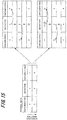
- FIG. 13 is a diagram illustrating an example of the processing for allocating each complementary value to each complementary nozzle by the recording control unit 43.
- Fig. 13 is a diagram illustrating an example of the complementation of the ink based on the recording data after correction.
- the left drawing in Fig. 13 is a diagram illustrating the amount of the ink to be discharged corresponding to each pixel included in the range of pixel rows R1 to R13 and pixel columns C1 to C3 of the recording data before correction by the size and the pattern of a circular mark.
- the right drawing in Fig. 13 is a diagram illustrating the amount of the ink discharged corresponding to each pixel in the range of the recording data after correction by the size and the pattern of a circular mark.
- Each of the pixel columns C1 to C3 in Fig. 13 corresponds to any one of three nozzles 243 adjacent to each other, and the ink corresponding to the pixel included in one pixel column is discharged from the same corresponding nozzle 243. Also, the pixel rows R1 to R13 respectively include the pixels corresponding to the three nozzles 243.
- the pixel value "0" is indicated by a blank section
- the small droplet corresponding to the pixel value "1" (7 pL) is indicated by the circular mark having a small diameter in a fine dot pattern.
- the medium droplet (19 pL) corresponding to the pixel value "2” is indicated by the circular mark having a medium-sized diameter in a diagonal line pattern
- the large droplet (30 pL) corresponding to the pixel value "3" is indicated by the circular mark having a large diameter in a rough dot pattern.
- the defective pixel that should have been discharged from the failure nozzle is indicated by the white circular mark.
- the nozzle 243 corresponding to the pixel column C2 is designated as the failure nozzle (represented as “defective” in the drawing). Also, it is assumed that the nozzle adjacent to the left side of the failure nozzle in the drawing is set to the first complementary nozzle (represented as “complementation 1" in the drawing), and the nozzle adjacent to the right side of the failure nozzle in the drawing is set to the second complementary nozzle (represented as “complementation 2" in the drawing).
- the pixel value corresponding to the droplet amount that should have been discharged by the failure nozzle is "0", so that the complementary value is also set to "0". That is, the droplet complementation by the recording control unit 43 is not performed.
- the defective pixel value is "1" (the small droplet), so that the pixel value "1” (the small droplet) is set to the complementary value.
- the complementation in the pixel row R2 is performed from the first complementary nozzle.
- the pixel value to be discharged from the first complementary nozzle is "0", so that the droplet amount after the complementation is also the small droplet.
- the defective pixel value is "1" (the small droplet), so that the pixel value "1” (the small droplet) is set to the complementary value.
- the complementation in the pixel row R3 is performed from the second complementary nozzle.
- the pixel value to be discharged from the second complementary nozzle is "1" (the small droplet), the droplet amount after the complementation is the pixel value "2" (the medium droplet) obtained by adding the pixel value "1" that is the complementary value to the pixel value "1".
- the defective pixel value is "1" (the small droplet), so that the pixel value "1” (the small droplet) is set to the complementary value.
- the complementation in the pixel row R4 is performed from the first complementary nozzle.
- the pixel value to be discharged from the first complementary nozzle is "2" (the medium droplet), so that the droplet amount after the complementation is the pixel value "3" (the large droplet) obtained by adding the pixel value "1" that is the complementary value to the pixel value "2".
- the defective pixel value is "1" (the small droplet), so that" 1" (the small droplet) is set to the complementary value.
- the complementation in the pixel row R5 is to be performed from the second complementary nozzle, but the pixel value to be discharged from the second complementary nozzle (an example of a fourth pixel value) is "3" (the large droplet).
- "3" (the large droplet) is the pixel value corresponding to the largest droplet amount that can be discharged by the second complementary nozzle (the largest pixel value), so that the addition of the complementary value to the second complementary nozzle cannot be performed. In such a case, the complementary value in the portion that cannot be added is discarded.
- the defective pixel value is "2" (the medium droplet), so that the pixel value "3" (the large droplet) (an example of a second pixel value) is set to the complementary value.
- the complementation in the pixel row R6 is performed from the first complementary nozzle.
- the pixel value to be discharged from the first complementary nozzle is "0", so that the droplet amount after the complementation is the pixel value "3" (the large droplet) obtained by adding the complementary value "3" to the pixel value "0".
- the defective pixel value is "2" (the medium droplet), so that the pixel value "3" (the large droplet) is set to the complementary value.
- the complementation in the pixel row R7 is performed from the second complementary nozzle.
- the pixel value to be discharged from the second complementary nozzle is "2" (the medium droplet), so that the droplet amount after the complementation is the large droplet.
- the pixel value "3" (the large droplet) set to the complementary value is added to the pixel value corresponding to the droplet discharged by the second complementary nozzle, the pixel value after the addition (called a post-addition pixel value) exceeds the largest pixel value corresponding to the largest droplet amount that can be discharged by the second complementary nozzle. That is, the complementary value cannot be allocated to the second complementary nozzle. Therefore, the pixel value "1" in the portion that cannot be allocated (difference) is allocated to the first complementary nozzle.
- the pixel value to be discharged from the first complementary nozzle is "1" (the small droplet), so that the droplet amount after the complementation is the medium droplet corresponding to the post-addition pixel value "2" obtained by adding the pixel value "1" that is the difference to the pixel value "1".
- the defective pixel value is "3" (the large droplet), so that the pixel value "3" (the large droplet) is set to the complementary value.
- the complementation in the pixel row R10 is performed from the first complementary nozzle.
- the pixel value to be discharged from the first complementary nozzle is "0". Therefore, the droplet amount after the complementation by the first complementary nozzle is the pixel value "3" (the large droplet) obtained by adding the complementary value "3" to the pixel value "0".
- the recording control unit 43 sets the second pixel value (for example, the pixel value "3") larger than the first pixel value (for example, the pixel value "2") corresponding to the droplet amount that should have been discharged by the failure nozzle to the complementary value, adds the complementary value to the third pixel value corresponding to the droplet amount that should have been discharged by the complementary nozzle, and discharges the ink in the droplet amount corresponding to the post-addition pixel value obtained by the addition from the complementary nozzle. Therefore, according to the present embodiment, in the ink jet recording apparatus 1, by increasing the ink amount discharged from the complementary nozzle, the white streak caused because the ink is unlikely to be spread on the surface of the printing medium P can be made unlikely to be noticeable.
- the ink in one complementation operation performed with respect to one pixel row, the ink is not discharged from the two nozzles of the first complementary nozzle and the second complementary nozzle adjacent to the failure nozzle at the same time, but is discharged from one of the complementary nozzles. That is, at the rate lower than the case where the ink is discharged from both of the two nozzles, the dot in the larger droplet amount is dotted on the printing medium P. Therefore, according to the present embodiment, from the viewpoint of the characteristic of the ink in which the ink is unlikely to be spread on the surface of the cloth as the printing medium P, a large number of dots in the large droplet amount are dotted, so that the improving effect with respect to the white streak can be further improved.
- the pixel value of the recording data and the complementary value are previously managed so as to correspond to each other. Therefore, by the simple complementation processing in which the complementary value is alternately allocated with respect to the first complementary nozzle or the second complementary nozzle, the white streak in the high gradation portion in which the droplet coating percentage is high can be made unlikely to be visually identified.
- the respective nozzles adjacent to both sides of the failure nozzle are the first complementary nozzle and the second complementary nozzle, and the recording control unit 43 performs the complementation while alternately using each of the first complementary nozzle and the second complementary nozzle. Therefore, according to the present embodiment, the spreads of the droplets landed on the printing medium P (cloth) can be connected in the diagonal direction, so that in particular, the complementation effect of the white streak can be improved.
- each of the pixel value of the recording data and the complementary value is managed by the one-digit value, so that these information can be stored in the 2 bit register and the like. Therefore, according to the present embodiment, the number of registers can be reduced, and the cost of the ink jet recording apparatus 1 can be reduced.
- each of the pixel value of the recording data and the complementary value is managed by the one-digit value, and the processing for alternately allocating the complementary value to each of the first complementary nozzle and the second complementary nozzle can also be easily performed. Therefore, in the present embodiment, the complementation processing can be implemented on the hardware, and the complementation processing can be executed at higher speed.
- the recording control unit 43 allocates (adds) the complementary value to each of the first complementary nozzle and the second complementary nozzle in each pixel row is given, but the present invention is not limited to this.
- the recording control unit 43 may allocate the complementary value to, of the first complementary nozzle and the second complementary nozzle, the complementary nozzle in which the pixel value corresponding to the droplet amount that should have been discharged is smaller.
- Fig. 14 is a diagram illustrating an example of processing for allocating the complementary value to the complementary nozzle by the recording control unit 43 according to a first modification.
- the pixel value that should have been discharged by the failure nozzle is "3".
- the pixel value that should have been discharged by the first complementary nozzle indicated as “complementation 1" (represented as “complementation 1” in the drawing) is "0”
- the pixel value that should have been discharged by the second complementary nozzle represented as “complementation 2" in the drawing) is "2”.
- the recording control unit 43 performs the allocation of the complementary value with respect to the first complementary nozzle in which the pixel value that should have been discharged is "0".
- the recording control unit 43 can perform the complementation using only one of the complementary nozzles without performing the complementation using both of the first complementary nozzle and the second complementary nozzle.
- Fig. 15 is a diagram illustrating an example of the processing for allocating each complementary value to each complementary nozzle by the recording control unit 43 according to the second modification.
- the left drawing in Fig. 15 illustrates an example of two pixel rows continuous in the conveying direction of the recording data before the correction.
- the upper drawing on the right side is a diagram illustrating a state where the pixel value "3" corresponding to the droplet amount that should have been discharged by the failure nozzle is allocated to both of the second complementary nozzle and the first complementary nozzle.
- the recording control unit 43 first allocates the pixel value "3" corresponding to the droplet amount that should have been discharged by the failure nozzle, to the second complementary nozzle, but since the pixel value corresponding to the droplet amount that should have been discharged by the second complementary nozzle is "2", the pixel value that can perform the allocation (addition) is only "1".
- the recording control unit 43 allocates the pixel value "2" in the portion that cannot be allocated to the second complementary nozzle, to the first complementary nozzle.
- the pixel value corresponding to the droplet amount that should have been discharged by the first complementary nozzle is "3”
- the pixel value "3" is the pixel value corresponding to the largest droplet amount that can be discharged by the complementary nozzle. Therefore, the allocation of the pixel value to the first complementary nozzle cannot be performed.
- the recording control unit 43 temporarily holds the pixel value "2" in the portion that cannot be allocated, and performs the allocation of the pixel value in the unallocated portion in the latter-stage pixel row in the conveying direction.
- the lower drawing on the right side in Fig. 15 illustrates an example of the processing for allocating the pixel value in the unallocated portion by the recording control unit 43.
- the pixel value corresponding to the droplet amount that should have been discharged by the failure nozzle is "3" (see the left drawing in Fig. 15 ).
- the recording control unit 43 allocates the pixel value "5" obtained by adding the pixel value "2" that cannot be allocated in the previous-stage pixel row to this "3", to the second complementary nozzle and the first complementary nozzle. Since the pixel value corresponding to the droplet amount that should have been discharged by the second complementary nozzle is "0", the recording control unit 43 allocates "3" of the pixel value "5" to the second complementary nozzle.
- the recording control unit 43 allocates the remaining pixel value "2" after the pixel value "3" is allocated, to the first complementary nozzle. Since the pixel value corresponding to the droplet amount that should have been discharged by the first complementary nozzle is "0", the recording control unit 43 allocates the pixel value "2" to the first complementary nozzle.
- the recording control unit 43 can allocate the ink to the first complementary nozzle and the second complementary nozzle without discarding the ink.
- the magnitude of the pixel value temporarily held is desirably up to "3" (up to the next pixel row).
- the recording control unit 43 may select one of the first complementary nozzle and the second complementary nozzle according to the contents of various disturbances causing the tilting of the ink jet head 242 of the recording unit 4 or the displacement of the landing position of the ink discharged from the nozzle 243 onto the printing medium.
Landscapes
- Engineering & Computer Science (AREA)
- Quality & Reliability (AREA)
- Ink Jet (AREA)
- Particle Formation And Scattering Control In Inkjet Printers (AREA)
Abstract
Description
- The entire disclosure of Japanese Patent Application No.
2018-158978, filed on Aug.28, 2018 - The present invention relates to an ink jet recording apparatus.
- Conventionally, an ink jet recording apparatus that discharges (ejects) ink droplets from a plurality of nozzles while relatively moving a recording head having the plurality of nozzles and a printing medium and lands the ink droplets on the printing medium, such as a sheet, to form an image has been known.
- In the ink jet recording apparatus, when the discharge failure of the ink from the recording head is caused, a region in which the ink is not landed on the printing medium occurs. And, the region in which the ink is not landed is identified as a so-called white streak. The discharge failure of the ink includes, for example, non-discharge in which the ink is not discharged from the nozzle of the recording head, weak discharge in which discharge is weak, bending discharge in which discharge is bended, and the like.
- Since the printing medium on which the white streak is caused becomes a defective product, a technology for complementing the white streak has been conventionally contrived. The complementation of the white streak is performed by, for example, editing image data. Specifically, the complementation of the white streak is performed by, for example, recording the droplet amount of the ink that should have been discharged from the failure (defective) nozzle in which the discharge failure is caused, and allocating the ink in the amount equal to the droplet amount to the nozzle adjacent to the defective nozzle or the nozzle around the defective nozzle.
- For example, Patent Literature 1 (Japanese Unexamined Patent Application Publication No.
2015-136883 - Patent Literature 1: Japanese Unexamined Patent Application Publication No.
2015-136883 - In the recent ink jet recording apparatus, there are various printing media on which an image is formed, and the ink jet recording apparatus sometimes forms an image on the printing medium, such as a cloth, other than paper. However, when the printing medium is, for example, the cloth, the ink landed on the cloth is unlikely to be spread on the surface of the cloth. This is because such unlikeliness of ink spreading is affected by moisture absorptivity that the fibers themselves structuring the cloth have, and the weaving structure and the like of the cloth.
- Therefore, in the case of performing printing with respect to the printing media made of various materials, like the technology described in
Patent Literature 1, when the droplet amount of the ink that should have been discharged from the defective nozzle is simply allocated to the nozzle adjacent to the defective nozzle and the nozzle around the defective nozzle, the complementation cannot be completely performed since the spreading amount of the ink is small, with the result that the white streak is sometimes caused. - The present invention has been made in view of such circumstances, and an object of the present invention is to perform, in an ink jet recording apparatus, complementation that makes a white streak unlikely to be visually identified.
- To solve the abovementioned problems, according to an aspect of the present invention, an ink jet recording apparatus reflecting one aspect of the present invention comprises, for example, a recording unit having a plurality of nozzles disposed in a first direction and each capable of discharging ink in the droplet amount corresponding to the magnitude of each pixel value of recording data obtained by subjecting image data to halftone processing, a conveying unit relatively moving the recording unit and a printing medium in a second direction orthogonal to the first direction, a control unit selectively operating the plurality of nozzles based on the recording data to form an image on the printing medium, a nozzle designation unit designating, of the plurality of nozzles, the nozzle that does not normally discharge the ink as a failure nozzle and setting the nozzle disposed at a second position adjacent to a first position that is the disposing position of the failure nozzle in the first direction to a complementary nozzle complementing the ink that should have been discharged by the failure nozzle, and a recording control unit editing the image data such that the ink is not discharged from the failure nozzle, setting a second pixel value larger than a first pixel value corresponding to the droplet amount of the ink that should have been discharged by the failure nozzle to a complementary value, adding the complementary value to a third pixel value corresponding to the droplet amount of the ink that should have been discharged by the complementary nozzle, and discharging the ink in the droplet amount corresponding to a post-addition pixel value obtained by the addition from the complementary nozzle.
- It should be noted that objects, configurations, and effects other than the above will be apparent from the description of the following embodiment.
- The advantages and features provided by an embodiment of the invention will become more fully understood from the detailed description given hereinbelow and the appended drawings which are given by way of illustration only, and thus are not intended as a definition of the limits of the present invention:
-
Fig. 1 is a table illustrating an example of the image quality evaluation of a printed image based on the viewpoints of droplet coating percentages on a printing medium and visual sensitivity (visibility); -
Fig. 2 is an overall configuration diagram of an ink jet recording apparatus according to an embodiment of the present invention; -
Fig. 3 is a plan view illustrating a state where a head unit is seen from the printing medium side according to an embodiment of the present invention; -
Fig. 4 is a block diagram illustrating the configuration of the control system of the ink jet recording apparatus according to an embodiment of the present invention; -
Fig. 5 is a graph illustrating the control example of dot percentage by a halftone processing unit according to an embodiment of the present invention; -
Fig. 6 is a graph illustrating the control example of droplet size by the halftone processing unit according to an embodiment of the present invention; -
Fig. 7 is a diagram illustrating an example of effective complementation in the case where the droplet coating percentage is less than 15% according to an embodiment of the present invention; -
Fig. 8 is a diagram illustrating an example of effective complementation in the case where the droplet coating percentage is approximately 20% according to an embodiment of the present invention; -
Fig. 9 is a diagram illustrating an example of effective complementation in the case where the droplet coating percentage is approximately 30% according to an embodiment of the present invention; -
Fig. 10 is a diagram illustrating an example of effective complementation in the case where the droplet coating percentage is approximately 60% according to an embodiment of the present invention; -
Fig. 11 is a diagram illustrating an example of effective complementation in the case where the droplet coating percentage is 100% according to an embodiment of the present invention; -
Fig. 12 is a table illustrating the correspondence of each pixel value of recording data and each complementary value according to an embodiment of the present invention; -
Fig. 13 is a diagram illustrating an example of processing for allocating each complementary value to each complementary nozzle by a recording control unit according to an embodiment of the present invention; -
Fig. 14 is a diagram illustrating an example of processing for allocating the complementary value to the complementary nozzle by the recording control unit according to a first modification; and -
Fig. 15 is a diagram illustrating an example of processing for allocating each complementary value to each complementary nozzle by the recording control unit according to a second modification. - Hereinafter, an embodiment of the present invention will be described with reference to the accompanying drawings. However, the scope of the invention is not limited to the disclosed embodiment. The components having substantially the same functions or configurations in this specification and the drawings are indicated by similar reference signs, and the overlapped description of the components is omitted.
- First, before the configuration examples of the embodiment is described, the above problems solved by the present invention will be described more specifically. When a printing medium is a cloth, the droplet amount of ink necessary for wetting and spreading on the printing medium of the ink landed on the printing medium becomes larger as compared with the case where the printing medium is paper. The moisture absorptivity of the threads structuring the cloth is higher than that of the fibers structuring the paper, and there is a gap between the threads structuring the cloth, so that the ink landed on the cloth is unlikely to be spread to its periphery as compared with the ink landed on the paper. Therefore, when the printing medium is the cloth, the types of streaks, unevenness, and the like that significantly appear are also changed according to the coating percentage of the ink on the printing medium.
- Here, referring to
Fig. 1 , the relation between the droplet coating percentages of the ink on the printing medium and the visual sensitivity (visibility) of the streaks, unevenness, and the like will be described.Fig. 1 is a table illustrating an example of the image quality evaluation of a printed image based on the viewpoints of the droplet coating percentages on the printing medium and the visual sensitivity. - The horizontal axis in
Fig. 1 indicates the droplet coating percentages on the printing medium (%), and the vertical axis inFig. 1 indicates the types of the unevenness and streaks appearing on the printed image ("granularity", "white streak due to defective nozzle, white streak due to insufficient complementation", and "black streak due to excessive complementation"). - The droplet coating percentages on the printing medium (%) are obtained by converting the gradations (pixel values) "0" to "255" of image data to percentages, "0%" corresponds to the pixel value "0", and "100%" corresponds to the pixel value "255".
- The "granularity" in the types of the unevenness and streaks represents the subjective "roughness" degree felt by a person when the image looks rough. The "white streak due to defective nozzle, white streak due to insufficient complementation" represents the white streak caused when a failure nozzle that does not discharge the ink is present, or the white streak caused due to the lacking of the amount of the ink complemented from a complementary nozzle. The "black streak due to excessive complementation" represents the black streak caused when the amount of the ink complemented from the complementary nozzle is excessive.
- The case where the droplet coating percentage is less than 15%
- In the case where the droplet coating percentage is less than 15%, the "granularity" is likely to be visually identified (the visual identification sensitivity "○"). The "white streak due to defective nozzle, white streak due to insufficient complementation" is unlikely to be noticeable in this gradation, but is visually identified (the visual identification sensitivity "Δ"). The "black streak due to excessive complementation" is likely to be visually identified in this gradation (the visual identification sensitivity "○"). Therefore, in the case where the droplet coating percentage is less than 15%, it is desirable to perform the complementation so as to make the white streak unlikely to be noticeable without deteriorating the granularity and without performing the excessive complementation that causes the black streak.
- The case where the droplet coating percentage is equal to or more than 15% and is less than 40%
- In the case where the droplet coating percentage is equal to or more than 15% and is less than 40%, the "granularity" is unlikely to be visually identified (the visual identification sensitivity "Δ"), but the "white streak due to defective nozzle, white streak due to insufficient complementation" is likely to be visually identified (the visual identification sensitivity "○"). On the other hand, the "black streak due to excessive complementation" is unlikely to be visually identified in this gradation (the visual identification sensitivity " × "). When a printing medium P is a cloth, the cloth is less glossy than paper, and the ink dropped on the surface has low reflectance. Also, the moisture absorptivity of the threads structuring the cloth is higher than that of the fibers structuring paper, and there is a gap between the threads structuring the cloth, so that the ink landed on the cloth is unlikely to be spread to its periphery as compared with the ink landed on the paper. From these reasons, when the printing medium P is the cloth, the black streak is not noticeable in the case where the droplet coating percentage is equal to or more than 15%. Therefore, it is desirable to perform the complementation so as to make the white streak unlikely to be noticeable without deteriorating the granularity in this gradation.
- The case where the droplet coating percentage is equal to or more than 40%
- In the case where the droplet coating percentage is equal to or more than 40%, the "granularity" and the "black streak due to excessive complementation" are unlikely to be visually identified (the visual identification sensitivity "×"), but the "white streak due to defective nozzle, white streak due to insufficient complementation" is likely to be visually identified (the visual identification sensitivity "○"). Therefore, since the black streak is not noticeable in this gradation even when the ink is excessively complemented, it is desirable to perform the complementation by a larger droplet for the purpose of complementing the white streak that is likely to be visually identified more emphasizingly.
- To solve the above problems, in the present embodiment, in each gradation of recording data, the selection of the size of the droplet used, the dot percentage (the dot filling percentage on the image data), and the balance of the droplet amount complemented are performed. More specifically, when the gradation of the recording data is low, the ink in the droplet amount equivalent to the conventional art is complemented, and when the gradation of the recording data is high, a droplet amount larger than the droplet amount that should have been discharged by the failure nozzle is discharged from the complementary nozzle.
- Also, in the present embodiment, the respective nozzles adjacent to both sides of the failure nozzle are the complementary nozzles, and the complementation is performed by alternately switching each of the two complementary nozzles in each pixel row. This is because by alternately discharging the ink from each of the two complementary nozzles along the conveying direction of the printing medium P, the spreads of the droplets landed on the printing medium P are connected in the diagonal direction, so that the complementation effect can be further improved. In particular, in the low gradation, by performing such control, the white streak can be made unlikely to be noticeable without deteriorating the granularity and without causing the black streak.
- The overall configuration of an ink jet recording apparatus
- Next, referring to
Fig. 2 , the configuration example of the ink jet recording apparatus according to an embodiment of the present invention will be described.Fig. 2 is an overall configuration diagram of an inkjet recording apparatus 1 according to an embodiment of the present invention. It should be noted that inFig. 2 , the elements considered to be necessary for describing the present invention or the elements associated therewith are illustrated, and an image forming system of the present invention is not limited to the example illustrated inFig. 2 . - As illustrated in
Fig. 2 , the inkjet recording apparatus 1 includes a conveyingunit 2 and arecording unit 4. Further, the inkjet recording apparatus 1 includes animage reading unit 11, abelt cleaning unit 5, abelt drying unit 6, and acontrol unit 60. - The conveying
unit 2 includes a drivingroller 21, a drivenroller 22, an endless conveyingbelt 23, apressing unit 24, and aseparation roller 25. - The endless conveying
belt 23 is for example, a steel belt here. The conveyingbelt 23 is entrained between the drivingroller 21 and the drivenroller 22 to perform revolution operation (moving operation). - On the upper face of the conveying
belt 23 and on the upstream side of therecording unit 4 in the conveying direction conveying the printing medium P, thepressing unit 24 is disposed. Thepressing unit 24 is formed in a roller shape, and is rotatably supported by a supporting unit, not illustrated. - The length in the axial direction of the
pressing unit 24 is set to be longer than the length in the width direction of abelt member 3, and thepressing unit 24 is disposed so as to cover the conveyingbelt 23 from one end to the other end in the width direction of the conveyingbelt 23. Thepressing unit 24 presses the printing medium P conveyed to the conveyingunit 2 toward the outer peripheral face of the conveyingbelt 23. - On the upper face of the conveying
belt 23 and on the downstream side of therecording unit 4 in the conveying direction, theseparation roller 25 is disposed. Theseparation roller 25 separates the printing medium P passed through therecording unit 4 from the conveyingbelt 23. - In the section in which the conveying
belt 23 moves horizontally such that the face on the outer peripheral side of the conveying belt 23 (the face on which the printing medium P is placed) faces upside, the printing medium P is placed on the placing face, and is conveyed with the revolution movement of the conveyingbelt 23. In this section, the printing medium P and the conveyingbelt 23 are opposite the plane of therecording unit 4 in which the respective inks are discharged from the nozzles ofrespective head units - The
recording unit 4 has thehead units head units head units - Each of the
head units head units jet recording apparatus 1 is an ink jet recording apparatus that adopts a one-pass method. In the following description, when thehead units head unit 40. - Here, referring to
Fig. 3 , the configuration example of thehead unit 40 will be described.Fig. 3 is a plan view illustrating a state where thehead unit 40 is seen from the printing medium P side. As illustrated inFig. 3 , thehead unit 40 has a plurality ofnozzles 243 disposed to be arrayed in a line along the width direction of the printing medium P. Each of thenozzles 243 is selectively operated by thecontrol unit 60 based on the recording data, and discharges the ink in color corresponding to each of thehead units nozzle 243 is landed on the surface of the printing medium P opposite the recording unit 4 (the recording surface). - In the present embodiment, the inks in the respective colors of Y, M, C, and K are successively discharged from the
respective head units nozzles 243 are respectively 0 pL, 7 pL, 19 pL, and 30 pL according to the gradation values (0, 1, 2, 3) (the pixel values) of the respective pixels of the recording data. - The inks used by the ink
jet recording apparatus 1 of the present embodiment are for example, pigment inks. - The
image reading unit 11 is provided on the downstream side of therecording unit 4 in the conveying direction of the printing medium P, and as illustrated inFig. 1 , reads the imaging surface of the printing medium P conveyed by the conveyingbelt 23. - The
image reading unit 11 has an illumination unit (not illustrated) emitting white light onto the printing medium P conveyed on the placing face of the conveying belt 34, and an imaging unit (not illustrated) detecting reflection light from the printing medium P. The illumination unit includes a plurality of white light sources including, for example, white color LEDs (Light Emitting Diodes). The imaging unit includes, for example, a CCD (Charge Coupled Device) sensor or a CMOS (Complementary Metal Oxide Semiconductor) sensor, and includes a line sensor having sensitivity to the light having the wavelength in the visible light region. - The illumination unit emits the white light under the control of the
control unit 60 when the image formed on the printing medium P passes immediately below the illumination unit. Then, the imaging unit images the reflection light reflected on the imaging surface. Thus, theimage reading unit 11 can image a one-dimensional image of the image formed on the printing medium P (the image for one pixel row). Theimage reading unit 11 can obtain a two-dimensional image by repeating the imaging at intervals according to the conveying speed of the printing medium P. - On the lower face of the outer peripheral face of the conveying
belt 23, thebelt cleaning unit 5 and thebelt drying unit 6 are disposed. Thebelt cleaning unit 5 is disposed on the downstream side of thebelt drying unit 6 in the conveying direction indicated by the leftward arrow in the drawing. - The
belt cleaning unit 5 has a nozzle that blows a cleaning solution onto the outer peripheral face of the conveyingbelt 23. And, thebelt cleaning unit 5 blows the cleaning solution from the nozzle, and washes away the ink that adheres to the outer peripheral face of the conveyingbelt 23. It should be noted that thebelt cleaning unit 5 does not necessarily have the nozzle blowing the cleaning solution, and for example, a cleaning roller that abuts on the outer peripheral face of the conveyingbelt 23 and is impregnated with the cleaning solution may be used, and other various cleaning mechanisms are applicable. - The
belt drying unit 6 dries the cleaning solution that is allowed to adhere to the conveyingbelt 23 by thebelt cleaning unit 5. Thebelt drying unit 6 can adopt, for example, a configuration blowing air onto the conveyingbelt 23. Alternatively, thebelt drying unit 6 may include a plate-shaped blade that scrapes off the cleaning solution that adheres to the conveyingbelt 23. - The configuration of the control system of the ink jet recording apparatus
- Next, the configuration of the control system of the ink
jet recording apparatus 1 according to the present embodiment will be described with reference toFig. 4. Fig. 4 is a block diagram illustrating the configuration of the control system of the inkjet recording apparatus 1 according to the present embodiment. As illustrated inFig. 4 , the inkjet recording apparatus 1 according to the present embodiment includes thecontrol unit 60, an input-output interface 70, therecording unit 4, a conveyingdriving unit 71, anoperation display unit 72, theimage reading unit 11, ahalftone processing unit 41, anozzle designation unit 42, and arecording control unit 43. - The
control unit 60 has, for example, a CPU (Central Processing Unit) 61, a RAM (Random Access Memory) 62 used as the operation region of theCPU 61, and a ROM (Read Only Memory) 63 for storing a program and the like executed by theCPU 61. Further, thecontrol unit 60 has astorage unit 64 including a hard disk drive and the like as a large capacity storage device. Thestorage unit 64 stores the data of the image read by theimage reading unit 11, a test chart for detecting the discharge failure of the nozzle, information for performing the discharge failure examination operation of the nozzle, and the like. - The
CPU 61 of thecontrol unit 60 is connected to each of theRAM 62, theROM 63, thestorage unit 64, the input-output interface 70, therecording unit 4, the conveying drivingunit 71, theoperation display unit 72, theimage reading unit 11, thehalftone processing unit 41, thenozzle designation unit 42, and therecording control unit 43 via a system bus B. And, thecontrol unit 60 controls the operation of each of these units. - For example, based on the reading image data of the test chart transmitted from the
image reading unit 11, thecontrol unit 60 detects thenozzle 243 in which the discharge failure is caused. Also, thecontrol unit 60 image processes the image data received from the input-output interface 70. Further, thecontrol unit 60 performs image processing, such as shading correction, image density adjustment, and image compression with respect to the received image data, if necessary. - The conveying
driving unit 71 driving controls the conveying unit 2 (seeFig. 2 ) under the control of thecontrol unit 60. Also, theoperation display unit 72 is a touch panel including a liquid crystal display device (LCD) or an image display device, such as an organic LED. Theoperation display unit 72 displays an instruction menu with respect to the user, information related to the discharge detection operation of the nozzle, information related to the obtained image data, and the like. Further, theoperation display unit 72 includes a plurality of keys, and serves as an input unit receiving data inputs, such as various instructions, letters, and numbers by the key operation of the user. - The input-
output interface 70 is connected to anexternal device 100, such as a PC (personal computer) and a facsimile device. And, the input-output interface 70 outputs the image data received from theexternal device 100 to thecontrol unit 60. - The
image reading unit 11 emits the white light onto the printing medium P at a predetermined timing under the control of thecontrol unit 60, and images the reflection light to read the image formed on the printing medium P. Then, theimage reading unit 11 transmits the reading image data obtained by the reading to thecontrol unit 60. - The
halftone processing unit 41 performs color conversion processing with respect to the image data, and performs halftone processing, such as dithering processing and error diffusion processing, thereby reducing the gradation number of each pixel of the image data to the gradation number that can be represented by the inkjet recording apparatus 1. The recording data that is the data obtained by the halftone processing is supplied to therecording unit 4. - In the present embodiment, for example, the
halftone processing unit 41 subjects the data of the image data (for example, 256 gradations) to the halftone processing to generate the recording data including four gradations of "0", "1", "2", and "3". And, the pixel value "1" of the recording data is represented as a "small droplet", the pixel value "2" is represented as the "small droplet" and a "medium droplet", and the pixel value "3" is represented as a "large droplet". To the respective sizes of the "small droplet", the "medium droplet", and the "large droplet", "7 pL", "19 pL", and "30 pL" are applied. - Also, the
halftone processing unit 41 performs the control of the droplet size and the dot percentage (the dot filling percentage on the recording data) according to the magnitude of the pixel value of the image data (the magnitude of the droplet coating percentage). The control processing of the droplet size and the dot percentage by thehalftone processing unit 41 will be described in detail with reference toFigs. 5 and 6 illustrated later. - It should be noted that the color conversion processing and the halftone processing performed by the
halftone processing unit 41 may be performed by thecontrol unit 60, an image processing unit, not illustrated, and the like of the inkjet recording apparatus 1. Also, the gradation numbers of the image data and the gradation numbers of the recording data are examples, and the present invention is not limited to these. - The
recording unit 4 receives the recording data generated by thehalftone processing unit 41, and forms a predetermined image on the printing medium P based on the recording data. Specifically, by driving eachhead driving unit 241 of therespective head units recording unit 4, the ink is discharged from each of ink jet heads 242 to a predetermined position on the printing medium P. - The
nozzle designation unit 42 designates thedischarge failure nozzle 243 detected by thecontrol unit 60 as the "failure nozzle", and sets the nozzle disposed at a second position adjacent to a first position that is the disposing position of the failure nozzle in the width direction of the printing medium P (for example, adjacent to the right side of the first position toward the conveying direction) to a first complementary nozzle. Further, thenozzle designation unit 42 sets the nozzle disposed at a third position adjacent to the first position and other than the second position (for example, adjacent to the left side of the first position toward the conveying direction) to a second complementary nozzle. - The
recording control unit 43 edits the recording data such that when the failure nozzle is designated, the ink is not discharged from the failure nozzle. Also, therecording control unit 43 calculates a complementary value allocated with respect to the first complementary nozzle or the second complementary nozzle designated by thenozzle designation unit 42, and allocates the complementary value to the first complementary nozzle or the second complementary nozzle. The detail of droplet complementation processing by therecording control unit 43 will be described later. - The control example of the droplet size and the dot percentage by the halftone processing unit
- Next, referring to
Figs. 5 and 6 , the control example of the droplet size and the dot percentage by thehalftone processing unit 41 will be described.Fig. 5 is a graph illustrating the control example of the dot percentage by thehalftone processing unit 41. InFig. 5 , the small droplet is indicated by a solid line, the medium droplet is indicated by a dashed line, and the large droplet is indicated by an alternate long and short dashes line.Fig. 6 is a graph illustrating the control example of the droplet size by thehalftone processing unit 41. The vertical axis inFig. 6 indicates the dot percentage, and the horizontal axis indicates the droplet coating percentage (%). - Hereinafter, the control of the droplet size and the dot percentage by the
halftone processing unit 41 will be described by three cases of the case where the droplet coating percentage is less than 15% (an example of a first threshold value), the case where the droplet coating percentage is equal to or more than 15% and is less than 40% (an example of a second threshold value), and the case where the droplet coating percentage is equal to or more than 40%. - The case where the droplet coating percentage is equal to or less than 15% of the largest ink amount
- In the case where the droplet coating percentage is equal to or less than 15% of the largest ink amount, as illustrated in
Fig. 6 , thehalftone processing unit 41 performs the image printing only by the pixel value "1" (the small droplet). In this gradation, the granularity (the roughness of the image) is likely to become a problem, so that in the present embodiment, the minimum droplet (the small droplet) is used without using the large droplet. - In the case where the droplet coating percentage is equal to or less than 15% of the largest ink amount, as illustrated in
Fig. 5 , thehalftone processing unit 41 performs the control that reduces the dot percentage up to 40%. In the case where the droplet coating percentage is equal to or less than 15% of the largest ink amount, the image printing is performed only by the pixel value "1" (the small droplet), as described above. Since the small droplet has a small droplet diameter, the ink landed on the printing medium P is not spread to the extent that the droplet that becomes defective because the adjacent nozzle cannot discharge the ink can be complemented. Therefore, by the control to the dot percentage (an upper limit of 40%) such that a gap between the droplets landed on the printing medium P is provided to some extent, the white streak can be made unlikely to be noticeable when the white streak is caused. When the dot percentage exceeds 50%, the number of dots continuously disposed in the nozzle row direction is increased, and the adjacent dot is likely to be image printed, so that thehalftone processing unit 41 performs the control that reduces the dot percentage up to 40%. - The case where the droplet coating percentage is equal to or more than 15% and is less than 40% of the largest ink amount
- In the case where the droplet coating percentage is equal to or more than 15% and is less than 40% of the largest ink amount, as illustrated in
Fig. 6 , thehalftone processing unit 41 performs the image printing by using the pixel value "1" (the small droplet) and the pixel value "2" (the medium droplet). The density of the ink is made higher by replacing the dot of the small droplet with the dot of the medium droplet. - In the case where the droplet coating percentage is equal to or more than 15% and is less than 40% of the largest ink amount, as illustrated in
Fig. 5 , thehalftone processing unit 41 performs the control that reduces the dot percentage up to 40%. As illustrated inFig. 1 , the white streak is more noticeable than the black streak also in this gradation, thereby performing the control to make the white streak unlikely to be noticeable by providing the gap between the droplets landed on the printing medium P to some extent (the control that reduces the dot percentage up to 40%). - The case where the droplet coating percentage is equal to or more than 40% of the largest ink amount
-
- (1) The case where the droplet coating percentage is equal to or more than 40% and is less than 60% of the largest ink amount (an example of a third threshold value)
In the case where the droplet coating percentage is equal to or more than 40% and is less than 60% of the largest ink amount, as illustrated inFig. 6 , thehalftone processing unit 41 performs the image printing by using only the pixel value "2" (the medium droplet). - (2) The case where the droplet coating percentage is equal to or more than 60% of the largest ink amount
- In the case where the droplet coating percentage is equal to or more than 60% of the largest ink amount, as illustrated in
Fig. 6 , thehalftone processing unit 41 performs the image printing by using the pixel value "2" (the medium droplet) and the pixel value "3" (the large droplet). - In the gradation in which the droplet coating percentage is equal to or more than 40% of the largest ink amount, as illustrated in
Fig. 1 , the white streak is likely to be visually identified while the black streak is not visually identified. Therefore, in the case where the droplet coating percentage is equal to or more than 40% of the largest ink amount, in order to make the white streak unlikely to be noticeable, thehalftone processing unit 41 performs the image printing only by using the pixel value "2" (the medium droplet) and the pixel value "3" (the large droplet) without using the pixel value "1" (the small droplet). - In the case where the droplet coating percentage is equal to or more than 40% of the largest ink amount, as illustrated in
Fig. 5 , thehalftone processing unit 41 performs the control that reduces the dot percentage up to 60%. In the gradation in which the droplet coating percentage is equal to or more than 40% of the largest ink amount, as illustrated inFig. 1 , the black streak is unlikely to be visually identified while the white streak is likely to be visually identified. Therefore, by performing the complementation by the droplet that is as large as possible, the white streak can be made unlikely to be noticeable more efficiently. However, since the inkjet recording apparatus 1 according to the present embodiment adopts the one-pass method, when the ink in the largest amount that can be discharged by the nozzle during the image printing is discharged, the complementation cannot be performed. - To solve this problem, the
halftone processing unit 41 provides a margin with respect to the largest density by reducing the dot percentage up to 60% to allow approximately 1/3 (33%) of the image printing surface to have blank dots. Thus, the inkjet recording apparatus 1 that adopts the one-pass method can also perform the complementation using the large droplet, so that in the case where the droplet coating percentage is equal to or more than 40% of the largest ink amount, the white streak can be made unlikely to be noticeable. - Next, referring to
Figs. 7 to 11 , examples of complementary value setting processing by therecording control unit 43 will be described.Fig. 7 is a diagram illustrating an example of effective complementation in the case where the droplet coating percentage is less than 15%, andFig. 8 is a diagram illustrating an example of effective complementation in the case where the droplet coating percentage is approximately 20%.Fig. 9 is a diagram illustrating an example of effective complementation in the case where the droplet coating percentage is approximately 30%, andFig. 10 is a diagram illustrating an example of effective complementation in the case where the droplet coating percentage is approximately 60%.Fig. 11 is a diagram illustrating an example of effective complementation in the case where the droplet coating percentage is 100%. - In each of
Figs. 7 to 11 , the left drawing is a diagram illustrating the droplet amount corresponding to the pixel value of each pixel included in the range of three pixel rows by five pixel columns of the recording data before the complementation, and the right drawing is a diagram illustrating the droplet value corresponding to the pixel value of each pixel included in the range of the recording data after the complementation. In each ofFigs. 7 to 11 , it is assumed that the nozzle that performs the image printing of the pixel in the second column from the right in the drawing is the failure nozzle (represented as "defective" in the drawing). Also, it is assumed that the nozzle adjacent to the right side of the failure nozzle (the left side in the drawing) toward the conveying direction indicated by the downward arrow in the drawing is allocated to the complementary nozzle. - In the case where the droplet coating percentage is less than 15%, as illustrated in the drawing on the left side in
Fig. 7 , the image printing is performed only by the small droplets, and the distance between the droplets is large. Thus, when the white streak is caused since any one of the nozzles is the failure nozzle, the white streak is unlikely to be noticeable. Also, in this gradation, as illustrated inFig. 1 , the granularity and the black streak due to excessive complementation are more noticeable. Therefore, in this gradation, the complementation using the small droplet is effective. - In the case where the droplet coating percentage is approximately 20%, as illustrated in the left drawing in
Fig. 8 , the medium droplet percentage is low, so that as illustrated in the right drawing inFig. 8 , the black streak is not noticeable when the complementation is performed by the large droplet. Also, in the case where the droplet coating percentage is approximately 30%, as illustrated in the left drawing inFig. 9 , the medium droplet percentage is high, the black streak is unlikely to be visually identified. On the other hand, since the white streak becomes noticeable, as illustrated in the right drawing inFig. 9 , the large droplet having a large droplet diameter is more suitable for the complementation. Therefore, it is effective to perform the defective complementation by the medium droplet used often in these gradations by using the large droplet. - In the case where the droplet coating percentage is approximately 60%, as illustrated in the left drawing in
Fig. 10 , the image printing is performed only by the medium droplets, so that the black streak is not visually identified, and the visibility of the white streak is increased. Thus, it is desirable to discharge as many droplets as possible to the portion visually identified as the white streak. - In the case where the droplet coating percentage is 100%, as illustrated in the left drawing in
Fig. 11 , the image printing is performed by the medium droplets and the large droplets, so that the black streak is not visually identified, and the visibility of the white streak is increased. Therefore, when the droplet that should have been discharged by the failure nozzle is the large droplet, the complementation using the large droplet is effective. - Based on the above contents, in the present embodiment, when the value of the defective pixel value corresponding to the droplet that should have been discharged by the failure nozzle is small, the
recording control unit 43 sets the small pixel value also to the complementary value added to the pixel value to be discharged from the complementary nozzle adjacent to the failure nozzle. On the other hand, when the defective pixel value is at the medium level or more, the large pixel value is set to the complementary value. - Here, referring to
Fig. 12 , the correspondence of each pixel value of the recording data and each complementary value will be described.Fig. 12 is a table illustrating the correspondence of each pixel value of the recording data and each complementary value. When the pixel value of the recording data is "0 (null)", therecording control unit 43 sets the complementary value to "0 (null)". When the pixel value of the recording data is "1" (the small droplet: 7 pL) (an example of a first predetermined value), therecording control unit 43 sets the complementary value to "1" (7 pL). When the pixel value of the recording data is "2" (the medium droplet: 19pL) (an example of a second predetermined value), therecording control unit 43 sets the complementary value to "3" (30 pL). When the pixel value of the recording data is "3" (the large droplet: 30 pL), therecording control unit 43 also sets the complementary value to "3" (30 pL). The correspondence relation between each pixel value of the recording data and each complementary value that is added to the droplet amount discharged by the complementary nozzle is stored in, for example, a register (2 bit register), not illustrated, and the like of the storage unit 64 (seeFig. 4 ). - Next, referring to
Fig. 13 , an example of processing for allocating (adding) each complementary value to each complementary nozzle by therecording control unit 43 will be described.Fig. 13 is a diagram illustrating an example of the processing for allocating each complementary value to each complementary nozzle by therecording control unit 43. -
Fig. 13 is a diagram illustrating an example of the complementation of the ink based on the recording data after correction. The left drawing inFig. 13 is a diagram illustrating the amount of the ink to be discharged corresponding to each pixel included in the range of pixel rows R1 to R13 and pixel columns C1 to C3 of the recording data before correction by the size and the pattern of a circular mark. The right drawing inFig. 13 is a diagram illustrating the amount of the ink discharged corresponding to each pixel in the range of the recording data after correction by the size and the pattern of a circular mark. - Each of the pixel columns C1 to C3 in
Fig. 13 corresponds to any one of threenozzles 243 adjacent to each other, and the ink corresponding to the pixel included in one pixel column is discharged from the samecorresponding nozzle 243. Also, the pixel rows R1 to R13 respectively include the pixels corresponding to the threenozzles 243. - In
Fig. 13 , the pixel value "0" is indicated by a blank section, and the small droplet corresponding to the pixel value "1" (7 pL) is indicated by the circular mark having a small diameter in a fine dot pattern. The medium droplet (19 pL) corresponding to the pixel value "2" is indicated by the circular mark having a medium-sized diameter in a diagonal line pattern, and the large droplet (30 pL) corresponding to the pixel value "3" is indicated by the circular mark having a large diameter in a rough dot pattern. Also, the defective pixel that should have been discharged from the failure nozzle is indicated by the white circular mark. - Here, it is assumed that the
nozzle 243 corresponding to the pixel column C2 is designated as the failure nozzle (represented as "defective" in the drawing). Also, it is assumed that the nozzle adjacent to the left side of the failure nozzle in the drawing is set to the first complementary nozzle (represented as "complementation 1" in the drawing), and the nozzle adjacent to the right side of the failure nozzle in the drawing is set to the second complementary nozzle (represented as "complementation 2" in the drawing). - In the pixel row R1, the pixel value corresponding to the droplet amount that should have been discharged by the failure nozzle (an example of a first pixel value) is "0", so that the complementary value is also set to "0". That is, the droplet complementation by the
recording control unit 43 is not performed. In the pixel row R2, the defective pixel value is "1" (the small droplet), so that the pixel value "1" (the small droplet) is set to the complementary value. The complementation in the pixel row R2 is performed from the first complementary nozzle. The pixel value to be discharged from the first complementary nozzle (an example of a third pixel value) is "0", so that the droplet amount after the complementation is also the small droplet. - In the pixel row R3, the defective pixel value is "1" (the small droplet), so that the pixel value "1" (the small droplet) is set to the complementary value. The complementation in the pixel row R3 is performed from the second complementary nozzle. The pixel value to be discharged from the second complementary nozzle is "1" (the small droplet), the droplet amount after the complementation is the pixel value "2" (the medium droplet) obtained by adding the pixel value "1" that is the complementary value to the pixel value "1".
- In the pixel row R4, the defective pixel value is "1" (the small droplet), so that the pixel value "1" (the small droplet) is set to the complementary value. The complementation in the pixel row R4 is performed from the first complementary nozzle. The pixel value to be discharged from the first complementary nozzle is "2" (the medium droplet), so that the droplet amount after the complementation is the pixel value "3" (the large droplet) obtained by adding the pixel value "1" that is the complementary value to the pixel value "2".
- In the pixel row R5, the defective pixel value is "1" (the small droplet), so that" 1" (the small droplet) is set to the complementary value. The complementation in the pixel row R5 is to be performed from the second complementary nozzle, but the pixel value to be discharged from the second complementary nozzle (an example of a fourth pixel value) is "3" (the large droplet). "3" (the large droplet) is the pixel value corresponding to the largest droplet amount that can be discharged by the second complementary nozzle (the largest pixel value), so that the addition of the complementary value to the second complementary nozzle cannot be performed. In such a case, the complementary value in the portion that cannot be added is discarded.
- In the pixel row R6, the defective pixel value is "2" (the medium droplet), so that the pixel value "3" (the large droplet) (an example of a second pixel value) is set to the complementary value. The complementation in the pixel row R6 is performed from the first complementary nozzle. The pixel value to be discharged from the first complementary nozzle is "0", so that the droplet amount after the complementation is the pixel value "3" (the large droplet) obtained by adding the complementary value "3" to the pixel value "0".
- In the pixel row R7, the defective pixel value is "2" (the medium droplet), so that the pixel value "3" (the large droplet) is set to the complementary value. The complementation in the pixel row R7 is performed from the second complementary nozzle. The pixel value to be discharged from the second complementary nozzle is "2" (the medium droplet), so that the droplet amount after the complementation is the large droplet. However, when the pixel value "3" (the large droplet) set to the complementary value is added to the pixel value corresponding to the droplet discharged by the second complementary nozzle, the pixel value after the addition (called a post-addition pixel value) exceeds the largest pixel value corresponding to the largest droplet amount that can be discharged by the second complementary nozzle. That is, the complementary value cannot be allocated to the second complementary nozzle. Therefore, the pixel value "1" in the portion that cannot be allocated (difference) is allocated to the first complementary nozzle. The pixel value to be discharged from the first complementary nozzle is "1" (the small droplet), so that the droplet amount after the complementation is the medium droplet corresponding to the post-addition pixel value "2" obtained by adding the pixel value "1" that is the difference to the pixel value "1".
- In the pixel row R10, the defective pixel value is "3" (the large droplet), so that the pixel value "3" (the large droplet) is set to the complementary value. The complementation in the pixel row R10 is performed from the first complementary nozzle. The pixel value to be discharged from the first complementary nozzle is "0". Therefore, the droplet amount after the complementation by the first complementary nozzle is the pixel value "3" (the large droplet) obtained by adding the complementary value "3" to the pixel value "0".
- In the above embodiment, the
recording control unit 43 sets the second pixel value (for example, the pixel value "3") larger than the first pixel value (for example, the pixel value "2") corresponding to the droplet amount that should have been discharged by the failure nozzle to the complementary value, adds the complementary value to the third pixel value corresponding to the droplet amount that should have been discharged by the complementary nozzle, and discharges the ink in the droplet amount corresponding to the post-addition pixel value obtained by the addition from the complementary nozzle. Therefore, according to the present embodiment, in the inkjet recording apparatus 1, by increasing the ink amount discharged from the complementary nozzle, the white streak caused because the ink is unlikely to be spread on the surface of the printing medium P can be made unlikely to be noticeable. - Also, in the present embodiment, in one complementation operation performed with respect to one pixel row, the ink is not discharged from the two nozzles of the first complementary nozzle and the second complementary nozzle adjacent to the failure nozzle at the same time, but is discharged from one of the complementary nozzles. That is, at the rate lower than the case where the ink is discharged from both of the two nozzles, the dot in the larger droplet amount is dotted on the printing medium P. Therefore, according to the present embodiment, from the viewpoint of the characteristic of the ink in which the ink is unlikely to be spread on the surface of the cloth as the printing medium P, a large number of dots in the large droplet amount are dotted, so that the improving effect with respect to the white streak can be further improved.
- Also, in the above embodiment, the pixel value of the recording data and the complementary value are previously managed so as to correspond to each other. Therefore, by the simple complementation processing in which the complementary value is alternately allocated with respect to the first complementary nozzle or the second complementary nozzle, the white streak in the high gradation portion in which the droplet coating percentage is high can be made unlikely to be visually identified.
- Also, in the above embodiment, the respective nozzles adjacent to both sides of the failure nozzle are the first complementary nozzle and the second complementary nozzle, and the
recording control unit 43 performs the complementation while alternately using each of the first complementary nozzle and the second complementary nozzle. Therefore, according to the present embodiment, the spreads of the droplets landed on the printing medium P (cloth) can be connected in the diagonal direction, so that in particular, the complementation effect of the white streak can be improved. - Also, in the above embodiment, each of the pixel value of the recording data and the complementary value is managed by the one-digit value, so that these information can be stored in the 2 bit register and the like. Therefore, according to the present embodiment, the number of registers can be reduced, and the cost of the ink
jet recording apparatus 1 can be reduced. - Further, in the above embodiment, each of the pixel value of the recording data and the complementary value is managed by the one-digit value, and the processing for alternately allocating the complementary value to each of the first complementary nozzle and the second complementary nozzle can also be easily performed. Therefore, in the present embodiment, the complementation processing can be implemented on the hardware, and the complementation processing can be executed at higher speed.
- It should be noted that the present invention is not limited to the above embodiment, and other various application examples and modifications can be taken as long as they do not depart from the purport of the present invention described in the scope of the claims.
- In the ink
jet recording apparatus 1 according to the above embodiment, the example in which therecording control unit 43 allocates (adds) the complementary value to each of the first complementary nozzle and the second complementary nozzle in each pixel row is given, but the present invention is not limited to this. For example, therecording control unit 43 may allocate the complementary value to, of the first complementary nozzle and the second complementary nozzle, the complementary nozzle in which the pixel value corresponding to the droplet amount that should have been discharged is smaller. -
Fig. 14 is a diagram illustrating an example of processing for allocating the complementary value to the complementary nozzle by therecording control unit 43 according to a first modification. As illustrated in the upper drawing inFig. 14 , it is assumed that the pixel value that should have been discharged by the failure nozzle (represented as "defective" in the drawing) is "3". Also, it is assumed that the pixel value that should have been discharged by the first complementary nozzle indicated as "complementation 1" (represented as "complementation 1" in the drawing) is "0", and the pixel value that should have been discharged by the second complementary nozzle (represented as "complementation 2" in the drawing) is "2". In this case, therecording control unit 43 performs the allocation of the complementary value with respect to the first complementary nozzle in which the pixel value that should have been discharged is "0". - According to the first modification, the possibility that the allocation of the complementary value is performed with respect to the complementary nozzle in which the pixel value that should have been discharged is large is lowered, so that the post-addition complementary value is less likely to exceed the pixel value corresponding to the largest droplet amount that can be discharged by the complementary nozzle. Therefore, according to the first modification, the
recording control unit 43 can perform the complementation using only one of the complementary nozzles without performing the complementation using both of the first complementary nozzle and the second complementary nozzle. - Also, in the above embodiment, in the
recording control unit 43, when the ink cannot be allocated to the first complementary nozzle or the second complementary nozzle, the ink in the portion that cannot be allocated is simply discarded, but a function of temporarily holding the ink in the portion that cannot be allocated may be provided. Here, referring toFig. 15 , an example of processing for allocating the complementary value to the complementary nozzle by therecording control unit 43 when therecording control unit 43 has the function of temporarily holding the ink in the unallocated portion (a second modification) will be described.Fig. 15 is a diagram illustrating an example of the processing for allocating each complementary value to each complementary nozzle by therecording control unit 43 according to the second modification. - The left drawing in
Fig. 15 illustrates an example of two pixel rows continuous in the conveying direction of the recording data before the correction. The upper drawing on the right side is a diagram illustrating a state where the pixel value "3" corresponding to the droplet amount that should have been discharged by the failure nozzle is allocated to both of the second complementary nozzle and the first complementary nozzle. Here, therecording control unit 43 first allocates the pixel value "3" corresponding to the droplet amount that should have been discharged by the failure nozzle, to the second complementary nozzle, but since the pixel value corresponding to the droplet amount that should have been discharged by the second complementary nozzle is "2", the pixel value that can perform the allocation (addition) is only "1". - Next, the
recording control unit 43 allocates the pixel value "2" in the portion that cannot be allocated to the second complementary nozzle, to the first complementary nozzle. However, the pixel value corresponding to the droplet amount that should have been discharged by the first complementary nozzle is "3", and the pixel value "3" is the pixel value corresponding to the largest droplet amount that can be discharged by the complementary nozzle. Therefore, the allocation of the pixel value to the first complementary nozzle cannot be performed. - In the second modification, the
recording control unit 43 temporarily holds the pixel value "2" in the portion that cannot be allocated, and performs the allocation of the pixel value in the unallocated portion in the latter-stage pixel row in the conveying direction. The lower drawing on the right side inFig. 15 illustrates an example of the processing for allocating the pixel value in the unallocated portion by therecording control unit 43. - In the pixel row in which the allocation of the pixel value in the unallocated portion is performed, the pixel value corresponding to the droplet amount that should have been discharged by the failure nozzle is "3" (see the left drawing in
Fig. 15 ). And, therecording control unit 43 allocates the pixel value "5" obtained by adding the pixel value "2" that cannot be allocated in the previous-stage pixel row to this "3", to the second complementary nozzle and the first complementary nozzle. Since the pixel value corresponding to the droplet amount that should have been discharged by the second complementary nozzle is "0", therecording control unit 43 allocates "3" of the pixel value "5" to the second complementary nozzle. - Then, the
recording control unit 43 allocates the remaining pixel value "2" after the pixel value "3" is allocated, to the first complementary nozzle. Since the pixel value corresponding to the droplet amount that should have been discharged by the first complementary nozzle is "0", therecording control unit 43 allocates the pixel value "2" to the first complementary nozzle. - In this way, by allowing the
recording control unit 43 to have the function of temporarily holding the pixel value in the unallocated portion in which the allocation cannot be performed in one pixel row, therecording control unit 43 can allocate the ink to the first complementary nozzle and the second complementary nozzle without discarding the ink. However, the magnitude of the pixel value temporarily held is desirably up to "3" (up to the next pixel row). By providing such limit, for example, it is possible to prevent the coupling of the upper line and the lower line by the complementation in the letter like "=". - Also, in the above embodiment and the second modification, the example in which the
recording control unit 43 allocates the complementary value to the first complementary nozzle or the second complementary nozzle in each pixel row is given, but the present invention is not limited to this. For example, therecording control unit 43 may select one of the first complementary nozzle and the second complementary nozzle according to the contents of various disturbances causing the tilting of theink jet head 242 of therecording unit 4 or the displacement of the landing position of the ink discharged from thenozzle 243 onto the printing medium. - 1 ... ink jet recording apparatus, 4 ... recording unit, 11 ... image reading unit, 40 ... head unit, 41 ... halftone processing unit, 42 ... nozzle designation unit, 43 ... recording control unit, 60 ... control unit, 64 ... storage unit, 242 ... ink jet head, 243 ... nozzle
Claims (13)
- An ink jet recording apparatus comprising:a recording unit (4) having a plurality of nozzles disposed in a first direction and each capable of discharging ink in the droplet amount corresponding to the magnitude of each pixel value of recording data obtained by subjecting image data to halftone processing;a conveying unit (2) relatively moving the recording unit and a printing medium in a second direction orthogonal to the first direction;a control unit (60) selectively operating the plurality of nozzles based on the recording data to form an image on the printing medium;a nozzle designation unit (42) designating, of the plurality of nozzles, the nozzle that does not normally discharge the ink as a failure nozzle and setting the nozzle disposed at a second position adjacent to a first position that is the disposing position of the failure nozzle in the first direction to a complementary nozzle complementing the ink that should have been discharged by the failure nozzle; anda recording control unit (43) editing the image data such that the ink is not discharged from the failure nozzle, setting a second pixel value larger than a first pixel value corresponding to the droplet amount of the ink that should have been discharged by the failure nozzle to a complementary value, adding the complementary value to a third pixel value corresponding to the droplet amount of the ink that should have been discharged by the complementary nozzle, and discharging the ink in the droplet amount corresponding to a post-addition pixel value obtained by the addition from the complementary nozzle.
- The ink jet recording apparatus according to claim 1, wherein the printing medium is a cloth structured of fibers processed in a thread shape.
- The ink jet recording apparatus according to claim 1 or 2, wherein when the first pixel value is equal to or less than a first predetermined value, the recording control unit (43) sets the first pixel value to the complementary value.
- The ink jet recording apparatus according to claim 3, wherein when the first pixel value is equal to or more than a second predetermined value larger than the first predetermined value, the recording control unit (43) sets the first pixel value to the complementary value.
- The ink jet recording apparatus according to claim 4, wherein the pixel values of the recording data include four gradations of "0", "1", "2", and "3", wherein the recording control unit (43) sets the complementary value to "0" when the first pixel value is "0", sets the pixel value of "1" to the complementary value when the first pixel value is "1", sets the pixel value of "3" to the complementary value when the first pixel value is "2", and sets the pixel value of "3" to the complementary value when the first pixel value is "3".
- The ink jet recording apparatus according to claim 5, wherein when the droplet amount corresponding to the post-addition pixel value obtained by adding the complementary value to the third pixel value exceeds the largest droplet amount that can be discharged from the complementary nozzle, the recording control unit (43) adds the pixel value up to the largest droplet amount, and adds the difference between the post-addition pixel value and the largest pixel value corresponding to the largest droplet amount to a fourth pixel value corresponding to the droplet amount discharged by, of the nozzles adjacent to the first position, the nozzle other than the complementary nozzle.
- The ink jet recording apparatus according to claim 6, wherein the nozzle designation unit (42) sets the nozzle disposed at the second position adjacent to the first position to a first complementary nozzle, and sets the nozzle disposed at a third position adjacent to the first position and other than the second position to a second complementary nozzle.
- The ink jet recording apparatus according to claim 7, wherein the recording control unit (43) alternately switches the first complementary nozzle or the second complementary nozzle to which the complementary value is added each time the recording unit performs scanning for each pixel row.
- The ink jet recording apparatus according to claim 7, wherein the recording control unit (43) compares the pixel value corresponding to the droplet amount that should have been discharged by the first complementary nozzle and the pixel value corresponding to the droplet amount that should have been discharged by the second complementary nozzle, and performs processing for adding the complementary value with respect to the complementary nozzle in which the pixel value is smaller.
- The ink jet recording apparatus according to any one of claims 6 to 9, wherein the recording control unit (43) performs processing for adding the complementary value according to the third pixel value or the fourth pixel value according to the contents of various disturbances including the tilting of the recording unit or the displacement of the landing position of the ink discharged from the nozzle onto the printing medium.
- The ink jet recording apparatus according to any one of claims 1 to 10, wherein when the nozzle adjacent to the failure nozzle in the first direction is also determined to be the failure nozzle, the nozzle designation unit (42) designates, of the nozzles adjacent to the failure nozzle, the nozzle other than the nozzle determined to be the failure nozzle as the complementary nozzle, and wherein the recording control unit (43) performs processing for adding the complementary value with respect to the complementary nozzle.
- The ink jet recording apparatus according to any one of claims 1 to 11, wherein the ink jet recording apparatus further includes a halftone processing unit (41) generating the recording data by subjecting the inputted image data to the halftone processing, and wherein the halftone processing unit (41) generates the recording data represented as "non-discharge" and a "small droplet" when the pixel value of the image data is less than a first threshold value, generates the recording data represented as the "non-discharge", the "small droplet", and a "medium droplet" when the pixel value of the image data is equal to or more than the first threshold value and is less than a second threshold value larger than the first threshold value, generates the recording data represented as the "non-discharge" and the "medium droplet" when the pixel value of the image data is equal to or more than the second threshold value and is less than a third threshold value larger than the second threshold value, generates the recording data represented as the "non-discharge", the "medium droplet", and a "large droplet" when the pixel value of the image data is equal to or more than the third threshold value, and generates the recording data in which the occurrence percentage of the pixels to which the "non-discharge" is allocated is not below substantially 33% also when the pixel value of the image data is the largest value.
- The ink jet recording apparatus according to claim 12, wherein the third threshold value is the largest value of the pixel value of the image data.
Applications Claiming Priority (1)
| Application Number | Priority Date | Filing Date | Title |
|---|---|---|---|
| JP2018158978A JP7131204B2 (en) | 2018-08-28 | 2018-08-28 | Inkjet recording device |
Publications (1)
| Publication Number | Publication Date |
|---|---|
| EP3616929A1 true EP3616929A1 (en) | 2020-03-04 |
Family
ID=67105855
Family Applications (1)
| Application Number | Title | Priority Date | Filing Date |
|---|---|---|---|
| EP19182845.8A Withdrawn EP3616929A1 (en) | 2018-08-28 | 2019-06-27 | Ink jet recording apparatus |
Country Status (3)
| Country | Link |
|---|---|
| EP (1) | EP3616929A1 (en) |
| JP (1) | JP7131204B2 (en) |
| CN (1) | CN110861406A (en) |
Families Citing this family (2)
| Publication number | Priority date | Publication date | Assignee | Title |
|---|---|---|---|---|
| WO2022049994A1 (en) * | 2020-09-03 | 2022-03-10 | コニカミノルタ株式会社 | Method of pattern formation |
| CN114559746B (en) * | 2020-11-27 | 2023-06-09 | 深圳市汉森软件有限公司 | Processing liquid data printing method, device, equipment and storage medium |
Citations (5)
| Publication number | Priority date | Publication date | Assignee | Title |
|---|---|---|---|---|
| US20120075372A1 (en) * | 2010-09-28 | 2012-03-29 | Seiko Epson Corporation | Method of Controlling a Print Control Device, Printer Control Method, and Printer |
| US20150202862A1 (en) * | 2014-01-23 | 2015-07-23 | Seiko Epson Corporation | Printing control device, printing control method, and printing control program |
| US20150224761A1 (en) * | 2014-02-13 | 2015-08-13 | Seiko Epson Corporation | Image forming device and dot pattern determining method |
| US20150283823A1 (en) * | 2014-04-03 | 2015-10-08 | Seiko Epson Corporation | Recording apparatus and recording method |
| US20160236462A1 (en) * | 2015-02-16 | 2016-08-18 | Ricoh Company, Ltd. | Image forming apparatus, image processing method, and program recording medium |
Family Cites Families (9)
| Publication number | Priority date | Publication date | Assignee | Title |
|---|---|---|---|---|
| JP2004122521A (en) * | 2002-10-01 | 2004-04-22 | Sony Corp | Image forming method and apparatus |
| JP5111216B2 (en) * | 2008-04-16 | 2013-01-09 | 富士フイルム株式会社 | Image recording apparatus and image recording method |
| JP6405637B2 (en) * | 2014-02-03 | 2018-10-17 | セイコーエプソン株式会社 | Image forming apparatus and dot pattern determination method |
| EP2952355A1 (en) * | 2014-05-02 | 2015-12-09 | OCE-Technologies B.V. | Method for compensating a failing nozzle |
| JP6415282B2 (en) * | 2014-12-05 | 2018-10-31 | キヤノン株式会社 | Image processing apparatus, image processing method, and image recording apparatus |
| JP6547453B2 (en) * | 2015-06-29 | 2019-07-24 | コニカミノルタ株式会社 | Ink jet recording apparatus and control method of ink jet recording apparatus |
| JP6750277B2 (en) * | 2016-03-31 | 2020-09-02 | ブラザー工業株式会社 | Liquid ejector |
| JP6576316B2 (en) * | 2016-09-27 | 2019-09-18 | 富士フイルム株式会社 | Image inspection apparatus and method, program, and inkjet printing system |
| JP2018052051A (en) * | 2016-09-30 | 2018-04-05 | ブラザー工業株式会社 | Control device and computer program |
-
2018
- 2018-08-28 JP JP2018158978A patent/JP7131204B2/en active Active
-
2019
- 2019-06-27 EP EP19182845.8A patent/EP3616929A1/en not_active Withdrawn
- 2019-08-26 CN CN201910790081.2A patent/CN110861406A/en active Pending
Patent Citations (6)
| Publication number | Priority date | Publication date | Assignee | Title |
|---|---|---|---|---|
| US20120075372A1 (en) * | 2010-09-28 | 2012-03-29 | Seiko Epson Corporation | Method of Controlling a Print Control Device, Printer Control Method, and Printer |
| US20150202862A1 (en) * | 2014-01-23 | 2015-07-23 | Seiko Epson Corporation | Printing control device, printing control method, and printing control program |
| JP2015136883A (en) | 2014-01-23 | 2015-07-30 | セイコーエプソン株式会社 | Print control apparatus, print control method, and print control program |
| US20150224761A1 (en) * | 2014-02-13 | 2015-08-13 | Seiko Epson Corporation | Image forming device and dot pattern determining method |
| US20150283823A1 (en) * | 2014-04-03 | 2015-10-08 | Seiko Epson Corporation | Recording apparatus and recording method |
| US20160236462A1 (en) * | 2015-02-16 | 2016-08-18 | Ricoh Company, Ltd. | Image forming apparatus, image processing method, and program recording medium |
Also Published As
| Publication number | Publication date |
|---|---|
| CN110861406A (en) | 2020-03-06 |
| JP7131204B2 (en) | 2022-09-06 |
| JP2020032556A (en) | 2020-03-05 |
Similar Documents
| Publication | Publication Date | Title |
|---|---|---|
| EP3305532B1 (en) | Image inspection device, image inspection method, program, and ink jet printing system | |
| CN108116052B (en) | Printing control device, method, and medium recording printing control program | |
| JPWO2019188911A1 (en) | Image forming device and method, abnormality nozzle detection method, and printed matter manufacturing method | |
| EP3608115A1 (en) | Recording apparatus, recording method, and recording controlling device | |
| CN102785476B (en) | Printing apparatus and printing method | |
| EP3616929A1 (en) | Ink jet recording apparatus | |
| KR100895763B1 (en) | Image forming apparatus, image forming method, recording medium with image forming program recorded therein, data generating apparatus, data generating method, and recording medium with data generating program recorded therein | |
| JP2020052828A (en) | Information processor, recording system, recording method, and program | |
| JP6413353B2 (en) | Printing apparatus and printing method | |
| JP2010228226A (en) | Discharge failure detection method and discharge failure detection device | |
| US20090237689A1 (en) | Concentration correcting method | |
| JP2018083350A (en) | Ink jet recording device | |
| US11338600B2 (en) | Recording device and recording method | |
| US9305248B2 (en) | Test pattern data, non-transitory computer readable medium, and test pattern | |
| JP6054850B2 (en) | Recording apparatus and recording method | |
| JP5858708B2 (en) | Barcode printing control device | |
| JP6531484B2 (en) | Device for discharging liquid, method for processing image data, program | |
| US9840087B2 (en) | Liquid ejecting apparatus and liquid ejecting method | |
| US11548281B2 (en) | Printing method and printing apparatus | |
| US20110063349A1 (en) | Printing apparatus and printing method | |
| JP2013088494A (en) | Printing system, printing method, and lens sheet | |
| JP6225765B2 (en) | Print control apparatus and print control method | |
| US20250303744A1 (en) | Printing device and printing method | |
| US20230185499A1 (en) | Information processing apparatus, information processing method, printing system, and storage medium | |
| US11267256B2 (en) | Recording device and recording method |
Legal Events
| Date | Code | Title | Description |
|---|---|---|---|
| PUAI | Public reference made under article 153(3) epc to a published international application that has entered the european phase |
Free format text: ORIGINAL CODE: 0009012 |
|
| STAA | Information on the status of an ep patent application or granted ep patent |
Free format text: STATUS: THE APPLICATION HAS BEEN PUBLISHED |
|
| AK | Designated contracting states |
Kind code of ref document: A1 Designated state(s): AL AT BE BG CH CY CZ DE DK EE ES FI FR GB GR HR HU IE IS IT LI LT LU LV MC MK MT NL NO PL PT RO RS SE SI SK SM TR |
|
| AX | Request for extension of the european patent |
Extension state: BA ME |
|
| STAA | Information on the status of an ep patent application or granted ep patent |
Free format text: STATUS: REQUEST FOR EXAMINATION WAS MADE |
|
| 17P | Request for examination filed |
Effective date: 20200806 |
|
| RBV | Designated contracting states (corrected) |
Designated state(s): AL AT BE BG CH CY CZ DE DK EE ES FI FR GB GR HR HU IE IS IT LI LT LU LV MC MK MT NL NO PL PT RO RS SE SI SK SM TR |
|
| STAA | Information on the status of an ep patent application or granted ep patent |
Free format text: STATUS: EXAMINATION IS IN PROGRESS |
|
| 17Q | First examination report despatched |
Effective date: 20220215 |
|
| STAA | Information on the status of an ep patent application or granted ep patent |
Free format text: STATUS: THE APPLICATION IS DEEMED TO BE WITHDRAWN |
|
| 18D | Application deemed to be withdrawn |
Effective date: 20230125 |