EP3616877B1 - Valve - Google Patents
Valve Download PDFInfo
- Publication number
- EP3616877B1 EP3616877B1 EP19187665.5A EP19187665A EP3616877B1 EP 3616877 B1 EP3616877 B1 EP 3616877B1 EP 19187665 A EP19187665 A EP 19187665A EP 3616877 B1 EP3616877 B1 EP 3616877B1
- Authority
- EP
- European Patent Office
- Prior art keywords
- channel
- segment
- valve
- communication
- tapered
- Prior art date
- Legal status (The legal status is an assumption and is not a legal conclusion. Google has not performed a legal analysis and makes no representation as to the accuracy of the status listed.)
- Active
Links
- 238000004891 communication Methods 0.000 claims description 34
- 239000012530 fluid Substances 0.000 claims description 26
- 229920000642 polymer Polymers 0.000 claims description 12
- 238000001125 extrusion Methods 0.000 claims description 11
- 238000002347 injection Methods 0.000 claims description 10
- 239000007924 injection Substances 0.000 claims description 10
- 230000001154 acute effect Effects 0.000 claims description 2
- 230000000903 blocking effect Effects 0.000 description 4
- 238000003780 insertion Methods 0.000 description 4
- 230000037431 insertion Effects 0.000 description 4
- 238000000034 method Methods 0.000 description 4
- 239000000654 additive Substances 0.000 description 2
- 230000000996 additive effect Effects 0.000 description 2
- 230000006835 compression Effects 0.000 description 2
- 238000007906 compression Methods 0.000 description 2
- 238000013461 design Methods 0.000 description 2
- 238000000465 moulding Methods 0.000 description 2
- 239000002861 polymer material Substances 0.000 description 2
- 238000012545 processing Methods 0.000 description 2
- 230000000712 assembly Effects 0.000 description 1
- 238000000429 assembly Methods 0.000 description 1
- 239000004595 color masterbatch Substances 0.000 description 1
- 239000000470 constituent Substances 0.000 description 1
- 230000008878 coupling Effects 0.000 description 1
- 238000010168 coupling process Methods 0.000 description 1
- 238000005859 coupling reaction Methods 0.000 description 1
- 230000001419 dependent effect Effects 0.000 description 1
- 230000009977 dual effect Effects 0.000 description 1
- 239000002994 raw material Substances 0.000 description 1
- 239000000243 solution Substances 0.000 description 1
Images


Classifications
-
- B—PERFORMING OPERATIONS; TRANSPORTING
- B29—WORKING OF PLASTICS; WORKING OF SUBSTANCES IN A PLASTIC STATE IN GENERAL
- B29C—SHAPING OR JOINING OF PLASTICS; SHAPING OF MATERIAL IN A PLASTIC STATE, NOT OTHERWISE PROVIDED FOR; AFTER-TREATMENT OF THE SHAPED PRODUCTS, e.g. REPAIRING
- B29C45/00—Injection moulding, i.e. forcing the required volume of moulding material through a nozzle into a closed mould; Apparatus therefor
- B29C45/17—Component parts, details or accessories; Auxiliary operations
- B29C45/18—Feeding the material into the injection moulding apparatus, i.e. feeding the non-plastified material into the injection unit
- B29C45/1816—Feeding auxiliary material, e.g. colouring material
- B29C2045/185—Feeding auxiliary material, e.g. colouring material controlling the amount of auxiliary material
-
- B—PERFORMING OPERATIONS; TRANSPORTING
- B29—WORKING OF PLASTICS; WORKING OF SUBSTANCES IN A PLASTIC STATE IN GENERAL
- B29C—SHAPING OR JOINING OF PLASTICS; SHAPING OF MATERIAL IN A PLASTIC STATE, NOT OTHERWISE PROVIDED FOR; AFTER-TREATMENT OF THE SHAPED PRODUCTS, e.g. REPAIRING
- B29C45/00—Injection moulding, i.e. forcing the required volume of moulding material through a nozzle into a closed mould; Apparatus therefor
- B29C45/17—Component parts, details or accessories; Auxiliary operations
- B29C45/18—Feeding the material into the injection moulding apparatus, i.e. feeding the non-plastified material into the injection unit
- B29C45/1866—Feeding multiple materials
Definitions
- the invention relates to the technique of fluid supply, and more particularly to a valve applied in the technique of polymer molding and processing to provide control of opening and closing of a supply passageway for fluid such as supercritical fluid, color paste, or any other additive to flow therein.
- Patent application publication EP 0911137 A1 discloses a valve having the features of the preamble of claim 1. Further valve assemblies are known frompatent application publications US 2012/0276235 A1 , EP 1052078 A1 and US 2004/0161490 A1 .
- the invention provides a valve having the features of claim 1. Further embodiments are subject-matter of the dependent claims.
- the valve according to the invention is disposed in a fluid supply path to control opening or closing of the supply path, configured to comprise, as components of the supply path, an inflow channel, a second channel, a first channel, and an outflow channel that are in communication with each other in sequence, in such a manner that fluid from a supply source entering the inflow channel passes through the second channel and the first channel in sequence and then flows out through the outflow channel.
- the valve further comprises a first valve piece and a second valve piece disposed movably in the first channel and the second channel respectively.
- Blocking or unblocking of the communication between the first channel and the outflow channel is controlled by movement of the first valve piece in the first channel, while blocking or unblocking of the communication between the inflow channel and the first channel via the second channel is controlled by movement of the second valve in the second channel.
- the valve enables opening or closing of the supply path through dual control by the first valve piece and the second valve piece.
- the valve further comprises a seat in which the inflow channel, the first channel, the second channel, and the outflow channel are disposed, and the first valve piece and the second valve piece are disposed slidably.
- first valve piece further comprises a first valve stem that is disposed slidably in the first channel and can move axially back and forth along its stem axis between a first closed position and a first opened position.
- the second valve piece further comprises a second valve stem that is disposed slidably in the second channel and can move axially back and forth along its stem axis between a second closed position and a second opened position.
- the first valve stem is segmented in sequence along its stem axis into a main shaft segment positioned in the first channel, an extended segment extended and positioned in the outflow channel, and an annular tapered face between the main shaft segment and the extended segment.
- the outflow channel has a tapered-segment inner wall face opposite to that tapered face and of the same slope as it.
- the second channel has a main body segment through which the second valve stem passes and disposed slidably and which is in communication with the inflow channel, and a connection segment of an inner diameter smaller than that of the main body segment for connecting the main body segment to the first channel.
- the second valve stem has cone-ended segment in a tapered shape on its end, and the end of the cone-ended segment extends from the main body segment into the connection segment.
- a valve (10) according to a preferred embodiment of the invention comprises essentially a seat (20), a first channel (30), a second channel (40), an inflow channel (50), an outflow channel (60), a first valve piece (70), and a second valve piece (80).
- the seat (20) is a block having a shape and configuration that can be assembled and joined to other elements and a strength that can withstand the high pressure of the fluid.
- the seat (20) is joined to an extrusion barrel or a mixing barrel of a polymer injection machine (90) shown in FIG. 3 and serves as part of a supply path for external fluid to be supplied into the extrusion barrel or the mixing barrel and mixed with the polymer material, and also as a base on which other constituent elements of the valve (10) are provided.
- the so-called external fluid is, for example, super-critical fluid, color Masterbatch, color paste, or any other additive in the state of fluid.
- the first channel (30) and the outflow channel (60) are straight holes passing through the seat (20) in coaxial communication with each other.
- the outflow channel (60) has an outflow segment (61) extending inwardly from the end face of an underside of the seat (20) to a suitable depth.
- a tapered segment (62) in the shape of a cone-shaped hole is positioned inside the seat (20) and connects the outflow segment (61) to the first channel (30).
- the inner diameter of the outflow segment (61) is larger than that of the first channel (30), so that the inner wall face (621) of the tapered segment (62) faces the outflow segment (61).
- the second channel (40) is a straight hole that extends inwardly from the left end face of the seat (20) and is in communication with and perpendicular to a middle portion of the first channel (30). Further, the second channel (40) is segmented in sequence along the hole axis into a main body segment (41) in communication with the outside on the left end face of the seat (20), a connection segment (42) of an inner diameter smaller than that of the main body segment (41) and connecting the main body segment (41) to the first channel (30), and a shoulder face (43) between the main body segment (41) and the connection segment (42).
- the inflow channel (50) extends from the top end of the seat (20) downwardly and obliquely to a location on the main body segment (41) close to the shoulder face (43) .
- the first valve piece (70) has a first valve stem (71) in the shape of a straight bar that passes coaxially through the first channel (30) and the outflow channel (60). Its top end extends above the seat (20) and its bottom end is positioned in the outflow channel (60).
- a first hydraulic cylinder (72) has an output shaft (721) pressed against the top end of the first valve stem (71).
- a compression spring (73) is sleeved over the portion of the first valve stem (71) that extends out of the seat (20), and provides an elastic force for the first valve stem (71) to move upwardly.
- first valve stem (71) is segmented along its stem axis into a main shaft segment (711) disposed slidably in the first channel (30), an extended segment (712) extending into the outflow channel (60), and an annular tapered face (713) between the main shaft segment (711) and the extended segment (712).
- the tapered face (713) is opposite to the inner wall face (621) of the tapered segment (62) and has the same tapering slope as it.
- the main shaft segment (711) has an outer diameter smaller than the inner diameter of the first channel (30), and the extended segment (712) has an outer diameter smaller than the inner diameter of the outflow segment (61) .
- the second valve piece (80) has a second valve stem (81) in the shape of a straight bar that passes slidably and coaxially through the main body segment (41) of the second channel (40) with its left end extending out of the left end face of the seat (20).
- a second hydraulic cylinder (82) has an output shaft (821) pressed against the left end of the second valve stem (81).
- the second valve stem (81) is segmented in sequence along its stem axis into a shaft body segment (811) disposed slidably in the second channel (40) and a cone-ended segment (812) is a tapered shape between the shaft body segment (811) and the connection segment (42) .
- first hydraulic cylinder (72) and the second hydraulic cylinder (82) are well known in the art. They are illustrated merely as the power source for actuation of the valve in the present embodiment. Therefore, although some parts are not fully depicted in the figures, they will not affect implementation of the invention by those of ordinary skills in the art.
- the first valve stem (71) can be moved back and forth axially in the first channel (30) and the outflow channel (60) along its stem axis between a first closed position and a first opened position.
- the second valve stem (81) can be moved back and forth axially in the second channel (40) along its stem axis between a second closed position and a second opened position.
- the communication between the inflow channel (50) and the first channel (30) as well as the communication between the first channel (30) and the outflow segment (61) are blocked as shown in FIG. 4 .
- valve (10) can control flow of the fluid, so as to control the amount of fluid entering the extrusion barrel or the mixing barrel of the polymer injection machine (90) to be mixed with the polymer material.
- the elastic force of the compression spring (73) maintains the first valve stem (71) elastically in the first closed position.
- the tapered face (713) is in close contact with the inner wall face (621), thereby blocking the communication between the outflow segment (61) and the first channel (30).
- the first hydraulic cylinder (72) to push the first valve stem (71) downward via the output shaft (721) so as to cause the first valve stem (71) to move axially to the first opened position as shown in FIG.
- the tapered face (713) and the inner wall face (621) are separated from each other. Also, since the outer diameter of the main shaft segment (711) is smaller than that of the first channel (30) and the outer diameter of the extended segment (712) is smaller than that of the outflow segment (61), such a difference in size provides a gap therebetween for the fluid to flow therein.
- a space (s) between the circumferential side of the cone-ended segment (812) and the inner wall face of the main body segment (41) remains in communication with the inflow channel (50), thereby allowing the space (s) to be filled with the fluid that is still in communication with an external fluid supply via the inflow channel (50) .
- high pressure of the fluid acts continuously on the circumferential side face of the cone-ended segment (812). Therefore, once the external force applied by the second hydraulic cylinder (82) is released, the pressure of the fluid in the space (s) pushes the second valve stem (81) to the left till the second opened position as shown in FIG. 5 , thereby allowing the inflow channel (50) to be in communication indirectly with the first channel (30) via the second channel (40).
- valve (10a) according to the second preferred embodiment of the invention has the same essential technical characteristics as the one disclosed in the first preferred embodiment described above, but has better efficacy than the first preferred embodiment in maintaining the temperature of the fluid.
- the second channel (40a) and the first channel (30a) are in communication with each other with an acute included angle ( ⁇ ) therebetween, so that the connection segment (42a) is positioned closer to the center of the extrusion barrel or the mixing barrel of the polymer injection machine (90a).
- ⁇ acute included angle
- an approximately V-shaped connection is made between the second channel (40a) and the first channel (30a) to allow the portions of the channels connected to be positioned inside an insertion pillar (21a) protruding from the bottom end of the seat (20a) .
- the portions of the channels connected are covered by the extrusion barrel or mixing barrel of the polymer injection machine (90a), thereby avoiding temperature loss due to contact with the surroundings.
- the outflow segment (61a) of the outflow channel (60a) is further in communication with an undercut (22a) provided at the end of the insertion pillar (21a), so that the fluid flowing out via the outflow segment (61a) is dispersed via the undercut (22a) and then fed evenly into the extrusion barrel or mixing barrel of the polymer injection machine (90a) and mixed with the raw material.
Description
- The invention relates to the technique of fluid supply, and more particularly to a valve applied in the technique of polymer molding and processing to provide control of opening and closing of a supply passageway for fluid such as supercritical fluid, color paste, or any other additive to flow therein.
- As described in
US patent NO. 6659757 , a problem exists in a conventional valve that the gap between the valve stem and the valve hole tends to cause deviation over time and consequently wears between various parts, which leads to failure of the valve itself. In order to overcome this problem, a design of multiple gaskets was disclosed to ensure the coaxial correspondence between the valve stem and the valve hole, so as to prevent one part from wearing with respect to other parts due to its deviation in position. Although such a technique can achieve its object, this technical solution of multiple gaskets does not provide a perfect design. - Patent application publication
EP 0911137 A1 discloses a valve having the features of the preamble of claim 1. Further valve assemblies are known frompatent application publicationsUS 2012/0276235 A1 ,EP 1052078 A1 andUS 2004/0161490 A1 . - In view of this, it is a main object of the invention to provide a valve that can control closing and opening of a fluid supply passageway.
- Therefore, to achieve this object, the invention provides a valve having the features of claim 1. Further embodiments are subject-matter of the dependent claims.
- The valve according to the invention is disposed in a fluid supply path to control opening or closing of the supply path, configured to comprise, as components of the supply path, an inflow channel, a second channel, a first channel, and an outflow channel that are in communication with each other in sequence, in such a manner that fluid from a supply source entering the inflow channel passes through the second channel and the first channel in sequence and then flows out through the outflow channel. The valve further comprises a first valve piece and a second valve piece disposed movably in the first channel and the second channel respectively. Blocking or unblocking of the communication between the first channel and the outflow channel is controlled by movement of the first valve piece in the first channel, while blocking or unblocking of the communication between the inflow channel and the first channel via the second channel is controlled by movement of the second valve in the second channel. In this way, the valve enables opening or closing of the supply path through dual control by the first valve piece and the second valve piece.
- The valve further comprises a seat in which the inflow channel, the first channel, the second channel, and the outflow channel are disposed, and the first valve piece and the second valve piece are disposed slidably.
- Further, the first valve piece further comprises a first valve stem that is disposed slidably in the first channel and can move axially back and forth along its stem axis between a first closed position and a first opened position. The second valve piece further comprises a second valve stem that is disposed slidably in the second channel and can move axially back and forth along its stem axis between a second closed position and a second opened position. In this way, when the first valve stem is in the first opened position and the second valve stem is in the second opened position, the portion of the supply path consisting of the inflow channel, the second channel, the first channel, and the outflow channel is unblocked, whereas when the first valve stem is in the first closed position and the second valve stem is in the second closed position, this portion of the supply path is blocked to stop flowing of the fluid.
- The first valve stem is segmented in sequence along its stem axis into a main shaft segment positioned in the first channel, an extended segment extended and positioned in the outflow channel, and an annular tapered face between the main shaft segment and the extended segment. The outflow channel has a tapered-segment inner wall face opposite to that tapered face and of the same slope as it. In this way, the first valve stem, when in the first closed position, causes the tapered face to be opposite to and in close contact with the tapered-segment inner wall face, so as to block the communication between the outflow channel and the first channel.
- The second channel has a main body segment through which the second valve stem passes and disposed slidably and which is in communication with the inflow channel, and a connection segment of an inner diameter smaller than that of the main body segment for connecting the main body segment to the first channel. The second valve stem has cone-ended segment in a tapered shape on its end, and the end of the cone-ended segment extends from the main body segment into the connection segment. When the second valve stem is in the second closed position, a tapered bezel at the circumferential side of the cone-ended segment is pressed against the opening in the connection segment connected to the main body segment to block the communication between the main body segment and the connection segment.
-
-
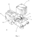
FIG. 1 is a three-dimensional view of a preferred embodiment of the invention; -
FIG. 2 is an exploded view of a first preferred embodiment of the invention; -
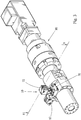
FIG. 3 is a three-dimensional view of the first preferred embodiment of the invention applied to a polymer injection machine; -
FIG. 4 is a sectional view of the first preferred embodiment of the invention taken along the sectional line a-a inFIG. 3 , in which the first valve stem and the second valve stem are respectively in a closed position; -
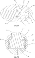
FIG. 4 (A) is a partial enlarged view showing the area A inFIG. 4 ; -
FIG. 4 (B) is a partial enlarged view showing the area B inFIG. 4 ; -
FIG. 5 is a sectional view of the first preferred embodiment of the invention taken along the sectional line a-a inFIG. 3 , in which the first valve stem and the second valve stem are respectively in an opened position; -
FIG. 5 (A) is a partial enlarged view showing the area A inFIG. 5 ; -
FIG. 5 (B) is a partial enlarged view showing the area B inFIG. 5 ; -
FIG. 6 is a three-dimensional view of a second preferred embodiment of the invention; -
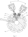
FIG. 7 is a sectional view of the second preferred embodiment of the invention taken along the sectional line 7-7 inFIG. 6 ; -
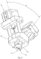
FIG. 8 is a three-dimensional bottom view of the second preferred embodiment of the invention; and -
FIG. 9 is a three-dimensional bottom view showing a partial section of the second preferred embodiment of the invention. - First, with reference to
FIGS. 1 and2 , a valve (10) according to a preferred embodiment of the invention comprises essentially a seat (20), a first channel (30), a second channel (40), an inflow channel (50), an outflow channel (60), a first valve piece (70), and a second valve piece (80). - The seat (20) is a block having a shape and configuration that can be assembled and joined to other elements and a strength that can withstand the high pressure of the fluid. The seat (20) is joined to an extrusion barrel or a mixing barrel of a polymer injection machine (90) shown in
FIG. 3 and serves as part of a supply path for external fluid to be supplied into the extrusion barrel or the mixing barrel and mixed with the polymer material, and also as a base on which other constituent elements of the valve (10) are provided. In the technique of polymer molding and processing, the so-called external fluid is, for example, super-critical fluid, color Masterbatch, color paste, or any other additive in the state of fluid. - The first channel (30) and the outflow channel (60) are straight holes passing through the seat (20) in coaxial communication with each other. Specifically, the outflow channel (60) has an outflow segment (61) extending inwardly from the end face of an underside of the seat (20) to a suitable depth. A tapered segment (62) in the shape of a cone-shaped hole is positioned inside the seat (20) and connects the outflow segment (61) to the first channel (30). The inner diameter of the outflow segment (61) is larger than that of the first channel (30), so that the inner wall face (621) of the tapered segment (62) faces the outflow segment (61).
- The second channel (40) is a straight hole that extends inwardly from the left end face of the seat (20) and is in communication with and perpendicular to a middle portion of the first channel (30). Further, the second channel (40) is segmented in sequence along the hole axis into a main body segment (41) in communication with the outside on the left end face of the seat (20), a connection segment (42) of an inner diameter smaller than that of the main body segment (41) and connecting the main body segment (41) to the first channel (30), and a shoulder face (43) between the main body segment (41) and the connection segment (42).
- The inflow channel (50) extends from the top end of the seat (20) downwardly and obliquely to a location on the main body segment (41) close to the shoulder face (43) .
- The first valve piece (70) has a first valve stem (71) in the shape of a straight bar that passes coaxially through the first channel (30) and the outflow channel (60). Its top end extends above the seat (20) and its bottom end is positioned in the outflow channel (60). A first hydraulic cylinder (72) has an output shaft (721) pressed against the top end of the first valve stem (71). A compression spring (73) is sleeved over the portion of the first valve stem (71) that extends out of the seat (20), and provides an elastic force for the first valve stem (71) to move upwardly.
- Further, the first valve stem (71) is segmented along its stem axis into a main shaft segment (711) disposed slidably in the first channel (30), an extended segment (712) extending into the outflow channel (60), and an annular tapered face (713) between the main shaft segment (711) and the extended segment (712). The tapered face (713) is opposite to the inner wall face (621) of the tapered segment (62) and has the same tapering slope as it. The main shaft segment (711) has an outer diameter smaller than the inner diameter of the first channel (30), and the extended segment (712) has an outer diameter smaller than the inner diameter of the outflow segment (61) .
- The second valve piece (80) has a second valve stem (81) in the shape of a straight bar that passes slidably and coaxially through the main body segment (41) of the second channel (40) with its left end extending out of the left end face of the seat (20). A second hydraulic cylinder (82) has an output shaft (821) pressed against the left end of the second valve stem (81).
- Still further, the second valve stem (81) is segmented in sequence along its stem axis into a shaft body segment (811) disposed slidably in the second channel (40) and a cone-ended segment (812) is a tapered shape between the shaft body segment (811) and the connection segment (42) .
- In addition, the specific configuration and arrangement or coupling with other elements and the like of the first hydraulic cylinder (72) and the second hydraulic cylinder (82) are well known in the art. They are illustrated merely as the power source for actuation of the valve in the present embodiment. Therefore, although some parts are not fully depicted in the figures, they will not affect implementation of the invention by those of ordinary skills in the art.
- With the configuration of the members described above, the first valve stem (71) can be moved back and forth axially in the first channel (30) and the outflow channel (60) along its stem axis between a first closed position and a first opened position. The second valve stem (81) can be moved back and forth axially in the second channel (40) along its stem axis between a second closed position and a second opened position. Generally, when the first valve stem (71) is in the first closed position and the second valve stem (81) is in the second closed position, the communication between the inflow channel (50) and the first channel (30) as well as the communication between the first channel (30) and the outflow segment (61) are blocked as shown in
FIG. 4 . On the contrary, when the first valve stem (71) is in the first opened position and the second valve stem (81) is in the second opened position, the whole passageway, from the inflow channel (50), through the second channel (40) and the first channel (30) in sequence, to the outflow channel (60), is unblocked as shown inFIG. 5 . In this way, the valve (10) can control flow of the fluid, so as to control the amount of fluid entering the extrusion barrel or the mixing barrel of the polymer injection machine (90) to be mixed with the polymer material. - With reference to
FIGS. 5 ,5(A), and 5(B) , as for the axial movement of the first valve stem (71), the elastic force of the compression spring (73) maintains the first valve stem (71) elastically in the first closed position. As shown inFIG. 4 , when the first valve stem (71) is in the first closed position, the tapered face (713) is in close contact with the inner wall face (621), thereby blocking the communication between the outflow segment (61) and the first channel (30). On the contrary, when power is supplied from the first hydraulic cylinder (72) to push the first valve stem (71) downward via the output shaft (721) so as to cause the first valve stem (71) to move axially to the first opened position as shown inFIG. 5 , the tapered face (713) and the inner wall face (621) are separated from each other. Also, since the outer diameter of the main shaft segment (711) is smaller than that of the first channel (30) and the outer diameter of the extended segment (712) is smaller than that of the outflow segment (61), such a difference in size provides a gap therebetween for the fluid to flow therein. - Still further, with reference to
FIGS. 4 ,4(A) , and 4(B), as for the axial movement of the second valve stem (81), an external force from the second hydraulic cylinder (82) pushes the second valve stem (81) to the right till the second closed position as shown inFIG. 4 . At this point, the end of the cone-ended segment (812) extends from the main body segment (41) into the connection segment (42), with the tapered face at the circumferential side being pressed against the opening in the connection segment (42) connected to the main body segment (41), thereby blocking the communication between the main body segment (41) and the connection segment (42) . Meanwhile, a space (s) between the circumferential side of the cone-ended segment (812) and the inner wall face of the main body segment (41) remains in communication with the inflow channel (50), thereby allowing the space (s) to be filled with the fluid that is still in communication with an external fluid supply via the inflow channel (50) . In other words, in this space (s), high pressure of the fluid acts continuously on the circumferential side face of the cone-ended segment (812). Therefore, once the external force applied by the second hydraulic cylinder (82) is released, the pressure of the fluid in the space (s) pushes the second valve stem (81) to the left till the second opened position as shown inFIG. 5 , thereby allowing the inflow channel (50) to be in communication indirectly with the first channel (30) via the second channel (40). - Further, with reference to
FIGS. 6 and7 , the valve (10a) according to the second preferred embodiment of the invention has the same essential technical characteristics as the one disclosed in the first preferred embodiment described above, but has better efficacy than the first preferred embodiment in maintaining the temperature of the fluid. - Specifically, as disclosed in this embodiment, the second channel (40a) and the first channel (30a) are in communication with each other with an acute included angle (α) therebetween, so that the connection segment (42a) is positioned closer to the center of the extrusion barrel or the mixing barrel of the polymer injection machine (90a). In this way, heat generated during operation of the extrusion barrel or the mixing barrel of the polymer injection machine (90a) can be utilized to maintain the temperature of the fluid, thereby reducing temperature loss of the fluid.
- In order to further maintain the temperature of the fluid, and with reference to
FIGS. 8 and9 , in this embodiment, an approximately V-shaped connection is made between the second channel (40a) and the first channel (30a) to allow the portions of the channels connected to be positioned inside an insertion pillar (21a) protruding from the bottom end of the seat (20a) . As such, once the insertion pillar (21a) of the seat (20a) is inserted into an insertion hole (91a) in the extrusion barrel or mixing barrel of the polymer injection machine (90a) and the seat (20a) is thus joined to the extrusion barrel or mixing barrel of the polymer injection machine (90a), the portions of the channels connected are covered by the extrusion barrel or mixing barrel of the polymer injection machine (90a), thereby avoiding temperature loss due to contact with the surroundings. - In addition, in this embodiment, the outflow segment (61a) of the outflow channel (60a) is further in communication with an undercut (22a) provided at the end of the insertion pillar (21a), so that the fluid flowing out via the outflow segment (61a) is dispersed via the undercut (22a) and then fed evenly into the extrusion barrel or mixing barrel of the polymer injection machine (90a) and mixed with the raw material.
Claims (12)
- A valve (10) positioned in a fluid supply path to control opening and closing of the supply path, comprising:a seat (20);a first channel (30) disposed in the seat (20);a second channel (40) disposed in the seat (20) and in communication with the first channel;an inflow channel (50) disposed in the seat (20) and in communication with the second channel (40), and also in communication indirectly with the first channel (30) via the second channel (40);an outflow channel (60) disposed in the seat (20) and in communication with the first channel (30, and also in communication indirectly with the inflow channel via the first channel (30) and the second channel (40);a first valve piece (70) disposed movably in the first channel (30), wherein the first valve piece (70) can be moved between a first closed position and a first opened position, in which when the first valve piece (70) is in the first closed position, the communication between the first channel (30) and the outflow channel (60) is blocked, whereas when the first valve piece (70) is in the first opened position, the first channel (30) and the outflow channel (60) are put in communication with each other;a second valve piece (80) disposed movably in the second channel (40), wherein the second valve piece (80) can be moved between a second closed position and a second opened position, in which when the second valve piece (80) is in the second closed position, the communication between the inflow channel (50) and the first channel (30) is blocked, whereas when the second valve piece (80) is in the second opened position, the first channel (30) and the inflow channel (50) are put in communication with each other characterized in thatthe seat (20) is configured to be joined to an extrusion barrel or mixing barrel of a polymer injection machine (90) so as to form a part of a supply path for an external fluid to be supplied into the extrusion barrel or the mixing barrel.
- The valve of claim 1, wherein the first valve piece (70) has a first valve stem (71) disposed slidably in the first channel (30) that can be moved axially back and forth along its stem axis between the first closed position and the first opened position.
- The valve of claim 2, wherein the first valve stem (71) is segmented in sequence along its stem axis into a main shaft segment (711) positioned in the first channel (30), an extended segment (712) positioned in the outflow channel (60), and an annular tapered face (713) between the main shaft segment (711) and the extended segment (712) .
- The valve of claim 3, wherein:the outflow channel (60) has an outflow segment (61) of an inner diameter larger than the inner diameter of the first channel (30) and the outer diameter of the extended segment (712) and a tapered segment (62) connecting the outflow segment (61) to the first channel (30), the inner wall face (621) of the tapered segment (62) having the same tapering slope as the tapered face (713); andwhen the first valve stem (71) is in the first closed position, the tapered face (713) is in close contact with the inner wall face (621) of the tapered segment (62) to block the tapered segment (62), whereas when the first valve stem (71) is in the first opened position, the tapered face (713) is separated from the inner wall face (621) of the tapered segment (62).
- The valve of claim 4, wherein the first channel (30) and the outflow channel (60) pass through the seat in coaxial communication with each other.
- The valve of claim 1, wherein the second channel (40) has a main body segment (41) and a connection segment (42) connecting the main body segment (41) to the first channel (30), the connection segment (42) having an inner diameter smaller than the inner diameter of the main body segment (41) so as to form an opening in communication with the main body segment (41).
- The valve of claim 6, wherein the inflow channel (50) is connected to the main body segment (41) ataposition adjacent to the connection segment (42).
- The valve of claim 7, wherein the second valve piece (80) has a second valve stem (81) disposed slidably in the main body segment (41) that can be moved axially back and forth along its stem axis between the second closed position and the second opened position.
- The valve of claim 8, wherein:the second valve stem (81) is segmented in sequence along its stem axis into a shaft body segment (811) positioned in the main body segment (41) and a cone-ended segment (812) in a tapered shape, the end of the cone-ended segment (812) capable of being extended into the connect ion segment (42);when the second valve stem (81) is in the second closed position, the end of the cone-ended segment (812) is positioned in the connection segment (42), while the tapered bevel at the circumferential side of the cone-ended segment (812) is pressed against the opening in the connection segment (42), so as to block the communication between the connection segment (42) and the main body segment (41); andwhen the second valve stem (81) is in the second opened position, the tapered bevel at the circumferential side of the cone-ended segment (812) is separated from the opening in the connection segment (42), so as to put the main body segment (41) and the connection segment in communication with each other.
- The valve of claim. 9, wherein when the second valve stem (81) is in the second closed position, the space between the inner side wall face (621) of the main body segment (41) and the tapered bevel at the circumferential side of the cone-ended segment (812) is in communication with the inflow channel (50).
- The valve of claim 1, wherein the first channel (30) and the second channel (40) are in communication with and perpendicular to each other.
- The valve of claim 1, wherein the first channel (30) and the second channel (40) are in communication with each other and separated by an acute included angle.
Applications Claiming Priority (2)
| Application Number | Priority Date | Filing Date | Title |
|---|---|---|---|
| TW107129970 | 2018-08-28 | ||
| TW107131644A TWI676754B (en) | 2018-08-28 | 2018-09-08 | valve |
Publications (2)
| Publication Number | Publication Date |
|---|---|
| EP3616877A1 EP3616877A1 (en) | 2020-03-04 |
| EP3616877B1 true EP3616877B1 (en) | 2021-09-29 |
Family
ID=67438461
Family Applications (1)
| Application Number | Title | Priority Date | Filing Date |
|---|---|---|---|
| EP19187665.5A Active EP3616877B1 (en) | 2018-08-28 | 2019-07-22 | Valve |
Country Status (1)
| Country | Link |
|---|---|
| EP (1) | EP3616877B1 (en) |
Family Cites Families (6)
| Publication number | Priority date | Publication date | Assignee | Title |
|---|---|---|---|---|
| US5972258A (en) * | 1997-10-20 | 1999-10-26 | Husky Injection Molding Systems Ltd. | Method of using a multiple gating nozzle |
| JP3285830B2 (en) * | 1998-10-26 | 2002-05-27 | 積水化学工業株式会社 | Method for producing thermoplastic resin molded article and apparatus for producing thermoplastic resin molded article used in this production method |
| EP1052078A1 (en) * | 1999-05-08 | 2000-11-15 | HEKUMA Herbst Maschinenbau GmbH | Individual process control in a mould |
| AU2002232714A1 (en) | 2000-10-24 | 2002-05-06 | Trexel, Inc. | Valve for injection molding |
| US7175420B2 (en) * | 2003-02-13 | 2007-02-13 | Mold-Masters Limited | Valve gated injection molding system with independent flow control |
| CA2782963C (en) * | 2009-12-31 | 2015-03-24 | Husky Injection Molding Systems Ltd. | Mold-runner system having independently controllable shooting-pot assemblies |
-
2019
- 2019-07-22 EP EP19187665.5A patent/EP3616877B1/en active Active
Also Published As
| Publication number | Publication date |
|---|---|
| EP3616877A1 (en) | 2020-03-04 |
Similar Documents
| Publication | Publication Date | Title |
|---|---|---|
| CN101203704B (en) | Movable bolt | |
| KR100768868B1 (en) | Fluid pressure cylinder apparatus having throttle valve | |
| US3033227A (en) | Ball valve | |
| US20110297262A1 (en) | Hydraulic valve | |
| EP2947359B1 (en) | Knife gate valve | |
| CN101636609B (en) | Regulating valve | |
| US20030140974A1 (en) | Pilot control valve | |
| EP3616877B1 (en) | Valve | |
| CN106996471B (en) | Directional valve with check valve function | |
| US11131391B2 (en) | Valve | |
| US6016838A (en) | Valve construction | |
| US5328148A (en) | Control device for hydraulic piston/cylinder unit | |
| US3990680A (en) | Valve construction and method of making the same | |
| CA2434333A1 (en) | Rotatable seal for ball valve | |
| CN107178621B (en) | Stop valve for refrigerating system and valve rod thereof | |
| US2192835A (en) | Valve for controlling fluids | |
| CN220566584U (en) | Control valve | |
| CN110886855A (en) | Valve with a valve body | |
| US5172886A (en) | Fluid flow control valve assembly | |
| KR101205597B1 (en) | Gas regulating valve for torch | |
| TWI778012B (en) | Sealing system of a device for allowing the passage of a medium, in particular in the high pressure range | |
| US4054979A (en) | Valve construction and method of making the same | |
| US10436330B2 (en) | Non-rising stem globe valve | |
| CA2561524A1 (en) | Screw tip and molding system apparatus | |
| US20200232565A1 (en) | Intermitter valve |
Legal Events
| Date | Code | Title | Description |
|---|---|---|---|
| PUAI | Public reference made under article 153(3) epc to a published international application that has entered the european phase |
Free format text: ORIGINAL CODE: 0009012 |
|
| STAA | Information on the status of an ep patent application or granted ep patent |
Free format text: STATUS: THE APPLICATION HAS BEEN PUBLISHED |
|
| AK | Designated contracting states |
Kind code of ref document: A1 Designated state(s): AL AT BE BG CH CY CZ DE DK EE ES FI FR GB GR HR HU IE IS IT LI LT LU LV MC MK MT NL NO PL PT RO RS SE SI SK SM TR |
|
| AX | Request for extension of the european patent |
Extension state: BA ME |
|
| STAA | Information on the status of an ep patent application or granted ep patent |
Free format text: STATUS: REQUEST FOR EXAMINATION WAS MADE |
|
| 17P | Request for examination filed |
Effective date: 20200806 |
|
| RBV | Designated contracting states (corrected) |
Designated state(s): AL AT BE BG CH CY CZ DE DK EE ES FI FR GB GR HR HU IE IS IT LI LT LU LV MC MK MT NL NO PL PT RO RS SE SI SK SM TR |
|
| GRAP | Despatch of communication of intention to grant a patent |
Free format text: ORIGINAL CODE: EPIDOSNIGR1 |
|
| STAA | Information on the status of an ep patent application or granted ep patent |
Free format text: STATUS: GRANT OF PATENT IS INTENDED |
|
| INTG | Intention to grant announced |
Effective date: 20210408 |
|
| GRAS | Grant fee paid |
Free format text: ORIGINAL CODE: EPIDOSNIGR3 |
|
| GRAA | (expected) grant |
Free format text: ORIGINAL CODE: 0009210 |
|
| STAA | Information on the status of an ep patent application or granted ep patent |
Free format text: STATUS: THE PATENT HAS BEEN GRANTED |
|
| AK | Designated contracting states |
Kind code of ref document: B1 Designated state(s): AL AT BE BG CH CY CZ DE DK EE ES FI FR GB GR HR HU IE IS IT LI LT LU LV MC MK MT NL NO PL PT RO RS SE SI SK SM TR |
|
| REG | Reference to a national code |
Ref country code: GB Ref legal event code: FG4D |
|
| REG | Reference to a national code |
Ref country code: CH Ref legal event code: EP Ref country code: AT Ref legal event code: REF Ref document number: 1433823 Country of ref document: AT Kind code of ref document: T Effective date: 20211015 |
|
| REG | Reference to a national code |
Ref country code: DE Ref legal event code: R096 Ref document number: 602019007953 Country of ref document: DE |
|
| REG | Reference to a national code |
Ref country code: IE Ref legal event code: FG4D |
|
| REG | Reference to a national code |
Ref country code: LT Ref legal event code: MG9D |
|
| PG25 | Lapsed in a contracting state [announced via postgrant information from national office to epo] |
Ref country code: BG Free format text: LAPSE BECAUSE OF FAILURE TO SUBMIT A TRANSLATION OF THE DESCRIPTION OR TO PAY THE FEE WITHIN THE PRESCRIBED TIME-LIMIT Effective date: 20211229 Ref country code: LT Free format text: LAPSE BECAUSE OF FAILURE TO SUBMIT A TRANSLATION OF THE DESCRIPTION OR TO PAY THE FEE WITHIN THE PRESCRIBED TIME-LIMIT Effective date: 20210929 Ref country code: HR Free format text: LAPSE BECAUSE OF FAILURE TO SUBMIT A TRANSLATION OF THE DESCRIPTION OR TO PAY THE FEE WITHIN THE PRESCRIBED TIME-LIMIT Effective date: 20210929 Ref country code: NO Free format text: LAPSE BECAUSE OF FAILURE TO SUBMIT A TRANSLATION OF THE DESCRIPTION OR TO PAY THE FEE WITHIN THE PRESCRIBED TIME-LIMIT Effective date: 20211229 Ref country code: RS Free format text: LAPSE BECAUSE OF FAILURE TO SUBMIT A TRANSLATION OF THE DESCRIPTION OR TO PAY THE FEE WITHIN THE PRESCRIBED TIME-LIMIT Effective date: 20210929 Ref country code: SE Free format text: LAPSE BECAUSE OF FAILURE TO SUBMIT A TRANSLATION OF THE DESCRIPTION OR TO PAY THE FEE WITHIN THE PRESCRIBED TIME-LIMIT Effective date: 20210929 Ref country code: FI Free format text: LAPSE BECAUSE OF FAILURE TO SUBMIT A TRANSLATION OF THE DESCRIPTION OR TO PAY THE FEE WITHIN THE PRESCRIBED TIME-LIMIT Effective date: 20210929 |
|
| REG | Reference to a national code |
Ref country code: NL Ref legal event code: MP Effective date: 20210929 |
|
| REG | Reference to a national code |
Ref country code: AT Ref legal event code: MK05 Ref document number: 1433823 Country of ref document: AT Kind code of ref document: T Effective date: 20210929 |
|
| PG25 | Lapsed in a contracting state [announced via postgrant information from national office to epo] |
Ref country code: LV Free format text: LAPSE BECAUSE OF FAILURE TO SUBMIT A TRANSLATION OF THE DESCRIPTION OR TO PAY THE FEE WITHIN THE PRESCRIBED TIME-LIMIT Effective date: 20210929 Ref country code: GR Free format text: LAPSE BECAUSE OF FAILURE TO SUBMIT A TRANSLATION OF THE DESCRIPTION OR TO PAY THE FEE WITHIN THE PRESCRIBED TIME-LIMIT Effective date: 20211230 |
|
| PG25 | Lapsed in a contracting state [announced via postgrant information from national office to epo] |
Ref country code: AT Free format text: LAPSE BECAUSE OF FAILURE TO SUBMIT A TRANSLATION OF THE DESCRIPTION OR TO PAY THE FEE WITHIN THE PRESCRIBED TIME-LIMIT Effective date: 20210929 |
|
| PG25 | Lapsed in a contracting state [announced via postgrant information from national office to epo] |
Ref country code: IS Free format text: LAPSE BECAUSE OF FAILURE TO SUBMIT A TRANSLATION OF THE DESCRIPTION OR TO PAY THE FEE WITHIN THE PRESCRIBED TIME-LIMIT Effective date: 20220129 Ref country code: SK Free format text: LAPSE BECAUSE OF FAILURE TO SUBMIT A TRANSLATION OF THE DESCRIPTION OR TO PAY THE FEE WITHIN THE PRESCRIBED TIME-LIMIT Effective date: 20210929 Ref country code: RO Free format text: LAPSE BECAUSE OF FAILURE TO SUBMIT A TRANSLATION OF THE DESCRIPTION OR TO PAY THE FEE WITHIN THE PRESCRIBED TIME-LIMIT Effective date: 20210929 Ref country code: PT Free format text: LAPSE BECAUSE OF FAILURE TO SUBMIT A TRANSLATION OF THE DESCRIPTION OR TO PAY THE FEE WITHIN THE PRESCRIBED TIME-LIMIT Effective date: 20220131 Ref country code: PL Free format text: LAPSE BECAUSE OF FAILURE TO SUBMIT A TRANSLATION OF THE DESCRIPTION OR TO PAY THE FEE WITHIN THE PRESCRIBED TIME-LIMIT Effective date: 20210929 Ref country code: NL Free format text: LAPSE BECAUSE OF FAILURE TO SUBMIT A TRANSLATION OF THE DESCRIPTION OR TO PAY THE FEE WITHIN THE PRESCRIBED TIME-LIMIT Effective date: 20210929 Ref country code: ES Free format text: LAPSE BECAUSE OF FAILURE TO SUBMIT A TRANSLATION OF THE DESCRIPTION OR TO PAY THE FEE WITHIN THE PRESCRIBED TIME-LIMIT Effective date: 20210929 Ref country code: EE Free format text: LAPSE BECAUSE OF FAILURE TO SUBMIT A TRANSLATION OF THE DESCRIPTION OR TO PAY THE FEE WITHIN THE PRESCRIBED TIME-LIMIT Effective date: 20210929 Ref country code: CZ Free format text: LAPSE BECAUSE OF FAILURE TO SUBMIT A TRANSLATION OF THE DESCRIPTION OR TO PAY THE FEE WITHIN THE PRESCRIBED TIME-LIMIT Effective date: 20210929 Ref country code: AL Free format text: LAPSE BECAUSE OF FAILURE TO SUBMIT A TRANSLATION OF THE DESCRIPTION OR TO PAY THE FEE WITHIN THE PRESCRIBED TIME-LIMIT Effective date: 20210929 |
|
| REG | Reference to a national code |
Ref country code: DE Ref legal event code: R097 Ref document number: 602019007953 Country of ref document: DE |
|
| PG25 | Lapsed in a contracting state [announced via postgrant information from national office to epo] |
Ref country code: DK Free format text: LAPSE BECAUSE OF FAILURE TO SUBMIT A TRANSLATION OF THE DESCRIPTION OR TO PAY THE FEE WITHIN THE PRESCRIBED TIME-LIMIT Effective date: 20210929 |
|
| PLBE | No opposition filed within time limit |
Free format text: ORIGINAL CODE: 0009261 |
|
| STAA | Information on the status of an ep patent application or granted ep patent |
Free format text: STATUS: NO OPPOSITION FILED WITHIN TIME LIMIT |
|
| 26N | No opposition filed |
Effective date: 20220630 |
|
| PG25 | Lapsed in a contracting state [announced via postgrant information from national office to epo] |
Ref country code: SI Free format text: LAPSE BECAUSE OF FAILURE TO SUBMIT A TRANSLATION OF THE DESCRIPTION OR TO PAY THE FEE WITHIN THE PRESCRIBED TIME-LIMIT Effective date: 20210929 |
|
| PG25 | Lapsed in a contracting state [announced via postgrant information from national office to epo] |
Ref country code: MC Free format text: LAPSE BECAUSE OF FAILURE TO SUBMIT A TRANSLATION OF THE DESCRIPTION OR TO PAY THE FEE WITHIN THE PRESCRIBED TIME-LIMIT Effective date: 20210929 |
|
| REG | Reference to a national code |
Ref country code: CH Ref legal event code: PL |
|
| REG | Reference to a national code |
Ref country code: BE Ref legal event code: MM Effective date: 20220731 |
|
| PG25 | Lapsed in a contracting state [announced via postgrant information from national office to epo] |
Ref country code: LU Free format text: LAPSE BECAUSE OF NON-PAYMENT OF DUE FEES Effective date: 20220722 Ref country code: LI Free format text: LAPSE BECAUSE OF NON-PAYMENT OF DUE FEES Effective date: 20220731 Ref country code: FR Free format text: LAPSE BECAUSE OF NON-PAYMENT OF DUE FEES Effective date: 20220731 Ref country code: CH Free format text: LAPSE BECAUSE OF NON-PAYMENT OF DUE FEES Effective date: 20220731 |
|
| PG25 | Lapsed in a contracting state [announced via postgrant information from national office to epo] |
Ref country code: BE Free format text: LAPSE BECAUSE OF NON-PAYMENT OF DUE FEES Effective date: 20220731 |
|
| PG25 | Lapsed in a contracting state [announced via postgrant information from national office to epo] |
Ref country code: IE Free format text: LAPSE BECAUSE OF NON-PAYMENT OF DUE FEES Effective date: 20220722 |
|
| PGFP | Annual fee paid to national office [announced via postgrant information from national office to epo] |
Ref country code: IT Payment date: 20230731 Year of fee payment: 5 |
|
| PGFP | Annual fee paid to national office [announced via postgrant information from national office to epo] |
Ref country code: DE Payment date: 20230724 Year of fee payment: 5 |
|
| GBPC | Gb: european patent ceased through non-payment of renewal fee |
Effective date: 20230722 |
|
| PG25 | Lapsed in a contracting state [announced via postgrant information from national office to epo] |
Ref country code: HU Free format text: LAPSE BECAUSE OF FAILURE TO SUBMIT A TRANSLATION OF THE DESCRIPTION OR TO PAY THE FEE WITHIN THE PRESCRIBED TIME-LIMIT; INVALID AB INITIO Effective date: 20190722 |