EP3616735B1 - Drug delivery system with sensor having optimized communication and infusion site - Google Patents
Drug delivery system with sensor having optimized communication and infusion site Download PDFInfo
- Publication number
- EP3616735B1 EP3616735B1 EP19194241.6A EP19194241A EP3616735B1 EP 3616735 B1 EP3616735 B1 EP 3616735B1 EP 19194241 A EP19194241 A EP 19194241A EP 3616735 B1 EP3616735 B1 EP 3616735B1
- Authority
- EP
- European Patent Office
- Prior art keywords
- drug delivery
- delivery device
- sensor
- cgm sensor
- cannula
- Prior art date
- Legal status (The legal status is an assumption and is not a legal conclusion. Google has not performed a legal analysis and makes no representation as to the accuracy of the status listed.)
- Active
Links
- 238000012377 drug delivery Methods 0.000 title claims description 265
- 238000001802 infusion Methods 0.000 title claims description 46
- 238000004891 communication Methods 0.000 title description 19
- 239000003814 drug Substances 0.000 claims description 13
- 229940079593 drug Drugs 0.000 claims description 9
- WQZGKKKJIJFFOK-GASJEMHNSA-N Glucose Natural products OC[C@H]1OC(O)[C@H](O)[C@@H](O)[C@@H]1O WQZGKKKJIJFFOK-GASJEMHNSA-N 0.000 claims description 8
- 239000008103 glucose Substances 0.000 claims description 8
- NOESYZHRGYRDHS-UHFFFAOYSA-N insulin Chemical compound N1C(=O)C(NC(=O)C(CCC(N)=O)NC(=O)C(CCC(O)=O)NC(=O)C(C(C)C)NC(=O)C(NC(=O)CN)C(C)CC)CSSCC(C(NC(CO)C(=O)NC(CC(C)C)C(=O)NC(CC=2C=CC(O)=CC=2)C(=O)NC(CCC(N)=O)C(=O)NC(CC(C)C)C(=O)NC(CCC(O)=O)C(=O)NC(CC(N)=O)C(=O)NC(CC=2C=CC(O)=CC=2)C(=O)NC(CSSCC(NC(=O)C(C(C)C)NC(=O)C(CC(C)C)NC(=O)C(CC=2C=CC(O)=CC=2)NC(=O)C(CC(C)C)NC(=O)C(C)NC(=O)C(CCC(O)=O)NC(=O)C(C(C)C)NC(=O)C(CC(C)C)NC(=O)C(CC=2NC=NC=2)NC(=O)C(CO)NC(=O)CNC2=O)C(=O)NCC(=O)NC(CCC(O)=O)C(=O)NC(CCCNC(N)=N)C(=O)NCC(=O)NC(CC=3C=CC=CC=3)C(=O)NC(CC=3C=CC=CC=3)C(=O)NC(CC=3C=CC(O)=CC=3)C(=O)NC(C(C)O)C(=O)N3C(CCC3)C(=O)NC(CCCCN)C(=O)NC(C)C(O)=O)C(=O)NC(CC(N)=O)C(O)=O)=O)NC(=O)C(C(C)CC)NC(=O)C(CO)NC(=O)C(C(C)O)NC(=O)C1CSSCC2NC(=O)C(CC(C)C)NC(=O)C(NC(=O)C(CCC(N)=O)NC(=O)C(CC(N)=O)NC(=O)C(NC(=O)C(N)CC=1C=CC=CC=1)C(C)C)CC1=CN=CN1 NOESYZHRGYRDHS-UHFFFAOYSA-N 0.000 claims description 8
- 239000007788 liquid Substances 0.000 claims description 7
- 102000004877 Insulin Human genes 0.000 claims description 4
- 108090001061 Insulin Proteins 0.000 claims description 4
- 229940125396 insulin Drugs 0.000 claims description 4
- 239000000853 adhesive Substances 0.000 description 59
- 230000001070 adhesive effect Effects 0.000 description 59
- 238000000034 method Methods 0.000 description 17
- 241001631457 Cannula Species 0.000 description 9
- 230000001954 sterilising effect Effects 0.000 description 8
- 238000004659 sterilization and disinfection Methods 0.000 description 8
- 230000005540 biological transmission Effects 0.000 description 5
- 230000008569 process Effects 0.000 description 5
- 238000005259 measurement Methods 0.000 description 4
- 238000012544 monitoring process Methods 0.000 description 4
- 239000002547 new drug Substances 0.000 description 4
- 230000005855 radiation Effects 0.000 description 3
- 229940124597 therapeutic agent Drugs 0.000 description 3
- IAYPIBMASNFSPL-UHFFFAOYSA-N Ethylene oxide Chemical compound C1CO1 IAYPIBMASNFSPL-UHFFFAOYSA-N 0.000 description 2
- 230000008878 coupling Effects 0.000 description 2
- 238000010168 coupling process Methods 0.000 description 2
- 238000005859 coupling reaction Methods 0.000 description 2
- 230000036541 health Effects 0.000 description 2
- 230000003287 optical effect Effects 0.000 description 2
- 230000002457 bidirectional effect Effects 0.000 description 1
- 239000000470 constituent Substances 0.000 description 1
- 238000007726 management method Methods 0.000 description 1
- 230000007246 mechanism Effects 0.000 description 1
- 238000005086 pumping Methods 0.000 description 1
Images


Classifications
-
- A—HUMAN NECESSITIES
- A61—MEDICAL OR VETERINARY SCIENCE; HYGIENE
- A61M—DEVICES FOR INTRODUCING MEDIA INTO, OR ONTO, THE BODY; DEVICES FOR TRANSDUCING BODY MEDIA OR FOR TAKING MEDIA FROM THE BODY; DEVICES FOR PRODUCING OR ENDING SLEEP OR STUPOR
- A61M5/00—Devices for bringing media into the body in a subcutaneous, intra-vascular or intramuscular way; Accessories therefor, e.g. filling or cleaning devices, arm-rests
- A61M5/14—Infusion devices, e.g. infusing by gravity; Blood infusion; Accessories therefor
- A61M5/142—Pressure infusion, e.g. using pumps
- A61M5/14244—Pressure infusion, e.g. using pumps adapted to be carried by the patient, e.g. portable on the body
- A61M5/14248—Pressure infusion, e.g. using pumps adapted to be carried by the patient, e.g. portable on the body of the skin patch type
-
- A—HUMAN NECESSITIES
- A61—MEDICAL OR VETERINARY SCIENCE; HYGIENE
- A61M—DEVICES FOR INTRODUCING MEDIA INTO, OR ONTO, THE BODY; DEVICES FOR TRANSDUCING BODY MEDIA OR FOR TAKING MEDIA FROM THE BODY; DEVICES FOR PRODUCING OR ENDING SLEEP OR STUPOR
- A61M5/00—Devices for bringing media into the body in a subcutaneous, intra-vascular or intramuscular way; Accessories therefor, e.g. filling or cleaning devices, arm-rests
- A61M5/14—Infusion devices, e.g. infusing by gravity; Blood infusion; Accessories therefor
- A61M5/168—Means for controlling media flow to the body or for metering media to the body, e.g. drip meters, counters ; Monitoring media flow to the body
- A61M5/16831—Monitoring, detecting, signalling or eliminating infusion flow anomalies
- A61M5/16836—Monitoring, detecting, signalling or eliminating infusion flow anomalies by sensing tissue properties at the infusion site, e.g. for detecting infiltration
-
- A—HUMAN NECESSITIES
- A61—MEDICAL OR VETERINARY SCIENCE; HYGIENE
- A61B—DIAGNOSIS; SURGERY; IDENTIFICATION
- A61B5/00—Measuring for diagnostic purposes; Identification of persons
- A61B5/145—Measuring characteristics of blood in vivo, e.g. gas concentration, pH value; Measuring characteristics of body fluids or tissues, e.g. interstitial fluid, cerebral tissue
- A61B5/14532—Measuring characteristics of blood in vivo, e.g. gas concentration, pH value; Measuring characteristics of body fluids or tissues, e.g. interstitial fluid, cerebral tissue for measuring glucose, e.g. by tissue impedance measurement
-
- A—HUMAN NECESSITIES
- A61—MEDICAL OR VETERINARY SCIENCE; HYGIENE
- A61M—DEVICES FOR INTRODUCING MEDIA INTO, OR ONTO, THE BODY; DEVICES FOR TRANSDUCING BODY MEDIA OR FOR TAKING MEDIA FROM THE BODY; DEVICES FOR PRODUCING OR ENDING SLEEP OR STUPOR
- A61M5/00—Devices for bringing media into the body in a subcutaneous, intra-vascular or intramuscular way; Accessories therefor, e.g. filling or cleaning devices, arm-rests
- A61M5/14—Infusion devices, e.g. infusing by gravity; Blood infusion; Accessories therefor
- A61M5/142—Pressure infusion, e.g. using pumps
- A61M5/14244—Pressure infusion, e.g. using pumps adapted to be carried by the patient, e.g. portable on the body
-
- A—HUMAN NECESSITIES
- A61—MEDICAL OR VETERINARY SCIENCE; HYGIENE
- A61M—DEVICES FOR INTRODUCING MEDIA INTO, OR ONTO, THE BODY; DEVICES FOR TRANSDUCING BODY MEDIA OR FOR TAKING MEDIA FROM THE BODY; DEVICES FOR PRODUCING OR ENDING SLEEP OR STUPOR
- A61M5/00—Devices for bringing media into the body in a subcutaneous, intra-vascular or intramuscular way; Accessories therefor, e.g. filling or cleaning devices, arm-rests
- A61M5/14—Infusion devices, e.g. infusing by gravity; Blood infusion; Accessories therefor
- A61M5/168—Means for controlling media flow to the body or for metering media to the body, e.g. drip meters, counters ; Monitoring media flow to the body
- A61M5/172—Means for controlling media flow to the body or for metering media to the body, e.g. drip meters, counters ; Monitoring media flow to the body electrical or electronic
- A61M5/1723—Means for controlling media flow to the body or for metering media to the body, e.g. drip meters, counters ; Monitoring media flow to the body electrical or electronic using feedback of body parameters, e.g. blood-sugar, pressure
-
- A—HUMAN NECESSITIES
- A61—MEDICAL OR VETERINARY SCIENCE; HYGIENE
- A61M—DEVICES FOR INTRODUCING MEDIA INTO, OR ONTO, THE BODY; DEVICES FOR TRANSDUCING BODY MEDIA OR FOR TAKING MEDIA FROM THE BODY; DEVICES FOR PRODUCING OR ENDING SLEEP OR STUPOR
- A61M5/00—Devices for bringing media into the body in a subcutaneous, intra-vascular or intramuscular way; Accessories therefor, e.g. filling or cleaning devices, arm-rests
- A61M5/46—Devices for bringing media into the body in a subcutaneous, intra-vascular or intramuscular way; Accessories therefor, e.g. filling or cleaning devices, arm-rests having means for controlling depth of insertion
-
- A—HUMAN NECESSITIES
- A61—MEDICAL OR VETERINARY SCIENCE; HYGIENE
- A61B—DIAGNOSIS; SURGERY; IDENTIFICATION
- A61B5/00—Measuring for diagnostic purposes; Identification of persons
- A61B5/48—Other medical applications
- A61B5/4836—Diagnosis combined with treatment in closed-loop systems or methods
- A61B5/4839—Diagnosis combined with treatment in closed-loop systems or methods combined with drug delivery
-
- A—HUMAN NECESSITIES
- A61—MEDICAL OR VETERINARY SCIENCE; HYGIENE
- A61B—DIAGNOSIS; SURGERY; IDENTIFICATION
- A61B5/00—Measuring for diagnostic purposes; Identification of persons
- A61B5/68—Arrangements of detecting, measuring or recording means, e.g. sensors, in relation to patient
- A61B5/6846—Arrangements of detecting, measuring or recording means, e.g. sensors, in relation to patient specially adapted to be brought in contact with an internal body part, i.e. invasive
- A61B5/6847—Arrangements of detecting, measuring or recording means, e.g. sensors, in relation to patient specially adapted to be brought in contact with an internal body part, i.e. invasive mounted on an invasive device
- A61B5/6848—Needles
- A61B5/6849—Needles in combination with a needle set
-
- A—HUMAN NECESSITIES
- A61—MEDICAL OR VETERINARY SCIENCE; HYGIENE
- A61M—DEVICES FOR INTRODUCING MEDIA INTO, OR ONTO, THE BODY; DEVICES FOR TRANSDUCING BODY MEDIA OR FOR TAKING MEDIA FROM THE BODY; DEVICES FOR PRODUCING OR ENDING SLEEP OR STUPOR
- A61M5/00—Devices for bringing media into the body in a subcutaneous, intra-vascular or intramuscular way; Accessories therefor, e.g. filling or cleaning devices, arm-rests
- A61M5/14—Infusion devices, e.g. infusing by gravity; Blood infusion; Accessories therefor
- A61M5/142—Pressure infusion, e.g. using pumps
- A61M5/14244—Pressure infusion, e.g. using pumps adapted to be carried by the patient, e.g. portable on the body
- A61M2005/14268—Pressure infusion, e.g. using pumps adapted to be carried by the patient, e.g. portable on the body with a reusable and a disposable component
-
- A—HUMAN NECESSITIES
- A61—MEDICAL OR VETERINARY SCIENCE; HYGIENE
- A61M—DEVICES FOR INTRODUCING MEDIA INTO, OR ONTO, THE BODY; DEVICES FOR TRANSDUCING BODY MEDIA OR FOR TAKING MEDIA FROM THE BODY; DEVICES FOR PRODUCING OR ENDING SLEEP OR STUPOR
- A61M5/00—Devices for bringing media into the body in a subcutaneous, intra-vascular or intramuscular way; Accessories therefor, e.g. filling or cleaning devices, arm-rests
- A61M5/14—Infusion devices, e.g. infusing by gravity; Blood infusion; Accessories therefor
- A61M5/168—Means for controlling media flow to the body or for metering media to the body, e.g. drip meters, counters ; Monitoring media flow to the body
- A61M5/172—Means for controlling media flow to the body or for metering media to the body, e.g. drip meters, counters ; Monitoring media flow to the body electrical or electronic
- A61M5/1723—Means for controlling media flow to the body or for metering media to the body, e.g. drip meters, counters ; Monitoring media flow to the body electrical or electronic using feedback of body parameters, e.g. blood-sugar, pressure
- A61M2005/1726—Means for controlling media flow to the body or for metering media to the body, e.g. drip meters, counters ; Monitoring media flow to the body electrical or electronic using feedback of body parameters, e.g. blood-sugar, pressure the body parameters being measured at, or proximate to, the infusion site
-
- A—HUMAN NECESSITIES
- A61—MEDICAL OR VETERINARY SCIENCE; HYGIENE
- A61M—DEVICES FOR INTRODUCING MEDIA INTO, OR ONTO, THE BODY; DEVICES FOR TRANSDUCING BODY MEDIA OR FOR TAKING MEDIA FROM THE BODY; DEVICES FOR PRODUCING OR ENDING SLEEP OR STUPOR
- A61M2205/00—General characteristics of the apparatus
- A61M2205/33—Controlling, regulating or measuring
- A61M2205/3303—Using a biosensor
-
- A—HUMAN NECESSITIES
- A61—MEDICAL OR VETERINARY SCIENCE; HYGIENE
- A61M—DEVICES FOR INTRODUCING MEDIA INTO, OR ONTO, THE BODY; DEVICES FOR TRANSDUCING BODY MEDIA OR FOR TAKING MEDIA FROM THE BODY; DEVICES FOR PRODUCING OR ENDING SLEEP OR STUPOR
- A61M2205/00—General characteristics of the apparatus
- A61M2205/35—Communication
- A61M2205/3576—Communication with non implanted data transmission devices, e.g. using external transmitter or receiver
- A61M2205/3584—Communication with non implanted data transmission devices, e.g. using external transmitter or receiver using modem, internet or bluetooth
-
- A—HUMAN NECESSITIES
- A61—MEDICAL OR VETERINARY SCIENCE; HYGIENE
- A61M—DEVICES FOR INTRODUCING MEDIA INTO, OR ONTO, THE BODY; DEVICES FOR TRANSDUCING BODY MEDIA OR FOR TAKING MEDIA FROM THE BODY; DEVICES FOR PRODUCING OR ENDING SLEEP OR STUPOR
- A61M2205/00—General characteristics of the apparatus
- A61M2205/50—General characteristics of the apparatus with microprocessors or computers
- A61M2205/52—General characteristics of the apparatus with microprocessors or computers with memories providing a history of measured variating parameters of apparatus or patient
Definitions
- Embodiments generally relate to medication delivery. More particularly, embodiments relate to drug delivery systems that rely on associated sensors.
- Many conventional drug delivery systems include a drug delivery device and an associated sensor.
- the sensor can determine and store data related to a user of the drug delivery device.
- the drug delivery device can then be operated based on the data related to the user.
- the sensor and the drug delivery device are controlled by a remote device.
- Conventional sensors generally operate at low power levels to conserve resources.
- many conventional sensors cannot always relay the stored data to the remote control to ensure efficient operation, of the drug delivery device.
- many conventional drug delivery systems that combine or collocate the sensor and the drug delivery device fail to account for the different, durations of use of the sensor and the drug delivery device. As a result, either the sensor is prematurely replaced or the infusion site of the drug delivery device is not spaced far enough away or changed frequently enough in relation to the sensing site of the cannula.
- a drug delivery system that includes a drug delivery device and associated sensor that ensures data from the sensor can be provided to a remote controller device and improves management of the infusion site in view of the sensing site.
- This disclosure presents various systems, components, and methods related to a drug delivery system.
- Each of the systems, components, and methods disclosed herein provides one or more advantages over conventional systems, components, and methods.
- Various embodiments include a drug delivery system having a drug delivery device and an associated sensor.
- the sensor can be associated with a sensing site on the body of a user.
- the drug delivery device can be positioned over the sensor in any rotational position and can be associated with an infusion site on the body of the user.
- the close positioning of the sensor and the drug delivery device allows data from the sensor to be relayed to the drug delivery device and then on to a remote control device.
- the drug delivery device can be replaced at the end of its duration of use, which is shorter than the duration of use of the sensor, without disturbing the sensor.
- One or more subsequent drug delivery devices can be used with the sensor while allowing each corresponding infusion site to be changed, thereby providing more efficient operation of the drug delivery system.
- Other embodiments are disclosed and described.
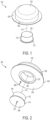
- FIG. 1 illustrates an exemplary drug delivery system 100.
- the drug delivery system 100 can include a drug delivery device 102 and a sensor 104.
- the drug delivery device 102 can be any type of drug delivery device.
- the drug delivery device 102 can deliver any type of drug or therapeutic agent to a user.
- the drug delivery device 102 can store and deliver insulin to a user and can be considered to be a drug delivery device "pump".
- FIG. 1 shows a first view of the drug delivery system 100.
- the sensor 104 can be any type of sensor.
- the sensor 104 can monitor one or more health, biological, biomedical, or medical conditions of a user.
- the sensor can be a continuous glucose monitoring (CGM) sensor.
- CGM continuous glucose monitoring
- the drug delivery device 102 can include a base component 106 and a housing component 108.
- the base 106 can be considered a lip component or portion that extends around and beyond the housing 108.
- the housing 108 can be cylindrically shaped with a circular cross-sectional profile and a tapered top portion but is not so limited.
- the base 106 can also be circular but is not so limited.
- the circular base 106 can have a diameter that is larger than a diameter of the housing 108 such that the base 106 includes an edge or lip portion that extends beyond the outer diameter of the housing 108.
- the drug delivery device 102 can include all components for storing a liquid drug or other therapeutic agent and providing the stored liquid drug or therapeutic agent to a user of one or more doses.
- the CGM sensor 104 can include a base component 110 and a housing component 112.
- the base 110 can include a lip component or portion that extends around and beyond the housing 112.
- the housing 112 can be cylindrically shaped with a circular cross-sectional profile but is not so limited.
- the base 110 can also be circular but is not so limited.
- the circular base 110 can have a diameter that is larger than a diameter of the housing 112 such that the base 110 includes an edge or lip portion that extends beyond the outer diameter of the housing 112.
- the CGM sensor 104 can include all components for monitoring glucose levels of a user.
- the drug delivery device 102 and the CGM sensor 104 can each have any size, shape, or form factor. In general, the drug delivery device 102 and the CGM sensor 104 can each be made to be small and compact with low profile form factors (e.g., as shown in FIG. 1 ) to maximize comfort for a user while remaining inconspicuous.
- the drug delivery system 100 can be a wearable drug delivery system.
- the drug delivery system 100 can be worn directly on the body or skin of a user.
- the CGM sensor 104 can be positioned within a central opening of the drug delivery device 102 (as indicated by indicator 114).
- the base 110 and the housing 112 of the CGM sensor 104 can fit within the central cavity of the drug delivery device 102.
- the drug delivery device 102 can fit over the CGM sensor 104 such that the bottom surfaces of the drug delivery device 102 and the CGM sensor 104 are aligned and/or level (e.g., coplanar). In this way, the drug delivery system 100 can be easily attached to a user and can rest comfortably on the user.
- the arrangement of the drug delivery device 102 and the CGM sensor 104 allows the drug delivery device 102 to be removed and replaced.
- a new drug delivery device 102 can be positioned on top of the CGM sensor 104.
- the CGM sensor 104 can generally have a duration of use that is longer than the duration of use of the drug delivery device 102.
- the CGM sensor 104 can have a first duration of use that can be approximately twelve (12) days.
- a sensing cannula of the CGM sensor 104 can remain fixed in place (e.g., within the body of the user).
- the drug delivery device 102 can have a duration of use that can be approximately three (3) days. During the duration of use of the drug delivery device 102, an infusing cannula of the drug delivery device 102 can remain fixed in place (e.g., within the body of the user). With the drug delivery system 100, the infusion site for a user can be changed each time the drug delivery device 102 is replaced. This is advantageous as an infusion site can become less effective after roughly three (3) days of use.
- the infusion site can be changed.
- the drug delivery device 102 can be replaced several times (e.g., four (4) times) before both the last drug delivery device 102 and the CGM sensor 104 are both removed and replaced together (e.g., at a new site on the body of the user).
- the drug delivery system 100 enables a sensing site for glucose monitoring to be maintained for the entire duration of use of the CGM sensor - which increases the effectiveness of the monitoring or sensing site - while providing the flexibility to adjust the infusion site.
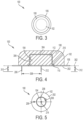
- FIG. 2 illustrates a second view of the drug delivery system 100.
- the drug delivery device 102 can include a bottom surface 202 and an opening or cavity 204.
- the opening 204 can be positioned in a center of the bottom surface 202.
- the opening 204 can be circular but is not so limited. In generally, the opening 204 can be shaped to accommodate the drug delivery device 102 fitting over the CGM sensor 104.
- the bottom surface 202 can also be circular with an inner diameter (e.g., defining a boundary of the outer portion of the opening and an inner portion of the bottom surface 202) and an outer diameter (e.g., defining a boundary of the outer portion of the bottom surface 202).
- a cannula 206 (e.g., an infusion cannula) can extend from the bottom surface 202.
- the cannula 206 can be positioned along any portion of the bottom surface 202 (e.g., offset from a center of the bottom surface 202).
- the CGM sensor 104 can include a bottom surface 208.
- the bottom surface 208 can be circular but is not so limited.
- An outer portion of the base 110 can fit or be positioned within a recess 210 of the base 106 of the drug delivery device 102.
- the recess 210 can be positioned around the opening 204.
- the outer edge of the bottom surface 208 can reside with the recess 210, thereby allowing the bottom surface 202 and the bottom surface 208 to form a substantially flat surface (e.g., to be aligned or coplanar and/or to form a single continuous surface as felt by the user wearing the drug delivery system 100).
- a cannula 212 (e.g., a sensing cannula) can extend from the bottom surface 208.
- the cannula 212 can be positioned along any portion of the bottom surface 208. In various embodiments, the cannula 212 can extend from a center of the bottom surface 208.
- FIG. 3 illustrates an overhead view of the drug delivery system 100.
- the drug delivery device 102 covers the CGM sensor 104 such that the CGM sensor 104 is not visible from an overhead view of the drug delivery system 100.
- An outer portion of the base 106 extends beyond the housing 108. Accordingly, in various embodiments, the width, diameter, and/or perimeter of the base 106 may be larger than the width, diameter, and/or perimeter of the housing 108.
- FIG. 4 illustrates a cross-sectional side view of the drug delivery system 100.
- the CGM sensor 104 is positioned within the opening 204 of the drug delivery device 102.
- the CGM 104 can be positioned within the opening 204 such that the bottom surface 208 of the CGM sensor 104 is aligned with the bottom surface 202 of the drug delivery device 102.
- the bottom surfaces 202 and 208 can be substantially coplanar - e.g., aligned along an axis 302 as shown in FIG. 4 .
- the drug delivery device 102 can cover all outer surfaces of the CGM sensor 104 other than the bottom surface 208 of the CGM sensor 104 - such that, for example, the CGM sensor 104 is encapsulated by the drug delivery device 102 and the body of the user.
- FIG. 4 shows a first clearance or distance (or space or spacing) 304 between a top of the housing 112 and an inner upper surface of the housing 108.
- FIG. 4 shows a second clearance or distance (or space or spacing) 306 between an outer diameter of the housing 112 and a diameter of the opening 204.
- the first and second clearances 304 and 306 can be of any size. In general, the first and second clearances 304 and 306 can be relatively small (e.g., relative to the overall width of the drug delivery system 100) such that the CGM sensor 104 forms a tight fit inside the opening 204.
- an outer portion or lip of the base 110 is positioned within the recess 210 to facilitate the alignment of the bottom surfaces 202 and 208.
- the cannula 214 is shown spaced a distance 308 from the cannula 206.
- the distance 308 can be a minimum distance.
- the drug delivery device 102 or a replacement drug delivery device 102 can be positioned over the CGM sensor 104 in any rotational position relative to the CGM sensor 104
- the cannula 206 can be positioned the distance 308 away from the cannula 212 according to any rotational position (e.g., along any position along a circle having a radius of distance 308; 360 degrees around the site of the cannula 212).
- the cannula 206 can have a depth (e.g., an infusion depth) 310.
- the cannula 212 can have a depth (e.g., a sensing depth) 312.
- the depths 310 and 312 can be the same depths (as shown in FIG. 4 ) but are not so limited.
- the position of the cannula 212 with respect to the body of a user can be considered to be a sensing site.
- the position of the cannula 206 with respect to the body of the user can be considered to be an infusion site.
- the drug delivery device 102 can be positioned over the CGM sensor 104 in any orientation - for example, the infusion site can be spaced the distance 308 from the sensing site at any angular orientation relative to the sensing site. This allows the infusion site provided by the cannula 206 to be rotated or adjusted around the body of the user while the sensing site remains fixed - for example, when the drug delivery device 102 is removed and replaced with a subsequent or next drug delivery device 102. When removing the drug delivery device 102, the attachment of the CGM sensor 104 can be undisturbed. The next drug delivery device 102 can then be placed over and fitted on top of the CGM sensor 104 in the same manner the original drug delivery device 102 was placed over the CGM sensor 104. Again, this allows the CGM sensor to operate using a sensing site that remains fixed over the duration of use of the CGM sensor while the infusion sites associated with one or more corresponding drug delivery devices 102 can be changed with each new drug delivery device 102.
- FIG. 5 illustrates an underside view of the drug delivery system 100 (e.g., a view of the bottom of the drug delivery system 100).
- the CGM sensor 104 is positioned within the opening 204 with the clearance 306 separating the CGM sensor 104 from the drug delivery device 102.
- the cannula 206 is shown separated by the distance 308 from the cannula 212.
- the bottom surface 202 and/or the bottom surface 208 can include an adhesive to facilitate coupling to the body (e.g., skin) of a user. Any portion of the bottom surface 202 can include an adhesive. Similarly, any portion of the bottom surface 208 can include an adhesive.
- the adhesive on the bottom surface 208 can be the same adhesive on the bottom surface 202 or can be a different adhesive.
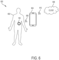
- FIG. 6 illustrates an exemplary operating environment 600 of the drug delivery system 100.
- the operating environment can include a user or patient 602, the drug delivery system 100, a controller device 604, and a remote or cloud computing component 606.
- the user 602 can be a user of the drug delivery system 100.
- the controller device 604 can be a handheld computing device including a dedicated (e.g., customized) controller or a smartphone for controlling operation of the drug delivery system 100.
- the controller device 604 can be a tablet or a desktop computer.
- the controller device 604 can be any computing device, including a mobile computing device, and can be a commercial off the shelf (COTS) computing device or a customized computing device.
- COTS commercial off the shelf
- the controller device 604 can be used by the user 602 to manage operation of the drug delivery system 100 and to visually observe performance information related to operation of the drug delivery system 100.
- the cloud component 606 can represent a remote computing platform.
- the cloud component 606 can monitor operation of the drug delivery system 100 through connectivity with the controller device 604.
- the cloud component 606 can store and analyze data related to operation of the drug delivery system 100 (e.g., as determined or adjusted by the controller device 604).
- the cloud component 606 can be connected to one or more remote computing devices to facilitate viewing or manipulation of any stored operational data. For example, a mobile device of a remote caregiver can receive operational data stored by the cloud component 606 for viewing and/or manipulation.
- a communications link 608 can provide connectivity between the drug delivery system 100 and the controller device 604 and a communications link 610 can provide connectivity between the controller device 604 and the cloud component 606.
- the communication links 608 and 610 can be bi-direction communication links and can include wired, wireless, optical, and/or infrared communication links.
- the communication links 608 and 610 can operate according to any known communications standard or protocol over any type of communications medium or link.
- a computing device coupled to the cloud component 606 can control operation of the drug delivery system 100 (e.g., by a caregiver during an emergency).
- the CGM sensor 104 can monitor glucose levels and store data indicative of the same. This data can be provided to the drug delivery device 102 to adjust operation of the drug delivery device 102. In various embodiments, data from the CGM sensor 104 can be passed along to the controller device 604 and/or the cloud component 606 by the drug delivery device 102.
- the CGM sensor and the drug delivery device 102 can be connected over a wired, wireless, optical, and or infrared communication link.
- the communication link coupling the CGM sensor 104 to the drug delivery device 102 can operate according to any known communications standard or protocol over any type of communications medium or link.
- the drug delivery device 102 can communicate with the controller device 604 over Bluetooth Low Energy (BLE).
- BLE Bluetooth Low Energy
- the CGM sensor 104 can communicate with the drug delivery device 102 over Near-field communication (NFC), a radio-frequency (RF) communication standard, or BLE.
- NFC Near-field communication
- RF radio-frequency
- the drug delivery device 102 can include more resources (e.g., power resources and/or transmission signal strength) for providing more reliable communications with the controller device 604 compared to the resources (e.g., power resources and/or transmission signal strength) of the CGM sensor 104 for communicating with the drug delivery device 102.
- the conventional CGM sensors For conventional CGM sensors that communicate with separate (e.g., de-coupled) conventional drug delivery devices, the conventional CGM sensors often are unable to relay stored data to a conventional controller device - e.g., because the communication protocol and/or transmission levels of the conventional CGM sensors are often too low such that the conventional controller devices are often out of range of the conventional CGM sensors.
- many conventional CGM sensors cannot provide their monitored glucose data to a conventional controller device such that the data can be used to more efficiently operate a conventional drug delivery device.
- the data collected by the conventional CGM sensor is lost or unused.
- a user of such a conventional CGM sensor must awkwardly wave her conventional controller device over the conventional CGM sensor repeatedly to ensure reception of the transmitted data. "Picking up" the stored glucose data from the conventional CGM sensor in this manner is often required during inconvenient times for the user, making the process cumbersome and undesirable.
- the drug delivery system 100 provides improved communication capabilities by closely locating (e.g., co-locating) the CGM sensor 104 with the drug delivery device 102. In doing so, even if the CGM sensor 104 uses a traditionally low power method of communication (e.g., a low power wireless standard), the drug delivery device 102 can detect any data transmission from the CGM sensor 104 due to the close proximity of the CGM sensor 104 and the drug delivery device 102. As a result, data from the CGM sensor 104 can be relayed to the controller device 604 (and subsequently on to the cloud component 606) by the drug delivery device 102. In turn, the drug delivery device 102 can be operated more efficiently to better manage the health of the user 602.
- a traditionally low power method of communication e.g., a low power wireless standard
- FIG. 7 illustrates an exemplary rotation of infusion sites for a fixed position of a sensing site for the drug delivery system 100 using, for example, multiple replacement drug delivery devices 102.
- FIG. 7 shows an underside or bottom view of the drug delivery system 100.
- an infusion site availability circle 702 surrounds the cannula 212 (or the site of the cannula 212 or sensing site).
- the circle 702 can be centered about the cannula 212 and can have a radius equal to the distance 308.
- the circle 702 can represent possible locations of the cannula 206 (or the site of the cannula 206 of the infusion site).
- the cannula 206 can be positioned anywhere along the circle 702.
- the cannula 206 is shown positioned along the circle 702.
- the CGM sensor 104 can be worn by a patient for twelve (12) days. Accordingly, the cannula 212 is positioned as shown for the entirety of the twelve (12) days (e.g., the cannula 212 can be located as shown for the entire duration of use of the CGM sensor 104).
- the drug delivery device 102 can be used for three (3) days and then replaced with another drug delivery device 102.
- the position of the cannula 206 can be changed or adjusted for each new drug delivery device 102. In particular, the position of the cannula 206 can be rotated along the circle 702.
- FIG. 7 shows an exemplary rotation of the infusion site provided by rotating the cannula 206 associated with each drug delivery device 102 used with the CGM sensor 104.
- site 704 can represent a first or initial site for cannula 206 (e.g., for days 1-3).
- the first site 704 can be positioned along a first central axis 714.
- the cannula 212 and the first site 704 can both be positioned along the central axis 714 separated by the distance 308.
- Site 706 can represent a second site for the cannula 206 (e.g., for days 4-6).
- the second site 706 can represent the position of the cannula 206 when a second drug delivery device 102 replaces the first drug delivery device 102 that is associated with the first site 704.
- the second site 706 can also be positioned along the axis 714.
- the second site 706 can be positioned 180 degrees away from the first site 704 along the circle 702 relative to the fixed location of the cannula 212.
- Site 708 can represent a third site for the cannula 206 (e.g., for days 7-9).
- the third site 708 can represent the position of the cannula 206 when a third drug delivery device 102 replaces the second drug delivery device 102 that is associated with the second site 706.
- the third site 708 can be positioned along a second central axis 712.
- the second central axis 712 can be perpendicular to the first central axis 714.
- the third site 708 can be positioned 90 degrees away from the second site 706 along the circle 702 relative to the fixed location of the cannula 212.
- Site 710 can represent a fourth site for the cannula 206 (e.g., for days 10-12).
- the fourth site 710 can represent the position of the cannula 206 when a fourth drug delivery device 102 replaces the third drug delivery device 102 that is associated with the third site 708.
- the fourth site 710 can be positioned along the first axis 714.
- the fourth site 710 can be positioned 180 degrees away from the third site 708 along the circle 702 relative to the fixed location of the cannula 212.
- FIG. 7 shows an exemplary rotation of the infusion site using the cannula 206.
- any rotation of the cannula 206 along the circle 702 can be used with the position of the infusion site changing with each new drug delivery device 102.
- a new sensing site for the cannula 212 can be chosen on the user.
- infusion sites relative to the new sensing site e.g., spaced a distance 308 away
- a sensor and drug delivery device can have different durations of use.
- a sensor e.g., a CGM sensor
- a drug delivery device e.g., a wearable drug delivery device such as an insulin pump
- a CGM may have a duration of use of 12 days or longer while a wearable drug delivery device may have a duration of use of 3 days.
- a drug delivery system incorporating a CGM sensor and a wearable drug delivery device that relies on the CGM sensor for effective operation is to account for the different durations of use in accordance with the techniques disclosed herein.
- a sensor e.g., a CGM sensor
- a CGM sensor can be sterilized in a first manner that may not be compatible with a wearable drug delivery device.
- a CGM sensor may be effectively sterilized using gamma radiation.
- a wearable drug delivery device which may include electronics
- sterilization by gamma radiation may not be possible.
- Ethylene Oxide (EO) sterilization may be used, which is not compatible with the CGM sensor.
- EO Ethylene Oxide
- a drug delivery system incorporating a CGM sensor and a wearable drug delivery device that relies on the CGM sensor for effective operation is to account for the different sterilization methods for the two components.
- a CGM sensor may need to be coupled to a use for a period of time before the site properly provides proper sensor measurements. That is, a CGM sensor may need to be in place for roughly a day or so before measurements made by the CGM sensor can be considered accurate and trustworthy.
- the infusion site associated with a wearable drug delivery device may only be useable for a few days (e.g., at most 3 days) before the site becomes unusable (e.g., due to the user's body resisting the infusion site after a few days). Accordingly, a drug delivery system incorporating a CGM sensor and a wearable drug delivery device that relies on the CGM sensor for effective operation is to account for these different use restrictions.
- the disclosed systems, devices, methods, and techniques disclosed herein can account for and accommodate these competing characteristics of a CGM sensor and wearable drug delivery device.
- FIG. 8 illustrates an overhead view of a portion of a second exemplary drug delivery system 800.
- the drug delivery system 800 can be alternative implementation of the drug delivery system 100.
- FIG. 8 shows an adhesive pad 802 and an incorporated sensor 804 (e.g., a CGM sensor).
- the CGM sensor 804 can be directly coupled to the adhesive pad 802. This arrangement allows the CGM sensor 804 and adhesive pad to be sterilized according to a first sterilization technique, such as gamma radiation.
- the cGM sensor 804 can be shown in phantom to show a possible position of the CGM sensor 804 and to reflect that it can be positioned on top of the adhesive pad 802 or can be positioned within an interior of the adhesive pad 802.
- An outline 806 indicates where a drug delivery device (e.g., an insulin pump) can be attached to the adhesive pad 802 as described further herein.
- the drug delivery device can be separately attached to the adhesive pad 802 having the incorporated CGM sensor 804. In this way, the drug delivery device can be sterilized according to a separate technique more suitable to the drug delivery device and then later coupled to the CGM sensor 804.
- the drug delivery device can be attached to the adhesive pad by a variety of techniques including using snaps or connectors 808. Any number of snaps and/or connectors 808 can be used.
- Indicator 810 shows a position of a sensing site associated with the CGM sensor 804. That is, a sensing needle (or needles) can extend from the underside of the CGM sensor 804 at the site 810.
- the site 810 is shown in phantom to indicate that the site is position on the underside of the CGM sensor 804 at an opening of the adhesive pad 802.
- the adhesive pad 802 can be positioned over an entirety of the underside of the CGM sensor 804 other than at the opening to accommodate the site 810.
- the adhesive pad 802 and the incorporated CGM sensor 804 can be attached to a user.
- the adhesive pad 802 and the incorporated CGM sensor 804 can be coupled to a user for a first period of time before a drug delivery device is coupled to the adhesive pad 802 and the incorporated CGM sensor 804 (or before a coupled drug delivery device is activated).
- the sensing site (or sites) associated with the adhesive pad 802 and the incorporated CGM sensor 804 can operate over the first period of time to reach a steady state (e.g., allowing the sensing sites to become reliable).
- the drug delivery device can be coupled over the CGM sensor 804 and can be coupled to the adhesive pad 802 by the connectors 808.
- the connectors 808 can be mechanical and can be, for example, latches or other devices providing a press fit.
- the adhesive pad 802 can include a first infusion site or opening 812 and a second infusion site or opening 814.
- the drug delivery device when attached to the adhesive pad 802 can use either the firs tor second openings 812 and 814 for deploying an infusion needle or cannula.
- an initial drug delivery device can be removed and replaced with a second drug delivery device.
- the first drug delivery device can use the first opening 812 for the infusion site.
- the second drug delivery device can use the second opening 814 for the infusion site. In this way, the infusion site can be rotated and changed over the duration of use of the adhesive pad 802 with the incorporated CGM sensor 804.
- the openings 812 and 814 can be holes or openings within the adhesive pad 802.
- the adhesive pad 802 is no limited to the shape depicted. In various embodiments, the adhesive pad 802 can have any shape including round or oval. In various embodiments, the adhesive pad 802 can have multiple openings to facilitate rotation of the infusion site (e.g., more than the two openings 812 and 814). In various embodiments, the drug delivery device can be rotated in any manner with respect to the sensing site opening 810.
- the drug delivery system 800 can be used to initially attach the adhesive pad 802 with the incorporated CGM sensor 804 to a user.
- the CGM sensor 804 can be configured for operation and can be operated to have one or more sensing sites. After a period of time has elapsed, during which operation of the CGM sensor 804 reaches a steady state (e.g., at a time when measurements made by the CGM sensor 04 are accurate and/or reliable), the drug delivery device can be attached to the adhesive pad 802 (and positioned over top of the CGM sensor 804).
- the drug delivery device can use on of the two openings 812 and 814 for the first infusion site.
- the drug delivery device After the drug delivery device has been used for a few days, it can be removed/de-coupled from the adhesive pad 802 and replaced with another drug delivery device.
- the second drug delivery device can use one of the openings 812 and 814 not used by the first drug delivery device. This process can be repeated until the duration of use of the CGM sensor 804 has been reached with each drug delivery device using a different infusion site from the prior drug delivery device.
- FIG. 9 illustrates a front view of the drug delivery system 800.
- the drug delivery system 800 shows the adhesive pad 802 having the incorporated CGM sensor 804 positioned over the adhesive pad 802.
- a drug delivery device 902 is positioned over the CGM sensor 804.
- a first cannula 904 is positioned through one of the openings 812 and 814 to provide an infusion site.
- the first cannula 904 can be coupled to the drug delivery device 902.
- a second cannula 906 and a third cannula 908 can be coupled to the CGM sensor 804 and can provide first and second sensing sites, respectively.
- a single sensing site can be provided and/or more than two sensing sites and cannulas can be used.
- the sensing sites provided by the cannulas 906 and 908 are spaced apart from the infusion site provided by the cannula 904.
- the drug delivery system 800 and any constituent component thereof can have any size shape, and/or form factor and is not limited to the exemplary shapes shown in FIG. 9 (and/or FIGs. 8 and 10-13 ).
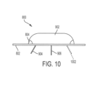
- FIG. 10 illustrates a side view of the drug delivery system 800.
- the drug delivery device 902 is positioned over the CGM sensor 804 that is incorporated with the adhesive pad 802.
- the cannula 906 is shown positioned in an approximate middle of the drug delivery system 800.
- the cannula 904 is shown positioned at a first end of the drug delivery system 800 - for example, using the opening 812.
- a second cannula 1002 is shown in phantom to represent the location of a second infusion site that can be used through opening 814 when the drug delivery device 902 is replaced.
- FIG. 11 illustrates an isometric view of the drug delivery system 800. As shown, the drug delivery device 802 is positioned over the CGM sensor 804 incorporated into the adhesive pad 802.
- FIG. 12 illustrates a CGM sensor configuration component or module 1202.
- the CGM sensor configuration module 1202 can be initially coupled to the CGM sensor 804 when provided to the user or can be later attached to the CGM sensor 804 by the user (e.g., using the connectors 808).
- the CGM sensor configuration module 1202 can be an entirely mechanical based system such that it can be sterilized in the same manner as the adhesive pad 802 and the CGM sensor 804.
- the CGM sensor configuration module 1202 can include electrical and/or electronical components such that it can undergo a different sterilization technique from the adhesive pad 802 and the CGM sensor 804. Under such a scenario, the CGM sensor configuration module 1202 can be coupled to the adhesive pad 802 and the CGM sensor 804 at a later time.
- the CGM sensor configuration module 1202 can be used to configure operation of the CGM sensor 804. After configuring the CGM sensor 804, the CGM sensor configuration module 1202 can be removed and/or detached from the adhesive pad 802 and/or the CGM sensor 804 and replaced with the drug delivery device 902.
- the CGM sensor configuration module 1202 can include a user interface component 1204,
- the user interface component 1204 can comprise a button and/or a knob.
- the user interface component 1204 can be used to activate the CGM sensor 804 - for example, by the user turning a knob and/or pressing a button.
- the user interface component 1204 can be used to set a number of sensing sites to be used (e.g., a number of sensing cannulas to deploy), set a depth of sensing (e.g., set a depth for each sensing cannula), and/or to trigger release of the cannulas.
- the CGM sensor 804 can begin operation.
- the CGM sensor configuration module 1202 After the CGM sensor configuration module 1202 has been used to configure operation of the CGM sensor 804, the CGM sensor configuration module 1202 can be removed from the adhesive pad 802. After the CGM sensor 804 has been operating for an appropriate amount of time, the drug delivery device 902 can be coupled to the adhesive pad 802 and positioned over the CGM sensor 804. The drug delivery device 902 can be coupled in a manner to enable glucose measurements or other data collected or derived by the CGM sensor 804 to be passed to the drug delivery device 902 for use in controlling operation of the drug delivery device 902 (e.g., adjusting a dose of a medicine provided to the user).
- FIG. 13 illustrates a side view of the CGM sensor configuration module 1202 depicted in FIG. 12 .
- the CGM sensor configuration module 1202 is positioned over the CGM sensor 804.
- the cannulas 906 and 908 have been deployed indicating the CGM sensor 804 has been configured for operation. Accordingly, the CGM sensor configuration module 1202 can be removed and replaced with the drug delivery device 902.
- the adhesive pad 802 can have any number of holes positioned on any portion of the adhesive pad 802. In various embodiments, the adhesive pad 802 can have four holes positioned a same distance from a center of a bottom surface of the adhesive pad 802. The four holes can be positioned along a circle that surrounds the center of the bottom surface of the adhesive pad 802, with the center representing a position from which the one or more sensing cannulas of the CGM sensor 804 extend.
- the CGM sensor 804 can be incorporated into the adhesive pad 802 to form a single combined component.
- the CGM sensor 804 can only include mechanical components and does not contain any electrical components.
- the drug delivery device 902 can include mechanical and/or electrical components.
- the CGM sensor configuration module 1202 can include mechanical and/or electrical components. This can allow the drug delivery device 902 and the CGM sensor configuration module 1202 to undergo a sterilization process that is different from a sterilization process that the adhesive pad 802 and incorporated CGM sensor 804 can undergo.
- the CGM sensor configuration module 1202 can include only mechanical components, allow the CGM sensor configuration module 1202, the adhesive pad 802, and the incorporated CGM sensor 804 to all undergo the same sterilization process and to be provided to a user connected together as one assembly. Then, once the user configures operation of the CGM sensor 104, the user can snap off the CGM sensor configuration module 1202 and replace it with the drug delivery device 902.
- FIG. 14 illustrates a third exemplary drug delivery system 1400.
- the drug delivery system 1400 can be alternative implementation of the drug delivery system 100.
- the drug delivery system 1400 can include a sensor 1402.
- the sensor 1402 can be a CGM sensor.
- FIG. 14 shows a view of the bottom or underside of the sensor 1402.
- the CGM sensor 1402 can include an adhesive pad 1404, a first electrode 1406, and a second electrode 1408.
- the CGM sensor 1402 can be circularly-shaped but is not so limited.
- the adhesive pad 1404 can be positioned toward a periphery or outer portion of the bottom surface of the CGM sensor 1402.
- the adhesive pad 1404 can be arranged in a first circle.
- the first electrode 1406 can be positioned toward a middle portion of the bottom surface of the CGM sensor 1402.
- the first electrode 1406 can be arranged in a second circle (e.g., concentric with the first circle of the adhesive pad 1404 and smaller).
- the second electrode 1408 can be positioned toward a central portion of the bottom surface of the CGM sensor 1402.
- the second electrode 1408 can be arranged in a third circle (e.g., concentric with the first circle of the adhesive pad 1404 and second circle of the first electrode 1406 and smaller).
- the CGM sensor 1402 can include a sensing cannula.
- the sensing cannula can extend from any portion of the bottom surface of the CGM sensor 1402 (e.g., from a center of the bottom surface).
- the CGM sensor 1402 can be coupled to a user for multiple days - for example, for a period of time of 10 days or more.
- FIG. 14 further shows a drug delivery device 1410.
- the drug delivery device 1410 can be an alternative implementation of the drug delivery device 102.
- FIG. 14 can show a top view of the drug delivery device 1410.
- the drug delivery device 1410 can include an adhesive pad 1412.
- the adhesive pad 1412 can be coupled to a bottom surface of the drug delivery device 1410.
- the drug delivery device 1410 can be attached to a user by the adhesive pad 1412 and intended to be used for a duration of time that is less than a duration of use of the CGM sensor 1402.
- the duration of use of the drug delivery device 1410 can be approximately 3 to 4 days, after which the drug delivery device 1410 can be removed from the user (e.g., replaced by a next or subsequent drug delivery device 1410).
- the drug delivery device 1410 can include an opening 1414.
- the CGM sensor 1402 can be positioned into the opening 1414. When positioned in the opening 1414, the CGM sensor 1402 can be coupled to the body of the user (e.g., the adhesive pad 1404 and the first and second electrodes 1406 and 1408 can contact the body of the user). Further, the CGM sensor 1402 can be electrically coupled to the drug delivery device 1410 when positioned in the opening 1414 to allow data from the CGM sensor 1402 to be provided to the drug delivery device 1410.
- the drug delivery device 1410 can include an infusion cannula.
- Indicator 1416 shows a position or site of the infusion cannula (in phantom to indicate the site 1416 extends from the bottom surface of the drug delivery device 1410).
- the CGM sensor 1402 can first be coupled to the body of a user. The drug delivery device 1410 can then be positioned over the CGM sensor 1402 such that the CGM sensor 1402 is positioned within the opening 1414. The drug delivery device 1410 can be positioned in any orientation relative to the CGM sensor 1402 such that the infusion site 1416 can be at any rotational position from a center of the CGM sensor 1402.
- the first drug delivery device 1410 When the first drug delivery device 1410 has been used for its duration of use, it can be detached from the user without disrupting the position of the CGM sensor 1402. A second or subsequent drug delivery device 1410 can then be positioned over the CGM sensor 1402 and attached to the user. The second drug delivery device 1410 can be rotated relative to the former position of the first drug delivery device 1410 such that the infusion sites 1412 differ (e.g., vary by at least 90 degrees relative to a center of the CGM sensor 1402).
- the drug delivery system 1400 enables an unlimited number of orientations of the drug delivery device 1410 relative to the CGM sensor 1402 and therefore an unlimited number of possible infusion sites 1416 that can be changed over the course of use of the CGM sensor 1402 as multiple drug delivery device 1410 are used with the same CGM sensor 1402.
- the CGM sensor 1402 can include electronic components.
- the drug delivery device 1410 can include only mechanical components.
- the CGM sensor 1402 can include a controller component to control operation of the drug delivery device 1410.
- Each of the drug delivery devices described herein can be a wearable or on-body drug delivery device or pump, such as an OmniPod (Insulet Corporation, Billerica, MA, USA) device and/or any of the drug delivery devices described in U.S. Patent Nos. 7,303,549 ; 7,144,384 ; 7,137,964 ; 6,960,192 ; 6,740,059 ; 6,699,218 ; 9,402,950 ; 7,771,412 ; 7,029,455 ; 6,740,05 ; and 6,656,159 .
- OmniPod Insulet Corporation, Billerica, MA, USA
- each of the drug delivery devices disclosed herein can include one or more reservoirs or chambers configured to store a liquid drug and a drug delivery mechanism or component for extracting (e.g., pumping) the liquid drug out of the reservoir for delivery to a user.
- each of the drug delivery devices disclosed herein can include one or more infusion cannulas for provided the stored liquid drug to the user over one or more doses and/or based on data provided by any of the sensors disclosed herein.
- the sensor can be coupled to the drug delivery device in any manner (e.g., over a wired or wireless link) to allow the bidirectional flow of any data (e.g., control data, user data, etc.).
Description
- Embodiments generally relate to medication delivery. More particularly, embodiments relate to drug delivery systems that rely on associated sensors.
- Many conventional drug delivery systems include a drug delivery device and an associated sensor. The sensor can determine and store data related to a user of the drug delivery device. The drug delivery device can then be operated based on the data related to the user. Often, the sensor and the drug delivery device are controlled by a remote device. Conventional sensors generally operate at low power levels to conserve resources. As a result of low transmission power levels, many conventional sensors cannot always relay the stored data to the remote control to ensure efficient operation, of the drug delivery device. Further, many conventional drug delivery systems that combine or collocate the sensor and the drug delivery device fail to account for the different, durations of use of the sensor and the drug delivery device. As a result, either the sensor is prematurely replaced or the infusion site of the drug delivery device is not spaced far enough away or changed frequently enough in relation to the sensing site of the cannula.
- Conventional drug delivery systems using a sensor are e.g. known from
US 2011/0213306 A1 ,US 2012/0184909 A1 andUS 5,800420 . - There is a need for a drug delivery system that includes a drug delivery device and associated sensor that ensures data from the sensor can be provided to a remote controller device and improves management of the infusion site in view of the sensing site.
-
- FIG. 1
- illustrates an exemplary drug delivery system.
- FIG. 2
- illustrates a second view of the drug delivery system depicted in
FIG. 1 . - FIG. 3
- illustrates an overhead view of the drug delivery system depicted in
FIG. 1 . - FIG. 4
- illustrates a cross-sectional side view of the drug delivery system depicted in
FIG. 1 . - FIG. 5
- illustrates an underside view of the drug delivery system depicted in
FIG. 1 , - FIG. 6
- illustrates an exemplary operating environment of the drug delivery system depicted in
FIG. 1 . - FIG. 7
- illustrates an exemplary rotation of infusion sites for a fixed position of a sensing site for the drug delivery system depicted in
FIG. 1 . - FIG. 8
- illustrates an overhead view of a second exemplary drug delivery system.
- FIG. 9
- illustrates a front view of the drug delivery system depicted in
FIG. 8 . - FIG. 10
- illustrates a side view of the drug delivery system depicted in
FIG. 8 . - FIG. 11
- illustrates an isometric view of the drug delivery system depicted in
FIG. 8 . - FIG. 12
- illustrates a sensor configuration module of the drug delivery system depicted in
FIG. 8 . - FIG. 13
- illustrates a side view of the sensor configuration module depicted in
FIG. 12 . - FIG. 14
- illustrates a third exemplary drug delivery system.
- This disclosure presents various systems, components, and methods related to a drug delivery system. Each of the systems, components, and methods disclosed herein provides one or more advantages over conventional systems, components, and methods.
- Various embodiments include a drug delivery system having a drug delivery device and an associated sensor. The sensor can be associated with a sensing site on the body of a user. The drug delivery device can be positioned over the sensor in any rotational position and can be associated with an infusion site on the body of the user. The close positioning of the sensor and the drug delivery device allows data from the sensor to be relayed to the drug delivery device and then on to a remote control device. Further, the drug delivery device can be replaced at the end of its duration of use, which is shorter than the duration of use of the sensor, without disturbing the sensor. One or more subsequent drug delivery devices can be used with the sensor while allowing each corresponding infusion site to be changed, thereby providing more efficient operation of the drug delivery system. Other embodiments are disclosed and described.
-
FIG. 1 illustrates an exemplarydrug delivery system 100. Thedrug delivery system 100 can include adrug delivery device 102 and asensor 104. Thedrug delivery device 102 can be any type of drug delivery device. Thedrug delivery device 102 can deliver any type of drug or therapeutic agent to a user. In various embodiments, thedrug delivery device 102 can store and deliver insulin to a user and can be considered to be a drug delivery device "pump".FIG. 1 shows a first view of thedrug delivery system 100. - The
sensor 104 can be any type of sensor. Thesensor 104 can monitor one or more health, biological, biomedical, or medical conditions of a user. In various embodiments, the sensor can be a continuous glucose monitoring (CGM) sensor. - As shown in
FIG. 1 , thedrug delivery device 102 can include abase component 106 and ahousing component 108. Thebase 106 can be considered a lip component or portion that extends around and beyond thehousing 108. Thehousing 108 can be cylindrically shaped with a circular cross-sectional profile and a tapered top portion but is not so limited. The base 106 can also be circular but is not so limited. In various embodiments, thecircular base 106 can have a diameter that is larger than a diameter of thehousing 108 such that thebase 106 includes an edge or lip portion that extends beyond the outer diameter of thehousing 108. Thedrug delivery device 102 can include all components for storing a liquid drug or other therapeutic agent and providing the stored liquid drug or therapeutic agent to a user of one or more doses. - The
CGM sensor 104 can include abase component 110 and ahousing component 112. The base 110 can include a lip component or portion that extends around and beyond thehousing 112. Thehousing 112 can be cylindrically shaped with a circular cross-sectional profile but is not so limited. The base 110 can also be circular but is not so limited. In various embodiments, thecircular base 110 can have a diameter that is larger than a diameter of thehousing 112 such that thebase 110 includes an edge or lip portion that extends beyond the outer diameter of thehousing 112. TheCGM sensor 104 can include all components for monitoring glucose levels of a user. Thedrug delivery device 102 and theCGM sensor 104 can each have any size, shape, or form factor. In general, thedrug delivery device 102 and theCGM sensor 104 can each be made to be small and compact with low profile form factors (e.g., as shown inFIG. 1 ) to maximize comfort for a user while remaining inconspicuous. - In various embodiments, the
drug delivery system 100 can be a wearable drug delivery system. For example, thedrug delivery system 100 can be worn directly on the body or skin of a user. In various embodiments, theCGM sensor 104 can be positioned within a central opening of the drug delivery device 102 (as indicated by indicator 114). In such embodiments, thebase 110 and thehousing 112 of theCGM sensor 104 can fit within the central cavity of thedrug delivery device 102. Thedrug delivery device 102 can fit over theCGM sensor 104 such that the bottom surfaces of thedrug delivery device 102 and theCGM sensor 104 are aligned and/or level (e.g., coplanar). In this way, thedrug delivery system 100 can be easily attached to a user and can rest comfortably on the user. - In various embodiments, the arrangement of the
drug delivery device 102 and theCGM sensor 104 allows thedrug delivery device 102 to be removed and replaced. When replacing thedrug delivery device 102, a newdrug delivery device 102 can be positioned on top of theCGM sensor 104. TheCGM sensor 104 can generally have a duration of use that is longer than the duration of use of thedrug delivery device 102. In various embodiments, theCGM sensor 104 can have a first duration of use that can be approximately twelve (12) days. During the duration of use of theCGM sensor 104, a sensing cannula of theCGM sensor 104 can remain fixed in place (e.g., within the body of the user). - In various embodiments, the
drug delivery device 102 can have a duration of use that can be approximately three (3) days. During the duration of use of thedrug delivery device 102, an infusing cannula of thedrug delivery device 102 can remain fixed in place (e.g., within the body of the user). With thedrug delivery system 100, the infusion site for a user can be changed each time thedrug delivery device 102 is replaced. This is advantageous as an infusion site can become less effective after roughly three (3) days of use. - Accordingly, when a first
drug delivery device 102 is removed and replace with a seconddrug delivery device 102, the infusion site can be changed. Thedrug delivery device 102 can be replaced several times (e.g., four (4) times) before both the lastdrug delivery device 102 and theCGM sensor 104 are both removed and replaced together (e.g., at a new site on the body of the user). In this way, thedrug delivery system 100 enables a sensing site for glucose monitoring to be maintained for the entire duration of use of the CGM sensor - which increases the effectiveness of the monitoring or sensing site - while providing the flexibility to adjust the infusion site. -
FIG. 2 illustrates a second view of thedrug delivery system 100. An underside of thedrug delivery system 100 is shown inFIG. 2 . As shown, thedrug delivery device 102 can include abottom surface 202 and an opening orcavity 204. Theopening 204 can be positioned in a center of thebottom surface 202. Theopening 204 can be circular but is not so limited. In generally, theopening 204 can be shaped to accommodate thedrug delivery device 102 fitting over theCGM sensor 104. Thebottom surface 202 can also be circular with an inner diameter (e.g., defining a boundary of the outer portion of the opening and an inner portion of the bottom surface 202) and an outer diameter (e.g., defining a boundary of the outer portion of the bottom surface 202). A cannula 206 (e.g., an infusion cannula) can extend from thebottom surface 202. Thecannula 206 can be positioned along any portion of the bottom surface 202 (e.g., offset from a center of the bottom surface 202). - As further shown in
FIG. 2 , theCGM sensor 104 can include abottom surface 208. Thebottom surface 208 can be circular but is not so limited. An outer portion of the base 110 can fit or be positioned within arecess 210 of thebase 106 of thedrug delivery device 102. Therecess 210 can be positioned around theopening 204. When theCGM sensor 104 is positioned within theopening 204, the outer edge of thebottom surface 208 can reside with therecess 210, thereby allowing thebottom surface 202 and thebottom surface 208 to form a substantially flat surface (e.g., to be aligned or coplanar and/or to form a single continuous surface as felt by the user wearing the drug delivery system 100). - A cannula 212 (e.g., a sensing cannula) can extend from the
bottom surface 208. Thecannula 212 can be positioned along any portion of thebottom surface 208. In various embodiments, thecannula 212 can extend from a center of thebottom surface 208. -
FIG. 3 illustrates an overhead view of thedrug delivery system 100. As shown, thedrug delivery device 102 covers theCGM sensor 104 such that theCGM sensor 104 is not visible from an overhead view of thedrug delivery system 100. An outer portion of thebase 106 extends beyond thehousing 108. Accordingly, in various embodiments, the width, diameter, and/or perimeter of the base 106 may be larger than the width, diameter, and/or perimeter of thehousing 108. -
FIG. 4 illustrates a cross-sectional side view of thedrug delivery system 100. As shown, theCGM sensor 104 is positioned within theopening 204 of thedrug delivery device 102. TheCGM 104 can be positioned within theopening 204 such that thebottom surface 208 of theCGM sensor 104 is aligned with thebottom surface 202 of thedrug delivery device 102. In various embodiments, the bottom surfaces 202 and 208 can be substantially coplanar - e.g., aligned along anaxis 302 as shown inFIG. 4 . As shown, in various embodiments, thedrug delivery device 102 can cover all outer surfaces of theCGM sensor 104 other than thebottom surface 208 of the CGM sensor 104 - such that, for example, theCGM sensor 104 is encapsulated by thedrug delivery device 102 and the body of the user. -
FIG. 4 shows a first clearance or distance (or space or spacing) 304 between a top of thehousing 112 and an inner upper surface of thehousing 108.FIG. 4 shows a second clearance or distance (or space or spacing) 306 between an outer diameter of thehousing 112 and a diameter of theopening 204. The first andsecond clearances second clearances CGM sensor 104 forms a tight fit inside theopening 204. - As further shown in
FIG. 4 , an outer portion or lip of thebase 110 is positioned within therecess 210 to facilitate the alignment of the bottom surfaces 202 and 208. Thecannula 214 is shown spaced adistance 308 from thecannula 206. Thedistance 308 can be a minimum distance. As the drug delivery device 102 (or a replacement drug delivery device 102) can be positioned over theCGM sensor 104 in any rotational position relative to theCGM sensor 104, thecannula 206 can be positioned thedistance 308 away from thecannula 212 according to any rotational position (e.g., along any position along a circle having a radius ofdistance 308; 360 degrees around the site of the cannula 212). - The
cannula 206 can have a depth (e.g., an infusion depth) 310. Similarly, thecannula 212 can have a depth (e.g., a sensing depth) 312. Thedepths FIG. 4 ) but are not so limited. The position of thecannula 212 with respect to the body of a user can be considered to be a sensing site. The position of thecannula 206 with respect to the body of the user can be considered to be an infusion site. - In various embodiments, the
drug delivery device 102 can be positioned over theCGM sensor 104 in any orientation - for example, the infusion site can be spaced thedistance 308 from the sensing site at any angular orientation relative to the sensing site. This allows the infusion site provided by thecannula 206 to be rotated or adjusted around the body of the user while the sensing site remains fixed - for example, when thedrug delivery device 102 is removed and replaced with a subsequent or nextdrug delivery device 102. When removing thedrug delivery device 102, the attachment of theCGM sensor 104 can be undisturbed. The nextdrug delivery device 102 can then be placed over and fitted on top of theCGM sensor 104 in the same manner the originaldrug delivery device 102 was placed over theCGM sensor 104. Again, this allows the CGM sensor to operate using a sensing site that remains fixed over the duration of use of the CGM sensor while the infusion sites associated with one or more correspondingdrug delivery devices 102 can be changed with each newdrug delivery device 102. -
FIG. 5 illustrates an underside view of the drug delivery system 100 (e.g., a view of the bottom of the drug delivery system 100). As shown, theCGM sensor 104 is positioned within theopening 204 with theclearance 306 separating theCGM sensor 104 from thedrug delivery device 102. Thecannula 206 is shown separated by thedistance 308 from thecannula 212. Thebottom surface 202 and/or thebottom surface 208 can include an adhesive to facilitate coupling to the body (e.g., skin) of a user. Any portion of thebottom surface 202 can include an adhesive. Similarly, any portion of thebottom surface 208 can include an adhesive. The adhesive on thebottom surface 208 can be the same adhesive on thebottom surface 202 or can be a different adhesive. -
FIG. 6 illustrates anexemplary operating environment 600 of thedrug delivery system 100. As shown inFIG. 6 , the operating environment can include a user orpatient 602, thedrug delivery system 100, acontroller device 604, and a remote orcloud computing component 606. Theuser 602 can be a user of thedrug delivery system 100. Thecontroller device 604 can be a handheld computing device including a dedicated (e.g., customized) controller or a smartphone for controlling operation of thedrug delivery system 100. In various embodiments, thecontroller device 604 can be a tablet or a desktop computer. In general, thecontroller device 604 can be any computing device, including a mobile computing device, and can be a commercial off the shelf (COTS) computing device or a customized computing device. Thecontroller device 604 can be used by theuser 602 to manage operation of thedrug delivery system 100 and to visually observe performance information related to operation of thedrug delivery system 100. - The
cloud component 606 can represent a remote computing platform. Thecloud component 606 can monitor operation of thedrug delivery system 100 through connectivity with thecontroller device 604. Thecloud component 606 can store and analyze data related to operation of the drug delivery system 100 (e.g., as determined or adjusted by the controller device 604). Thecloud component 606 can be connected to one or more remote computing devices to facilitate viewing or manipulation of any stored operational data. For example, a mobile device of a remote caregiver can receive operational data stored by thecloud component 606 for viewing and/or manipulation. - In various embodiments, a communications link 608 can provide connectivity between the
drug delivery system 100 and thecontroller device 604 and a communications link 610 can provide connectivity between thecontroller device 604 and thecloud component 606. The communication links 608 and 610 can be bi-direction communication links and can include wired, wireless, optical, and/or infrared communication links. The communication links 608 and 610 can operate according to any known communications standard or protocol over any type of communications medium or link. In various embodiments, a computing device coupled to thecloud component 606 can control operation of the drug delivery system 100 (e.g., by a caregiver during an emergency). - In various embodiments, the
CGM sensor 104 can monitor glucose levels and store data indicative of the same. This data can be provided to thedrug delivery device 102 to adjust operation of thedrug delivery device 102. In various embodiments, data from theCGM sensor 104 can be passed along to thecontroller device 604 and/or thecloud component 606 by thedrug delivery device 102. - To facilitate data sharing between the
CGM sensor 104 and thedrug delivery device 102, the CGM sensor and thedrug delivery device 102 can be connected over a wired, wireless, optical, and or infrared communication link. The communication link coupling theCGM sensor 104 to thedrug delivery device 102 can operate according to any known communications standard or protocol over any type of communications medium or link. - In various embodiments, the
drug delivery device 102 can communicate with thecontroller device 604 over Bluetooth Low Energy (BLE). In various embodiments, theCGM sensor 104 can communicate with thedrug delivery device 102 over Near-field communication (NFC), a radio-frequency (RF) communication standard, or BLE. In general, thedrug delivery device 102 can include more resources (e.g., power resources and/or transmission signal strength) for providing more reliable communications with thecontroller device 604 compared to the resources (e.g., power resources and/or transmission signal strength) of theCGM sensor 104 for communicating with thedrug delivery device 102. - For conventional CGM sensors that communicate with separate (e.g., de-coupled) conventional drug delivery devices, the conventional CGM sensors often are unable to relay stored data to a conventional controller device - e.g., because the communication protocol and/or transmission levels of the conventional CGM sensors are often too low such that the conventional controller devices are often out of range of the conventional CGM sensors. As a result, many conventional CGM sensors cannot provide their monitored glucose data to a conventional controller device such that the data can be used to more efficiently operate a conventional drug delivery device. As a result, often the data collected by the conventional CGM sensor is lost or unused. Alternatively, a user of such a conventional CGM sensor must awkwardly wave her conventional controller device over the conventional CGM sensor repeatedly to ensure reception of the transmitted data. "Picking up" the stored glucose data from the conventional CGM sensor in this manner is often required during inconvenient times for the user, making the process cumbersome and undesirable.
- In contrast to such conventional systems and conventional CGM sensors, the
drug delivery system 100 provides improved communication capabilities by closely locating (e.g., co-locating) theCGM sensor 104 with thedrug delivery device 102. In doing so, even if theCGM sensor 104 uses a traditionally low power method of communication (e.g., a low power wireless standard), thedrug delivery device 102 can detect any data transmission from theCGM sensor 104 due to the close proximity of theCGM sensor 104 and thedrug delivery device 102. As a result, data from theCGM sensor 104 can be relayed to the controller device 604 (and subsequently on to the cloud component 606) by thedrug delivery device 102. In turn, thedrug delivery device 102 can be operated more efficiently to better manage the health of theuser 602. -
FIG. 7 illustrates an exemplary rotation of infusion sites for a fixed position of a sensing site for thedrug delivery system 100 using, for example, multiple replacementdrug delivery devices 102.FIG. 7 shows an underside or bottom view of thedrug delivery system 100. As shown, an infusionsite availability circle 702 surrounds the cannula 212 (or the site of thecannula 212 or sensing site). Thecircle 702 can be centered about thecannula 212 and can have a radius equal to thedistance 308. Thecircle 702 can represent possible locations of the cannula 206 (or the site of thecannula 206 of the infusion site). Specifically, thecannula 206 can be positioned anywhere along thecircle 702. As shown, thecannula 206 is shown positioned along thecircle 702. - In various embodiments, the
CGM sensor 104 can be worn by a patient for twelve (12) days. Accordingly, thecannula 212 is positioned as shown for the entirety of the twelve (12) days (e.g., thecannula 212 can be located as shown for the entire duration of use of the CGM sensor 104). In various embodiments, thedrug delivery device 102 can be used for three (3) days and then replaced with anotherdrug delivery device 102. In various embodiments, the position of thecannula 206 can be changed or adjusted for each newdrug delivery device 102. In particular, the position of thecannula 206 can be rotated along thecircle 702. -
FIG. 7 shows an exemplary rotation of the infusion site provided by rotating thecannula 206 associated with eachdrug delivery device 102 used with theCGM sensor 104. As shown,site 704 can represent a first or initial site for cannula 206 (e.g., for days 1-3). Thefirst site 704 can be positioned along a firstcentral axis 714. Thecannula 212 and thefirst site 704 can both be positioned along thecentral axis 714 separated by thedistance 308. -
Site 706 can represent a second site for the cannula 206 (e.g., for days 4-6). Thesecond site 706 can represent the position of thecannula 206 when a seconddrug delivery device 102 replaces the firstdrug delivery device 102 that is associated with thefirst site 704. Thesecond site 706 can also be positioned along theaxis 714. Thesecond site 706 can be positioned 180 degrees away from thefirst site 704 along thecircle 702 relative to the fixed location of thecannula 212. -
Site 708 can represent a third site for the cannula 206 (e.g., for days 7-9). Thethird site 708 can represent the position of thecannula 206 when a thirddrug delivery device 102 replaces the seconddrug delivery device 102 that is associated with thesecond site 706. Thethird site 708 can be positioned along a secondcentral axis 712. The secondcentral axis 712 can be perpendicular to the firstcentral axis 714. Thethird site 708 can be positioned 90 degrees away from thesecond site 706 along thecircle 702 relative to the fixed location of thecannula 212. -
Site 710 can represent a fourth site for the cannula 206 (e.g., for days 10-12). Thefourth site 710 can represent the position of thecannula 206 when a fourthdrug delivery device 102 replaces the thirddrug delivery device 102 that is associated with thethird site 708. Thefourth site 710 can be positioned along thefirst axis 714. Thefourth site 710 can be positioned 180 degrees away from thethird site 708 along thecircle 702 relative to the fixed location of thecannula 212. -
FIG. 7 shows an exemplary rotation of the infusion site using thecannula 206. In general, any rotation of thecannula 206 along thecircle 702 can be used with the position of the infusion site changing with each newdrug delivery device 102. After the duration of use of theCGM sensor 104 has expired, a new sensing site for thecannula 212 can be chosen on the user. Further, infusion sites relative to the new sensing site (e.g., spaced adistance 308 away) can then also be chosen relative to the sensing site. - As described herein, a sensor and drug delivery device can have different durations of use. For example, a sensor (e.g., a CGM sensor) can be used for longer periods of time (e.g., coupled to a user) than a drug delivery device (e.g., a wearable drug delivery device such as an insulin pump). In various embodiments, a CGM may have a duration of use of 12 days or longer while a wearable drug delivery device may have a duration of use of 3 days. Accordingly, a drug delivery system incorporating a CGM sensor and a wearable drug delivery device that relies on the CGM sensor for effective operation is to account for the different durations of use in accordance with the techniques disclosed herein.
- Further, a sensor (e.g., a CGM sensor) can be sterilized in a first manner that may not be compatible with a wearable drug delivery device. For example, a CGM sensor may be effectively sterilized using gamma radiation. However, for a wearable drug delivery device, which may include electronics, sterilization by gamma radiation may not be possible. Instead, for the wearable drug delivery device, Ethylene Oxide (EO) sterilization may be used, which is not compatible with the CGM sensor. Accordingly, a drug delivery system incorporating a CGM sensor and a wearable drug delivery device that relies on the CGM sensor for effective operation is to account for the different sterilization methods for the two components.
- Lastly, many sensors such as a CGM sensor may need to be coupled to a use for a period of time before the site properly provides proper sensor measurements. That is, a CGM sensor may need to be in place for roughly a day or so before measurements made by the CGM sensor can be considered accurate and trustworthy. In contrast, the infusion site associated with a wearable drug delivery device may only be useable for a few days (e.g., at most 3 days) before the site becomes unusable (e.g., due to the user's body resisting the infusion site after a few days). Accordingly, a drug delivery system incorporating a CGM sensor and a wearable drug delivery device that relies on the CGM sensor for effective operation is to account for these different use restrictions.
- The disclosed systems, devices, methods, and techniques disclosed herein can account for and accommodate these competing characteristics of a CGM sensor and wearable drug delivery device.
-
FIG. 8 illustrates an overhead view of a portion of a second exemplarydrug delivery system 800. Thedrug delivery system 800 can be alternative implementation of thedrug delivery system 100.FIG. 8 shows anadhesive pad 802 and an incorporated sensor 804 (e.g., a CGM sensor). TheCGM sensor 804 can be directly coupled to theadhesive pad 802. This arrangement allows theCGM sensor 804 and adhesive pad to be sterilized according to a first sterilization technique, such as gamma radiation. ThecGM sensor 804 can be shown in phantom to show a possible position of theCGM sensor 804 and to reflect that it can be positioned on top of theadhesive pad 802 or can be positioned within an interior of theadhesive pad 802. - An
outline 806 indicates where a drug delivery device (e.g., an insulin pump) can be attached to theadhesive pad 802 as described further herein. In various embodiments, the drug delivery device can be separately attached to theadhesive pad 802 having the incorporatedCGM sensor 804. In this way, the drug delivery device can be sterilized according to a separate technique more suitable to the drug delivery device and then later coupled to theCGM sensor 804. The drug delivery device can be attached to the adhesive pad by a variety of techniques including using snaps orconnectors 808. Any number of snaps and/orconnectors 808 can be used. -
Indicator 810 shows a position of a sensing site associated with theCGM sensor 804. That is, a sensing needle (or needles) can extend from the underside of theCGM sensor 804 at thesite 810. Thesite 810 is shown in phantom to indicate that the site is position on the underside of theCGM sensor 804 at an opening of theadhesive pad 802. In various embodiments, theadhesive pad 802 can be positioned over an entirety of the underside of theCGM sensor 804 other than at the opening to accommodate thesite 810. - In various embodiments, the
adhesive pad 802 and the incorporatedCGM sensor 804 can be attached to a user. Theadhesive pad 802 and the incorporatedCGM sensor 804 can be coupled to a user for a first period of time before a drug delivery device is coupled to theadhesive pad 802 and the incorporated CGM sensor 804 (or before a coupled drug delivery device is activated). In this way, the sensing site (or sites) associated with theadhesive pad 802 and the incorporatedCGM sensor 804 can operate over the first period of time to reach a steady state (e.g., allowing the sensing sites to become reliable). - In various embodiments, once the
CGM sensor 804 has been coupled to the user for a desired period do time, the drug delivery device can be coupled over theCGM sensor 804 and can be coupled to theadhesive pad 802 by theconnectors 808. In various embodiments, theconnectors 808 can be mechanical and can be, for example, latches or other devices providing a press fit. - In various embodiments, the
adhesive pad 802 can include a first infusion site oropening 812 and a second infusion site oropening 814. The drug delivery device when attached to theadhesive pad 802 can use either the firs torsecond openings adhesive pad 802 and theCGM sensor 804 can be coupled to the user for a period of time longer than the drug delivery device, an initial drug delivery device can be removed and replaced with a second drug delivery device. The first drug delivery device can use thefirst opening 812 for the infusion site. The second drug delivery device can use thesecond opening 814 for the infusion site. In this way, the infusion site can be rotated and changed over the duration of use of theadhesive pad 802 with the incorporatedCGM sensor 804. - The
openings adhesive pad 802. Theadhesive pad 802 is no limited to the shape depicted. In various embodiments, theadhesive pad 802 can have any shape including round or oval. In various embodiments, theadhesive pad 802 can have multiple openings to facilitate rotation of the infusion site (e.g., more than the twoopenings 812 and 814). In various embodiments, the drug delivery device can be rotated in any manner with respect to thesensing site opening 810. - In various embodiments, the
drug delivery system 800 can be used to initially attach theadhesive pad 802 with the incorporatedCGM sensor 804 to a user. TheCGM sensor 804 can be configured for operation and can be operated to have one or more sensing sites. After a period of time has elapsed, during which operation of theCGM sensor 804 reaches a steady state (e.g., at a time when measurements made by the CGM sensor 04 are accurate and/or reliable), the drug delivery device can be attached to the adhesive pad 802 (and positioned over top of the CGM sensor 804). The drug delivery device can use on of the twoopenings adhesive pad 802 and replaced with another drug delivery device. The second drug delivery device can use one of theopenings CGM sensor 804 has been reached with each drug delivery device using a different infusion site from the prior drug delivery device. -
FIG. 9 illustrates a front view of thedrug delivery system 800. As shown, thedrug delivery system 800 shows theadhesive pad 802 having the incorporatedCGM sensor 804 positioned over theadhesive pad 802. Further, adrug delivery device 902 is positioned over theCGM sensor 804. Afirst cannula 904 is positioned through one of theopenings first cannula 904 can be coupled to thedrug delivery device 902. Asecond cannula 906 and athird cannula 908 can be coupled to theCGM sensor 804 and can provide first and second sensing sites, respectively. In various embodiments, a single sensing site can be provided and/or more than two sensing sites and cannulas can be used. As shown, the sensing sites provided by thecannulas cannula 904. - The
drug delivery system 800 and any constituent component thereof can have any size shape, and/or form factor and is not limited to the exemplary shapes shown inFIG. 9 (and/orFIGs. 8 and10-13 ). -
FIG. 10 illustrates a side view of thedrug delivery system 800. As shown, thedrug delivery device 902 is positioned over theCGM sensor 804 that is incorporated with theadhesive pad 802. Thecannula 906 is shown positioned in an approximate middle of thedrug delivery system 800. Thecannula 904 is shown positioned at a first end of the drug delivery system 800 - for example, using theopening 812. Asecond cannula 1002 is shown in phantom to represent the location of a second infusion site that can be used throughopening 814 when thedrug delivery device 902 is replaced. -
FIG. 11 illustrates an isometric view of thedrug delivery system 800. As shown, thedrug delivery device 802 is positioned over theCGM sensor 804 incorporated into theadhesive pad 802. -
FIG. 12 illustrates a CGM sensor configuration component ormodule 1202. The CGMsensor configuration module 1202 can be initially coupled to theCGM sensor 804 when provided to the user or can be later attached to theCGM sensor 804 by the user (e.g., using the connectors 808). The CGMsensor configuration module 1202 can be an entirely mechanical based system such that it can be sterilized in the same manner as theadhesive pad 802 and theCGM sensor 804. Alternatively, the CGMsensor configuration module 1202 can include electrical and/or electronical components such that it can undergo a different sterilization technique from theadhesive pad 802 and theCGM sensor 804. Under such a scenario, the CGMsensor configuration module 1202 can be coupled to theadhesive pad 802 and theCGM sensor 804 at a later time. - The CGM
sensor configuration module 1202 can be used to configure operation of theCGM sensor 804. After configuring theCGM sensor 804, the CGMsensor configuration module 1202 can be removed and/or detached from theadhesive pad 802 and/or theCGM sensor 804 and replaced with thedrug delivery device 902. - In various embodiments, the CGM
sensor configuration module 1202 can include auser interface component 1204, Theuser interface component 1204 can comprise a button and/or a knob. In various embodiments, theuser interface component 1204 can be used to activate the CGM sensor 804 - for example, by the user turning a knob and/or pressing a button. In various embodiments, theuser interface component 1204 can be used to set a number of sensing sites to be used (e.g., a number of sensing cannulas to deploy), set a depth of sensing (e.g., set a depth for each sensing cannula), and/or to trigger release of the cannulas. Once the one or more sensing cannulas (e.g.,cannulas 906 and 908) are deployed, theCGM sensor 804 can begin operation. - After the CGM
sensor configuration module 1202 has been used to configure operation of theCGM sensor 804, the CGMsensor configuration module 1202 can be removed from theadhesive pad 802. After theCGM sensor 804 has been operating for an appropriate amount of time, thedrug delivery device 902 can be coupled to theadhesive pad 802 and positioned over theCGM sensor 804. Thedrug delivery device 902 can be coupled in a manner to enable glucose measurements or other data collected or derived by theCGM sensor 804 to be passed to thedrug delivery device 902 for use in controlling operation of the drug delivery device 902 (e.g., adjusting a dose of a medicine provided to the user). -
FIG. 13 illustrates a side view of the CGMsensor configuration module 1202 depicted inFIG. 12 . As shown inFIG. 13 , the CGMsensor configuration module 1202 is positioned over theCGM sensor 804. Thecannulas CGM sensor 804 has been configured for operation. Accordingly, the CGMsensor configuration module 1202 can be removed and replaced with thedrug delivery device 902. - In various embodiments, the
adhesive pad 802 can have any number of holes positioned on any portion of theadhesive pad 802. In various embodiments, theadhesive pad 802 can have four holes positioned a same distance from a center of a bottom surface of theadhesive pad 802. The four holes can be positioned along a circle that surrounds the center of the bottom surface of theadhesive pad 802, with the center representing a position from which the one or more sensing cannulas of theCGM sensor 804 extend. - In various embodiments, the
CGM sensor 804 can be incorporated into theadhesive pad 802 to form a single combined component. In various embodiments, theCGM sensor 804 can only include mechanical components and does not contain any electrical components. In various embodiments, thedrug delivery device 902 can include mechanical and/or electrical components. In various embodiments, the CGMsensor configuration module 1202 can include mechanical and/or electrical components. This can allow thedrug delivery device 902 and the CGMsensor configuration module 1202 to undergo a sterilization process that is different from a sterilization process that theadhesive pad 802 and incorporatedCGM sensor 804 can undergo. In various embodiments, the CGMsensor configuration module 1202 can include only mechanical components, allow the CGMsensor configuration module 1202, theadhesive pad 802, and the incorporatedCGM sensor 804 to all undergo the same sterilization process and to be provided to a user connected together as one assembly. Then, once the user configures operation of theCGM sensor 104, the user can snap off the CGMsensor configuration module 1202 and replace it with thedrug delivery device 902. -
FIG. 14 illustrates a third exemplarydrug delivery system 1400. Thedrug delivery system 1400 can be alternative implementation of thedrug delivery system 100. As shown inFIG. 14 , thedrug delivery system 1400 can include asensor 1402. Thesensor 1402 can be a CGM sensor.FIG. 14 shows a view of the bottom or underside of thesensor 1402. In various embodiments, theCGM sensor 1402 can include anadhesive pad 1404, afirst electrode 1406, and asecond electrode 1408. TheCGM sensor 1402 can be circularly-shaped but is not so limited. - In various embodiments, the
adhesive pad 1404 can be positioned toward a periphery or outer portion of the bottom surface of theCGM sensor 1402. Theadhesive pad 1404 can be arranged in a first circle. Thefirst electrode 1406 can be positioned toward a middle portion of the bottom surface of theCGM sensor 1402. Thefirst electrode 1406 can be arranged in a second circle (e.g., concentric with the first circle of theadhesive pad 1404 and smaller). Thesecond electrode 1408 can be positioned toward a central portion of the bottom surface of theCGM sensor 1402. Thesecond electrode 1408 can be arranged in a third circle (e.g., concentric with the first circle of theadhesive pad 1404 and second circle of thefirst electrode 1406 and smaller). - In various embodiments, the
CGM sensor 1402 can include a sensing cannula. The sensing cannula can extend from any portion of the bottom surface of the CGM sensor 1402 (e.g., from a center of the bottom surface). In various embodiments, theCGM sensor 1402 can be coupled to a user for multiple days - for example, for a period of time of 10 days or more. -
FIG. 14 further shows adrug delivery device 1410. Thedrug delivery device 1410 can be an alternative implementation of thedrug delivery device 102.FIG. 14 can show a top view of thedrug delivery device 1410. Thedrug delivery device 1410 can include anadhesive pad 1412. Theadhesive pad 1412 can be coupled to a bottom surface of thedrug delivery device 1410. Thedrug delivery device 1410 can be attached to a user by theadhesive pad 1412 and intended to be used for a duration of time that is less than a duration of use of theCGM sensor 1402. For example, the duration of use of thedrug delivery device 1410 can be approximately 3 to 4 days, after which thedrug delivery device 1410 can be removed from the user (e.g., replaced by a next or subsequent drug delivery device 1410). - The
drug delivery device 1410 can include anopening 1414. TheCGM sensor 1402 can be positioned into theopening 1414. When positioned in theopening 1414, theCGM sensor 1402 can be coupled to the body of the user (e.g., theadhesive pad 1404 and the first andsecond electrodes CGM sensor 1402 can be electrically coupled to thedrug delivery device 1410 when positioned in theopening 1414 to allow data from theCGM sensor 1402 to be provided to thedrug delivery device 1410. - The
drug delivery device 1410 can include an infusion cannula.Indicator 1416 shows a position or site of the infusion cannula (in phantom to indicate thesite 1416 extends from the bottom surface of the drug delivery device 1410). In various embodiments, theCGM sensor 1402 can first be coupled to the body of a user. Thedrug delivery device 1410 can then be positioned over theCGM sensor 1402 such that theCGM sensor 1402 is positioned within theopening 1414. Thedrug delivery device 1410 can be positioned in any orientation relative to theCGM sensor 1402 such that theinfusion site 1416 can be at any rotational position from a center of theCGM sensor 1402. - When the first
drug delivery device 1410 has been used for its duration of use, it can be detached from the user without disrupting the position of theCGM sensor 1402. A second or subsequentdrug delivery device 1410 can then be positioned over theCGM sensor 1402 and attached to the user. The seconddrug delivery device 1410 can be rotated relative to the former position of the firstdrug delivery device 1410 such that theinfusion sites 1412 differ (e.g., vary by at least 90 degrees relative to a center of the CGM sensor 1402). In this way, thedrug delivery system 1400 enables an unlimited number of orientations of thedrug delivery device 1410 relative to theCGM sensor 1402 and therefore an unlimited number ofpossible infusion sites 1416 that can be changed over the course of use of theCGM sensor 1402 as multipledrug delivery device 1410 are used with thesame CGM sensor 1402. - In various embodiments, the
CGM sensor 1402 can include electronic components. In various embodiments, thedrug delivery device 1410 can include only mechanical components. In various embodiments, theCGM sensor 1402 can include a controller component to control operation of thedrug delivery device 1410. - Each of the drug delivery devices described herein can be a wearable or on-body drug delivery device or pump, such as an OmniPod (Insulet Corporation, Billerica, MA, USA) device and/or any of the drug delivery devices described in
U.S. Patent Nos. 7,303,549 ;7,144,384 ;7,137,964 ;6,960,192 ;6,740,059 ;6,699,218 ;9,402,950 7,771,412 ;7,029,455 ;6,740,05 ; and6,656,159 . - As such, each of the drug delivery devices disclosed herein can include one or more reservoirs or chambers configured to store a liquid drug and a drug delivery mechanism or component for extracting (e.g., pumping) the liquid drug out of the reservoir for delivery to a user. Further, each of the drug delivery devices disclosed herein can include one or more infusion cannulas for provided the stored liquid drug to the user over one or more doses and/or based on data provided by any of the sensors disclosed herein. In each of the disclosed embodiments, the sensor can be coupled to the drug delivery device in any manner (e.g., over a wired or wireless link) to allow the bidirectional flow of any data (e.g., control data, user data, etc.).
Claims (8)
- A drug delivery system (100), comprising:a sensor (104) having a base component (110) and a housing component (112) positioned on the base component (110), the base component (110) extending beyond a periphery of the housing component (112), a bottom surface of the base component (110) configured to attach to a body of a user; anda drug delivery device (102) having a base component (106) and a housing component (108) positioned on the base component (106), the drug delivery device (102) having an opening (204) in the base component (106) and extending into the housing component (108) configured to cover all portions of the sensor (104) other than the bottom surface of the base component (110) of the sensor (104), the drug delivery device (102) having a recess (210) surrounding the opening (204), the recess configured to cover the base component (110) of the sensor (104), the drug delivery device (102) configured to store a liquid drug,wherein the bottom surface of the sensor (104) is coplanar with a bottom surface of the drug delivery device (102) when the sensor (104) is positioned within the opening (204) of the drug delivery device (102),wherein the sensor (104) includes a sensing cannula (212) configured to extend from a center of the bottom surface of the base component (110) of the sensor (104),wherein the drug delivery device (102) includes an infusion cannula (206) configured to extend from a periphery of the bottom surface of the drug delivery device, wherein the infusion cannula is configured to extend at a first position at any rotational position relative to the sensing cannula and spaced a first, distance from the sensing cannula.
- The drug delivery system of claim 1, wherein the drug delivery device is configured to be positioned over the sensor in any rotational positional relative to the sensor.
- The drug delivery device of claim 2, wherein the drug delivery device and the sensor are communicatively coupled together when, the drug delivery device is positioned over the sensor.
- The drug delivery device of any one of claims 1 to 3, wherein the sensor is a continuous glucose monitor (CGM) sensor and the liquid drug is insulin.
- The drug delivery device of claim 4, wherein the drug delivery device is configured to be removed after a first duration of use and replaced with a subsequent drug delivery device that is configured to be positioned over the GGM sensor.
- The drug delivery device of any one of claims 1 to 5, wherein an infusion cannula of the subsequent drug delivery device is configured to extend from a second position at any rotational position relative to the sensing cannula, the second position different from the first position, and spaced the first distance from the sensing cannula.
- The drug delivery device of claim 6, wherein the second position is 180 degrees rotated from the first position relative to the sensing cannula.
- The drug delivery device of claim 7, wherein the second position is at least 90 degrees rotated from the first position relative to the sensing cannula.
Priority Applications (1)
| Application Number | Priority Date | Filing Date | Title |
|---|---|---|---|
| EP23170987.4A EP4218856A1 (en) | 2018-08-29 | 2019-08-29 | Drug delivery system with sensor having optimized communication and infusion site |
Applications Claiming Priority (1)
| Application Number | Priority Date | Filing Date | Title |
|---|---|---|---|
| US16/116,071 US11241532B2 (en) | 2018-08-29 | 2018-08-29 | Drug delivery system with sensor having optimized communication and infusion site |
Related Child Applications (2)
| Application Number | Title | Priority Date | Filing Date |
|---|---|---|---|
| EP23170987.4A Division EP4218856A1 (en) | 2018-08-29 | 2019-08-29 | Drug delivery system with sensor having optimized communication and infusion site |
| EP23170987.4A Division-Into EP4218856A1 (en) | 2018-08-29 | 2019-08-29 | Drug delivery system with sensor having optimized communication and infusion site |
Publications (3)
| Publication Number | Publication Date |
|---|---|
| EP3616735A1 EP3616735A1 (en) | 2020-03-04 |
| EP3616735B1 true EP3616735B1 (en) | 2023-06-07 |
| EP3616735C0 EP3616735C0 (en) | 2023-06-07 |
Family
ID=67809258
Family Applications (2)
| Application Number | Title | Priority Date | Filing Date |
|---|---|---|---|
| EP23170987.4A Pending EP4218856A1 (en) | 2018-08-29 | 2019-08-29 | Drug delivery system with sensor having optimized communication and infusion site |
| EP19194241.6A Active EP3616735B1 (en) | 2018-08-29 | 2019-08-29 | Drug delivery system with sensor having optimized communication and infusion site |
Family Applications Before (1)
| Application Number | Title | Priority Date | Filing Date |
|---|---|---|---|
| EP23170987.4A Pending EP4218856A1 (en) | 2018-08-29 | 2019-08-29 | Drug delivery system with sensor having optimized communication and infusion site |
Country Status (2)
| Country | Link |
|---|---|
| US (2) | US11241532B2 (en) |
| EP (2) | EP4218856A1 (en) |
Families Citing this family (12)
| Publication number | Priority date | Publication date | Assignee | Title |
|---|---|---|---|---|
| PT1762259E (en) | 2005-09-12 | 2010-12-10 | Unomedical As | Inserter for an infusion set with a first and second spring units |
| WO2012123274A1 (en) | 2011-03-14 | 2012-09-20 | Unomedical A/S | Inserter system with transport protection |
| WO2017085624A1 (en) | 2015-11-20 | 2017-05-26 | Advanced Microfluidics Sa | Micropump |
| US20200297997A1 (en) * | 2016-05-15 | 2020-09-24 | Biolinq, Inc. | Mechanical Coupling Of An Analyte-Selective Sensor And An Infusion System And Information Conveyance Between The Same |
| US11529458B2 (en) | 2017-12-08 | 2022-12-20 | Amf Medical Sa | Drug delivery device |
| WO2020236796A1 (en) | 2019-05-20 | 2020-11-26 | Unomedical A/S | Rotatable infusion device and methods thereof |
| US11738140B2 (en) * | 2021-01-15 | 2023-08-29 | Medtronic Minimed, Inc. | Insertion device with linkage assembly |
| US11464902B1 (en) | 2021-02-18 | 2022-10-11 | Fresenius Kabi Deutschland Gmbh | Wearable medicament delivery device with compressible reservoir and method of use thereof |
| US11311666B1 (en) * | 2021-02-18 | 2022-04-26 | Fresenius Kabi Deutschland Gmbh | Modular wearable medicament delivery device and method of use thereof |
| US11529460B1 (en) | 2021-06-01 | 2022-12-20 | Amf Medical Sa | Systems and methods for delivering microdoses of medication |
| US11679199B2 (en) | 2021-06-01 | 2023-06-20 | Amf Medical Sa | Systems and methods for delivering microdoses of medication |
| US11857757B2 (en) | 2021-06-01 | 2024-01-02 | Tandem Diabetes Care Switzerland Sàrl | Systems and methods for delivering microdoses of medication |
Family Cites Families (166)
| Publication number | Priority date | Publication date | Assignee | Title |
|---|---|---|---|---|
| US441663A (en) | 1890-12-02 | Meat-cutter | ||
| US674005A (en) | 1900-12-18 | 1901-05-14 | Nathan D Ingram | Umbrella-runner. |
| US955911A (en) | 1909-12-13 | 1910-04-26 | Bausch & Lomb | Leveling mechanism for engineering and surveying instruments. |
| ZA738364B (en) | 1972-12-04 | 1974-09-25 | Rit Rech Ind Therapeut | Piglet colibacillosis vaccines and process for their preparation |
| CH614042A5 (en) | 1977-04-20 | 1979-10-31 | Hans Ulrich Meyer | |
| US4307713A (en) | 1980-02-13 | 1981-12-29 | Thomas Jefferson University | Syringe shields and methods for using same |
| US4398542A (en) | 1980-12-15 | 1983-08-16 | Ivac Corporation | Pressure diaphragm |
| DE3314664C2 (en) | 1983-04-22 | 1985-02-21 | B. Braun Melsungen Ag, 3508 Melsungen | Procedure for triggering a pre-alarm in a pressure infusion apparatus |
| ES8502782A1 (en) | 1983-09-24 | 1985-01-16 | Boge Gmbh | Arrangement for determining the travel of a piston |
| GB2176595A (en) | 1985-06-05 | 1986-12-31 | Warner Lambert Co | Pressure sensing device |
| FR2587219B1 (en) | 1985-09-16 | 1987-12-18 | Charvin Guy | CONNECTION DEVICE FOR EXTRA-BODY CIRCULATION CIRCUIT |
| US4836752A (en) | 1987-11-02 | 1989-06-06 | Fisher Scientific Company | Partial restriction detector |
| US4801957A (en) | 1988-02-18 | 1989-01-31 | Eastman Kodak Company | Disposable single-use camera and accessory re-usable electronic flash unit |
| US4961055A (en) | 1989-01-04 | 1990-10-02 | Vickers, Incorporated | Linear capacitance displacement transducer |
| US4882600A (en) | 1989-04-07 | 1989-11-21 | Eastman Kodak Company | Underwater disposable single-use camera |
| US5045871A (en) | 1989-06-30 | 1991-09-03 | Reinholdson Mark R | Disposable camera |
| US4973998A (en) | 1990-01-16 | 1990-11-27 | Eastman Kodak Company | Disposable single-use camera and accessory re-usable electronic flash unit |
| US5239326A (en) | 1991-08-07 | 1993-08-24 | Kabushiki Kaisha Senshukai | Film-loaded disposable camera |
| US5585733A (en) | 1992-09-10 | 1996-12-17 | David Sarnoff Research Center | Capacitive sensor and method of measuring changes in capacitance |
| US5868678A (en) | 1993-06-30 | 1999-02-09 | Medex, Inc. | Two-part medical pressure transducer with diaphragm stand-offs |
| US5563584A (en) | 1993-11-15 | 1996-10-08 | The Johns Hopkins University | Liquid level sensing and monitoring system for medical fluid infusion systems |
| US5497772A (en) | 1993-11-19 | 1996-03-12 | Alfred E. Mann Foundation For Scientific Research | Glucose monitoring system |
| US5867688A (en) | 1994-02-14 | 1999-02-02 | Reliable Transaction Processing, Inc. | Data acquisition and retrieval system with wireless handheld user interface |
| US5576781A (en) | 1994-05-16 | 1996-11-19 | Deleeuw; Paul | Disposable camera |
| US5452033A (en) | 1994-06-06 | 1995-09-19 | Eastman Kodak Company | Single use photographic film package and camera |
| US5899882A (en) | 1994-10-27 | 1999-05-04 | Novoste Corporation | Catheter apparatus for radiation treatment of a desired area in the vascular system of a patient |
| IE72524B1 (en) | 1994-11-04 | 1997-04-23 | Elan Med Tech | Analyte-controlled liquid delivery device and analyte monitor |
| US5830999A (en) | 1995-01-26 | 1998-11-03 | Regents Of The University Of California | Stabilization of insulin through ligand binding interations |
| US5586553A (en) | 1995-02-16 | 1996-12-24 | Minimed Inc. | Transcutaneous sensor insertion set |
| US5647853A (en) | 1995-03-03 | 1997-07-15 | Minimed Inc. | Rapid response occlusion detector for a medication infusion pump |
| US5726751A (en) | 1995-09-27 | 1998-03-10 | University Of Washington | Silicon microchannel optical flow cytometer |
| US5726404A (en) | 1996-05-31 | 1998-03-10 | University Of Washington | Valveless liquid microswitch |
| JP2000515778A (en) | 1996-07-08 | 2000-11-28 | アニマス コーポレーシヨン | Implantable sensors and systems for in vivo measurement and control of body fluid component levels |
| US5753820A (en) | 1996-10-25 | 1998-05-19 | Arthur D. Little, Inc. | Fluid pressure sensing unit incorporating diaphragm deflection sensing array |
| US5785681A (en) | 1997-02-25 | 1998-07-28 | Minimed Inc. | Flow rate controller for a medication infusion pump |
| US5915379A (en) | 1997-03-14 | 1999-06-29 | Nellcor Puritan Bennett Incorporated | Graphic user interface for a patient ventilator |
| US7647237B2 (en) | 1998-04-29 | 2010-01-12 | Minimed, Inc. | Communication station and software for interfacing with an infusion pump, analyte monitor, analyte meter, or the like |
| US6171264B1 (en) | 1998-05-15 | 2001-01-09 | Biosys Ab | Medical measuring system |
| US6554798B1 (en) | 1998-08-18 | 2003-04-29 | Medtronic Minimed, Inc. | External infusion device with remote programming, bolus estimator and/or vibration alarm capabilities |
| AU6142799A (en) | 1998-09-11 | 2000-03-27 | Amira Medical | Device for determination of an analyte in a body fluid intergrated with an insulin pump |
| CA2666434A1 (en) | 1998-10-08 | 2000-04-13 | Medtronic Minimed, Inc. | Telemetered characteristic monitor system |
| US7193521B2 (en) | 1998-10-29 | 2007-03-20 | Medtronic Minimed, Inc. | Method and apparatus for detecting errors, fluid pressure, and occlusions in an ambulatory infusion pump |
| US7766873B2 (en) | 1998-10-29 | 2010-08-03 | Medtronic Minimed, Inc. | Method and apparatus for detecting occlusions in an ambulatory infusion pump |
| US6381029B1 (en) | 1998-12-23 | 2002-04-30 | Etrauma, Llc | Systems and methods for remote viewing of patient images |
| US6349740B1 (en) | 1999-04-08 | 2002-02-26 | Abbott Laboratories | Monolithic high performance miniature flow control unit |
| CA2388689A1 (en) | 1999-06-17 | 2000-12-28 | Medtronic Minimed, Inc. | Characteristic monitor system for use with analyte sensor |
| JP2001190659A (en) | 2000-01-07 | 2001-07-17 | Seiko Instruments Inc | Portable information processor, method of processing information, and computer-readable recording medium recording program for causing computer to execute the method |
| US6564105B2 (en) | 2000-01-21 | 2003-05-13 | Medtronic Minimed, Inc. | Method and apparatus for communicating between an ambulatory medical device and a control device via telemetry using randomized data |
| US7003336B2 (en) | 2000-02-10 | 2006-02-21 | Medtronic Minimed, Inc. | Analyte sensor method of making the same |
| ES2287156T3 (en) | 2000-09-08 | 2007-12-16 | Insulet Corporation | DEVICES AND SYSTEMS FOR THE INFUSION OF A PATIENT. |
| US6669669B2 (en) | 2001-10-12 | 2003-12-30 | Insulet Corporation | Laminated patient infusion device |
| ES2300082T3 (en) | 2000-11-09 | 2008-06-01 | Insulet Corporation | TRANSCUTANEOUS SUPPLY MEDIA. |
| FR2816926B1 (en) | 2000-11-20 | 2003-02-14 | Becton Dickinson France | MULTIFUNCTIONAL PACKAGING, AND MORE PARTICULARLY PACKAGING INTENDED TO TRANSPORT STERILIZED OR PRODUCTS INTENDED TO BE STERILIZED |
| US6766189B2 (en) | 2001-03-30 | 2004-07-20 | Cardiac Pacemakers, Inc. | Method and apparatus for predicting acute response to cardiac resynchronization therapy |
| US6685452B2 (en) | 2001-04-26 | 2004-02-03 | Chris C. Christiansen | Implantable drug delivery pump with desiccant humidity protection |
| WO2002100480A2 (en) | 2001-06-13 | 2002-12-19 | Apple Marc G | Brachytherapy device and method |
| US6988094B2 (en) | 2001-10-25 | 2006-01-17 | Bea Systems, Inc. | Multi-part looked-up table field and its use to in data processing operations involving multiple tables of a relational database |
| JP2003154190A (en) | 2001-11-26 | 2003-05-27 | Matsushita Electric Ind Co Ltd | Washing machine |
| US20080255438A1 (en) | 2001-12-27 | 2008-10-16 | Medtronic Minimed, Inc. | System for monitoring physiological characteristics |
| US6830558B2 (en) | 2002-03-01 | 2004-12-14 | Insulet Corporation | Flow condition sensor assembly for patient infusion device |
| US7627534B2 (en) | 2002-03-19 | 2009-12-01 | Gomed Llc | System and method for storing information for a wireless device |
| FR2838721B1 (en) | 2002-04-22 | 2004-12-03 | Becton Dickinson France | PACKAGE FOR USE IN CONVEYING OR STERILIZING OBJECTS |
| US6656159B2 (en) | 2002-04-23 | 2003-12-02 | Insulet Corporation | Dispenser for patient infusion device |
| US6960192B1 (en) | 2002-04-23 | 2005-11-01 | Insulet Corporation | Transcutaneous fluid delivery system |
| US20050238507A1 (en) | 2002-04-23 | 2005-10-27 | Insulet Corporation | Fluid delivery device |
| US20050055242A1 (en) | 2002-04-30 | 2005-03-10 | Bryan Bello | System and method for medical data tracking, analysis and reporting for healthcare system |
| US6768319B2 (en) | 2002-07-10 | 2004-07-27 | Rosemount Inc. | Adaptive compensation of measurement error for industrial process control transmitters |
| US20040010207A1 (en) | 2002-07-15 | 2004-01-15 | Flaherty J. Christopher | Self-contained, automatic transcutaneous physiologic sensing system |
| US7018360B2 (en) | 2002-07-16 | 2006-03-28 | Insulet Corporation | Flow restriction system and method for patient infusion device |
| US7128727B2 (en) | 2002-09-30 | 2006-10-31 | Flaherty J Christopher | Components and methods for patient infusion device |
| US7144384B2 (en) | 2002-09-30 | 2006-12-05 | Insulet Corporation | Dispenser components and methods for patient infusion device |
| US7248912B2 (en) | 2002-10-31 | 2007-07-24 | The Regents Of The University Of California | Tissue implantable sensors for measurement of blood solutes |
| KR100521855B1 (en) | 2003-01-30 | 2005-10-14 | 최수봉 | Control method of insulin pump by bluetooth protocol |
| WO2004091688A2 (en) | 2003-04-08 | 2004-10-28 | Medrad, Inc. | Fluid delivery systems, devices and methods for delivery of hazardous fluids |
| CA2520880A1 (en) | 2003-04-18 | 2004-11-04 | Insulet Corporation | User interface for infusion pump remote controller and method of using the same |
| US20050108057A1 (en) | 2003-09-24 | 2005-05-19 | Michal Cohen | Medical device management system including a clinical system interface |
| US20060270922A1 (en) | 2004-07-13 | 2006-11-30 | Brauker James H | Analyte sensor |
| US8048035B2 (en) | 2004-08-06 | 2011-11-01 | Meridian Medical Technologies, Inc. | Automatic injector with needle cover |
| US7312465B2 (en) | 2004-10-25 | 2007-12-25 | Vulcan Global Manufacturing Solutions, Inc. | Radiation shielding syringe container with anti-stick barrier |
| US7508628B2 (en) | 2004-10-29 | 2009-03-24 | Hitachi Global Storage Technologies Netherlands B.V. | Winged pole and shield structure for reducing stray field in a perpendicular write head |
| EP1852703A4 (en) | 2005-01-07 | 2010-02-17 | Sekisui Chemical Co Ltd | Detection device using cartridge |
| US8180422B2 (en) | 2005-04-15 | 2012-05-15 | Bayer Healthcare Llc | Non-invasive system and method for measuring an analyte in the body |
| US7905868B2 (en) | 2006-08-23 | 2011-03-15 | Medtronic Minimed, Inc. | Infusion medium delivery device and method with drive device for driving plunger in reservoir |
| EP1762263A1 (en) | 2005-09-08 | 2007-03-14 | Hoffman-La Roche AG | Bubble detector, occlusion detector or leak detector for a device for the administration of a liquid product |
| JP5148857B2 (en) | 2005-10-25 | 2013-02-20 | テルモ株式会社 | Biological information collection system |
| US8753308B2 (en) | 2006-01-06 | 2014-06-17 | Acelrx Pharmaceuticals, Inc. | Methods for administering small volume oral transmucosal dosage forms using a dispensing device |
| US20070179885A1 (en) | 2006-01-30 | 2007-08-02 | Cpni Inc. | Method and system for authorizing a funds transfer or payment using a phone number |
| EP2529784B1 (en) | 2006-03-23 | 2019-05-01 | Becton, Dickinson and Company | Method for improved diabetes data management and use employing wireless connectivity between patients and healthcare providers and repository of diabetes management information |
| US20070233051A1 (en) | 2006-03-31 | 2007-10-04 | David Hohl | Drug delivery systems and methods |
| US8034287B2 (en) | 2006-06-01 | 2011-10-11 | Abbott Cardiovascular Systems Inc. | Radiation sterilization of medical devices |
| US9399094B2 (en) | 2006-06-06 | 2016-07-26 | Novo Nordisk A/S | Assembly comprising skin-mountable device and packaging therefore |
| US9119582B2 (en) | 2006-06-30 | 2015-09-01 | Abbott Diabetes Care, Inc. | Integrated analyte sensor and infusion device and methods therefor |
| US20080027371A1 (en) | 2006-07-26 | 2008-01-31 | Higuchi John W | Method and device for minimally invasive site specific ocular drug delivery |
| EP1884757B1 (en) | 2006-08-02 | 2013-10-16 | Air Products and Chemicals, Inc. | Method and apparatus for monitoring fluid pressure |
| JP2008242502A (en) | 2006-08-14 | 2008-10-09 | Kunio Aso | Comprehensive medical support system |
| US7771412B2 (en) | 2006-10-18 | 2010-08-10 | Insulet Corporation | Environmental seal for fluid delivery device |
| US20090112769A1 (en) | 2007-10-24 | 2009-04-30 | Kent Dicks | Systems and methods for remote patient monitoring |
| GB2443260C (en) | 2006-10-26 | 2017-11-29 | Cellnovo Ltd | Micro-valve |
| GB2456681B (en) | 2006-10-26 | 2009-11-11 | Starbridge Systems Ltd | Pump |
| US20140163664A1 (en) | 2006-11-21 | 2014-06-12 | David S. Goldsmith | Integrated system for the ballistic and nonballistic infixion and retrieval of implants with or without drug targeting |
| WO2008065646A1 (en) | 2006-11-28 | 2008-06-05 | Medingo Ltd. | An insertion device and method for inserting a subcutaneously insertable element into a body |
| US20080269723A1 (en) | 2007-04-25 | 2008-10-30 | Medtronic Minimed, Inc. | Closed loop/semi-closed loop therapy modification system |
| EP2152148A2 (en) | 2007-05-07 | 2010-02-17 | Medingo Ltd. | Reciprocating delivery of fluids to the body with analyte concentration monitoring |
| US8105282B2 (en) | 2007-07-13 | 2012-01-31 | Iradimed Corporation | System and method for communication with an infusion device |
| US20090177769A1 (en) | 2007-08-10 | 2009-07-09 | Smiths Medical Md | Determining online status of a medical device |
| US9968742B2 (en) | 2007-08-29 | 2018-05-15 | Medtronic Minimed, Inc. | Combined sensor and infusion set using separated sites |
| US7828528B2 (en) | 2007-09-06 | 2010-11-09 | Asante Solutions, Inc. | Occlusion sensing system for infusion pumps |
| US7935076B2 (en) | 2007-09-07 | 2011-05-03 | Asante Solutions, Inc. | Activity sensing techniques for an infusion pump system |
| CN201134101Y (en) | 2007-12-27 | 2008-10-15 | 卫生部医院管理研究所 | Portable medical information search and prescription system |
| WO2009109344A1 (en) | 2008-03-03 | 2009-09-11 | Roche Diagnostics Gmbh | Insulin pump with replacement capabilities |
| GB2461086B (en) | 2008-06-19 | 2012-12-05 | Cilag Gmbh Int | Injection device |
| US20100076275A1 (en) | 2008-07-24 | 2010-03-25 | Edmond Chu | System and Method for Remote Healthcare Monitoring |
| US8622988B2 (en) | 2008-08-31 | 2014-01-07 | Abbott Diabetes Care Inc. | Variable rate closed loop control and methods |
| EP3881874A1 (en) | 2008-09-15 | 2021-09-22 | DEKA Products Limited Partnership | Systems and methods for fluid delivery |
| GB2464114B (en) | 2008-10-02 | 2012-06-13 | Cellnovo Ltd | Linear capacitive displacement sensor |
| US8287487B2 (en) | 2008-10-15 | 2012-10-16 | Asante Solutions, Inc. | Infusion pump system and methods |
| RU2484851C2 (en) | 2008-10-22 | 2013-06-20 | Дебиотех С.А. | Mems fluid pump with integrated pressure sensor for malfunction detection |
| WO2010078207A1 (en) | 2008-12-31 | 2010-07-08 | Deka Products Limited Partnership | Split ring resonator antenna adapted for use in wirelessly controlled medical device |
| US20120265166A1 (en) | 2009-03-30 | 2012-10-18 | Ofer Yodfat | Devices and methods for enhancing drug absorption rate |
| US8412539B2 (en) | 2009-04-09 | 2013-04-02 | Rajagopal Srinivasan | Handheld medical information management device |
| EP2433235A2 (en) | 2009-05-22 | 2012-03-28 | Abbott Diabetes Care, Inc. | Safety features for integrated insulin delivery system |
| EP2442843A4 (en) | 2009-06-14 | 2012-11-28 | Medingo Ltd | Devices and methods for malfunctions recognition in a therapeutic dispensing device |
| JP2013500805A (en) | 2009-08-07 | 2013-01-10 | ウノメディカル・アー/エス | Dosing device having a sensor and one or more cannulas |
| US20110124996A1 (en) | 2009-11-20 | 2011-05-26 | Roche Diagnostics Operations, Inc. | Diabetes health management systems and methods |
| CN102711898B (en) * | 2009-11-30 | 2014-07-09 | F·霍夫曼-拉罗氏股份公司 | Analyte monitoring and fluid dispensing system |
| US20110152658A1 (en) | 2009-12-17 | 2011-06-23 | Glumetrics, Inc. | Identification of aberrant measurements of in vivo glucose concentration using temperature |
| US9421321B2 (en) | 2009-12-30 | 2016-08-23 | Medtronic Minimed, Inc. | Connection and alignment systems and methods |
| ES2864077T3 (en) | 2010-01-28 | 2021-10-13 | Hoffmann La Roche | Modular infusion set with an integrated, electrically powered functional component |
| US20110225024A1 (en) | 2010-03-15 | 2011-09-15 | Ribbit Corporation | Voting communicating system |
| US10956867B2 (en) | 2010-03-31 | 2021-03-23 | Airstrip Ip Holdings, Llc | Multi-factor authentication for remote access of patient data |
| BR112012026886B1 (en) | 2010-04-21 | 2020-11-24 | Abbvie Biotechnology Ltd. | wearable automatic injection device for controlled delivery of therapeutic agents |
| US20110313680A1 (en) | 2010-06-22 | 2011-12-22 | Doyle Iii Francis J | Health Monitoring System |
| US8676600B2 (en) | 2010-08-12 | 2014-03-18 | Fenwal, Inc | Mobile applications for blood centers |
| US8898759B2 (en) | 2010-08-24 | 2014-11-25 | Verizon Patent And Licensing Inc. | Application registration, authorization, and verification |
| US20120050046A1 (en) | 2010-09-01 | 2012-03-01 | Harris Corporation | Systems and methods for monitoring physical, biological and chemical characteristics of a person, animal, object and/or surrounding environment |
| US9013175B2 (en) | 2010-11-26 | 2015-04-21 | Stmicroelectronics S.R.L. | Reading circuit for a magnetic field sensor with sensitivity calibration, and related reading method |
| US20120182939A1 (en) | 2011-01-14 | 2012-07-19 | Qualcomm Incorporated | Telehealth wireless communication hub and service platform system |
| WO2012122520A1 (en) | 2011-03-10 | 2012-09-13 | Abbott Diabetes Care Inc. | Multi-function analyte monitor device and methods of use |
| DK2714147T3 (en) | 2011-05-25 | 2017-07-24 | Sanofi Aventis Deutschland | MEDICINAL APPLICATION DEVICE WITH DISPENSING INTERFACE SENSOR AND PROCEDURE TO CONTROL THE DEVICE |
| US8447732B2 (en) | 2011-08-02 | 2013-05-21 | International Business Machines Corporation | Deduplication in network storage with data residence compliance |
| US8808230B2 (en) | 2011-09-07 | 2014-08-19 | Asante Solutions, Inc. | Occlusion detection for an infusion pump system |
| EP2572740A1 (en) | 2011-09-20 | 2013-03-27 | Roche Diagnostics GmbH | Drug injection devices and systems with an analyte measurement module |
| US9489488B2 (en) | 2011-09-23 | 2016-11-08 | Roche Diabetes Care, Inc. | Protocol independent interface supporting general communications interface debugging and testing tool |
| US20130173473A1 (en) | 2011-12-28 | 2013-07-04 | Roche Diagnostics Operations Inc. | Data sychronization systems and methods |
| EP2623142A1 (en) | 2012-02-01 | 2013-08-07 | Debiotech S.A. | Medical liquid injection device having improved emptying detection features |
| EP3549524B1 (en) | 2012-03-30 | 2023-01-25 | Insulet Corporation | Fluid delivery device with transcutaneous access tool, insertion mechanism and blood glucose monitoring for use therewith |
| US9883834B2 (en) * | 2012-04-16 | 2018-02-06 | Farid Amirouche | Medication delivery device with multi-reservoir cartridge system and related methods of use |
| US8727117B2 (en) | 2012-07-16 | 2014-05-20 | Becton, Dickinson And Company | Package for syringe |
| US8454557B1 (en) | 2012-07-19 | 2013-06-04 | Asante Solutions, Inc. | Infusion pump system and method |
| GB2497617B (en) | 2012-08-03 | 2015-06-10 | Polar Electro Oy | Transfer of measurement data related to physical exercise |
| JP6118348B2 (en) | 2013-01-09 | 2017-04-19 | テルモ株式会社 | Medical device storage container |
| US20160022905A1 (en) | 2013-03-05 | 2016-01-28 | Insuline Medical Ltd | Device, system and method for subcutaneous drug delivery |
| WO2014140097A1 (en) | 2013-03-14 | 2014-09-18 | Becton Dickinson France S.A.S. | Packaging system for oxygen-sensitive drugs |
| EP2974182B1 (en) | 2013-03-15 | 2020-09-16 | FLIR Commercial Systems, Inc. | Traffic analysis system using wireless networking devices |
| US9427710B2 (en) | 2013-03-15 | 2016-08-30 | Bemis Company, Inc. | Radial filtration vent and medical device packaging |
| KR102235689B1 (en) | 2013-07-30 | 2021-04-02 | 삼성전자주식회사 | Liquid occlusion detection apparatus and method |
| DE102013112167A1 (en) | 2013-11-05 | 2015-05-07 | Schott Ag | Support structure for simultaneously holding a plurality of containers for substances for medical, pharmaceutical or cosmetic applications as well as transport and packaging containers with self and method |
| EP3068290B1 (en) | 2013-11-14 | 2020-08-26 | The Regents of The University of California | Glucose rate increase detector: a meal detection module for the health monitoring system |
| DE102013114896B4 (en) | 2013-12-27 | 2015-08-27 | Schott Ag | Packaging structure and method for the sterile packaging of containers for substances for medical, pharmaceutical or cosmetic applications, as well as methods for the further processing of containers using the packaging structure |
| GB2525149A (en) | 2014-01-30 | 2015-10-21 | Cellnovo Ltd | Therapeutic product delivery device |
| GB2524717A (en) | 2014-01-30 | 2015-10-07 | Cellnovo Ltd | Managing communications to and from a handset device controlling a therapeutic product delivery device |
| US10441717B2 (en) | 2014-04-15 | 2019-10-15 | Insulet Corporation | Monitoring a physiological parameter associated with tissue of a host to confirm delivery of medication |
| US10716896B2 (en) * | 2015-11-24 | 2020-07-21 | Insulet Corporation | Wearable automated medication delivery system |
| EP3380140A1 (en) | 2015-11-27 | 2018-10-03 | Sanofi-Aventis Deutschland GmbH | Auto-injector |
| EP3403625B1 (en) * | 2016-01-14 | 2021-12-29 | Terumo Kabushiki Kaisha | Application member and medical instrument |
| WO2017205816A1 (en) | 2016-05-26 | 2017-11-30 | Insulet Corporation | Single dose drug delivery device |
-
2018
- 2018-08-29 US US16/116,071 patent/US11241532B2/en active Active
-
2019
- 2019-08-29 EP EP23170987.4A patent/EP4218856A1/en active Pending
- 2019-08-29 EP EP19194241.6A patent/EP3616735B1/en active Active
-
2021
- 2021-12-08 US US17/545,256 patent/US20220096746A1/en active Pending
Also Published As
| Publication number | Publication date |
|---|---|
| US11241532B2 (en) | 2022-02-08 |
| EP4218856A1 (en) | 2023-08-02 |
| US20220096746A1 (en) | 2022-03-31 |
| US20200069875A1 (en) | 2020-03-05 |
| EP3616735A1 (en) | 2020-03-04 |
| EP3616735C0 (en) | 2023-06-07 |
Similar Documents
| Publication | Publication Date | Title |
|---|---|---|
| EP3616735B1 (en) | Drug delivery system with sensor having optimized communication and infusion site | |
| US20200261002A1 (en) | Compact medical device inserters and related systems and methods | |
| ES2907146T3 (en) | Compact in-body physiological monitoring device | |
| CN101401314B (en) | Medical system comprising dual purpose communication means | |
| CN101401313B (en) | Secure pairing of electronic devices using dual means of communication | |
| US10064992B2 (en) | Disposable tubeless fluid delivery system | |
| EP3135330A1 (en) | Monitoring unit | |
| US8221346B2 (en) | Blood sugar level control system | |
| US20210402164A1 (en) | Wireless charging, localization, and data communication for implantable vascular access devices | |
| US11229753B2 (en) | Subcutaneous insertion systems, devices and related methods | |
| JP2020515352A (en) | Medical sensor systems, especially continuous glucose monitoring systems | |
| WO2018191467A1 (en) | Medical system |
Legal Events
| Date | Code | Title | Description |
|---|---|---|---|
| PUAI | Public reference made under article 153(3) epc to a published international application that has entered the european phase |
Free format text: ORIGINAL CODE: 0009012 |
|
| STAA | Information on the status of an ep patent application or granted ep patent |
Free format text: STATUS: THE APPLICATION HAS BEEN PUBLISHED |
|
| AK | Designated contracting states |
Kind code of ref document: A1 Designated state(s): AL AT BE BG CH CY CZ DE DK EE ES FI FR GB GR HR HU IE IS IT LI LT LU LV MC MK MT NL NO PL PT RO RS SE SI SK SM TR |
|
| AX | Request for extension of the european patent |
Extension state: BA ME |
|
| STAA | Information on the status of an ep patent application or granted ep patent |
Free format text: STATUS: REQUEST FOR EXAMINATION WAS MADE |
|
| 17P | Request for examination filed |
Effective date: 20200827 |
|
| RBV | Designated contracting states (corrected) |
Designated state(s): AL AT BE BG CH CY CZ DE DK EE ES FI FR GB GR HR HU IE IS IT LI LT LU LV MC MK MT NL NO PL PT RO RS SE SI SK SM TR |
|
| STAA | Information on the status of an ep patent application or granted ep patent |
Free format text: STATUS: EXAMINATION IS IN PROGRESS |
|
| 17Q | First examination report despatched |
Effective date: 20220531 |
|
| GRAP | Despatch of communication of intention to grant a patent |
Free format text: ORIGINAL CODE: EPIDOSNIGR1 |
|
| STAA | Information on the status of an ep patent application or granted ep patent |
Free format text: STATUS: GRANT OF PATENT IS INTENDED |
|
| INTG | Intention to grant announced |
Effective date: 20221121 |
|
| GRAS | Grant fee paid |
Free format text: ORIGINAL CODE: EPIDOSNIGR3 |
|
| GRAA | (expected) grant |
Free format text: ORIGINAL CODE: 0009210 |
|
| STAA | Information on the status of an ep patent application or granted ep patent |
Free format text: STATUS: THE PATENT HAS BEEN GRANTED |
|
| AK | Designated contracting states |
Kind code of ref document: B1 Designated state(s): AL AT BE BG CH CY CZ DE DK EE ES FI FR GB GR HR HU IE IS IT LI LT LU LV MC MK MT NL NO PL PT RO RS SE SI SK SM TR |
|
| REG | Reference to a national code |
Ref country code: GB Ref legal event code: FG4D |
|
| REG | Reference to a national code |
Ref country code: CH Ref legal event code: EP Ref country code: AT Ref legal event code: REF Ref document number: 1573031 Country of ref document: AT Kind code of ref document: T Effective date: 20230615 |
|
| REG | Reference to a national code |
Ref country code: DE Ref legal event code: R096 Ref document number: 602019029857 Country of ref document: DE |
|
| U01 | Request for unitary effect filed |
Effective date: 20230609 |
|
| U07 | Unitary effect registered |
Designated state(s): AT BE BG DE DK EE FI FR IT LT LU LV MT NL PT SE SI Effective date: 20230619 |
|
| REG | Reference to a national code |
Ref country code: LT Ref legal event code: MG9D |
|
| U20 | Renewal fee paid [unitary effect] |
Year of fee payment: 5 Effective date: 20230824 |
|
| PG25 | Lapsed in a contracting state [announced via postgrant information from national office to epo] |
Ref country code: NO Free format text: LAPSE BECAUSE OF FAILURE TO SUBMIT A TRANSLATION OF THE DESCRIPTION OR TO PAY THE FEE WITHIN THE PRESCRIBED TIME-LIMIT Effective date: 20230907 Ref country code: ES Free format text: LAPSE BECAUSE OF FAILURE TO SUBMIT A TRANSLATION OF THE DESCRIPTION OR TO PAY THE FEE WITHIN THE PRESCRIBED TIME-LIMIT Effective date: 20230607 |
|
| PGFP | Annual fee paid to national office [announced via postgrant information from national office to epo] |
Ref country code: GB Payment date: 20230822 Year of fee payment: 5 |
|
| PG25 | Lapsed in a contracting state [announced via postgrant information from national office to epo] |
Ref country code: RS Free format text: LAPSE BECAUSE OF FAILURE TO SUBMIT A TRANSLATION OF THE DESCRIPTION OR TO PAY THE FEE WITHIN THE PRESCRIBED TIME-LIMIT Effective date: 20230607 Ref country code: HR Free format text: LAPSE BECAUSE OF FAILURE TO SUBMIT A TRANSLATION OF THE DESCRIPTION OR TO PAY THE FEE WITHIN THE PRESCRIBED TIME-LIMIT Effective date: 20230607 Ref country code: GR Free format text: LAPSE BECAUSE OF FAILURE TO SUBMIT A TRANSLATION OF THE DESCRIPTION OR TO PAY THE FEE WITHIN THE PRESCRIBED TIME-LIMIT Effective date: 20230908 |
|
| PG25 | Lapsed in a contracting state [announced via postgrant information from national office to epo] |
Ref country code: SK Free format text: LAPSE BECAUSE OF FAILURE TO SUBMIT A TRANSLATION OF THE DESCRIPTION OR TO PAY THE FEE WITHIN THE PRESCRIBED TIME-LIMIT Effective date: 20230607 |
|
| PG25 | Lapsed in a contracting state [announced via postgrant information from national office to epo] |
Ref country code: IS Free format text: LAPSE BECAUSE OF FAILURE TO SUBMIT A TRANSLATION OF THE DESCRIPTION OR TO PAY THE FEE WITHIN THE PRESCRIBED TIME-LIMIT Effective date: 20231007 |
|
| PG25 | Lapsed in a contracting state [announced via postgrant information from national office to epo] |
Ref country code: SM Free format text: LAPSE BECAUSE OF FAILURE TO SUBMIT A TRANSLATION OF THE DESCRIPTION OR TO PAY THE FEE WITHIN THE PRESCRIBED TIME-LIMIT Effective date: 20230607 Ref country code: SK Free format text: LAPSE BECAUSE OF FAILURE TO SUBMIT A TRANSLATION OF THE DESCRIPTION OR TO PAY THE FEE WITHIN THE PRESCRIBED TIME-LIMIT Effective date: 20230607 Ref country code: RO Free format text: LAPSE BECAUSE OF FAILURE TO SUBMIT A TRANSLATION OF THE DESCRIPTION OR TO PAY THE FEE WITHIN THE PRESCRIBED TIME-LIMIT Effective date: 20230607 Ref country code: IS Free format text: LAPSE BECAUSE OF FAILURE TO SUBMIT A TRANSLATION OF THE DESCRIPTION OR TO PAY THE FEE WITHIN THE PRESCRIBED TIME-LIMIT Effective date: 20231007 Ref country code: CZ Free format text: LAPSE BECAUSE OF FAILURE TO SUBMIT A TRANSLATION OF THE DESCRIPTION OR TO PAY THE FEE WITHIN THE PRESCRIBED TIME-LIMIT Effective date: 20230607 |
|
| PG25 | Lapsed in a contracting state [announced via postgrant information from national office to epo] |
Ref country code: PL Free format text: LAPSE BECAUSE OF FAILURE TO SUBMIT A TRANSLATION OF THE DESCRIPTION OR TO PAY THE FEE WITHIN THE PRESCRIBED TIME-LIMIT Effective date: 20230607 |
|
| PG25 | Lapsed in a contracting state [announced via postgrant information from national office to epo] |
Ref country code: MC Free format text: LAPSE BECAUSE OF FAILURE TO SUBMIT A TRANSLATION OF THE DESCRIPTION OR TO PAY THE FEE WITHIN THE PRESCRIBED TIME-LIMIT Effective date: 20230607 |
|
| REG | Reference to a national code |
Ref country code: CH Ref legal event code: PL |
|
| PG25 | Lapsed in a contracting state [announced via postgrant information from national office to epo] |
Ref country code: MC Free format text: LAPSE BECAUSE OF FAILURE TO SUBMIT A TRANSLATION OF THE DESCRIPTION OR TO PAY THE FEE WITHIN THE PRESCRIBED TIME-LIMIT Effective date: 20230607 |
|
| PLBE | No opposition filed within time limit |
Free format text: ORIGINAL CODE: 0009261 |
|
| STAA | Information on the status of an ep patent application or granted ep patent |
Free format text: STATUS: NO OPPOSITION FILED WITHIN TIME LIMIT |