EP3616486B1 - Remote tractor control system - Google Patents
Remote tractor control system Download PDFInfo
- Publication number
- EP3616486B1 EP3616486B1 EP19188837.9A EP19188837A EP3616486B1 EP 3616486 B1 EP3616486 B1 EP 3616486B1 EP 19188837 A EP19188837 A EP 19188837A EP 3616486 B1 EP3616486 B1 EP 3616486B1
- Authority
- EP
- European Patent Office
- Prior art keywords
- tractor
- remote
- control unit
- hand held
- control system
- Prior art date
- Legal status (The legal status is an assumption and is not a legal conclusion. Google has not performed a legal analysis and makes no representation as to the accuracy of the status listed.)
- Active
Links
Images

Classifications
-
- A—HUMAN NECESSITIES
- A01—AGRICULTURE; FORESTRY; ANIMAL HUSBANDRY; HUNTING; TRAPPING; FISHING
- A01B—SOIL WORKING IN AGRICULTURE OR FORESTRY; PARTS, DETAILS, OR ACCESSORIES OF AGRICULTURAL MACHINES OR IMPLEMENTS, IN GENERAL
- A01B69/00—Steering of agricultural machines or implements; Guiding agricultural machines or implements on a desired track
-
- G—PHYSICS
- G05—CONTROLLING; REGULATING
- G05B—CONTROL OR REGULATING SYSTEMS IN GENERAL; FUNCTIONAL ELEMENTS OF SUCH SYSTEMS; MONITORING OR TESTING ARRANGEMENTS FOR SUCH SYSTEMS OR ELEMENTS
- G05B19/00—Program-control systems
- G05B19/02—Program-control systems electric
- G05B19/04—Program control other than numerical control, i.e. in sequence controllers or logic controllers
- G05B19/042—Program control other than numerical control, i.e. in sequence controllers or logic controllers using digital processors
- G05B19/0423—Input/output
-
- G—PHYSICS
- G05—CONTROLLING; REGULATING
- G05D—SYSTEMS FOR CONTROLLING OR REGULATING NON-ELECTRIC VARIABLES
- G05D1/00—Control of position, course, altitude or attitude of land, water, air or space vehicles, e.g. using automatic pilots
- G05D1/02—Control of position or course in two dimensions
- G05D1/021—Control of position or course in two dimensions specially adapted to land vehicles
- G05D1/0212—Control of position or course in two dimensions specially adapted to land vehicles with means for defining a desired trajectory
- G05D1/0223—Control of position or course in two dimensions specially adapted to land vehicles with means for defining a desired trajectory involving speed control of the vehicle
-
- A—HUMAN NECESSITIES
- A01—AGRICULTURE; FORESTRY; ANIMAL HUSBANDRY; HUNTING; TRAPPING; FISHING
- A01B—SOIL WORKING IN AGRICULTURE OR FORESTRY; PARTS, DETAILS, OR ACCESSORIES OF AGRICULTURAL MACHINES OR IMPLEMENTS, IN GENERAL
- A01B59/00—Devices specially adapted for connection between animals or tractors and agricultural machines or implements
- A01B59/06—Devices specially adapted for connection between animals or tractors and agricultural machines or implements for machines mounted on tractors
- A01B59/066—Devices specially adapted for connection between animals or tractors and agricultural machines or implements for machines mounted on tractors of the type comprising at least two lower arms and one upper arm generally arranged in a triangle, e.g. three-point hitches
-
- A—HUMAN NECESSITIES
- A01—AGRICULTURE; FORESTRY; ANIMAL HUSBANDRY; HUNTING; TRAPPING; FISHING
- A01B—SOIL WORKING IN AGRICULTURE OR FORESTRY; PARTS, DETAILS, OR ACCESSORIES OF AGRICULTURAL MACHINES OR IMPLEMENTS, IN GENERAL
- A01B69/00—Steering of agricultural machines or implements; Guiding agricultural machines or implements on a desired track
- A01B69/007—Steering or guiding of agricultural vehicles, e.g. steering of the tractor to keep the plough in the furrow
-
- A—HUMAN NECESSITIES
- A01—AGRICULTURE; FORESTRY; ANIMAL HUSBANDRY; HUNTING; TRAPPING; FISHING
- A01B—SOIL WORKING IN AGRICULTURE OR FORESTRY; PARTS, DETAILS, OR ACCESSORIES OF AGRICULTURAL MACHINES OR IMPLEMENTS, IN GENERAL
- A01B76/00—Parts, details or accessories of agricultural machines or implements, not provided for in groups A01B51/00 - A01B75/00
-
- G—PHYSICS
- G08—SIGNALLING
- G08C—TRANSMISSION SYSTEMS FOR MEASURED VALUES, CONTROL OR SIMILAR SIGNALS
- G08C17/00—Arrangements for transmitting signals characterised by the use of a wireless electrical link
- G08C17/02—Arrangements for transmitting signals characterised by the use of a wireless electrical link using a radio link
-
- B—PERFORMING OPERATIONS; TRANSPORTING
- B62—LAND VEHICLES FOR TRAVELLING OTHERWISE THAN ON RAILS
- B62D—MOTOR VEHICLES; TRAILERS
- B62D1/00—Steering controls, i.e. means for initiating a change of direction of the vehicle
-
- F—MECHANICAL ENGINEERING; LIGHTING; HEATING; WEAPONS; BLASTING
- F16—ENGINEERING ELEMENTS AND UNITS; GENERAL MEASURES FOR PRODUCING AND MAINTAINING EFFECTIVE FUNCTIONING OF MACHINES OR INSTALLATIONS; THERMAL INSULATION IN GENERAL
- F16H—GEARING
- F16H2312/00—Driving activities
- F16H2312/06—Creeping
-
- G—PHYSICS
- G05—CONTROLLING; REGULATING
- G05B—CONTROL OR REGULATING SYSTEMS IN GENERAL; FUNCTIONAL ELEMENTS OF SUCH SYSTEMS; MONITORING OR TESTING ARRANGEMENTS FOR SUCH SYSTEMS OR ELEMENTS
- G05B2219/00—Program-control systems
- G05B2219/20—Pc systems
- G05B2219/23—Pc programming
- G05B2219/23051—Remote control, enter program remote, detachable programmer
Definitions
- the present invention relates to a remote tractor control system that an operator may use while off the tractor or seated facing rearwardly to control a three point hitch, creep, engine speed or other tractor functions.
- some tractors have included controls electrical or electro-hydraulic controls for a three point hitch located on a tractor's right or left rear fenders.
- These control devices make it more convenient for the operator to hook up rear mounted implements while off the tractor.
- one switch may supply a signal to a valve or valves to raise the hitch, and the other switch may supply a signal to lower the hitch.
- changing rear mounted implements on a three point hitch can be labor intensive because of the difficulty and time required to accurately position the tractor with respect to the implement.
- US Patent 8322482 for a Tractor Ground Positioning System assigned to Deere & Company of Moline, Illinois describes a tractor ground positioning system that includes controls on the rear fender that may be used to move the tractor slowly in forward or reverse for short distances when attaching an implement. The operator may actuate the ground positioning controls while standing on the ground next to the tractor, and must remain in direct contact with the controls on the rear fender.
- US Patent 6851495 for a Speed Control System for Utility Vehicle Operable from Rearward-Facing Seat assigned to Deere & Company describes a creep speed control for operating a utility vehicle while seated in a rearward facing position and operating rear mounted implements, such as a backhoe attachment.
- the creep speed control includes a mechanical or electronic control arrangement that allows the operator to "creep" forward or rearward at a controlled speed while operating the rear mounted implement.
- US Publication 6112139 shows an apparatus for wireless remote control of different output elements, like a PTO shaft or a hitch, which are part of an agricultural tractor. Each output element is actuated by an actuator controlled by an output controller in response to at least a remote control signal.
- the apparatus includes a wireless remote transmitter movable with respect to the vehicle and a wireless receiver supported by the vehicle.
- the wireless remote transmitter is designed to be compact and handheld by an operator.
- the wireless remote transmitter includes a multiplicity of input push-button switches. The remote activation of the output element is enabled only when commanded from within a certain spatial region or zone relative to the agricultural tractor.
- a remote tractor control system which includes a hand held remote control unit having a plurality of command buttons including buttons for raising or lowering a three point hitch on a tractor and creeping the tractor in forward or reverse, and an enable button that must be actuated to wirelessly transmit signals from each of the plurality of command buttons to a remote receiver module on the tractor.
- the system also includes a rear switch module mounted on a rear fender of the tractor where the operator may use it while off the tractor having buttons for raising or lowering the three point hitch and creeping in forward or reverse.
- the remote receiver module disables the rear switch module when the enable button on the hand held remote control unit is actuated.
- the hand held remote control unit further includes a display that shows information about condition of the tractor when the enable button is not actuated.
- the remote enable button may function as a momentary safety switch to enable sending commands from the hand held remote control unit to the remote receiver module.
- the operator must hold the remote enable button at the same time as one of the command buttons.
- the hand held remote control unit does not send commands to the remote receiver module. Instead, the hand held remote control unit may activate display which may show information about tractor condition from the engine controller such as engine speed, oil pressure, water temperature, or hydraulic fluid temperature, which may be transmitted by remote receiver module on the tractor to the hand held remote control unit.
- the hand held remote control unit may further include buttons for operating a rear facing implement.
- the remote tractor control system may further comprise an enable switch on the rear switch module.
- remote tractor control system 10 may include hand held remote control unit 12 that an operator may use to provide wireless signals or commands while the operator is off the tractor, preferably at distances up to about 30 feet from the tractor, or while seated on the tractor facing rearwardly.
- the hand held remote control unit may transmit by short range radio or Bluetooth to remote receiver module 14 on the tractor.
- remote tractor control system 10 may include hand held remote control unit 12 having remote enable button 16 and command buttons 18 to 32 for functions such as attaching an implement that may be done while off the tractor or seated facing rearwardly.
- the remote enable button may function as a momentary safety switch to enable sending commands from the hand held remote control unit to the remote receiver module.
- the operator must hold the remote enable button at the same time as one of the command buttons.
- the hand held remote control unit does not send commands to the remote receiver module.
- the hand held remote control unit may activate display 34 which may show information about tractor condition from the engine controller such as engine speed, oil pressure, water temperature, or hydraulic fluid temperature, which may be transmitted by remote receiver module 14 on the tractor to the hand held remote control unit.
- remote tractor control system 10 may include hand held remote control unit 12 having command buttons 18 and 20 to creep in forward or reverse, command buttons 22 to 24 to raise or lower the three point hitch, command buttons 30 and 32 to start or stop the engine, and command buttons 26 and 28 that may be configurable for various other tractor functions that may be desirable and safe while the operator is off the tractor or seated facing rearwardly and operating rear facing implements such as a backhoe.
- command buttons 26 and 28 may be configured to increase or decrease engine speed, raise or lower a front implement, tilt a bucket up or down, or turn the front wheels left or right.
- the operator may use the rear switch module to provide three point hitch and creep commands to hitch controller 38 and transmission controller 40 unless the enable signal from hand held remote control unit 12 is received through remote receiver module 14.
- the rear switch module may include buttons 42 and 44 that may provide commands to the hitch controller to raise or lower the three point hitch, and buttons 46 and 48 that may provide commands to the transmission controller to creep in forward and reverse.
- the rear switch module also may include rear switch enable button 50 which the operator must hold in order to operate the command buttons on the rear switch module.
- the tractor also may include controls in the operator station adjacent a forward facing seat for raising and lowering the three point hitch, and controls in the operator station adjacent the forward facing seat for operating the transmission in creep mode, forward or reverse.
- remote tractor control system 10 may include remote receiver module 14 mounted on the tractor.
- the remote receiver module may include switch 52 and relay 54 to shut off 12V power to rear fender switch module 36 when the remote receiver module receives a remote enable signal from hand held remoter control unit 12.
- the remote receiver module may use 12V power only to power the remote enable, and the other switches on the remote receiver module may be powered off of relay 54.
- the other switches may include three point hitch raise and lower switches 56, and creep forward and reverse switches 58. The three point hitch raise and lower switches, and the creep forward and reverse switches, may be actuated by commands that the remote receiver module receives from the hand held remote control unit when it is enabled.
- the three point hitch raise and lower switches may connect to hitch controller 38, and the creep forward and reverse switches may connect to transmission controller 40. Additionally, the remote receiver module may send commands received from the hand held remote control unit to engine controller 60, and send engine data from the engine controller to the had held remote control unit. For example, the remote receiver module may be connected to the engine controller via CAN bus 62.
Landscapes
- Life Sciences & Earth Sciences (AREA)
- Engineering & Computer Science (AREA)
- Environmental Sciences (AREA)
- Mechanical Engineering (AREA)
- Soil Sciences (AREA)
- Physics & Mathematics (AREA)
- General Physics & Mathematics (AREA)
- Automation & Control Theory (AREA)
- Aviation & Aerospace Engineering (AREA)
- Radar, Positioning & Navigation (AREA)
- Remote Sensing (AREA)
- Computer Networks & Wireless Communication (AREA)
- Zoology (AREA)
- Lifting Devices For Agricultural Implements (AREA)
- Selective Calling Equipment (AREA)
- Agricultural Machines (AREA)
Description
- The present invention relates to a remote tractor control system that an operator may use while off the tractor or seated facing rearwardly to control a three point hitch, creep, engine speed or other tractor functions.
- In the past, some tractors have included controls electrical or electro-hydraulic controls for a three point hitch located on a tractor's right or left rear fenders. These control devices make it more convenient for the operator to hook up rear mounted implements while off the tractor. For example, one switch may supply a signal to a valve or valves to raise the hitch, and the other switch may supply a signal to lower the hitch. Even with the controls mounted on the fender, however, changing rear mounted implements on a three point hitch can be labor intensive because of the difficulty and time required to accurately position the tractor with respect to the implement.
-
US Patent 8322482 for a Tractor Ground Positioning System assigned to Deere & Company of Moline, Illinois describes a tractor ground positioning system that includes controls on the rear fender that may be used to move the tractor slowly in forward or reverse for short distances when attaching an implement. The operator may actuate the ground positioning controls while standing on the ground next to the tractor, and must remain in direct contact with the controls on the rear fender. -
US Patent 6851495 for a Speed Control System for Utility Vehicle Operable from Rearward-Facing Seat assigned to Deere & Company describes a creep speed control for operating a utility vehicle while seated in a rearward facing position and operating rear mounted implements, such as a backhoe attachment. The creep speed control includes a mechanical or electronic control arrangement that allows the operator to "creep" forward or rearward at a controlled speed while operating the rear mounted implement. - Furthermore,
US Publication 6112139 shows an apparatus for wireless remote control of different output elements, like a PTO shaft or a hitch, which are part of an agricultural tractor. Each output element is actuated by an actuator controlled by an output controller in response to at least a remote control signal. The apparatus includes a wireless remote transmitter movable with respect to the vehicle and a wireless receiver supported by the vehicle. The wireless remote transmitter is designed to be compact and handheld by an operator. In order to control the output elements, the wireless remote transmitter includes a multiplicity of input push-button switches. The remote activation of the output element is enabled only when commanded from within a certain spatial region or zone relative to the agricultural tractor. - Various wired remote control systems for tractor applications are known from
US Patents 6205385 and8322482 . - There is a need for a remote tractor control system providing additional user value.
- These and other object are achieved by the present invention, wherein a remote tractor control system is provided which includes a hand held remote control unit having a plurality of command buttons including buttons for raising or lowering a three point hitch on a tractor and creeping the tractor in forward or reverse, and an enable button that must be actuated to wirelessly transmit signals from each of the plurality of command buttons to a remote receiver module on the tractor. The system also includes a rear switch module mounted on a rear fender of the tractor where the operator may use it while off the tractor having buttons for raising or lowering the three point hitch and creeping in forward or reverse. The remote receiver module disables the rear switch module when the enable button on the hand held remote control unit is actuated. In addition, the hand held remote control unit further includes a display that shows information about condition of the tractor when the enable button is not actuated.
- The remote enable button may function as a momentary safety switch to enable sending commands from the hand held remote control unit to the remote receiver module. The operator must hold the remote enable button at the same time as one of the command buttons. When the operator is not holding the remote enable button, the hand held remote control unit does not send commands to the remote receiver module. Instead, the hand held remote control unit may activate display which may show information about tractor condition from the engine controller such as engine speed, oil pressure, water temperature, or hydraulic fluid temperature, which may be transmitted by remote receiver module on the tractor to the hand held remote control unit.
- The hand held remote control unit may further include buttons for operating a rear facing implement. The remote tractor control system may further comprise an enable switch on the rear switch module.
- An embodiment of the remote tractor control system will now be described with respect to the accompanying drawings, wherein:
- Fig. 1
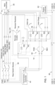
- is a schematic diagram of a remote tractor control assist system according to a first embodiment of the invention, and
- Fig. 2
- is an end view of a hand held remote control unit and a rear switch module on a tractor according to a first embodiment of the invention.
- In one embodiment shown in
Figs. 1 and2 , remotetractor control system 10 may include hand heldremote control unit 12 that an operator may use to provide wireless signals or commands while the operator is off the tractor, preferably at distances up to about 30 feet from the tractor, or while seated on the tractor facing rearwardly. The hand held remote control unit may transmit by short range radio or Bluetooth toremote receiver module 14 on the tractor. - In one embodiment, remote
tractor control system 10 may include hand heldremote control unit 12 having remote enablebutton 16 andcommand buttons 18 to 32 for functions such as attaching an implement that may be done while off the tractor or seated facing rearwardly. The remote enable button may function as a momentary safety switch to enable sending commands from the hand held remote control unit to the remote receiver module. The operator must hold the remote enable button at the same time as one of the command buttons. When the operator is not holding the remote enable button, the hand held remote control unit does not send commands to the remote receiver module. Instead, the hand held remote control unit may activatedisplay 34 which may show information about tractor condition from the engine controller such as engine speed, oil pressure, water temperature, or hydraulic fluid temperature, which may be transmitted byremote receiver module 14 on the tractor to the hand held remote control unit. - In one embodiment, remote
tractor control system 10 may include hand heldremote control unit 12 havingcommand buttons 18 and 20 to creep in forward or reverse,command buttons 22 to 24 to raise or lower the three point hitch,command buttons command buttons command buttons - The operator may use the rear switch module to provide three point hitch and creep commands to hitch
controller 38 andtransmission controller 40 unless the enable signal from hand heldremote control unit 12 is received throughremote receiver module 14. The rear switch module may includebuttons buttons button 50 which the operator must hold in order to operate the command buttons on the rear switch module. The tractor also may include controls in the operator station adjacent a forward facing seat for raising and lowering the three point hitch, and controls in the operator station adjacent the forward facing seat for operating the transmission in creep mode, forward or reverse. - In one embodiment, remote
tractor control system 10 may includeremote receiver module 14 mounted on the tractor. The remote receiver module may includeswitch 52 andrelay 54 to shut off 12V power to rearfender switch module 36 when the remote receiver module receives a remote enable signal from hand heldremoter control unit 12. The remote receiver module may use 12V power only to power the remote enable, and the other switches on the remote receiver module may be powered off ofrelay 54. The other switches may include three point hitch raise andlower switches 56, and creep forward andreverse switches 58. The three point hitch raise and lower switches, and the creep forward and reverse switches, may be actuated by commands that the remote receiver module receives from the hand held remote control unit when it is enabled. The three point hitch raise and lower switches may connect tohitch controller 38, and the creep forward and reverse switches may connect totransmission controller 40. Additionally, the remote receiver module may send commands received from the hand held remote control unit toengine controller 60, and send engine data from the engine controller to the had held remote control unit. For example, the remote receiver module may be connected to the engine controller via CANbus 62.
Claims (3)
- A remote tractor control system, comprising a hand held remote control unit (12) having a plurality of command buttons (16, 18,...,32) including buttons (18,...,32) for raising or lowering a three point hitch on a tractor and creeping the tractor in forward or reverse, and an enable button (16) that must be actuated to wirelessly transmit signals from each of the plurality of command buttons (18,...,32) to a remote receiver module (14) on the tractor, and a rear switch module (36) mounted on a rear fender of the tractor where the operator may use it while off the tractor also having buttons (42,... ,48) for raising or lowering the three point hitch and creeping in forward or reverse, the remote receiver module (14) disabling the rear switch module (36) when the enable button (16) on the hand held remote control unit (12) is actuated, wherein the hand held remote control unit (12) includes a display (34) that shows information about condition of the tractor when the enable button (16) is not actuated.
- The remote tractor control system according to claim 1, characterized in that the hand held remote control unit (12) includes buttons (26, 28) for operating a rear facing implement.
- The remote tractor control system according to one of claims 1 or 2, characterized by further comprising an enable switch (50) on the rear switch module (36).
Applications Claiming Priority (1)
| Application Number | Priority Date | Filing Date | Title |
|---|---|---|---|
| US16/114,653 US10802496B2 (en) | 2018-08-28 | 2018-08-28 | Remote tractor control system |
Publications (3)
| Publication Number | Publication Date |
|---|---|
| EP3616486A2 EP3616486A2 (en) | 2020-03-04 |
| EP3616486A3 EP3616486A3 (en) | 2020-04-08 |
| EP3616486B1 true EP3616486B1 (en) | 2023-07-26 |
Family
ID=67514336
Family Applications (1)
| Application Number | Title | Priority Date | Filing Date |
|---|---|---|---|
| EP19188837.9A Active EP3616486B1 (en) | 2018-08-28 | 2019-07-29 | Remote tractor control system |
Country Status (3)
| Country | Link |
|---|---|
| US (1) | US10802496B2 (en) |
| EP (1) | EP3616486B1 (en) |
| CN (1) | CN110865565B (en) |
Families Citing this family (6)
| Publication number | Priority date | Publication date | Assignee | Title |
|---|---|---|---|---|
| US20220183224A1 (en) * | 2020-12-14 | 2022-06-16 | Christopher M. Wilt | Remote Control for a Mower |
| WO2023127268A1 (en) * | 2021-12-28 | 2023-07-06 | 株式会社クボタ | Agricultural work assistance system, agricultural machine |
| WO2023205320A1 (en) * | 2022-04-20 | 2023-10-26 | Avbj, Llc | Multi-modal freight systems, devices, and methods |
| JP7840252B2 (en) * | 2022-11-29 | 2026-04-03 | 株式会社クボタ | Work vehicle |
| JP2025095181A (en) * | 2023-12-14 | 2025-06-26 | ヤンマーホールディングス株式会社 | Work vehicles |
| EP4631761A1 (en) * | 2024-04-08 | 2025-10-15 | Deere & Company | Remote control device for an agricultural tractor |
Family Cites Families (31)
| Publication number | Priority date | Publication date | Assignee | Title |
|---|---|---|---|---|
| US4715012A (en) | 1980-10-15 | 1987-12-22 | Massey-Ferguson Services N.V. | Electronic tractor control |
| EP0251529B1 (en) * | 1986-06-14 | 1991-01-30 | Massey-Ferguson Services N.V. | Tractor hitch control system |
| US4869337A (en) * | 1987-10-15 | 1989-09-26 | Clark Equipment Company | Backhoe creep lever mechanism for an excavating vehicle |
| US5190118A (en) * | 1991-11-01 | 1993-03-02 | Yelton James E | Auxiliary power train and steering system for a vehicle |
| US5205181A (en) * | 1992-02-03 | 1993-04-27 | Vermeer Manufacturing Company | Manual motion control override apparatus |
| US5421416A (en) * | 1993-09-08 | 1995-06-06 | Case Corporation | Hitch assembly control system |
| JPH07184406A (en) | 1993-12-28 | 1995-07-25 | Seibutsukei Tokutei Sangyo Gijutsu Kenkyu Suishin Kiko | Agricultural handling equipment |
| DE4428368C2 (en) | 1994-08-11 | 1997-11-27 | Deere & Co | PTO control |
| US6112139A (en) | 1998-10-29 | 2000-08-29 | Case Corporation | Apparatus and method for wireless remote control of an operation of a work vehicle |
| GB2344157A (en) * | 1998-11-28 | 2000-05-31 | New Holland | Remote control of an agricultural vehicle. |
| US6134494A (en) | 1999-04-20 | 2000-10-17 | Case Corporation | Automatic power takeoff control system |
| US6173225B1 (en) * | 1999-04-20 | 2001-01-09 | Case Corporation | Power takeoff control system |
| WO2001036234A1 (en) * | 1999-11-17 | 2001-05-25 | Vehicle Enhancement Systems, Inc. | Method for data communication between a vehicle and a remote terminal |
| US6851495B2 (en) | 2001-10-19 | 2005-02-08 | Deere & Co. | Speed control for utility vehicle operable from rearward-facing seat |
| US7721840B2 (en) * | 2007-05-11 | 2010-05-25 | Deere & Company | Creep steering control system operable from rearward-facing position |
| US8185276B2 (en) * | 2008-06-17 | 2012-05-22 | Sno-Way International, Inc. | Programmable wireless remote control system and method for snow plows |
| JP2011120540A (en) * | 2009-12-11 | 2011-06-23 | Matsuyama Plow Mfg Co Ltd | Remote control system of agricultural implement |
| US20110202201A1 (en) * | 2010-02-12 | 2011-08-18 | Fujitsu Ten Limited | Remote starting device and remote starting method |
| US8656081B2 (en) * | 2010-03-12 | 2014-02-18 | The United States Of America As Represented By The Secretary Of The Navy | System and method for coordinating control of an output device by multiple control consoles |
| US8322482B2 (en) * | 2010-09-27 | 2012-12-04 | Deere & Company | Tractor ground positioning system |
| US8272467B1 (en) * | 2011-03-04 | 2012-09-25 | Staab Michael A | Remotely controlled backhoe |
| US9213331B2 (en) * | 2012-12-19 | 2015-12-15 | Caterpillar Inc. | Remote control system for a machine |
| US9050890B2 (en) * | 2013-08-15 | 2015-06-09 | Deere & Company | Vehicle positioning system |
| CN104597787B (en) * | 2014-12-15 | 2019-03-12 | 北京新能源汽车股份有限公司 | Method and system for remotely controlling air conditioner of electric automobile |
| US9346394B1 (en) * | 2015-01-16 | 2016-05-24 | Meyer Products, Llc | Method and apparatus for installing and operating an auxiliary lighting system using a vehicle light plug |
| US9981597B2 (en) * | 2015-01-16 | 2018-05-29 | Meyer Products Llc | Method and apparatus for installing and operating an auxiliary lighting system using a vehicle electric plug |
| AU2015101471A4 (en) * | 2015-10-12 | 2016-02-04 | Cms Sales Pty Ltd | Tractor remote control |
| US20170151969A1 (en) * | 2015-12-01 | 2017-06-01 | Laird Technologies, Inc. | Systems and methods for safety locking of operator control units for remote control machines |
| CN106205086A (en) * | 2016-07-12 | 2016-12-07 | 江苏大学 | A kind of remote control unit for pure electric caterpillar band tractor and control method |
| US10276037B2 (en) * | 2016-12-12 | 2019-04-30 | Cnh Industrial America Llc | Method of adjusting tillage equipment remotely from outside a tractor cab |
| CN106871964A (en) * | 2017-02-23 | 2017-06-20 | 北京农业智能装备技术研究中心 | A kind of straw-returning operation remote monitoring device and method |
-
2018
- 2018-08-28 US US16/114,653 patent/US10802496B2/en active Active
-
2019
- 2019-07-29 EP EP19188837.9A patent/EP3616486B1/en active Active
- 2019-08-21 CN CN201910773982.0A patent/CN110865565B/en active Active
Also Published As
| Publication number | Publication date |
|---|---|
| EP3616486A2 (en) | 2020-03-04 |
| US10802496B2 (en) | 2020-10-13 |
| CN110865565B (en) | 2024-06-25 |
| EP3616486A3 (en) | 2020-04-08 |
| CN110865565A (en) | 2020-03-06 |
| US20200073397A1 (en) | 2020-03-05 |
Similar Documents
| Publication | Publication Date | Title |
|---|---|---|
| EP3616486A2 (en) | Remote tractor control system | |
| US9622399B2 (en) | Arrangement for the control of a device interface of an agricultural work vehicle | |
| EP3440523B1 (en) | Status indicator for an autonomous agricultural vehicle | |
| US11157162B2 (en) | Autonomous agricultural system user interface interlock | |
| US6205385B1 (en) | Power takeoff control switches | |
| EP2433482B1 (en) | Tractor ground positioning system | |
| EP2195491B1 (en) | An automated control module for a power machine | |
| JP2021166520A (en) | Autonomous driving work vehicle | |
| WO2013026661A1 (en) | Agricultural tractor linkage control system | |
| US6105679A (en) | Control system for a hitched or trailed implement | |
| EP2878186B1 (en) | Agricultural implement, such as an extendable brush cutter, with improved safety for removable attachment to a tractor | |
| JP2017177934A (en) | Work vehicle | |
| EP3523482B1 (en) | An implement for a working vehicle and a method for controlling the implement | |
| JP2017175980A (en) | Remote controller | |
| EP3420789B1 (en) | Method for operating an agricultural system and agricultural system | |
| JP7844008B2 (en) | Safety control system for agricultural machinery | |
| JP6238752B2 (en) | Work vehicle | |
| JP2021058156A (en) | Communication system for working machine | |
| EP4242033A1 (en) | Method for controlling an inching functionality of a work vehicle | |
| JP6479089B2 (en) | Work vehicle | |
| JP2008074131A (en) | PTO clutch operation structure of work vehicle |
Legal Events
| Date | Code | Title | Description |
|---|---|---|---|
| PUAI | Public reference made under article 153(3) epc to a published international application that has entered the european phase |
Free format text: ORIGINAL CODE: 0009012 |
|
| STAA | Information on the status of an ep patent application or granted ep patent |
Free format text: STATUS: THE APPLICATION HAS BEEN PUBLISHED |
|
| AK | Designated contracting states |
Kind code of ref document: A2 Designated state(s): AL AT BE BG CH CY CZ DE DK EE ES FI FR GB GR HR HU IE IS IT LI LT LU LV MC MK MT NL NO PL PT RO RS SE SI SK SM TR |
|
| AX | Request for extension of the european patent |
Extension state: BA ME |
|
| PUAL | Search report despatched |
Free format text: ORIGINAL CODE: 0009013 |
|
| AK | Designated contracting states |
Kind code of ref document: A3 Designated state(s): AL AT BE BG CH CY CZ DE DK EE ES FI FR GB GR HR HU IE IS IT LI LT LU LV MC MK MT NL NO PL PT RO RS SE SI SK SM TR |
|
| AX | Request for extension of the european patent |
Extension state: BA ME |
|
| RIC1 | Information provided on ipc code assigned before grant |
Ipc: A01B 76/00 20060101ALI20200304BHEP Ipc: A01B 59/06 20060101AFI20200304BHEP Ipc: A01B 69/00 20060101ALI20200304BHEP |
|
| STAA | Information on the status of an ep patent application or granted ep patent |
Free format text: STATUS: REQUEST FOR EXAMINATION WAS MADE |
|
| 17P | Request for examination filed |
Effective date: 20201008 |
|
| RBV | Designated contracting states (corrected) |
Designated state(s): AL AT BE BG CH CY CZ DE DK EE ES FI FR GB GR HR HU IE IS IT LI LT LU LV MC MK MT NL NO PL PT RO RS SE SI SK SM TR |
|
| STAA | Information on the status of an ep patent application or granted ep patent |
Free format text: STATUS: EXAMINATION IS IN PROGRESS |
|
| 17Q | First examination report despatched |
Effective date: 20220218 |
|
| GRAP | Despatch of communication of intention to grant a patent |
Free format text: ORIGINAL CODE: EPIDOSNIGR1 |
|
| STAA | Information on the status of an ep patent application or granted ep patent |
Free format text: STATUS: GRANT OF PATENT IS INTENDED |
|
| INTG | Intention to grant announced |
Effective date: 20230222 |
|
| GRAS | Grant fee paid |
Free format text: ORIGINAL CODE: EPIDOSNIGR3 |
|
| GRAA | (expected) grant |
Free format text: ORIGINAL CODE: 0009210 |
|
| STAA | Information on the status of an ep patent application or granted ep patent |
Free format text: STATUS: THE PATENT HAS BEEN GRANTED |
|
| AK | Designated contracting states |
Kind code of ref document: B1 Designated state(s): AL AT BE BG CH CY CZ DE DK EE ES FI FR GB GR HR HU IE IS IT LI LT LU LV MC MK MT NL NO PL PT RO RS SE SI SK SM TR |
|
| REG | Reference to a national code |
Ref country code: CH Ref legal event code: EP |
|
| REG | Reference to a national code |
Ref country code: DE Ref legal event code: R096 Ref document number: 602019033399 Country of ref document: DE |
|
| REG | Reference to a national code |
Ref country code: IE Ref legal event code: FG4D |
|
| REG | Reference to a national code |
Ref country code: LT Ref legal event code: MG9D |
|
| REG | Reference to a national code |
Ref country code: NL Ref legal event code: MP Effective date: 20230726 |
|
| REG | Reference to a national code |
Ref country code: AT Ref legal event code: MK05 Ref document number: 1590815 Country of ref document: AT Kind code of ref document: T Effective date: 20230726 |
|
| PG25 | Lapsed in a contracting state [announced via postgrant information from national office to epo] |
Ref country code: NL Free format text: LAPSE BECAUSE OF FAILURE TO SUBMIT A TRANSLATION OF THE DESCRIPTION OR TO PAY THE FEE WITHIN THE PRESCRIBED TIME-LIMIT Effective date: 20230726 |
|
| PG25 | Lapsed in a contracting state [announced via postgrant information from national office to epo] |
Ref country code: GR Free format text: LAPSE BECAUSE OF FAILURE TO SUBMIT A TRANSLATION OF THE DESCRIPTION OR TO PAY THE FEE WITHIN THE PRESCRIBED TIME-LIMIT Effective date: 20231027 |
|
| PG25 | Lapsed in a contracting state [announced via postgrant information from national office to epo] |
Ref country code: IS Free format text: LAPSE BECAUSE OF FAILURE TO SUBMIT A TRANSLATION OF THE DESCRIPTION OR TO PAY THE FEE WITHIN THE PRESCRIBED TIME-LIMIT Effective date: 20231126 |
|
| PG25 | Lapsed in a contracting state [announced via postgrant information from national office to epo] |
Ref country code: SE Free format text: LAPSE BECAUSE OF FAILURE TO SUBMIT A TRANSLATION OF THE DESCRIPTION OR TO PAY THE FEE WITHIN THE PRESCRIBED TIME-LIMIT Effective date: 20230726 Ref country code: RS Free format text: LAPSE BECAUSE OF FAILURE TO SUBMIT A TRANSLATION OF THE DESCRIPTION OR TO PAY THE FEE WITHIN THE PRESCRIBED TIME-LIMIT Effective date: 20230726 Ref country code: PT Free format text: LAPSE BECAUSE OF FAILURE TO SUBMIT A TRANSLATION OF THE DESCRIPTION OR TO PAY THE FEE WITHIN THE PRESCRIBED TIME-LIMIT Effective date: 20231127 Ref country code: NO Free format text: LAPSE BECAUSE OF FAILURE TO SUBMIT A TRANSLATION OF THE DESCRIPTION OR TO PAY THE FEE WITHIN THE PRESCRIBED TIME-LIMIT Effective date: 20231026 Ref country code: LV Free format text: LAPSE BECAUSE OF FAILURE TO SUBMIT A TRANSLATION OF THE DESCRIPTION OR TO PAY THE FEE WITHIN THE PRESCRIBED TIME-LIMIT Effective date: 20230726 Ref country code: LT Free format text: LAPSE BECAUSE OF FAILURE TO SUBMIT A TRANSLATION OF THE DESCRIPTION OR TO PAY THE FEE WITHIN THE PRESCRIBED TIME-LIMIT Effective date: 20230726 Ref country code: IS Free format text: LAPSE BECAUSE OF FAILURE TO SUBMIT A TRANSLATION OF THE DESCRIPTION OR TO PAY THE FEE WITHIN THE PRESCRIBED TIME-LIMIT Effective date: 20231126 Ref country code: HR Free format text: LAPSE BECAUSE OF FAILURE TO SUBMIT A TRANSLATION OF THE DESCRIPTION OR TO PAY THE FEE WITHIN THE PRESCRIBED TIME-LIMIT Effective date: 20230726 Ref country code: GR Free format text: LAPSE BECAUSE OF FAILURE TO SUBMIT A TRANSLATION OF THE DESCRIPTION OR TO PAY THE FEE WITHIN THE PRESCRIBED TIME-LIMIT Effective date: 20231027 Ref country code: FI Free format text: LAPSE BECAUSE OF FAILURE TO SUBMIT A TRANSLATION OF THE DESCRIPTION OR TO PAY THE FEE WITHIN THE PRESCRIBED TIME-LIMIT Effective date: 20230726 Ref country code: AT Free format text: LAPSE BECAUSE OF FAILURE TO SUBMIT A TRANSLATION OF THE DESCRIPTION OR TO PAY THE FEE WITHIN THE PRESCRIBED TIME-LIMIT Effective date: 20230726 |
|
| PG25 | Lapsed in a contracting state [announced via postgrant information from national office to epo] |
Ref country code: PL Free format text: LAPSE BECAUSE OF FAILURE TO SUBMIT A TRANSLATION OF THE DESCRIPTION OR TO PAY THE FEE WITHIN THE PRESCRIBED TIME-LIMIT Effective date: 20230726 |
|
| REG | Reference to a national code |
Ref country code: CH Ref legal event code: PL |
|
| REG | Reference to a national code |
Ref country code: BE Ref legal event code: MM Effective date: 20230731 |
|
| PG25 | Lapsed in a contracting state [announced via postgrant information from national office to epo] |
Ref country code: LU Free format text: LAPSE BECAUSE OF NON-PAYMENT OF DUE FEES Effective date: 20230729 |
|
| PG25 | Lapsed in a contracting state [announced via postgrant information from national office to epo] |
Ref country code: LU Free format text: LAPSE BECAUSE OF NON-PAYMENT OF DUE FEES Effective date: 20230729 |
|
| REG | Reference to a national code |
Ref country code: IE Ref legal event code: MM4A |
|
| PG25 | Lapsed in a contracting state [announced via postgrant information from national office to epo] |
Ref country code: ES Free format text: LAPSE BECAUSE OF FAILURE TO SUBMIT A TRANSLATION OF THE DESCRIPTION OR TO PAY THE FEE WITHIN THE PRESCRIBED TIME-LIMIT Effective date: 20230726 |
|
| REG | Reference to a national code |
Ref country code: DE Ref legal event code: R097 Ref document number: 602019033399 Country of ref document: DE |
|
| PG25 | Lapsed in a contracting state [announced via postgrant information from national office to epo] |
Ref country code: SM Free format text: LAPSE BECAUSE OF FAILURE TO SUBMIT A TRANSLATION OF THE DESCRIPTION OR TO PAY THE FEE WITHIN THE PRESCRIBED TIME-LIMIT Effective date: 20230726 Ref country code: RO Free format text: LAPSE BECAUSE OF FAILURE TO SUBMIT A TRANSLATION OF THE DESCRIPTION OR TO PAY THE FEE WITHIN THE PRESCRIBED TIME-LIMIT Effective date: 20230726 Ref country code: ES Free format text: LAPSE BECAUSE OF FAILURE TO SUBMIT A TRANSLATION OF THE DESCRIPTION OR TO PAY THE FEE WITHIN THE PRESCRIBED TIME-LIMIT Effective date: 20230726 Ref country code: EE Free format text: LAPSE BECAUSE OF FAILURE TO SUBMIT A TRANSLATION OF THE DESCRIPTION OR TO PAY THE FEE WITHIN THE PRESCRIBED TIME-LIMIT Effective date: 20230726 Ref country code: DK Free format text: LAPSE BECAUSE OF FAILURE TO SUBMIT A TRANSLATION OF THE DESCRIPTION OR TO PAY THE FEE WITHIN THE PRESCRIBED TIME-LIMIT Effective date: 20230726 Ref country code: CZ Free format text: LAPSE BECAUSE OF FAILURE TO SUBMIT A TRANSLATION OF THE DESCRIPTION OR TO PAY THE FEE WITHIN THE PRESCRIBED TIME-LIMIT Effective date: 20230726 Ref country code: MC Free format text: LAPSE BECAUSE OF FAILURE TO SUBMIT A TRANSLATION OF THE DESCRIPTION OR TO PAY THE FEE WITHIN THE PRESCRIBED TIME-LIMIT Effective date: 20230726 Ref country code: CH Free format text: LAPSE BECAUSE OF NON-PAYMENT OF DUE FEES Effective date: 20230731 Ref country code: SK Free format text: LAPSE BECAUSE OF FAILURE TO SUBMIT A TRANSLATION OF THE DESCRIPTION OR TO PAY THE FEE WITHIN THE PRESCRIBED TIME-LIMIT Effective date: 20230726 |
|
| PG25 | Lapsed in a contracting state [announced via postgrant information from national office to epo] |
Ref country code: IT Free format text: LAPSE BECAUSE OF FAILURE TO SUBMIT A TRANSLATION OF THE DESCRIPTION OR TO PAY THE FEE WITHIN THE PRESCRIBED TIME-LIMIT Effective date: 20230726 Ref country code: BE Free format text: LAPSE BECAUSE OF NON-PAYMENT OF DUE FEES Effective date: 20230731 |
|
| PLBE | No opposition filed within time limit |
Free format text: ORIGINAL CODE: 0009261 |
|
| STAA | Information on the status of an ep patent application or granted ep patent |
Free format text: STATUS: NO OPPOSITION FILED WITHIN TIME LIMIT |
|
| 26N | No opposition filed |
Effective date: 20240429 |
|
| PG25 | Lapsed in a contracting state [announced via postgrant information from national office to epo] |
Ref country code: IE Free format text: LAPSE BECAUSE OF NON-PAYMENT OF DUE FEES Effective date: 20230729 |
|
| PG25 | Lapsed in a contracting state [announced via postgrant information from national office to epo] |
Ref country code: IE Free format text: LAPSE BECAUSE OF NON-PAYMENT OF DUE FEES Effective date: 20230729 Ref country code: FR Free format text: LAPSE BECAUSE OF NON-PAYMENT OF DUE FEES Effective date: 20230926 Ref country code: SI Free format text: LAPSE BECAUSE OF FAILURE TO SUBMIT A TRANSLATION OF THE DESCRIPTION OR TO PAY THE FEE WITHIN THE PRESCRIBED TIME-LIMIT Effective date: 20230726 |
|
| PG25 | Lapsed in a contracting state [announced via postgrant information from national office to epo] |
Ref country code: BG Free format text: LAPSE BECAUSE OF FAILURE TO SUBMIT A TRANSLATION OF THE DESCRIPTION OR TO PAY THE FEE WITHIN THE PRESCRIBED TIME-LIMIT Effective date: 20230726 |
|
| PG25 | Lapsed in a contracting state [announced via postgrant information from national office to epo] |
Ref country code: BG Free format text: LAPSE BECAUSE OF FAILURE TO SUBMIT A TRANSLATION OF THE DESCRIPTION OR TO PAY THE FEE WITHIN THE PRESCRIBED TIME-LIMIT Effective date: 20230726 |
|
| PG25 | Lapsed in a contracting state [announced via postgrant information from national office to epo] |
Ref country code: CY Free format text: LAPSE BECAUSE OF FAILURE TO SUBMIT A TRANSLATION OF THE DESCRIPTION OR TO PAY THE FEE WITHIN THE PRESCRIBED TIME-LIMIT; INVALID AB INITIO Effective date: 20190729 |
|
| PG25 | Lapsed in a contracting state [announced via postgrant information from national office to epo] |
Ref country code: HU Free format text: LAPSE BECAUSE OF FAILURE TO SUBMIT A TRANSLATION OF THE DESCRIPTION OR TO PAY THE FEE WITHIN THE PRESCRIBED TIME-LIMIT; INVALID AB INITIO Effective date: 20190729 |
|
| PGFP | Annual fee paid to national office [announced via postgrant information from national office to epo] |
Ref country code: DE Payment date: 20250620 Year of fee payment: 7 |
|
| PGFP | Annual fee paid to national office [announced via postgrant information from national office to epo] |
Ref country code: GB Payment date: 20250728 Year of fee payment: 7 |
|
| PG25 | Lapsed in a contracting state [announced via postgrant information from national office to epo] |
Ref country code: TR Free format text: LAPSE BECAUSE OF FAILURE TO SUBMIT A TRANSLATION OF THE DESCRIPTION OR TO PAY THE FEE WITHIN THE PRESCRIBED TIME-LIMIT Effective date: 20230726 |