EP3616450B1 - Multiple starting positions for uplink transmission on unlicensed spectrum - Google Patents
Multiple starting positions for uplink transmission on unlicensed spectrum Download PDFInfo
- Publication number
- EP3616450B1 EP3616450B1 EP18723071.9A EP18723071A EP3616450B1 EP 3616450 B1 EP3616450 B1 EP 3616450B1 EP 18723071 A EP18723071 A EP 18723071A EP 3616450 B1 EP3616450 B1 EP 3616450B1
- Authority
- EP
- European Patent Office
- Prior art keywords
- subframe
- slot
- wireless communication
- communication device
- full
- Prior art date
- Legal status (The legal status is an assumption and is not a legal conclusion. Google has not performed a legal analysis and makes no representation as to the accuracy of the status listed.)
- Active
Links
Images


Classifications
-
- H—ELECTRICITY
- H04—ELECTRIC COMMUNICATION TECHNIQUE
- H04W—WIRELESS COMMUNICATION NETWORKS
- H04W72/00—Local resource management
- H04W72/04—Wireless resource allocation
- H04W72/044—Wireless resource allocation based on the type of the allocated resource
- H04W72/0446—Resources in time domain, e.g. slots or frames
-
- H—ELECTRICITY
- H04—ELECTRIC COMMUNICATION TECHNIQUE
- H04L—TRANSMISSION OF DIGITAL INFORMATION, e.g. TELEGRAPHIC COMMUNICATION
- H04L1/00—Arrangements for detecting or preventing errors in the information received
- H04L1/12—Arrangements for detecting or preventing errors in the information received by using return channel
- H04L1/16—Arrangements for detecting or preventing errors in the information received by using return channel in which the return channel carries supervisory signals, e.g. repetition request signals
- H04L1/18—Automatic repetition systems, e.g. Van Duuren systems
- H04L1/1812—Hybrid protocols; Hybrid automatic repeat request [HARQ]
- H04L1/1819—Hybrid protocols; Hybrid automatic repeat request [HARQ] with retransmission of additional or different redundancy
-
- H—ELECTRICITY
- H04—ELECTRIC COMMUNICATION TECHNIQUE
- H04L—TRANSMISSION OF DIGITAL INFORMATION, e.g. TELEGRAPHIC COMMUNICATION
- H04L1/00—Arrangements for detecting or preventing errors in the information received
- H04L1/12—Arrangements for detecting or preventing errors in the information received by using return channel
- H04L1/16—Arrangements for detecting or preventing errors in the information received by using return channel in which the return channel carries supervisory signals, e.g. repetition request signals
- H04L1/18—Automatic repetition systems, e.g. Van Duuren systems
- H04L1/1867—Arrangements specially adapted for the transmitter end
- H04L1/1874—Buffer management
-
- H—ELECTRICITY
- H04—ELECTRIC COMMUNICATION TECHNIQUE
- H04L—TRANSMISSION OF DIGITAL INFORMATION, e.g. TELEGRAPHIC COMMUNICATION
- H04L1/00—Arrangements for detecting or preventing errors in the information received
- H04L1/12—Arrangements for detecting or preventing errors in the information received by using return channel
- H04L1/16—Arrangements for detecting or preventing errors in the information received by using return channel in which the return channel carries supervisory signals, e.g. repetition request signals
- H04L1/18—Automatic repetition systems, e.g. Van Duuren systems
- H04L1/1867—Arrangements specially adapted for the transmitter end
- H04L1/1887—Scheduling and prioritising arrangements
-
- H—ELECTRICITY
- H04—ELECTRIC COMMUNICATION TECHNIQUE
- H04L—TRANSMISSION OF DIGITAL INFORMATION, e.g. TELEGRAPHIC COMMUNICATION
- H04L27/00—Modulated-carrier systems
- H04L27/0006—Assessment of spectral gaps suitable for allocating digitally modulated signals, e.g. for carrier allocation in cognitive radio
-
- H—ELECTRICITY
- H04—ELECTRIC COMMUNICATION TECHNIQUE
- H04L—TRANSMISSION OF DIGITAL INFORMATION, e.g. TELEGRAPHIC COMMUNICATION
- H04L5/00—Arrangements affording multiple use of the transmission path
- H04L5/0091—Signaling for the administration of the divided path
- H04L5/0094—Indication of how sub-channels of the path are allocated
-
- H—ELECTRICITY
- H04—ELECTRIC COMMUNICATION TECHNIQUE
- H04W—WIRELESS COMMUNICATION NETWORKS
- H04W16/00—Network planning, e.g. coverage or traffic planning tools; Network deployment, e.g. resource partitioning or cells structures
- H04W16/14—Spectrum sharing arrangements between different networks
-
- H—ELECTRICITY
- H04—ELECTRIC COMMUNICATION TECHNIQUE
- H04W—WIRELESS COMMUNICATION NETWORKS
- H04W72/00—Local resource management
- H04W72/12—Wireless traffic scheduling
- H04W72/1263—Mapping of traffic onto schedule, e.g. scheduled allocation or multiplexing of flows
- H04W72/1268—Mapping of traffic onto schedule, e.g. scheduled allocation or multiplexing of flows of uplink data flows
-
- H—ELECTRICITY
- H04—ELECTRIC COMMUNICATION TECHNIQUE
- H04W—WIRELESS COMMUNICATION NETWORKS
- H04W74/00—Wireless channel access, e.g. scheduled or random access
- H04W74/08—Non-scheduled or contention based access, e.g. random access, ALOHA, CSMA [Carrier Sense Multiple Access]
- H04W74/0808—Non-scheduled or contention based access, e.g. random access, ALOHA, CSMA [Carrier Sense Multiple Access] using carrier sensing, e.g. as in CSMA
Definitions
- the disclosed subject matter relates generally to telecommunications. Certain embodiments relate more particularly to concepts such as Licensed-assisted access, Long Term Evolution (LTE) uplink transmissions and Contention Window (CW) adjustment.
- LTE Long Term Evolution
- CW Contention Window
- LAA Licensed-Assisted Access
- LTE Long Term Evolution
- GHz gigahertz
- 3.5 GHz 3.5 GHz
- the unlicensed spectrum is used as a complement to the licensed spectrum or allows completely standalone operation.
- CA carrier aggregation
- LBT listen-before-talk
- Wi-Fi Wireless Local Area Network
- LTE uses Orthogonal Frequency Division Multiplexing (OFDM) in the downlink and Discrete Fourier Transform (DFT)-spread OFDM (also referred to as single-carrier Frequency Division Multiple Access (FDMA)) in the uplink.
- OFDM Orthogonal Frequency Division Multiplexing
- DFT Discrete Fourier Transform
- FDMA single-carrier Frequency Division Multiple Access
- the basic LTE downlink physical resource can thus be seen as a time-frequency grid as illustrated in Figure 1 where each resource element corresponds to one OFDM subcarrier during one OFDM symbol interval.
- the uplink subframe has the same subcarrier spacing as the downlink and the same number of Single Carrier FDMA (SC-FDMA) symbols in the time domain as OFDM symbols in the downlink.
- SC-FDMA Single Carrier FDMA
- Each subframe comprises two slots of duration 0.5 ms each, and the slot numbering within a frame ranges from 0 to 19.
- one subframe consists of 14 OFDM symbols. The duration of each symbol is approximately 71.4 ⁇ s.
- resource allocation in LTE is typically described in terms of resource blocks, where a resource block corresponds to one slot (0.5 ms) in the time domain and 12 contiguous subcarriers in the frequency domain.
- a pair of two adjacent resource blocks in time direction (1.0 ms) is known as a resource block pair.
- Resource blocks are numbered in the frequency domain, starting with 0 from one end of the system bandwidth.
- Downlink transmissions are dynamically scheduled, i.e., in each subframe the base station transmits control information about which terminals data is transmitted to and upon which resource blocks the data is transmitted, in the current downlink subframe.
- CFI Control Format Indicator
- the downlink subframe also contains common reference symbols, which are known to the receiver and used for coherent demodulation of e.g. the control information.
- the reference symbols shown in Figure 3 are the cell specific reference symbols (CRS) and are used to support multiple functions including fine time and frequency synchronization and channel estimation for certain transmission modes.
- CRS cell specific reference symbols
- Uplink transmissions are dynamically scheduled, i.e., in each downlink subframe the base station transmits control information about which terminals should transmit data to the eNB in subsequent subframes, and upon which resource blocks the data is transmitted.
- the uplink resource grid is comprised of data and uplink control information in the Physical Uplink Shared Channel (PUSCH), uplink control information in the Physical Uplink Control Channel (PUCCH), and various reference signals such as Demodulation Reference Signals (DMRS) and Sounding Reference Signals (SRS).
- PUSCH Physical Uplink Shared Channel
- PUCCH Physical Uplink Control Channel
- various reference signals such as Demodulation Reference Signals (DMRS) and Sounding Reference Signals (SRS).
- DMRSs are used for coherent demodulation of PUSCH and PUCCH data
- SRSs are not associated with any data or control information but are generally used to estimate the uplink channel quality for purposes of frequency-selective scheduling.
- FIG. 4 An example uplink subframe is shown in Figure 4 .
- UL DMRS and SRS are time-multiplexed into the UL subframe, and SRS are always transmitted in the last symbol of a normal UL subframe.
- the PUSCH DMRS is transmitted once every slot for subframes with normal cyclic prefix, and is located in the fourth and eleventh SC-FDMA symbols.
- DL or UL resource assignments can also be scheduled on the enhanced Physical Downlink Control Channel (EPDCCH).
- EPCCH Physical Downlink Control Channel
- PDCCH Physical Downlink Control Channel
- Resource grants are UE specific and are indicated by scrambling the Downlink Control Information (DCI) Cyclic Redundancy Check (CRC) with the User Equipment (UE)-specific Cell Radio Network Temporary Identifier (C-RNTI).
- DCI Downlink Control Information
- CRC Cyclic Redundancy Check
- UE User Equipment
- C-RNTI Cell Radio Network Temporary Identifier
- a unique C-RNTI is assigned by a cell to every UE associated with it, and can take values in the range 0001-FFF3 in hexadecimal format.
- a UE uses the same C-RNTI on all serving cells.
- the uplink access is typically controlled by eNB, i.e., scheduled.
- the UE would report to the eNB when data is available to be transmitted, e.g., by sending a scheduling request message (SR).
- SR scheduling request message
- the eNB would grant the resources and relevant information to the UE in order to carry out the transmission of a certain size of data.
- the assigned resources are not necessarily sufficient for the UE to transmit all the available data. Therefore, it is possible that the UE sends a buffer status report (BSR) control message in the granted resources, in order to inform the eNB about the correct size and updated size of the data waiting for transmission. Based on that, the eNB would further grant the resources to carry on with the UE uplink transmission of the corrected size of data.
- BSR buffer status report
- the UE In case the UE is not Radio Resource Control (RRC) connected in LTE or lost its uplink synchronization since it did not transmit or receive anything for a certain time, the UE would use the random access procedure to connect to the network, obtain synchronization and also send the SR. If this is the case, the procedure until the data can be sent would take even longer than the SR transmission on PUCCH.
- RRC Radio Resource Control
- DCI downlink control information
- the DCI is first protected by 16-bit CRC.
- the CRC bits are further scrambled by the UE assigned identity (C-RNTI).
- C-RNTI UE assigned identity
- the DCI and scrambled CRC bits are further protected by convolutional coding.
- the encoded bits are transmitted from the eNB to UE using either PDCCH or EPDCCH.
- the UE transmits transmissions using a Type 1 channel access procedure that are associated with channel access priority class p on a carrier, the UE maintains the contention window value CW p and adjusts CW p for those transmissions, using the following procedure:
- LTE the spectrum used by LTE is dedicated to LTE. This has the advantage that LTE system does not need to care about the coexistence issue and the spectrum efficiency can be maximized.
- the spectrum allocated to LTE is limited which cannot meet the ever increasing demand for larger throughput from applications/services. Therefore, Rel-13 Licensed-assisted access (LAA) extended LTE to exploit unlicensed spectrum is required in addition to licensed spectrum. Unlicensed spectrum can, by definition, be simultaneously used by multiple different technologies. Therefore, LTE needs to consider the coexistence issue with other systems such as IEEE 802.11 (Wi-Fi). Operating LTE in the same manner in unlicensed spectrum as in licensed spectrum can seriously degrade the performance of Wi-Fi, as Wi-Fi will not transmit once it detects the channel is occupied.
- Wi-Fi IEEE 802.11
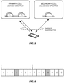
- one way to utilize the unlicensed spectrum reliably is to transmit essential control signals and channels on a licensed carrier. That is, as shown in Figure 5 , a UE is connected to a PCell in the licensed band and one or more SCells in the unlicensed band.
- LAA SCell licensed-assisted access secondary cell
- no licensed cell is available for uplink control signal transmissions.
- WO 2017/049560 A1 discloses a user equipment and a wireless communication method for LAA.
- the user equipment comprises a receiver operative to receive a UL grant which schedules a subframe for UL transmission, a first circuit operative to perform LBT, a transmitter operative to transmit a PUSCH in the scheduled subframe starting from one available starting position of multiple candidate starting positions in the scheduled subframe if the LBT is successful.
- a receiver operative to receive a UL grant which schedules a subframe for UL transmission
- a first circuit operative to perform LBT
- a transmitter operative to transmit a PUSCH in the scheduled subframe starting from one available starting position of multiple candidate starting positions in the scheduled subframe if the LBT is successful.
- US 2017/041805 A1 discloses a mobile device obtaining data to be wirelessly transmitted over a shared spectrum in an uplink channel to a base station.
- the uplink channel is formatted with a frame/subframe structure with a predetermined timing.
- the mobile device determines whether the shared spectrum is free for transmission according to a Listen Before Transmit procedure.
- the mobile device selects a start time in the uplink channel that mitigates interference from other mobile devices in proximity to the mobile device. Beginning at the start time, the mobile device transmits the data over the shared spectrum in the uplink channel to the base station.
- a method of operating a wireless communication device includes identifying candidate starting positions for an uplink (UL) transmission in an unlicensed spectrum and selecting at least one starting position from among the candidate start positions based on autonomous UL starting points according to an outcome of a listen-before-talk (LBT) procedure performed with respect to the unlicensed spectrum and/or one or more fixed UL starting points signaled in an UL grant.
- LBT listen-before-talk
- selecting the at least one starting position is based on autonomous UL starting points, and the method also includes, if a channel is obtained at a subframe boundary, transmitting a whole transport block (TB) on a full subframe.
- TB transport block
- selecting the at least one starting position is based on autonomous UL starting points, and the method also includes, if a channel is not obtained at a subframe boundary, puncturing a TB and transmitting a partial subframe depending on LBT outcome.
- the method also includes retransmitting the discarded part of the TB in the last scheduled uplink subframe using the same HARQ process ID as the punctured subframe. In some embodiments, the method also includes retransmitting a whole TB in the last scheduled uplink subframe using the same HARQ process ID as the punctured subframe.
- the method also includes retransmitting autonomously the discarded part of the TB in the next subframe after the scheduled uplink subframes. In some embodiments, the method also includes retransmitting autonomously the whole TB in the next subframe after scheduled uplink subframes.
- the method also includes obtaining an UL grant from an eNB; and determining if the wireless communication device is allowed to autonomously transmit after scheduled uplink subframe based on the UL grant from the eNB.
- the method also includes transmitting the discarded part of the TB, if the wireless communication device does not transmit a full first subframe. In some embodiments, where the wireless communication device is not allowed to autonomously transmit after scheduled uplink subframe, the method also includes waiting for a full or partial subframe retransmission schedule.
- the method also includes obtaining a scheduling decision of X subframes followed by a predetermined partial or full subframe.
- the scheduling of a partial UL subframe is received by the wireless communication device in a grant indicating that the wireless communication device shall stop UL transmission in the partial UL subframe at a UL ending point earlier than the last symbol.
- the method also includes puncturing the TB for first subframe; and retransmitting the discarded part of TB or the full TB on the predetermined subframe scheduled at the end of transmission burst using same HARQ process ID as the punctured subframe.
- the method also includes transmitting with a different HARQ process ID in the predetermined subframe as compared to the full first subframe.
- the method also includes refraining from transmitting on the predetermined partial or full subframe.
- the method also includes scaling down the Transport Block Size (TBS) of a first subframe if it is a partial subframe transmission.
- the method also includes considering the subframe after the punctured transmission in a transmission burst as a reference subframe for contention window adjustment for LBT.
- the starting position is based on a fixed UL starting point, and the method also includes following an UL grant for communication.
- the method also includes scaling down the TBS for a first subframe in the uplink transmission burst and for multi-subframe scheduling.
- the method also includes receiving two TBS/MCS signaled in the UL grant, one used for a partial subframe transmission and another for full subframe transmissions within the scheduled subframes.
- the method includes scaling down the TBS of a first subframe in an uplink transmission burst for a single subframe scheduling.
- detailed design and UE behavior are provided for supporting multiple starting positions for UL transmission on unlicensed spectrum considering autonomous UL starting points based on LBT, and fixed UL starting points signaled in UL grant.
- the UE punctures the Transport Block (TB) to transmit partial subframe depending on LBT outcome.
- the UE can discard the remaining part of the TB or retransmit the discarded part of the TB in later subframes.
- the UE simply follows UL grant for transmission. But it scales down the TB size (TBS) for the first subframe of a transmission burst if UE cannot transmit full subframe due to LBT failure at subframe boundary.
- TBS TB size
- Certain embodiments can be applied to LAA/NR-U/MulteFire or other technologies operating UL transmission on unlicensed spectrum.
- Certain embodiments may provide potential benefits compared to conventional techniques and technologies, such as the following examples.
- the disclosed subject matter provides, among other things, methods to support multiple starting positions for scheduled UL transmission on unlicensed spectrum for both autonomous and fixed UL starting points.
- LAA operation as an example.
- the methods disclosed herein can also be applied to LAA/NR-U/ MulteFire or other technologies operating scheduled UL transmission on unlicensed spectrum.
- multiple starting positions can be configured via RRC signaling for a UE.
- the UE starts UL transmission at one of the multiple starting positions depending on when it gets the channel.
- subframe is used for LAA/LTE, in 5G, the term “slot” may be used.
- subframe is used for LAA/LTE, in 5G, the term “slot” may be used.
- subframe is used for LAA/LTE, in 5G, the term “slot” may be used.
- 5G-U Unlicensed Spectrum
- slot is used in place of “subframe.”
- subframe/slot is used to generally refer to either a subframe or a slot.
- the UE if the UE gets the channel at subframe boundary, it transmits the whole TB on a full subframe; if the UE gets the channel at one of the other starting points, it punctures the TB and only transmits part of the TB based on the available resources. For example, in Figure 6 where two starting points defined, if UE gets the channel at symbol #7, it punctures the TB to only transmit the second half of the TB starting from symbol #7.
- the UE punctures the TB and transmits part of the TB in the first transmission and discards the remaining part, it shall retransmit the discarded part of the TB or the whole TB in the last scheduled UL subframe.
- the last subframe in the scheduled UL burst follows the same HARQ ID as the punctured subframe, Figure 7 shows an example.
- eNB receives two transmissions for the same TB and combines them for decoding.
- the UE punctures the TB and transmits part of the TB in the first transmission and discards the remaining part, it shall autonomously retransmit the discarded part of the TB or the whole TB after the scheduled UL subframes.
- This is shown in Figure 8 .
- the eNB receives two transmissions for the same TB and combines them for decoding.
- one bit in the UL grant indicates whether the UE is allowed to autonomously transmit after the scheduled UL subframes. If the bit allows autonomous transmission at the end, the UE shall transmit the discarded part of the TB if the UE does not transmit full first subframe. If the bit disallows autonomous transmission at the end, a full retransmission will be scheduled by the eNB later.
- the eNB schedules X full subframes and part of a subframe, e.g., 1 ⁇ 2 of the subframe for UL transmission.
- the scheduling of a partial UL subframe is via signaling to the UE in a grant DCI that the UE shall stop UL transmission in said partial UL subframe at a UL stopping point earlier than the last OFDM symbol.
- the UE shall autonomously transmit the discarded part of the TB on the partial subframe scheduled in the end of the transmission burst using the same HARQ process ID.
- the UE shall transmit new data with a new HARQ process ID in one embodiment. In a second embodiment, the UE shall not transmit on the partial subframe scheduled in the end if it transmits full first subframe.
- the TBS of the first subframe in the UL transmission burst is always scaled down.
- TBS is indexed by MCS and ⁇ N PRB * ⁇ ⁇ , where ⁇ is the ratio of transmitted partial subframe to a full subframe and ⁇ x ⁇ is the floor function.
- the scaling factor may depend on the transmission starting point or may be semi-statically configured via higher layer signaling (such as radio resource control (RRC) signaling).
- RRC radio resource control
- the UE uses the I MCS to read a I TBS indice from a table providing Modulation, TBS index and redundancy version table for PUSCH. It then uses the I TBS and the allocated PRB size N PRB to read the TBS from a table providing Transport block size (dimension 27 ⁇ 110).
- a ⁇ factor is then applied to reduce the value of N PRB and then use the adjusted down index to read from the table providing Transport block size.
- N PRB is always a multiple of 10.
- ⁇ 1/2 is used. So the adjusted value will still be an integer.
- the TBS is determined with an adjusted value based on ⁇ ⁇ ⁇ N PRB ⁇ , where ⁇ x ⁇ is the floor function.
- the punctured transmission on the first subframe in a transmission burst is not considered as a reference subframe for Contention Window (CW) adjustment for LBT.
- CW Contention Window
- the reference subframe n ref is determined as follows:
- Multiple starting positions can be configured via RRC signaling for a UE.
- the starting position for a scheduled UL subframe is signaled to the UE in UL grant.
- the TBS of the first subframe in the UL transmission burst is scaled down for multi-subframe scheduling.
- TBS is indexed by MCS and ⁇ N PRB * ⁇ ⁇ for the first subframe, where ⁇ is the ratio of partial subframe to a full subframe.
- one field is added to signal TBS/MCS for the first subframe in UL grant for multi-subframe scheduling.
- the TBS of the first subframe in the UL transmission burst is scaled down for single subframe scheduling.
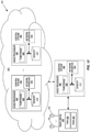
- the described embodiments may be implemented in any appropriate type of communication system supporting any suitable communication standards and using any suitable components. As one example, certain embodiments may be implemented in a communication system such as that illustrated in Figure 1 . Although certain embodiments are described with respect to LTE systems and related terminology, the disclosed concepts are not limited to LTE or a 3GPP system. Additionally, although reference may be made to the term "cell”, the described concepts may also apply in other contexts, such as beams used in Fifth Generation (5G) systems, for instance.
- 5G Fifth Generation
- a communication system 100 comprises a plurality of wireless communication devices 105 (e.g., UEs, machine type communication [MTC] / machine-to-machine [M2M] UEs) and a plurality of radio access nodes 110 (e.g., eNodeBs or other base stations).
- Communication system 100 is organized into cells 115, which are connected to a core network 120 via corresponding radio access nodes 110.
- Radio access nodes 110 are capable of communicating with wireless communication devices 105 along with any additional elements suitable to support communication between wireless communication devices or between a wireless communication device and another communication device (such as a landline telephone).
- wireless communication devices 105 may represent communication devices that include any suitable combination of hardware and/or software, these wireless communication devices may, in certain embodiments, represent devices such as those illustrated in greater detail by FIGS. 10A and 10B .
- the illustrated radio access node may represent network nodes that include any suitable combination of hardware and/or software, these nodes may, in particular embodiments, represent devices such those illustrated in greater detail by FIGS. 10A, 10B and 11A and 11B .
- a wireless communication device 200A comprises a processor 205 (e.g., Central Processing Units (CPUs), Application Specific Integrated Circuits (ASICs), Field Programmable Gate Arrays (FPGAs), and/or the like), a memory 210, a transceiver 215, and an antenna 220.
- processors 205 e.g., Central Processing Units (CPUs), Application Specific Integrated Circuits (ASICs), Field Programmable Gate Arrays (FPGAs), and/or the like
- a memory 210 e.g., Random Access to Access
- FPGAs Field Programmable Gate Arrays
- antenna 220 e.g., a wireless communication device 200A
- some or all of the functionality described as being provided by UEs, MTC or M2M devices, and/or any other types of wireless communication devices may be provided by the device processor executing instructions stored on a computer-readable medium, such as memory 210.
- Alternative embodiments may include additional components beyond those shown in Figure 2A that may be responsible for
- a wireless communication device 200B comprises at least one module 225 configured to perform one or more corresponding functions. Examples of such functions include various method steps or combinations of method steps as described herein with reference to wireless communication device(s).
- a module may comprise any suitable combination of software and/or hardware configured to perform the corresponding function. For instance, in some embodiments a module comprises software configured to perform a corresponding function when executed on an associated platform, such as that illustrated in Figure 10A .
- a radio access node 300A comprises a control system 320 that comprises a node processor 305 (e.g., CPUs, ASICs, FPGAs, and/or the like), memory 310, and a network interface 315.
- radio access node 300A comprises at least one radio unit 325 comprising at least one transmitter 335 and at least one receiver coupled to at least one antenna 330.
- radio unit 325 is external to control system 320 and connected to control system 320 via, e.g., a wired connection (e.g., an optical cable).
- radio unit 325 and potentially the antenna 330 are integrated together with control system 320.
- Node processor 305 operates to provide at least one function 345 of radio access node 300A as described herein.
- the function(s) are implemented in software that is stored, e.g., in the memory 310 and executed by node processor 305.
- radio access node 300 may comprise additional components to provide additional functionality, such as the functionality described herein and/or related supporting functionality.
- a radio access node 300B comprises at least one module 350 configured to perform one or more corresponding functions. Examples of such functions include various method steps or combinations of method steps as described herein with reference to radio access node(s).
- a module may comprise any suitable combination of software and/or hardware configured to perform the corresponding function. For instance, in some embodiments a module comprises software configured to perform a corresponding function when executed on an associated platform, such as that illustrated in Figure 11A .
- FIG. 12 is a block diagram that illustrates a virtualized radio access node 400 according to an embodiment of the disclosed subject matter.
- the concepts described in relation to Figure 12 may be similarly applied to other types of network nodes. Further, other types of network nodes may have similar virtualized architectures.
- the term "virtualized radio access node” refers to an implementation of a radio access node in which at least a portion of the functionality of the radio access node is implemented as a virtual component(s) (e.g., via a virtual machine(s) executing on a physical processing node(s) in a network(s)).
- radio access node 400 comprises control system 320 as described in relation to Figure 11A .
- Control system 320 is connected to one or more processing nodes 420 coupled to or included as part of a network(s) 425 via network interface 315.
- Each processing node 420 comprises one or more processors 405 (e.g., CPUs, ASICs, FPGAs, and/or the like), memory 410, and a network interface 415.
- functions 345 of radio access node 300A described herein are implemented at the one or more processing nodes 420 or distributed across control system 320 and the one or more processing nodes 420 in any desired manner.
- some or all of the functions 345 of radio access node 300A described herein are implemented as virtual components executed by one or more virtual machines implemented in a virtual environment(s) hosted by processing node(s) 420.
- additional signaling or communication between processing node(s) 420 and control system 320 is used in order to carry out at least some of the desired functions 345.
- control system 320 may be omitted, in which case the radio unit(s) 325 communicate directly with the processing node(s) 420 via an appropriate network interface(s).
- a computer program comprises instructions which, when executed by at least one processor, causes at least one processor to carry out the functionality of a radio access node (e.g., radio access node 110 or 300A) or another node (e.g., processing node 420) implementing one or more of the functions of the radio access node in a virtual environment according to any of the embodiments described herein.
- a radio access node e.g., radio access node 110 or 300A
- another node e.g., processing node 420
- Figures 13A-F illustrate methods of operating a wireless communication device according to embodiments of the disclosed subject matter.
- the methods could be performed by an apparatus such as that illustrated in any of FIGS. 9-12 , for instance. Additionally, the methods may be performed in conjunction with any of various alternative features as described above, such as various alternative time transmission interval configurations, subframe configurations, timing arrangements, signaling procedures, etc.
- the method comprises identifying multiple candidate start positions for uplink (UL) transmission in unlicensed spectrum (S1305), determining at step (S1310) if the starting positions will be based on autonomous UL starting points or fixed UL starting points. If autonomous UL starting points, determining at step (S1315) if the channel is obtained at subframe boundary. If yes, the UE transmits the whole TB on a full subframe (S1320). If no, UE punctures the TB (S1325), and only transmits partial subframe of the TB depending on LBT outcome. At (S1330), the UE retransmits the discarded part of the TB in later subframes or the whole TB in the last scheduled UL subframe with the same HARQ process ID as the punctured subframe.
- one bit in the UL grant indicates whether the UE is allowed to autonomously transmit after the scheduled UL subframes (S1345). If the bit allows autonomous transmission at the end, the UE shall transmit the discarded part of the TB if the UE does not transmit full first subframe (S1350). If the bit disallows autonomous transmission at the end, UE waits for full or partial retransmission to be scheduled by the eNB later (S1355).
- the eNB schedules X full subframes and part of a subframe, e.g., 1 ⁇ 2 of the subframe for UL transmission.
- the scheduling of a partial UL subframe is via signaling to the UE in a grant DCI that the UE shall stop UL transmission in said partial UL subframe at a UL stopping point earlier than the last OFDM symbol.
- step (S1360) determination is made if the UE transmit at full first subframe. If it does not (S1365), UE punctures the TB for first subframe, and autonomously retransmits the discarded part of the TB on the partial subframe scheduled at the end of the transmission burst using the same HARQ process ID as the punctured subframe.
- the UE transmits full first subframe (S1370), it transmits new data with a new HARQ process ID in one embodiment.
- the UE shall not transmit on the partial subframe scheduled if it transmits full first subframe.
- the TBS of the first subframe in the UL transmission burst is scaled down if it is a partial subframe transmission (S1380).
- TBS is indexed by MCS and ⁇ N PRB * ⁇ ⁇ , where ⁇ is the ratio of transmitted partial subframe to a full subframe and ⁇ x ⁇ is the floor function.
- the scaling factor may depend on the transmission starting point or may be semi-statically configured via higher layer signaling (such as radio resource control (RRC) signaling).
- RRC radio resource control
- the punctured transmission on the first subframe in a transmission burst is not considered as a reference subframe for Contention Window (CW) adjustment for LBT (S1385).
- the subframe after the punctured transmission in a transmission burst is used as a reference subframe for CW adjustment, regardless of whether the punctured transmission is used.
- the UE simply follows the UL grant for transmission (S1405). But the UE scales down the TBS of the first subframe in the UL transmission burst and for multi-subframe scheduling (S1410).
- the TBS of the first subframe in the UL transmission burst is scaled down for single subframe scheduling (S1420).
- the selecting may be performed in any of various alternative ways as described above in relation to FIGS. 6-8 , for instance.
- the performing of UL transmission may comprise e.g. transmitting information using defined resources as described above.
Description
- The disclosed subject matter relates generally to telecommunications. Certain embodiments relate more particularly to concepts such as Licensed-assisted access, Long Term Evolution (LTE) uplink transmissions and Contention Window (CW) adjustment.
- The 3GPP work on "Licensed-Assisted Access" (LAA) intends to allow Long Term Evolution (LTE) equipment to also operate in the unlicensed radio spectrum. Candidate bands for LTE operation in the unlicensed spectrum include 5 gigahertz (GHz), 3.5 GHz, etc. The unlicensed spectrum is used as a complement to the licensed spectrum or allows completely standalone operation.
- For the case of an unlicensed spectrum used as a complement to the licensed spectrum, devices connect in the licensed spectrum (primary cell or PCell) and use carrier aggregation to benefit from additional transmission capacity in the unlicensed spectrum (secondary cell or SCell). The carrier aggregation (CA) framework allows to aggregate two or more carriers with the condition that at least one carrier (or frequency channel) is in the licensed spectrum and at least one carrier is in the unlicensed spectrum. In the standalone (or completely unlicensed spectrum) mode of operation, one or more carriers are selected solely in the unlicensed spectrum.
- Regulatory requirements, however, may not permit transmissions in the unlicensed spectrum without prior channel sensing, transmission power limitations, or imposed maximum channel occupancy time. Since the unlicensed spectrum is generally shared with other radios of similar or dissimilar wireless technologies, a so called listen-before-talk (LBT) method needs to be applied. LBT involves sensing the medium for a pre-defined minimum amount of time and backing off if the channel is busy. Due to the centralized coordination and dependency of terminal devices on the base-station (eNB) for channel access in LTE operation and imposed LBT regulations, LTE uplink (UL) performance is especially hampered. UL transmission is becoming more and more important with user-centric applications and the need for pushing data to cloud.
- Today, the unlicensed 5 GHz spectrum is mainly used by equipment implementing the IEEE 802.11 Wireless Local Area Network (WLAN) standard. This standard is known under its marketing brand "Wi-Fi" and allows completely standalone operation in the unlicensed spectrum. Unlike the case in LTE, Wi-Fi terminals can asynchronously access the medium and thus show better UL performance characteristics especially in congested network conditions.
- LTE uses Orthogonal Frequency Division Multiplexing (OFDM) in the downlink and Discrete Fourier Transform (DFT)-spread OFDM (also referred to as single-carrier Frequency Division Multiple Access (FDMA)) in the uplink. The basic LTE downlink physical resource can thus be seen as a time-frequency grid as illustrated in
Figure 1 where each resource element corresponds to one OFDM subcarrier during one OFDM symbol interval. The uplink subframe has the same subcarrier spacing as the downlink and the same number of Single Carrier FDMA (SC-FDMA) symbols in the time domain as OFDM symbols in the downlink. - In the time domain, LTE downlink transmissions are organized into radio frames of 10 ms, each radio frame consisting of ten equally-sized subframes of length Tsubframe = 1 ms as shown in
Figure 2 . Each subframe comprises two slots of duration 0.5 ms each, and the slot numbering within a frame ranges from 0 to 19. For normal cyclic prefix, one subframe consists of 14 OFDM symbols. The duration of each symbol is approximately 71.4 µs. - Furthermore, the resource allocation in LTE is typically described in terms of resource blocks, where a resource block corresponds to one slot (0.5 ms) in the time domain and 12 contiguous subcarriers in the frequency domain. A pair of two adjacent resource blocks in time direction (1.0 ms) is known as a resource block pair. Resource blocks are numbered in the frequency domain, starting with 0 from one end of the system bandwidth.
- Downlink transmissions are dynamically scheduled, i.e., in each subframe the base station transmits control information about which terminals data is transmitted to and upon which resource blocks the data is transmitted, in the current downlink subframe. This control signaling is typically transmitted in the first 1, 2, 3 or 4 OFDM symbols in each subframe, and the number n = 1, 2, 3 or 4 is known as the Control Format Indicator (CFI). The downlink subframe also contains common reference symbols, which are known to the receiver and used for coherent demodulation of e.g. the control information. A downlink system with CFI = 3 OFDM symbols as control is illustrated in
Figure 3 . The reference symbols shown inFigure 3 are the cell specific reference symbols (CRS) and are used to support multiple functions including fine time and frequency synchronization and channel estimation for certain transmission modes. - Uplink transmissions are dynamically scheduled, i.e., in each downlink subframe the base station transmits control information about which terminals should transmit data to the eNB in subsequent subframes, and upon which resource blocks the data is transmitted. The uplink resource grid is comprised of data and uplink control information in the Physical Uplink Shared Channel (PUSCH), uplink control information in the Physical Uplink Control Channel (PUCCH), and various reference signals such as Demodulation Reference Signals (DMRS) and Sounding Reference Signals (SRS). DMRSs are used for coherent demodulation of PUSCH and PUCCH data, whereas SRSs are not associated with any data or control information but are generally used to estimate the uplink channel quality for purposes of frequency-selective scheduling. An example uplink subframe is shown in
Figure 4 . Note that UL DMRS and SRS are time-multiplexed into the UL subframe, and SRS are always transmitted in the last symbol of a normal UL subframe. The PUSCH DMRS is transmitted once every slot for subframes with normal cyclic prefix, and is located in the fourth and eleventh SC-FDMA symbols. - From LTE Rel-11 onwards, DL or UL resource assignments can also be scheduled on the enhanced Physical Downlink Control Channel (EPDCCH). For Rel-8 to Rel-10 only the Physical Downlink Control Channel (PDCCH) is available. Resource grants are UE specific and are indicated by scrambling the Downlink Control Information (DCI) Cyclic Redundancy Check (CRC) with the User Equipment (UE)-specific Cell Radio Network Temporary Identifier (C-RNTI). A unique C-RNTI is assigned by a cell to every UE associated with it, and can take values in the range 0001-FFF3 in hexadecimal format. A UE uses the same C-RNTI on all serving cells.
- In LTE the uplink access is typically controlled by eNB, i.e., scheduled. In this case the UE would report to the eNB when data is available to be transmitted, e.g., by sending a scheduling request message (SR). Based on this, the eNB would grant the resources and relevant information to the UE in order to carry out the transmission of a certain size of data. The assigned resources are not necessarily sufficient for the UE to transmit all the available data. Therefore, it is possible that the UE sends a buffer status report (BSR) control message in the granted resources, in order to inform the eNB about the correct size and updated size of the data waiting for transmission. Based on that, the eNB would further grant the resources to carry on with the UE uplink transmission of the corrected size of data.
- In more detail, every time new data arrives at the UE's empty buffer, the following procedure should be performed:
- a. Using Physical Uplink Control Channel (PUCCH), the UE informs the network that it needs to transmit data by sending a Scheduling Request (SR) indicating that it needs uplink access. UE has aperiodic timeslots for SR transmissions (typically on a 5, 10, or 20 ms interval).
- b. Once the eNB receives the SR request bit, it responds with a small "uplink grant" that is just large enough to communicate the size of the pending buffer. The reaction to this request typically takes 3ms.
- c. After the UE receives and processes (takes about 3 ms) its first uplink grant, it typically sends a Buffer Status Report (BSR) that is a Medium Access Control (MAC) Control Element (MAC CE) used to provide information about the amount of pending data in the uplink buffer of the UE. If the grant is big enough, the UE sends data from its buffer within this transmission as well. Whether the BSR is sent depends also on conditions specified in 3GPP TS 36.321.
- d. The eNB receives the BSR message, allocates the necessary uplink resources and sends back another uplink grant that will allow the device to drain its buffer.
- Adding it all up, about 16 ms (+time to wait for PUCCH transmission opportunity) of delay can be expected between data arrival at the empty buffer in the UE and reception of this data in the eNB.
- In case the UE is not Radio Resource Control (RRC) connected in LTE or lost its uplink synchronization since it did not transmit or receive anything for a certain time, the UE would use the random access procedure to connect to the network, obtain synchronization and also send the SR. If this is the case, the procedure until the data can be sent would take even longer than the SR transmission on PUCCH.
- In the LTE system, the transmission formats and parameters are controlled by the eNB. Such downlink control information (DCI) typically contains:
- Resources allocated for UL transmission (including whether frequency hopping is applied).
- Modulation and coding scheme
- Redundancy versions
- New data indicator
- Transmit power control command
- Information about demodulation reference symbol (DMRS)
- In case of cross-carrier scheduling, the target carrier index is also included.
- Other applicable control information on UL transmissions
- The DCI is first protected by 16-bit CRC. The CRC bits are further scrambled by the UE assigned identity (C-RNTI). The DCI and scrambled CRC bits are further protected by convolutional coding. The encoded bits are transmitted from the eNB to UE using either PDCCH or EPDCCH.
- If the UE transmits transmissions using a
Type 1 channel access procedure that are associated with channel access priority class p on a carrier, the UE maintains the contention window value CWp and adjusts CWp for those transmissions, using the following procedure: - If the New Data Indicator (NDI) value for at least one Hybrid Automatic Repeat Request (HARQ) process associated with HARQ_ID_ref is toggled,
- For every priority class p ∈ {1,2,3,4} set CWp = CWmin,p
- Otherwise, increase CWp for every priority class p ∈ {1,2,3,4} to the next higher allowed value;
HARQ_ID_ref is the HARQ process ID of UL-SCH in reference subframe nref. The reference subframe nref is determined as follows: - If the UE receives an UL grant in subframe ng , subframe nw is the most recent subframe before subframe ng - 3 in which the UE has transmitted UL-
SCH using Type 1 channel access procedure. - If the UE transmits transmissions including UL-SCH without gaps starting with subframe n 0 and in subframes n 0,n 1,Λ ,nw , reference subframe nref is subframe n 0,
- Otherwise, reference subframe nref is subframe nw ,
- Up to now, the spectrum used by LTE is dedicated to LTE. This has the advantage that LTE system does not need to care about the coexistence issue and the spectrum efficiency can be maximized. However, the spectrum allocated to LTE is limited which cannot meet the ever increasing demand for larger throughput from applications/services. Therefore, Rel-13 Licensed-assisted access (LAA) extended LTE to exploit unlicensed spectrum is required in addition to licensed spectrum. Unlicensed spectrum can, by definition, be simultaneously used by multiple different technologies. Therefore, LTE needs to consider the coexistence issue with other systems such as IEEE 802.11 (Wi-Fi). Operating LTE in the same manner in unlicensed spectrum as in licensed spectrum can seriously degrade the performance of Wi-Fi, as Wi-Fi will not transmit once it detects the channel is occupied.
- Furthermore, one way to utilize the unlicensed spectrum reliably is to transmit essential control signals and channels on a licensed carrier. That is, as shown in
Figure 5 , a UE is connected to a PCell in the licensed band and one or more SCells in the unlicensed band. In this application we denote a secondary cell in unlicensed spectrum as licensed-assisted access secondary cell (LAA SCell). In the case of standalone operation as in MulteFire, no licensed cell is available for uplink control signal transmissions. -
WO 2017/049560 A1 discloses a user equipment and a wireless communication method for LAA. The user equipment comprises a receiver operative to receive a UL grant which schedules a subframe for UL transmission, a first circuit operative to perform LBT, a transmitter operative to transmit a PUSCH in the scheduled subframe starting from one available starting position of multiple candidate starting positions in the scheduled subframe if the LBT is successful. According to the document, it is possible to increase the possibility that PUSCH could be sent in the scheduled subframe after LBT. -
US 2017/041805 A1 discloses a mobile device obtaining data to be wirelessly transmitted over a shared spectrum in an uplink channel to a base station. The uplink channel is formatted with a frame/subframe structure with a predetermined timing. The mobile device determines whether the shared spectrum is free for transmission according to a Listen Before Transmit procedure. When the shared spectrum is free for transmission, the mobile device selects a start time in the uplink channel that mitigates interference from other mobile devices in proximity to the mobile device. Beginning at the start time, the mobile device transmits the data over the shared spectrum in the uplink channel to the base station. - Intel Corporation: "On the multiple uplink starting and ending positions for FS3", 3GPP Draft; R1-1704682, discusses about the support for multiple starting and ending positions in a subframe for UL on an LAA SCell and various related issues, such as DMRS transmission and TBS selection.
- The invention is defined by the independent claims. Advantageous embodiments are defined in the dependent claims.
- Systems and method for multiple uplink starting positions are disclosed. In some embodiments, a method of operating a wireless communication device includes identifying candidate starting positions for an uplink (UL) transmission in an unlicensed spectrum and selecting at least one starting position from among the candidate start positions based on autonomous UL starting points according to an outcome of a listen-before-talk (LBT) procedure performed with respect to the unlicensed spectrum and/or one or more fixed UL starting points signaled in an UL grant. In this way, a wireless communication device may improve throughput by using resources that would not have been available otherwise.
- In some embodiments, selecting the at least one starting position is based on autonomous UL starting points, and the method also includes, if a channel is obtained at a subframe boundary, transmitting a whole transport block (TB) on a full subframe.
- In some embodiments, selecting the at least one starting position is based on autonomous UL starting points, and the method also includes, if a channel is not obtained at a subframe boundary, puncturing a TB and transmitting a partial subframe depending on LBT outcome.
- In some embodiments, the method also includes retransmitting the discarded part of the TB in the last scheduled uplink subframe using the same HARQ process ID as the punctured subframe. In some embodiments, the method also includes retransmitting a whole TB in the last scheduled uplink subframe using the same HARQ process ID as the punctured subframe.
- In some embodiments, the method also includes retransmitting autonomously the discarded part of the TB in the next subframe after the scheduled uplink subframes. In some embodiments, the method also includes retransmitting autonomously the whole TB in the next subframe after scheduled uplink subframes.
- In some embodiments, the method also includes obtaining an UL grant from an eNB; and determining if the wireless communication device is allowed to autonomously transmit after scheduled uplink subframe based on the UL grant from the eNB.
- In some embodiments, where the wireless communication device is allowed to autonomously transmit after scheduled uplink subframe, the method also includes transmitting the discarded part of the TB, if the wireless communication device does not transmit a full first subframe. In some embodiments, where the wireless communication device is not allowed to autonomously transmit after scheduled uplink subframe, the method also includes waiting for a full or partial subframe retransmission schedule.
- In some embodiments, the method also includes obtaining a scheduling decision of X subframes followed by a predetermined partial or full subframe. In some embodiments, the scheduling of a partial UL subframe is received by the wireless communication device in a grant indicating that the wireless communication device shall stop UL transmission in the partial UL subframe at a UL ending point earlier than the last symbol.
- In some embodiments, where the wireless communication device does not transmit full first subframe, the method also includes puncturing the TB for first subframe; and retransmitting the discarded part of TB or the full TB on the predetermined subframe scheduled at the end of transmission burst using same HARQ process ID as the punctured subframe.
- In some embodiments, where the wireless communication device transmits a full first subframe, the method also includes transmitting with a different HARQ process ID in the predetermined subframe as compared to the full first subframe.
- In some embodiments, where the wireless communication device transmits on full first subframe, the method also includes refraining from transmitting on the predetermined partial or full subframe.
- In some embodiments, the method also includes scaling down the Transport Block Size (TBS) of a first subframe if it is a partial subframe transmission. In some embodiments, scaling down the TBS of the first subframe comprises determining the TBS of the first subframe based on └ NPRB ∗ α ┘, where α is the ratio of transmitted partial subframe to a full subframe and └ x ┘ is the floor function. In some embodiments, = 1/2 .
- In some embodiments, the method also includes considering the subframe after the punctured transmission in a transmission burst as a reference subframe for contention window adjustment for LBT.
- In some embodiments, the starting position is based on a fixed UL starting point, and the method also includes following an UL grant for communication. In some embodiments, the method also includes scaling down the TBS for a first subframe in the uplink transmission burst and for multi-subframe scheduling. In some embodiments, scaling down the TBS of the first subframe comprises determining the TBS of the first subframe based on └ NPRB * α ┘, where α is the ratio of transmitted partial subframe to a full subframe and └ x ┘ is the floor function. In some embodiments, α = 1/2 .
- In some embodiments, the method also includes receiving two TBS/MCS signaled in the UL grant, one used for a partial subframe transmission and another for full subframe transmissions within the scheduled subframes.
- In some embodiments, the method includes scaling down the TBS of a first subframe in an uplink transmission burst for a single subframe scheduling.
- In certain embodiments of the disclosed subject matter, detailed design and UE behavior are provided for supporting multiple starting positions for UL transmission on unlicensed spectrum considering autonomous UL starting points based on LBT, and fixed UL starting points signaled in UL grant.
- In a first option, the UE punctures the Transport Block (TB) to transmit partial subframe depending on LBT outcome. The UE can discard the remaining part of the TB or retransmit the discarded part of the TB in later subframes. In a second option the UE simply follows UL grant for transmission. But it scales down the TB size (TBS) for the first subframe of a transmission burst if UE cannot transmit full subframe due to LBT failure at subframe boundary.
- Certain embodiments can be applied to LAA/NR-U/MulteFire or other technologies operating UL transmission on unlicensed spectrum.
- Certain embodiments are presented in recognition of shortcomings associated with conventional techniques and technologies, such as the following examples. Approaches have been considered to support multiple starting positions for UL transmission on unlicensed spectrum, such as autonomous UL starting points based on LBT, and fixed UL starting points signaled in UL grant. Unfortunately, the detailed design and UE behavior are not set for these approaches.
- Certain embodiments may provide potential benefits compared to conventional techniques and technologies, such as the following examples.
- Support of multiple starting positions for flexible and efficient channel access on unlicensed spectrum
- Reduce UL transmission delay and increase the overall system performance
- Enable efficient UL scheduling and transmission when multiple starting/ending positions is supported.
- The accompanying drawing figures incorporated in and forming a part of this specification illustrate several aspects of the disclosure, and together with the description serve to explain the principles of the disclosure.
-
Figure 1 illustrates an Long Term Evolution (LTE) downlink physical resource; -
Figure 2 illustrates an LTE time-domain structure; -
Figure 3 illustrates a downlink subframe; -
Figure 4 illustrates an uplink subframe; -
Figure 5 illustrates licensed-assisted access (LAA) to unlicensed spectrum using LTE carrier aggregation; -
Figure 6 illustrates multiple starting positions for UL, according to some embodiments of the current disclosure; -
Figure 7 illustrates a retransmission of punctured transmission within same UL burst, according to some embodiments of the current disclosure; -
Figure 8 illustrates a retransmission of punctured transmission after the scheduled UL burst, according to some embodiments of the current disclosure; -
Figure 9 illustrates a communication system according to an embodiment of the disclosed subject matter, according to some embodiments of the current disclosure; -
Figure 10A illustrates a wireless communication device according to an embodiment of the disclosed subject matter, according to some embodiments of the current disclosure; -
Figure 10B illustrates a wireless communication device according to another embodiment of the disclosed subject matter, according to some embodiments of the current disclosure; -
Figure 11A illustrates a radio access node according to an embodiment of the disclosed subject matter, according to some embodiments of the current disclosure; -
Figure 11B illustrates a radio access node according to another embodiment of the disclosed subject matter, according to some embodiments of the current disclosure; -
Figure 12 illustrates a radio access node according to yet another embodiment of the disclosed subject matter, according to some embodiments of the current disclosure; -
Figures 13A-F illustrate methods of operating a wireless communication device according to embodiments of the disclosed subject matter, according to some embodiments of the current disclosure; -
Figures 14A-C illustrates a method of operating a wireless communication device according to another embodiment of the disclosed subject matter, according to some embodiments of the current disclosure. - The embodiments set forth below represent information to enable those skilled in the art to practice the embodiments and illustrate the best mode of practicing the embodiments. Upon reading the following description in light of the accompanying drawing figures, those skilled in the art will understand the concepts of the disclosure and will recognize applications of these concepts not particularly addressed herein. It should be understood that these concepts and applications fall within the scope of the disclosure.
- Thus the disclosed subject matter provides, among other things, methods to support multiple starting positions for scheduled UL transmission on unlicensed spectrum for both autonomous and fixed UL starting points.
- The description below assumes LAA operation as an example. However, the methods disclosed herein can also be applied to LAA/NR-U/ MulteFire or other technologies operating scheduled UL transmission on unlicensed spectrum.
- In one embodiment, multiple starting positions can be configured via RRC signaling for a UE. The UE starts UL transmission at one of the multiple starting positions depending on when it gets the channel.
- Note that while the term "subframe" is used for LAA/LTE, in 5G, the term "slot" may be used. Thus, while the discussion below focuses on LAA and therefore uses the terms "subframe," it is to be understood that the same concepts apply to 5G in Unlicensed Spectrum (5G-U) but where the term "slot" is used in place of "subframe." Thus, the term "subframe/slot" is used to generally refer to either a subframe or a slot.
- In a first embodiment, if the UE gets the channel at subframe boundary, it transmits the whole TB on a full subframe; if the UE gets the channel at one of the other starting points, it punctures the TB and only transmits part of the TB based on the available resources. For example, in
Figure 6 where two starting points defined, if UE gets the channel atsymbol # 7, it punctures the TB to only transmit the second half of the TB starting fromsymbol # 7. - As an alternative, if the UE punctures the TB and transmits part of the TB in the first transmission and discards the remaining part, it shall retransmit the discarded part of the TB or the whole TB in the last scheduled UL subframe. The last subframe in the scheduled UL burst, follows the same HARQ ID as the punctured subframe,
Figure 7 shows an example. eNB receives two transmissions for the same TB and combines them for decoding. - In a second embodiment, if the UE punctures the TB and transmits part of the TB in the first transmission and discards the remaining part, it shall autonomously retransmit the discarded part of the TB or the whole TB after the scheduled UL subframes. This is shown in
Figure 8 . The eNB receives two transmissions for the same TB and combines them for decoding. - In a third embodiment, one bit in the UL grant indicates whether the UE is allowed to autonomously transmit after the scheduled UL subframes. If the bit allows autonomous transmission at the end, the UE shall transmit the discarded part of the TB if the UE does not transmit full first subframe. If the bit disallows autonomous transmission at the end, a full retransmission will be scheduled by the eNB later.
- In a fourth embodiment, the eNB schedules X full subframes and part of a subframe, e.g., ½ of the subframe for UL transmission. The scheduling of a partial UL subframe is via signaling to the UE in a grant DCI that the UE shall stop UL transmission in said partial UL subframe at a UL stopping point earlier than the last OFDM symbol.
- Then if the UE does not transmit full first subframe and punctures the TB for first subframe, it shall autonomously transmit the discarded part of the TB on the partial subframe scheduled in the end of the transmission burst using the same HARQ process ID.
- If the UE transmits full first subframe, it shall transmit new data with a new HARQ process ID in one embodiment. In a second embodiment, the UE shall not transmit on the partial subframe scheduled in the end if it transmits full first subframe.
- In a fifth embodiment, the TBS of the first subframe in the UL transmission burst is always scaled down. For example, TBS is indexed by MCS and └ NPRB * α ┘, where α is the ratio of transmitted partial subframe to a full subframe and └ x ┘ is the floor function. The scaling factor may depend on the transmission starting point or may be semi-statically configured via higher layer signaling (such as radio resource control (RRC) signaling).
- The UE uses the IMCS to read a ITBS indice from a table providing Modulation, TBS index and redundancy version table for PUSCH. It then uses the ITBS and the allocated PRB size NPRB to read the TBS from a table providing Transport block size (dimension 27×110).
- A α factor is then applied to reduce the value of NPRB and then use the adjusted down index to read from the table providing Transport block size.
- For LAA UL, NPRB is always a multiple of 10. In the present embodiment, α = 1/2 is used. So the adjusted value will still be an integer. However, the TBS is determined with an adjusted value based on └ α · N PRB┘, where └ x ┘ is the floor function.
- In a sixth embodiment, the punctured transmission on the first subframe in a transmission burst is not considered as a reference subframe for Contention Window (CW) adjustment for LBT.
- In another embodiment, the reference subframe nref is determined as follows:
- If the UE receives an UL grant in subframe ng , subframe nw is the most recent subframe before subframe ng - 3 in which the UE has transmitted UL-
SCH using Type 1 channel access procedure. - If the UE transmits transmissions including UL-SCH without gaps starting with non-punctured subframe n 0 and in subframes n 0,n 1,Λ ,nw , reference subframe nref is subframe n 0 ,
- If the UE transmits transmissions including UL-SCH without gaps starting with punctured subframe n 0 and in subframes n 0,n 1,Λ ,nw , reference subframe nref is subframe n 1,
- otherwise,
- if nw is non-punctured, reference subframe nref is subframe nw ,
- otherwise, nref is kept the same as the last scheduled transmission.
- Multiple starting positions can be configured via RRC signaling for a UE. The starting position for a scheduled UL subframe is signaled to the UE in UL grant.
- In one embodiment, the TBS of the first subframe in the UL transmission burst is scaled down for multi-subframe scheduling. For example, TBS is indexed by MCS and └ NPRB * α ┘ for the first subframe, where α is the ratio of partial subframe to a full subframe.
- In another embodiment, one field is added to signal TBS/MCS for the first subframe in UL grant for multi-subframe scheduling.
- In another embodiment, the TBS of the first subframe in the UL transmission burst is scaled down for single subframe scheduling.
- The described embodiments may be implemented in any appropriate type of communication system supporting any suitable communication standards and using any suitable components. As one example, certain embodiments may be implemented in a communication system such as that illustrated in
Figure 1 . Although certain embodiments are described with respect to LTE systems and related terminology, the disclosed concepts are not limited to LTE or a 3GPP system. Additionally, although reference may be made to the term "cell", the described concepts may also apply in other contexts, such as beams used in Fifth Generation (5G) systems, for instance. - Referring to
Figure 9 , acommunication system 100 comprises a plurality of wireless communication devices 105 (e.g., UEs, machine type communication [MTC] / machine-to-machine [M2M] UEs) and a plurality of radio access nodes 110 (e.g., eNodeBs or other base stations).Communication system 100 is organized intocells 115, which are connected to acore network 120 via correspondingradio access nodes 110.Radio access nodes 110 are capable of communicating withwireless communication devices 105 along with any additional elements suitable to support communication between wireless communication devices or between a wireless communication device and another communication device (such as a landline telephone). - Although
wireless communication devices 105 may represent communication devices that include any suitable combination of hardware and/or software, these wireless communication devices may, in certain embodiments, represent devices such as those illustrated in greater detail byFIGS. 10A and 10B . Similarly, although the illustrated radio access node may represent network nodes that include any suitable combination of hardware and/or software, these nodes may, in particular embodiments, represent devices such those illustrated in greater detail byFIGS. 10A, 10B and11A and 11B . - Referring to
Figure 10A , awireless communication device 200A comprises a processor 205 (e.g., Central Processing Units (CPUs), Application Specific Integrated Circuits (ASICs), Field Programmable Gate Arrays (FPGAs), and/or the like), amemory 210, atransceiver 215, and anantenna 220. In certain embodiments, some or all of the functionality described as being provided by UEs, MTC or M2M devices, and/or any other types of wireless communication devices may be provided by the device processor executing instructions stored on a computer-readable medium, such asmemory 210. Alternative embodiments may include additional components beyond those shown in Figure 2A that may be responsible for providing certain aspects of the device's functionality, including any of the functionality described herein. - Referring to
Figure 10B , awireless communication device 200B comprises at least onemodule 225 configured to perform one or more corresponding functions. Examples of such functions include various method steps or combinations of method steps as described herein with reference to wireless communication device(s). In general, a module may comprise any suitable combination of software and/or hardware configured to perform the corresponding function. For instance, in some embodiments a module comprises software configured to perform a corresponding function when executed on an associated platform, such as that illustrated inFigure 10A . - Referring to
Figure 11A , aradio access node 300A comprises acontrol system 320 that comprises a node processor 305 (e.g., CPUs, ASICs, FPGAs, and/or the like),memory 310, and anetwork interface 315. In addition,radio access node 300A comprises at least oneradio unit 325 comprising at least onetransmitter 335 and at least one receiver coupled to at least oneantenna 330. In some embodiments,radio unit 325 is external to controlsystem 320 and connected to controlsystem 320 via, e.g., a wired connection (e.g., an optical cable). However, in some other embodiments,radio unit 325 and potentially theantenna 330 are integrated together withcontrol system 320.Node processor 305 operates to provide at least onefunction 345 ofradio access node 300A as described herein. In some embodiments, the function(s) are implemented in software that is stored, e.g., in thememory 310 and executed bynode processor 305. - In certain embodiments, some, or all of the functionality described as being provided by a base station, a node B, an enodeB, and/or any other type of network node may be provided by
node processor 305 executing instructions stored on a computer-readable medium, such asmemory 310 shown inFigure 11A . Alternative embodiments of radio access node 300 may comprise additional components to provide additional functionality, such as the functionality described herein and/or related supporting functionality. - Referring to
Figure 11B , aradio access node 300B comprises at least onemodule 350 configured to perform one or more corresponding functions. Examples of such functions include various method steps or combinations of method steps as described herein with reference to radio access node(s). In general, a module may comprise any suitable combination of software and/or hardware configured to perform the corresponding function. For instance, in some embodiments a module comprises software configured to perform a corresponding function when executed on an associated platform, such as that illustrated inFigure 11A . -
Figure 12 is a block diagram that illustrates a virtualizedradio access node 400 according to an embodiment of the disclosed subject matter. The concepts described in relation toFigure 12 may be similarly applied to other types of network nodes. Further, other types of network nodes may have similar virtualized architectures. As used herein, the term "virtualized radio access node" refers to an implementation of a radio access node in which at least a portion of the functionality of the radio access node is implemented as a virtual component(s) (e.g., via a virtual machine(s) executing on a physical processing node(s) in a network(s)). - Referring to
Figure 12 ,radio access node 400 comprisescontrol system 320 as described in relation toFigure 11A . -
Control system 320 is connected to one ormore processing nodes 420 coupled to or included as part of a network(s) 425 vianetwork interface 315. Eachprocessing node 420 comprises one or more processors 405 (e.g., CPUs, ASICs, FPGAs, and/or the like),memory 410, and anetwork interface 415. - In this example, functions 345 of
radio access node 300A described herein are implemented at the one ormore processing nodes 420 or distributed acrosscontrol system 320 and the one ormore processing nodes 420 in any desired manner. In some embodiments, some or all of thefunctions 345 ofradio access node 300A described herein are implemented as virtual components executed by one or more virtual machines implemented in a virtual environment(s) hosted by processing node(s) 420. As will be appreciated by one of ordinary skill in the art, additional signaling or communication between processing node(s) 420 andcontrol system 320 is used in order to carry out at least some of the desired functions 345. As indicated by dotted lines, in some embodiments controlsystem 320 may be omitted, in which case the radio unit(s) 325 communicate directly with the processing node(s) 420 via an appropriate network interface(s). - In some embodiments, a computer program comprises instructions which, when executed by at least one processor, causes at least one processor to carry out the functionality of a radio access node (e.g.,
radio access node -
Figures 13A-F illustrate methods of operating a wireless communication device according to embodiments of the disclosed subject matter. The methods could be performed by an apparatus such as that illustrated in any ofFIGS. 9-12 , for instance. Additionally, the methods may be performed in conjunction with any of various alternative features as described above, such as various alternative time transmission interval configurations, subframe configurations, timing arrangements, signaling procedures, etc. - Referring to
Figure 13A , the method comprises identifying multiple candidate start positions for uplink (UL) transmission in unlicensed spectrum (S1305), determining at step (S1310) if the starting positions will be based on autonomous UL starting points or fixed UL starting points. If autonomous UL starting points, determining at step (S1315) if the channel is obtained at subframe boundary. If yes, the UE transmits the whole TB on a full subframe (S1320). If no, UE punctures the TB (S1325), and only transmits partial subframe of the TB depending on LBT outcome. At (S1330), the UE retransmits the discarded part of the TB in later subframes or the whole TB in the last scheduled UL subframe with the same HARQ process ID as the punctured subframe. - In
Figure 13B , as an alternative to the steps ofFigure 13A , if the UE punctures the TB and transmits partial subframe of the TB depending on LBT outcome (S1335), UE retransmit autonomously the discarded part of the TB or the whole TB after the scheduled UL subframes (S1340). - In
Figure 13C , one bit in the UL grant indicates whether the UE is allowed to autonomously transmit after the scheduled UL subframes (S1345). If the bit allows autonomous transmission at the end, the UE shall transmit the discarded part of the TB if the UE does not transmit full first subframe (S1350). If the bit disallows autonomous transmission at the end, UE waits for full or partial retransmission to be scheduled by the eNB later (S1355). - In
Figure 13D , we described above that the eNB schedules X full subframes and part of a subframe, e.g., ½ of the subframe for UL transmission. The scheduling of a partial UL subframe is via signaling to the UE in a grant DCI that the UE shall stop UL transmission in said partial UL subframe at a UL stopping point earlier than the last OFDM symbol. - Then, at step (S1360) determination is made if the UE transmit at full first subframe. If it does not (S1365), UE punctures the TB for first subframe, and autonomously retransmits the discarded part of the TB on the partial subframe scheduled at the end of the transmission burst using the same HARQ process ID as the punctured subframe.
- If the UE transmits full first subframe (S1370), it transmits new data with a new HARQ process ID in one embodiment. As a further alternative (S1375), the UE shall not transmit on the partial subframe scheduled if it transmits full first subframe.
- In
Figure 13E , the TBS of the first subframe in the UL transmission burst is scaled down if it is a partial subframe transmission (S1380). As indicated above, TBS is indexed by MCS and └ NPRB * α ┘, where α is the ratio of transmitted partial subframe to a full subframe and └ x ┘ is the floor function. The scaling factor may depend on the transmission starting point or may be semi-statically configured via higher layer signaling (such as radio resource control (RRC) signaling). - In
Figure 13F , the punctured transmission on the first subframe in a transmission burst is not considered as a reference subframe for Contention Window (CW) adjustment for LBT (S1385). In some embodiments, the subframe after the punctured transmission in a transmission burst is used as a reference subframe for CW adjustment, regardless of whether the punctured transmission is used. - Referring to
Figure 14A , if at step (S1310) ofFigure 13A , the starting positions are based on fixed UL starting points, the UE simply follows the UL grant for transmission (S1405). But the UE scales down the TBS of the first subframe in the UL transmission burst and for multi-subframe scheduling (S1410). - In
Figure 14B , two transport block size (TBS)/MCS are signaled in the UL grant, one used for a partial subframe transmission and another for full subframe transmissions within the scheduled subframes (S1415). - In
Figure 14C , the TBS of the first subframe in the UL transmission burst is scaled down for single subframe scheduling (S1420). - The selecting may be performed in any of various alternative ways as described above in relation to
FIGS. 6-8 , for instance. The performing of UL transmission may comprise e.g. transmitting information using defined resources as described above. - At least some of the following abbreviations may be used in this disclosure. If there is an inconsistency between abbreviations, preference should be given to how it is used above. If listed multiple times below, the first listing should be preferred over any subsequent listing(s).
• BSR Buffer Status Request • CC Component Carrier • CCA Clear Channel Assessment • CQI Channel Quality Information • CRC Cyclic Redundancy Check • DCI Downlink Control Information • DL Downlink • DMTC DRS Measurement Timing Configuration • DRS Discovery Reference Signal • eNB evolved NodeB, base station • UE User Equipment • UL Uplink • LAA Licensed-Assisted Access • SCell Secondary Cell • STA Station • LBT Listen-before-talk • LTE-U LTE in Unlicensed Spectrum • PDCCH Physical Downlink Control Channel • PMI Precoding Matrix Indicator • PUSCH Physical Uplink Shared Channel • RAT Radio Access Technology • RNTI Radio Network Temporary Identifier • TB Transport Block • TBS Transport Block Size • TXOP Transmission Opportunity • UL Uplink • sTTI Shortened TTI
Claims (15)
- A method of operating a wireless communication device, comprising:identifying (S1305) a plurality of candidate starting positions for an uplink, UL, transmission in an unlicensed spectrum;selecting (S1310) at least one starting position from among the plurality of candidate starting positions based on autonomous UL starting points according to an outcome of a listen-before-talk, LBT, procedure performed with respect to the unlicensed spectrum;if a channel is not obtained at a subframe/slot boundary but is obtained at one of the other starting positions depending on the LBT outcome, puncturing (S1325, S1335) a whole transport block, TB, otherwise intended for said subframe/slot and transmitting only a part of said TB based on the available resources in a partial subframe/slot ; anddiscarding a remaining part of said TB or retransmitting the remaining part of the TB in one of later subframes/slots.
- The method of claim 1, further comprising:
if the channel is obtained at the subframe/slot boundary, transmitting (S1320) the whole TB on a full subframe/slot. - The method of claim 1, further comprising:retransmitting (S1330) the discarded part of the TB in a last scheduled uplink subframe/slot using a same Hybrid Automatic Repeat Request, HARQ, process ID as the punctured subframe/slot; orfurther comprising:
retransmitting (S1330) the whole TB in a last scheduled uplink subframe/slot using a same Hybrid Automatic Repeat Request, HARQ, process ID as the punctured subframe/slot. - The method of claim 1, further comprising:retransmitting (S1340) autonomously the discarded part of the TB in a next subframe/slot after scheduled uplink subframe/slots; orfurther comprising:
retransmitting (S1340) autonomously the whole TB in a next subframe/slot after scheduled uplink subframe/slots. - The method of any of claims 1 to 4, further comprising:obtaining a UL grant from a base station, eNB; anddetermining (S1345) if the wireless communication device is allowed to autonomously transmit after the scheduled uplink subframe/slot based on the UL grant from the eNB.
- The method of claim 5, wherein the wireless communication device is allowed to autonomously transmit after the scheduled uplink subframe/slot, the method further comprising:transmitting (S1350) the discarded part of the TB, if the wireless communication device does not transmit a full first subframe/slot; orwherein the wireless communication device is not allowed to autonomously transmit after the scheduled uplink subframe/slot, the method further comprising:
waiting (S1355) for a full or partial subframe/slot retransmission schedule. - The method of claim 1, further comprising:
obtaining a scheduling decision of X subframe/slots followed by a predetermined partial or full subframe/slot. - The method of claim 7, wherein the scheduling of a partial UL subframe/slot is received by the wireless communication device in a grant indicating that the wireless communication device shall stop UL transmission in the partial UL subframe/slot at a UL ending point earlier than the last symbol; or
wherein the wireless communication device does not transmit a full first subframe/slot, the method further comprises:puncturing (S1365) the TB for first subframe/slot; andretransmitting (S1365) the discarded part of TB or the full TB on the predetermined subframe/slot scheduled at the end of transmission burst using same HARQ process ID as the punctured subframe/slot. - The method of claim 7, wherein the wireless communication device transmits a full first subframe/slot, the method further comprising:transmitting (S1370) with a different Hybrid Automatic Repeat Request, HARQ, process ID in the predetermined subframe/slot as compared to the full first subframe/slot; orwherein the wireless communication device transmits on a full first subframe/slot, the method further comprising:
refraining (S1375) from transmitting on the predetermined partial or full subframe/slot. - The method of claim 1, further comprising:scaling (S1380) down a Transport Block Size, TBS, of a first subframe/slot if it is a partial subframe/slot transmission,wherein scaling down the TBS of the first subframe/slot comprises determining the TBS of the first subframe/slot based on └ NPRB ∗ α ┘, where α is a ratio of a transmitted partial subframe/slot to a full subframe/slot and └ x ┘ is a floor function.
- The method of any of claims 1 to 10, further comprising:
considering a subframe/slot after a punctured transmission in a transmission burst as a reference subframe/slot for contention window adjustment for LBT. - A wireless communication device adapted to:identify a plurality of candidate starting positions for an uplink, UL, transmission in an unlicensed spectrum;select at least one starting position from among the plurality of candidate starting positions based on autonomous UL starting points according to an outcome of a listen-before-talk, LBT, procedure performed with respect to the unlicensed spectrum;if a channel is not obtained at a subframe/slot boundary but is obtained at one of the other starting positions depending on the LBT outcome, puncture a whole transport block, TB, otherwise intended for said subframe/slot and transmit only a part of said TB based on the available resources in a partial subframe/slot ; anddiscard a remaining part of said TB or retransmit the remaining part of the TB in one of later subframes/slots.
- The wireless communication device of claim 12, wherein the wireless communication device is further adapted to perform the method of any one of claims 2 to 11.
- A computer program comprising instructions which, when executed on at least one processor of a wireless communication device, cause the at least one processor to carry out the method according to any one of claims 1 to 11.
- A carrier containing the computer program of claim 14, wherein the carrier is one of an electronic signal, an optical signal, a radio signal, or a computer readable storage medium.
Applications Claiming Priority (2)
| Application Number | Priority Date | Filing Date | Title |
|---|---|---|---|
| US201762491399P | 2017-04-28 | 2017-04-28 | |
| PCT/IB2018/052949 WO2018198092A1 (en) | 2017-04-28 | 2018-04-27 | Multiple starting positions for uplink transmission on unlicensed spectrum |
Publications (2)
| Publication Number | Publication Date |
|---|---|
| EP3616450A1 EP3616450A1 (en) | 2020-03-04 |
| EP3616450B1 true EP3616450B1 (en) | 2022-01-26 |
Family
ID=62116921
Family Applications (1)
| Application Number | Title | Priority Date | Filing Date |
|---|---|---|---|
| EP18723071.9A Active EP3616450B1 (en) | 2017-04-28 | 2018-04-27 | Multiple starting positions for uplink transmission on unlicensed spectrum |
Country Status (4)
| Country | Link |
|---|---|
| US (1) | US11184924B2 (en) |
| EP (1) | EP3616450B1 (en) |
| CN (1) | CN110832930B (en) |
| WO (1) | WO2018198092A1 (en) |
Families Citing this family (12)
| Publication number | Priority date | Publication date | Assignee | Title |
|---|---|---|---|---|
| EP3603261B1 (en) | 2017-03-24 | 2023-09-27 | Telefonaktiebolaget LM Ericsson (publ) | Multiple starting and ending positions for scheduled downlink transmission on unlicensed spectrum |
| WO2018198092A1 (en) * | 2017-04-28 | 2018-11-01 | Telefonaktiebolaget Lm Ericsson (Publ) | Multiple starting positions for uplink transmission on unlicensed spectrum |
| US10708950B2 (en) * | 2018-01-16 | 2020-07-07 | Qualcomm Incorporated | Transmission opportunity sharing for autonomous uplink |
| US11039475B2 (en) * | 2018-04-06 | 2021-06-15 | Mediatek Inc. | Detection of beginning of a transmission session in new radio unlicensed spectrum |
| US11432279B2 (en) * | 2018-04-13 | 2022-08-30 | Lg Electronics Inc. | Method for transmitting transport block by using downlink control information in wireless communication system and apparatus therefor |
| TWI732302B (en) * | 2018-09-28 | 2021-07-01 | 聯發科技股份有限公司 | Methods and electronic apparatus for uplink transmission |
| US11134509B2 (en) * | 2018-10-29 | 2021-09-28 | Qualcomm Incorporated | Uplink (UL) transmission with flexible starting positions for new radio-unlicensed (NR-U) |
| WO2020150957A1 (en) * | 2019-01-24 | 2020-07-30 | Oppo广东移动通信有限公司 | Wireless communication method for unlicensed spectrum, and device |
| US11395334B2 (en) * | 2019-07-12 | 2022-07-19 | Qualcomm Incorporated | Multiple grant scheduling for hybrid automatic repeat request (HARQ) and random access |
| EP3917265B1 (en) * | 2019-12-27 | 2024-04-24 | Guangdong Oppo Mobile Telecommunications Corp., Ltd. | Automatic transmission processing method for ue and device therefor |
| CN113966641B (en) * | 2020-05-21 | 2024-04-16 | 上海诺基亚贝尔股份有限公司 | Method, apparatus and medium for determining channel access priority |
| US20230388088A1 (en) * | 2020-10-15 | 2023-11-30 | Lenovo (Beijing) Limited | Method and apparatus for downlink and uplink transmissions over an unlicensed spectrum |
Family Cites Families (43)
| Publication number | Priority date | Publication date | Assignee | Title |
|---|---|---|---|---|
| US7091830B2 (en) * | 2001-09-04 | 2006-08-15 | Technical Development Consultants, Inc. | Subterranean two-wire power and communications network |
| US7920544B2 (en) * | 2005-03-28 | 2011-04-05 | Qualcomm Incorporated | Method and apparatus for enhancing signal-to-noise ratio of position location measurements |
| US8837421B2 (en) | 2008-03-26 | 2014-09-16 | Nokia Siemens Neworks Oy | Channelization procedure for implementing persistent ACK/NACK and scheduling request |
| WO2010110568A2 (en) | 2009-03-22 | 2010-09-30 | 엘지전자 주식회사 | Channel-sounding method using a plurality of antennas, and apparatus for same |
| US20120213196A1 (en) | 2009-12-03 | 2012-08-23 | Jae Hoon Chung | Method and apparatus for efficient contention-based transmission in a wireless communication system |
| US9565593B2 (en) * | 2013-05-20 | 2017-02-07 | Qualcomm Incorporated | Techniques for selecting subframe type or for interleaving signals for wireless communications over unlicensed spectrum |
| US10326577B2 (en) * | 2013-08-13 | 2019-06-18 | Qualcomm Incorporated | Harq design for LTE in unlicensed spectrum utilizing individual ACK/NACK |
| US20160050667A1 (en) * | 2014-08-18 | 2016-02-18 | Samsung Electronics Co., Ltd. | Communication on licensed and unlicensed bands |
| EP3840264A1 (en) | 2014-09-08 | 2021-06-23 | Interdigital Patent Holdings, Inc. | Controlling the operation of dci based reception |
| US10014991B2 (en) | 2014-11-07 | 2018-07-03 | Cisco Technology, Inc. | Methods for long term evolution (LTE) transmission bursts to improve spectral efficiency in unlicensed frequency channels and indoor scenarios |
| BR112017006554B1 (en) | 2014-11-15 | 2023-02-23 | Panasonic Intellectual Property Corporation Of America | COMMUNICATION DEVICE, COMMUNICATION METHOD AND INTEGRATED CIRCUIT |
| EP3251266B1 (en) * | 2015-01-30 | 2018-08-22 | Telefonaktiebolaget LM Ericsson (publ) | Burst slot numbering for licensed assisted access |
| CN107624264B (en) | 2015-03-17 | 2021-04-20 | 瑞典爱立信有限公司 | Scheduling in grant assisted access |
| US10051617B2 (en) | 2015-03-17 | 2018-08-14 | Motorola Mobility Llc | Method and apparatus for scheduling user equipment uplink transmissions on an unlicensed carrier |
| US10009892B2 (en) | 2015-03-17 | 2018-06-26 | Telefonaktiebolaget L M Ericsson (Publ) | Listen-Before-Talk operation with freeze interval |
| US20160345345A1 (en) | 2015-05-21 | 2016-11-24 | Qualcomm Incorporated | Methods and apparatus for signal timing detection, sharing, and interference avoidance |
| US10742562B2 (en) * | 2015-07-16 | 2020-08-11 | Samsung Electronics Co., Ltd. | Method and apparatus for adaptive control of contention window in LAA |
| US10028151B2 (en) | 2015-08-07 | 2018-07-17 | Cisco Technology, Inc. | Uplink channel access, reservation and data transmission for licensed assist access long term evolution (LAA-LTE) |
| EP3131223B1 (en) | 2015-08-11 | 2018-06-27 | Panasonic Intellectual Property Corporation of America | Improved blind decoding of (e)pdcch for partial subframes |
| EP3487112B1 (en) | 2015-08-14 | 2021-01-27 | Sun Patent Trust | Modulation order adaptation for partial subframes |
| MX2018001606A (en) | 2015-09-25 | 2018-05-28 | Panasonic Ip Corp America | User equipment and wireless communication method. |
| CN106656428B (en) * | 2015-10-28 | 2020-05-22 | 中兴通讯股份有限公司 | Method and device for adjusting contention window |
| US10805953B2 (en) * | 2016-02-04 | 2020-10-13 | Ofinno, Llc | Channel access procedures in a wireless network |
| US9967902B2 (en) | 2016-02-04 | 2018-05-08 | Sharp Laboratories Of America, Inc. | Systems and methods for contention access region in a licensed-assisted access(LAA) |
| EP3466131B1 (en) | 2016-06-01 | 2020-08-05 | Telefonaktiebolaget LM Ericsson (PUBL) | Remote provision of a subscriber entity |
| CN107872860B (en) * | 2016-09-27 | 2020-09-11 | 中国移动通信有限公司研究院 | Uplink signal transmission method, device and system |
| EP3567774B1 (en) * | 2017-01-03 | 2021-08-04 | LG Electronics Inc. | Method for retransmitting punctured data and device therefor |
| EP3603261B1 (en) | 2017-03-24 | 2023-09-27 | Telefonaktiebolaget LM Ericsson (publ) | Multiple starting and ending positions for scheduled downlink transmission on unlicensed spectrum |
| WO2018170868A1 (en) * | 2017-03-24 | 2018-09-27 | Telefonaktiebolaget Lm Ericsson (Publ) | SEMI-BLIND DETECTION OF URLLC IN PUNCTURED eMBB |
| WO2018198092A1 (en) * | 2017-04-28 | 2018-11-01 | Telefonaktiebolaget Lm Ericsson (Publ) | Multiple starting positions for uplink transmission on unlicensed spectrum |
| CN110800232B (en) * | 2017-05-02 | 2022-11-15 | 株式会社Ntt都科摩 | User terminal and wireless communication method |
| US10630518B2 (en) * | 2017-05-17 | 2020-04-21 | Qualcomm Incorporated | Pilot ratio adaptation |
| WO2019097301A1 (en) * | 2017-11-16 | 2019-05-23 | Lenovo (Singapore) Pte. Ltd. | Determining transport block generation timing of an uplink transmission |
| CN109995483B (en) * | 2017-12-29 | 2020-09-04 | 华为技术有限公司 | Transmission method and device of TRS section |
| EP3726919B1 (en) * | 2018-02-12 | 2022-06-15 | LG Electronics Inc. | Method for adjusting size of contention window in wireless communication system, and communication device using method |
| CN110474753A (en) * | 2018-05-10 | 2019-11-19 | 北京三星通信技术研究有限公司 | Method and apparatus for data transmission |
| US11102817B2 (en) * | 2018-08-09 | 2021-08-24 | Huawei Technologies Co., Ltd. | System and method for supporting bursty communications in wireless communications systems |
| WO2020061583A1 (en) * | 2018-09-21 | 2020-03-26 | Kai Xu | Channel access for unlicensed carriers in a radio system |
| EP3864924A4 (en) * | 2018-10-26 | 2022-03-30 | Huawei Technologies Co., Ltd. | Channel access mechanism for random access channel in unlicensed spectrum |
| US11122524B2 (en) * | 2018-12-21 | 2021-09-14 | Lenovo (Singapore) Pte. Ltd. | Reporting power headroom |
| CN113330798A (en) * | 2019-01-23 | 2021-08-31 | 联想(新加坡)私人有限公司 | Autonomous bandwidth partial handover |
| EP3957123B1 (en) * | 2019-04-18 | 2023-09-27 | Lenovo (Singapore) Pte. Ltd. | Transport block transmission |
| US11616633B2 (en) * | 2019-08-30 | 2023-03-28 | Qualcomm Incorporated | Half-duplex operation in new radio frequency division duplexing bands |
-
2018
- 2018-04-27 WO PCT/IB2018/052949 patent/WO2018198092A1/en active Application Filing
- 2018-04-27 CN CN201880043664.2A patent/CN110832930B/en active Active
- 2018-04-27 EP EP18723071.9A patent/EP3616450B1/en active Active
- 2018-04-27 US US16/608,950 patent/US11184924B2/en active Active
Also Published As
| Publication number | Publication date |
|---|---|
| US20200187249A1 (en) | 2020-06-11 |
| US11184924B2 (en) | 2021-11-23 |
| WO2018198092A1 (en) | 2018-11-01 |
| CN110832930A (en) | 2020-02-21 |
| EP3616450A1 (en) | 2020-03-04 |
| CN110832930B (en) | 2024-01-02 |
Similar Documents
| Publication | Publication Date | Title |
|---|---|---|
| EP3616450B1 (en) | Multiple starting positions for uplink transmission on unlicensed spectrum | |
| US11729826B2 (en) | Multiple starting and ending positions for scheduled or autonomous uplink transmission in unlicensed spectrum | |
| US11134513B2 (en) | Radio access node, communication terminal and methods performed therein | |
| US10264560B2 (en) | Uplink signal transmitting method and user equipment, and uplink signal receiving method and base station | |
| JP6526207B2 (en) | Method and apparatus for transmitting uplink signal, and method and base station for receiving uplink signal | |
| CN107534992B (en) | Uplink data transmission method, user equipment, uplink data reception method, and base station | |
| US9763239B2 (en) | Data transmission method and apparatus for half-duplex devices | |
| US11363631B2 (en) | Dynamic start for transmission on unlicensed spectrum | |
| EP3811699A1 (en) | User equipments, base stations and methods for time-domain resource allocation |
Legal Events
| Date | Code | Title | Description |
|---|---|---|---|
| STAA | Information on the status of an ep patent application or granted ep patent |
Free format text: STATUS: UNKNOWN |
|
| STAA | Information on the status of an ep patent application or granted ep patent |
Free format text: STATUS: THE INTERNATIONAL PUBLICATION HAS BEEN MADE |
|
| PUAI | Public reference made under article 153(3) epc to a published international application that has entered the european phase |
Free format text: ORIGINAL CODE: 0009012 |
|
| STAA | Information on the status of an ep patent application or granted ep patent |
Free format text: STATUS: REQUEST FOR EXAMINATION WAS MADE |
|
| 17P | Request for examination filed |
Effective date: 20191108 |
|
| AK | Designated contracting states |
Kind code of ref document: A1 Designated state(s): AL AT BE BG CH CY CZ DE DK EE ES FI FR GB GR HR HU IE IS IT LI LT LU LV MC MK MT NL NO PL PT RO RS SE SI SK SM TR |
|
| AX | Request for extension of the european patent |
Extension state: BA ME |
|
| DAV | Request for validation of the european patent (deleted) | ||
| DAX | Request for extension of the european patent (deleted) | ||
| RIC1 | Information provided on ipc code assigned before grant |
Ipc: H04W 74/08 20090101ALN20210621BHEP Ipc: H04W 72/02 20090101ALN20210621BHEP Ipc: H04L 5/00 20060101ALI20210621BHEP Ipc: H04L 1/18 20060101ALI20210621BHEP Ipc: H04W 16/14 20090101ALI20210621BHEP Ipc: H04W 72/04 20090101AFI20210621BHEP |
|
| RIC1 | Information provided on ipc code assigned before grant |
Ipc: H04W 74/08 20090101ALN20210709BHEP Ipc: H04W 72/02 20090101ALN20210709BHEP Ipc: H04L 5/00 20060101ALI20210709BHEP Ipc: H04L 1/18 20060101ALI20210709BHEP Ipc: H04W 16/14 20090101ALI20210709BHEP Ipc: H04W 72/04 20090101AFI20210709BHEP |
|
| GRAP | Despatch of communication of intention to grant a patent |
Free format text: ORIGINAL CODE: EPIDOSNIGR1 |
|
| STAA | Information on the status of an ep patent application or granted ep patent |
Free format text: STATUS: GRANT OF PATENT IS INTENDED |
|
| INTG | Intention to grant announced |
Effective date: 20210924 |
|
| GRAS | Grant fee paid |
Free format text: ORIGINAL CODE: EPIDOSNIGR3 |
|
| GRAA | (expected) grant |
Free format text: ORIGINAL CODE: 0009210 |
|
| STAA | Information on the status of an ep patent application or granted ep patent |
Free format text: STATUS: THE PATENT HAS BEEN GRANTED |
|
| AK | Designated contracting states |
Kind code of ref document: B1 Designated state(s): AL AT BE BG CH CY CZ DE DK EE ES FI FR GB GR HR HU IE IS IT LI LT LU LV MC MK MT NL NO PL PT RO RS SE SI SK SM TR |
|
| REG | Reference to a national code |
Ref country code: GB Ref legal event code: FG4D |
|
| REG | Reference to a national code |
Ref country code: CH Ref legal event code: EP |
|
| REG | Reference to a national code |
Ref country code: AT Ref legal event code: REF Ref document number: 1466285 Country of ref document: AT Kind code of ref document: T Effective date: 20220215 |
|
| REG | Reference to a national code |
Ref country code: IE Ref legal event code: FG4D |
|
| REG | Reference to a national code |
Ref country code: DE Ref legal event code: R096 Ref document number: 602018030067 Country of ref document: DE |
|
| REG | Reference to a national code |
Ref country code: LT Ref legal event code: MG9D |
|
| REG | Reference to a national code |
Ref country code: NL Ref legal event code: MP Effective date: 20220126 |
|
| REG | Reference to a national code |
Ref country code: AT Ref legal event code: MK05 Ref document number: 1466285 Country of ref document: AT Kind code of ref document: T Effective date: 20220126 |
|
| PG25 | Lapsed in a contracting state [announced via postgrant information from national office to epo] |
Ref country code: NL Free format text: LAPSE BECAUSE OF FAILURE TO SUBMIT A TRANSLATION OF THE DESCRIPTION OR TO PAY THE FEE WITHIN THE PRESCRIBED TIME-LIMIT Effective date: 20220126 |
|
| PG25 | Lapsed in a contracting state [announced via postgrant information from national office to epo] |
Ref country code: SE Free format text: LAPSE BECAUSE OF FAILURE TO SUBMIT A TRANSLATION OF THE DESCRIPTION OR TO PAY THE FEE WITHIN THE PRESCRIBED TIME-LIMIT Effective date: 20220126 Ref country code: RS Free format text: LAPSE BECAUSE OF FAILURE TO SUBMIT A TRANSLATION OF THE DESCRIPTION OR TO PAY THE FEE WITHIN THE PRESCRIBED TIME-LIMIT Effective date: 20220126 Ref country code: PT Free format text: LAPSE BECAUSE OF FAILURE TO SUBMIT A TRANSLATION OF THE DESCRIPTION OR TO PAY THE FEE WITHIN THE PRESCRIBED TIME-LIMIT Effective date: 20220526 Ref country code: NO Free format text: LAPSE BECAUSE OF FAILURE TO SUBMIT A TRANSLATION OF THE DESCRIPTION OR TO PAY THE FEE WITHIN THE PRESCRIBED TIME-LIMIT Effective date: 20220426 Ref country code: LT Free format text: LAPSE BECAUSE OF FAILURE TO SUBMIT A TRANSLATION OF THE DESCRIPTION OR TO PAY THE FEE WITHIN THE PRESCRIBED TIME-LIMIT Effective date: 20220126 Ref country code: HR Free format text: LAPSE BECAUSE OF FAILURE TO SUBMIT A TRANSLATION OF THE DESCRIPTION OR TO PAY THE FEE WITHIN THE PRESCRIBED TIME-LIMIT Effective date: 20220126 Ref country code: ES Free format text: LAPSE BECAUSE OF FAILURE TO SUBMIT A TRANSLATION OF THE DESCRIPTION OR TO PAY THE FEE WITHIN THE PRESCRIBED TIME-LIMIT Effective date: 20220126 Ref country code: BG Free format text: LAPSE BECAUSE OF FAILURE TO SUBMIT A TRANSLATION OF THE DESCRIPTION OR TO PAY THE FEE WITHIN THE PRESCRIBED TIME-LIMIT Effective date: 20220426 |
|
| PG25 | Lapsed in a contracting state [announced via postgrant information from national office to epo] |
Ref country code: PL Free format text: LAPSE BECAUSE OF FAILURE TO SUBMIT A TRANSLATION OF THE DESCRIPTION OR TO PAY THE FEE WITHIN THE PRESCRIBED TIME-LIMIT Effective date: 20220126 Ref country code: LV Free format text: LAPSE BECAUSE OF FAILURE TO SUBMIT A TRANSLATION OF THE DESCRIPTION OR TO PAY THE FEE WITHIN THE PRESCRIBED TIME-LIMIT Effective date: 20220126 Ref country code: GR Free format text: LAPSE BECAUSE OF FAILURE TO SUBMIT A TRANSLATION OF THE DESCRIPTION OR TO PAY THE FEE WITHIN THE PRESCRIBED TIME-LIMIT Effective date: 20220427 Ref country code: FI Free format text: LAPSE BECAUSE OF FAILURE TO SUBMIT A TRANSLATION OF THE DESCRIPTION OR TO PAY THE FEE WITHIN THE PRESCRIBED TIME-LIMIT Effective date: 20220126 Ref country code: AT Free format text: LAPSE BECAUSE OF FAILURE TO SUBMIT A TRANSLATION OF THE DESCRIPTION OR TO PAY THE FEE WITHIN THE PRESCRIBED TIME-LIMIT Effective date: 20220126 |
|
| PG25 | Lapsed in a contracting state [announced via postgrant information from national office to epo] |
Ref country code: IS Free format text: LAPSE BECAUSE OF FAILURE TO SUBMIT A TRANSLATION OF THE DESCRIPTION OR TO PAY THE FEE WITHIN THE PRESCRIBED TIME-LIMIT Effective date: 20220526 |
|
| REG | Reference to a national code |
Ref country code: DE Ref legal event code: R097 Ref document number: 602018030067 Country of ref document: DE |
|
| PG25 | Lapsed in a contracting state [announced via postgrant information from national office to epo] |
Ref country code: SM Free format text: LAPSE BECAUSE OF FAILURE TO SUBMIT A TRANSLATION OF THE DESCRIPTION OR TO PAY THE FEE WITHIN THE PRESCRIBED TIME-LIMIT Effective date: 20220126 Ref country code: SK Free format text: LAPSE BECAUSE OF FAILURE TO SUBMIT A TRANSLATION OF THE DESCRIPTION OR TO PAY THE FEE WITHIN THE PRESCRIBED TIME-LIMIT Effective date: 20220126 Ref country code: RO Free format text: LAPSE BECAUSE OF FAILURE TO SUBMIT A TRANSLATION OF THE DESCRIPTION OR TO PAY THE FEE WITHIN THE PRESCRIBED TIME-LIMIT Effective date: 20220126 Ref country code: EE Free format text: LAPSE BECAUSE OF FAILURE TO SUBMIT A TRANSLATION OF THE DESCRIPTION OR TO PAY THE FEE WITHIN THE PRESCRIBED TIME-LIMIT Effective date: 20220126 Ref country code: DK Free format text: LAPSE BECAUSE OF FAILURE TO SUBMIT A TRANSLATION OF THE DESCRIPTION OR TO PAY THE FEE WITHIN THE PRESCRIBED TIME-LIMIT Effective date: 20220126 Ref country code: CZ Free format text: LAPSE BECAUSE OF FAILURE TO SUBMIT A TRANSLATION OF THE DESCRIPTION OR TO PAY THE FEE WITHIN THE PRESCRIBED TIME-LIMIT Effective date: 20220126 |
|
| PG25 | Lapsed in a contracting state [announced via postgrant information from national office to epo] |
Ref country code: AL Free format text: LAPSE BECAUSE OF FAILURE TO SUBMIT A TRANSLATION OF THE DESCRIPTION OR TO PAY THE FEE WITHIN THE PRESCRIBED TIME-LIMIT Effective date: 20220126 |
|
| REG | Reference to a national code |
Ref country code: CH Ref legal event code: PL |
|
| PLBE | No opposition filed within time limit |
Free format text: ORIGINAL CODE: 0009261 |
|
| STAA | Information on the status of an ep patent application or granted ep patent |
Free format text: STATUS: NO OPPOSITION FILED WITHIN TIME LIMIT |
|
| 26N | No opposition filed |
Effective date: 20221027 |
|
| REG | Reference to a national code |
Ref country code: BE Ref legal event code: MM Effective date: 20220430 |
|
| PG25 | Lapsed in a contracting state [announced via postgrant information from national office to epo] |
Ref country code: MC Free format text: LAPSE BECAUSE OF FAILURE TO SUBMIT A TRANSLATION OF THE DESCRIPTION OR TO PAY THE FEE WITHIN THE PRESCRIBED TIME-LIMIT Effective date: 20220126 Ref country code: LU Free format text: LAPSE BECAUSE OF NON-PAYMENT OF DUE FEES Effective date: 20220427 Ref country code: LI Free format text: LAPSE BECAUSE OF NON-PAYMENT OF DUE FEES Effective date: 20220430 Ref country code: FR Free format text: LAPSE BECAUSE OF NON-PAYMENT OF DUE FEES Effective date: 20220430 Ref country code: CH Free format text: LAPSE BECAUSE OF NON-PAYMENT OF DUE FEES Effective date: 20220430 |
|
| PG25 | Lapsed in a contracting state [announced via postgrant information from national office to epo] |
Ref country code: SI Free format text: LAPSE BECAUSE OF FAILURE TO SUBMIT A TRANSLATION OF THE DESCRIPTION OR TO PAY THE FEE WITHIN THE PRESCRIBED TIME-LIMIT Effective date: 20220126 Ref country code: BE Free format text: LAPSE BECAUSE OF NON-PAYMENT OF DUE FEES Effective date: 20220430 |
|
| PG25 | Lapsed in a contracting state [announced via postgrant information from national office to epo] |
Ref country code: IE Free format text: LAPSE BECAUSE OF NON-PAYMENT OF DUE FEES Effective date: 20220427 |
|
| PG25 | Lapsed in a contracting state [announced via postgrant information from national office to epo] |
Ref country code: IT Free format text: LAPSE BECAUSE OF FAILURE TO SUBMIT A TRANSLATION OF THE DESCRIPTION OR TO PAY THE FEE WITHIN THE PRESCRIBED TIME-LIMIT Effective date: 20220126 |
|
| PGFP | Annual fee paid to national office [announced via postgrant information from national office to epo] |
Ref country code: DE Payment date: 20230427 Year of fee payment: 6 |
|
| PGFP | Annual fee paid to national office [announced via postgrant information from national office to epo] |
Ref country code: GB Payment date: 20230427 Year of fee payment: 6 |