EP3616412B1 - Acoustic speaker array systems - Google Patents
Acoustic speaker array systems Download PDFInfo
- Publication number
- EP3616412B1 EP3616412B1 EP18725085.7A EP18725085A EP3616412B1 EP 3616412 B1 EP3616412 B1 EP 3616412B1 EP 18725085 A EP18725085 A EP 18725085A EP 3616412 B1 EP3616412 B1 EP 3616412B1
- Authority
- EP
- European Patent Office
- Prior art keywords
- array
- acoustic
- sound field
- field controller
- parameters
- Prior art date
- Legal status (The legal status is an assumption and is not a legal conclusion. Google has not performed a legal analysis and makes no representation as to the accuracy of the status listed.)
- Active
Links
Images



Classifications
-
- H—ELECTRICITY
- H04—ELECTRIC COMMUNICATION TECHNIQUE
- H04S—STEREOPHONIC SYSTEMS
- H04S7/00—Indicating arrangements; Control arrangements, e.g. balance control
- H04S7/30—Control circuits for electronic adaptation of the sound field
- H04S7/302—Electronic adaptation of stereophonic sound system to listener position or orientation
-
- H—ELECTRICITY
- H04—ELECTRIC COMMUNICATION TECHNIQUE
- H04R—LOUDSPEAKERS, MICROPHONES, GRAMOPHONE PICK-UPS OR LIKE ACOUSTIC ELECTROMECHANICAL TRANSDUCERS; ELECTRIC HEARING AIDS; PUBLIC ADDRESS SYSTEMS
- H04R1/00—Details of transducers, loudspeakers or microphones
- H04R1/20—Arrangements for obtaining desired frequency or directional characteristics
- H04R1/32—Arrangements for obtaining desired frequency or directional characteristics for obtaining desired directional characteristic only
- H04R1/40—Arrangements for obtaining desired frequency or directional characteristics for obtaining desired directional characteristic only by combining a number of identical transducers
- H04R1/403—Arrangements for obtaining desired frequency or directional characteristics for obtaining desired directional characteristic only by combining a number of identical transducers loud-speakers
-
- H—ELECTRICITY
- H04—ELECTRIC COMMUNICATION TECHNIQUE
- H04R—LOUDSPEAKERS, MICROPHONES, GRAMOPHONE PICK-UPS OR LIKE ACOUSTIC ELECTROMECHANICAL TRANSDUCERS; ELECTRIC HEARING AIDS; PUBLIC ADDRESS SYSTEMS
- H04R3/00—Circuits for transducers
- H04R3/12—Circuits for transducers for distributing signals to two or more loudspeakers
-
- H—ELECTRICITY
- H04—ELECTRIC COMMUNICATION TECHNIQUE
- H04R—LOUDSPEAKERS, MICROPHONES, GRAMOPHONE PICK-UPS OR LIKE ACOUSTIC ELECTROMECHANICAL TRANSDUCERS; ELECTRIC HEARING AIDS; PUBLIC ADDRESS SYSTEMS
- H04R5/00—Stereophonic arrangements
- H04R5/02—Spatial or constructional arrangements of loudspeakers
-
- H—ELECTRICITY
- H04—ELECTRIC COMMUNICATION TECHNIQUE
- H04R—LOUDSPEAKERS, MICROPHONES, GRAMOPHONE PICK-UPS OR LIKE ACOUSTIC ELECTROMECHANICAL TRANSDUCERS; ELECTRIC HEARING AIDS; PUBLIC ADDRESS SYSTEMS
- H04R5/00—Stereophonic arrangements
- H04R5/04—Circuit arrangements, e.g. for selective connection of amplifier inputs/outputs to loudspeakers, for loudspeaker detection, or for adaptation of settings to personal preferences or hearing impairments
-
- H—ELECTRICITY
- H04—ELECTRIC COMMUNICATION TECHNIQUE
- H04S—STEREOPHONIC SYSTEMS
- H04S3/00—Systems employing more than two channels, e.g. quadraphonic
- H04S3/008—Systems employing more than two channels, e.g. quadraphonic in which the audio signals are in digital form, i.e. employing more than two discrete digital channels
-
- H—ELECTRICITY
- H04—ELECTRIC COMMUNICATION TECHNIQUE
- H04R—LOUDSPEAKERS, MICROPHONES, GRAMOPHONE PICK-UPS OR LIKE ACOUSTIC ELECTROMECHANICAL TRANSDUCERS; ELECTRIC HEARING AIDS; PUBLIC ADDRESS SYSTEMS
- H04R2201/00—Details of transducers, loudspeakers or microphones covered by H04R1/00 but not provided for in any of its subgroups
- H04R2201/40—Details of arrangements for obtaining desired directional characteristic by combining a number of identical transducers covered by H04R1/40 but not provided for in any of its subgroups
- H04R2201/401—2D or 3D arrays of transducers
-
- H—ELECTRICITY
- H04—ELECTRIC COMMUNICATION TECHNIQUE
- H04R—LOUDSPEAKERS, MICROPHONES, GRAMOPHONE PICK-UPS OR LIKE ACOUSTIC ELECTROMECHANICAL TRANSDUCERS; ELECTRIC HEARING AIDS; PUBLIC ADDRESS SYSTEMS
- H04R2203/00—Details of circuits for transducers, loudspeakers or microphones covered by H04R3/00 but not provided for in any of its subgroups
- H04R2203/12—Beamforming aspects for stereophonic sound reproduction with loudspeaker arrays
-
- H—ELECTRICITY
- H04—ELECTRIC COMMUNICATION TECHNIQUE
- H04R—LOUDSPEAKERS, MICROPHONES, GRAMOPHONE PICK-UPS OR LIKE ACOUSTIC ELECTROMECHANICAL TRANSDUCERS; ELECTRIC HEARING AIDS; PUBLIC ADDRESS SYSTEMS
- H04R2430/00—Signal processing covered by H04R, not provided for in its groups
- H04R2430/01—Aspects of volume control, not necessarily automatic, in sound systems
-
- H—ELECTRICITY
- H04—ELECTRIC COMMUNICATION TECHNIQUE
- H04S—STEREOPHONIC SYSTEMS
- H04S2400/00—Details of stereophonic systems covered by H04S but not provided for in its groups
- H04S2400/01—Multi-channel, i.e. more than two input channels, sound reproduction with two speakers wherein the multi-channel information is substantially preserved
-
- H—ELECTRICITY
- H04—ELECTRIC COMMUNICATION TECHNIQUE
- H04S—STEREOPHONIC SYSTEMS
- H04S2400/00—Details of stereophonic systems covered by H04S but not provided for in its groups
- H04S2400/13—Aspects of volume control, not necessarily automatic, in stereophonic sound systems
Definitions
- aspects and examples of the present disclosure are directed generally to audio systems, and in some examples, more specifically to audio systems for providing beam steered audio to an audience.
- Beam steering audio array systems include multiple speaker drivers and control the gain and delay of the signals sent to the drivers so that their combined effect is to direct acoustic energy so that it favors a particular direction, such as toward a central portion of an audience, and so that it provides certain desirable coverage, so that all members of the audience receive an acceptable audio experience, for example.
- Traditional array systems may be able to generate two beams by sub-dividing the drivers in the array, using some of the drivers for the formation of a first beam and others of the drivers for formation of a second beam, causing each beam to be less effective than if the entire set of drivers were used. Additionally, traditional array systems may include complex or user-unfriendly methods of changing or adapting the beam steering or other acoustic characteristics of the array, and may include drivers of different sizes to handle different portions of the frequency spectrum at additional cost and complexity with reduced reliability.
- EP 1705955 , EP 1760920 , WO 2012032335 , WO 2017025151 relate to processing and outputting sound signal.
- aspects and examples are directed to array systems, that provide improved acoustic characteristics, including beam steering and coverage, at lower cost than conventional array systems, and allow creation of multiple steered beams, each generated by the full set of drivers in the array, thus allowing more precise beam shaping.
- the invention proposes an acoustic array system according to claim 1. Further aspects of the invention are defined by the dependent claims.
- the acoustic transducer array is configured to produce the first driver signal for each of the acoustic transducers based at least in part upon a parameter associated with the first acoustic radiation pattern.
- the parameter may include a gain, an amplitude, a time delay, a phase delay, a finite impulse response, and/or an equalization.
- the sound field controller may store the parameter and provide the parameter to the acoustic transducer array.
- the sound field controller is configured to select an amplitude and delay of each of the plurality of acoustic transducers to cause the acoustic transducer array to generate the first acoustic radiation pattern.
- the sound field controller may provide the amplitude and delay of each of the plurality of acoustic transducers to the acoustic transducer array, and the acoustic transducer array may apply the amplitude and delay to each of the plurality of acoustic transducers.
- the array system includes a second acoustic transducer array configured to receive the first and second processed signals from the first acoustic transducer array.
- aspects of the present disclosure are directed to acoustic array systems and methods that produce a complex sound field including multiple acoustic radiation patterns, such as two or more beams, by separately processing each beam signal for each driver and superimposing (e.g., adding) the beam signals just prior to providing a combined amplified signal to each driver.
- Acoustic arrays produce particular radiation patterns by, in most cases, providing individual signals to each driver in the array, where the individual signals vary by one or more of delay, amplitude, phase shift, etc.
- the acoustic array systems disclosed herein may include, in some examples, a speaker array coupled to a sound field controller to produce an acoustic sound field having multiple beams.
- the sound field controller may include and apply signal processing common to all drivers for both beams, and may further apply beam-specific processing, e.g., through two channels, one for each beam, common to all drivers on a per-beam basis.
- the speaker array may receive two signals, one for each beam, from the sound field controller and may process each received signal separately for each driver, to generate multiple beam signals per driver, i.e., for two beams there are 2N signals in total where N is the number of drivers in the speaker array. Accordingly there is at least a pair of beam signals for each driver.
- the speaker array further processes the signals to combine all beam signals per driver, and provides each combined signal to a respective driver.
- references to "or” may be construed as inclusive so that any terms described using “or” may indicate any of a single, more than one, and all of the described terms. Any references to front and back, left and right, top and bottom, upper and lower, and vertical and horizontal are intended for convenience of description, not to limit the present systems and methods or their components to any one positional or spatial orientation.
- FIG. 1 illustrates an example of an audio system 100 including three speaker arrays 110 interconnected in a daisy-chain arrangement, a sound field controller 120 in communication with the speaker arrays 110 through a network 130, and a user interface 140 from which a user 142 may operate and control various settings and parameters of the speaker arrays 110 to determine characteristics of an acoustic sound field created by the speaker arrays 110.
- the sound field controller 120 may be in communication with the speaker arrays 110 through any suitable communications network 130, which may include a direct interface via wireless or wired interconnection or a network infrastructure including one or more routers, switches, and the like.
- the sound field controller 120 communicates with the speaker arrays 110 by a digital audio networking interface, such as Dante TM by Audinate, Inc., using an Internet Protocol (IP) over any suitable physical layer, e.g., optical, twisted pair, wireless, etc.
- a digital audio networking interface such as Dante TM by Audinate, Inc.
- IP Internet Protocol
- any suitable physical layer e.g., optical, twisted pair, wireless, etc.
- the speaker arrays 110 each include a number of drivers, which are electroacoustic transducers that convert an electrical audio signal into an acoustic signal, e.g., an acoustic pressure wave.
- Each driver's acoustic pressure wave ineracts with other drivers' acoustic pressure waves, constructively and destructively interfering at various distances and angles from the speaker array 110, to form a certain acoustic response at each location within a room, and of particular interest at each audience member location within the room.
- the intensity of the sound at each position in the room, and the intensity variation for different frequencies is comprehensively referred to herein as a sound field, an acoustic field, or an acoustic sound field.
- the sound field controller 120 may receive from an audio source 150 an audio signal 152 that the sound field controller 120 processes and passes to the speaker arrays 110.
- the sound field controller stores system parameters for processing the audio signal 152, such as system gain, system equalizer, and system delay settings, and stores beam settings such as gain and delay parameters for each of the drivers in the speaker arrays 110.
- the sound field controller 120 communicates the delay and gain parameters to the speaker arrays 110 via one or more control messages through the communication network 130. For each driver among the speaker arrays 110, a delay and gain applied to the audio signal causes the driver to produce acoustic pressure at the right time and with the right intensity to cause the proper interaction among the acoustic pressure waves to form the intended sound field.
- the sound field controller 120 may store finite impulse response (FIR) parameters for each driver.
- FIR parameters may be stored in the form of a finite impulse response waveform or may be in the form of FIR filter coefficients that, when applied to a FIR filter, produce an associated response to a filtered audio signal.
- Finite impulse response parameters may provide desired phase delays for different frequencies that a typical time delay (applied equally to all frequencies) could not, but is not necessarily required in all cases. Additionally, finite impulse response parameters may incorporate each of a time delay common to all frequencies, a gain common to all frequencies, and equalization as desired.
- the delay, gain, and equalization for each driver in the speaker arrays 110 is managed by separate parameters, and FIR parameters are used to fine tune beam steering and spreading and to make frequency-specific adjustment to the same. In certain examples, FIR parameters are optional or not included.
- the sound field controller 120 may store equalization parameters for each driver.
- the equalization parameters for each driver may include equalization parameters to compensate for a native frequency response of each driver based upon component testing, or the frequency response of each driver in combination with the enclosure and mounting of the driver in the speaker array 110, or the frequency response of the set of all drivers in each speaker array 110, again in combination with the enclosure and mounting of the drivers in the speaker array 110.
- equalization parameters stored by the sound field controller 120 may be identical for each of the drivers within a single speaker array 110, or for all the drivers among all the speaker arrays 110.
- the speaker array(s) 110 may receive array parameters and/or equalization in a different manner.
- the sound field controller 120 in some examples may not store the parameters, or the speaker array(s) 110 may not use the parameters or equalization stored by the sound field controller 120, and may use parameters and/or equalization received from elsewhere, such as from a configuration tool, or as previously pre-loaded equalization and/or array parameters stored in memory associated with the speaker array(s) 110.
- the sound field controller 120 has, or may communicate with, a user interface 140 that may include, for example, one or more user input devices such as a keyboard, mouse, touch-sensitive screen, and the like, and may include one or more user output devices, such as a screen, monitor, lights, buzzers, and other indicators, and the like.
- the user interface 140 may be integrated with the sound field controller 120, or may be remote to the sound field controller 120 via a direct connection 144 or via a network connection 146 through the network 130 or other suitable communications interface(s).
- the user interface 140 may include a remote computer, workstation, or device, proprietary or non-proprietary, such as a laptop, desktop, tablet, smartphone, etc., and such may have dedicated software that displays user information and options and communicates with the sound field controller 120, or may have general software, such as a web browser, that communicates with the sound field controller 120 via e.g., a web server hosted by the sound field controller 120.
- a remote computer workstation, or device, proprietary or non-proprietary, such as a laptop, desktop, tablet, smartphone, etc.
- proprietary or non-proprietary such as a laptop, desktop, tablet, smartphone, etc.
- general software such as a web browser
- the user interface 140 may allow a user 142 to select a sound field from among multiple pre-loaded sound fields. Additionally, the sound field controller 120 coupled with the user interface 140 may allow creation of new sound fields by the calculation of new array parameters.
- signal processing channels of the sound field controller 120 and the speaker arrays 110 process signals to create a desired sound field using array parameters that may include amplitude, gain, time delay, phase delay, equalization, finite impulse response, and other parameters as appropriate to a certain desired sound field.
- the array parameters applied include amplitude and time delay.
- the array parameters applied also include FIR coefficients.
- Such array parameters may be required by the system, e.g., audio system 100, but are generally not "user friendly” in that they are not easily chosen or modified by the user 142. Accordingly, it is desired that the user 142 may work with user friendly parameters that define the desired sound field or beam characteristics, such as beam direction, spreading, tonal balance, and the like. Accordingly, a sound field tool may be incorporated into the sound field controller 120 to allow calculation of array parameters from user-specified sound field parameters. Alternatively, a sound field tool may exist separate from the sound field controller 120, and the audio system 100, and may provide one or more sets of array parameters that may be loaded, programmed, stored, or otherwise used with the audio system 100. In certain examples, the sound field controller 120 may include memory or other storage capability to store such array parameters.
- the audio signal 152 is described above as coming from an audio source 150 and processed by the sound field controller 120. Additionally or alternatively, the sound field controller 120 may store one or more portions, or all, of the audio signal 152 to be provided to the speaker arrays 110. In other examples, the audio signal 152 may be provided to the speaker arrays 110 through a different mechanism, such as directly to an audio input associated with one of the speaker arrays 110.
- FIG. 2 illustrates an example of a speaker array 110 that includes a number of drivers 210 with an array of amplifiers 220 and a bank of digital signal processors (DSP) 230.
- a signal router 240 routes an audio signal 250, received at one of a digital interface 242 or an analog interface 244, to the DSP bank 230 which processes the audio signal 250 individually for each driver 210 and provides processed signals 252, one for each driver, to the amplifiers 220.
- the amplifiers 220 provide an amplified processed signal 222 to each of the drivers 210.
- a speaker array 110 may have any number of drivers 210, amplifiers 220, and DSP's 230.
- a speaker array 110 has twelve drivers 210, twelve amplifiers 220, and three DSP's 230, each having four DSP channels for a total of twelve DSP channels. Accordingly, there is at least one DSP channel and at least one amplifier channel per driver 210 such that each driver 210 may receive a unique amplified processed signal 222 produced from the received audio signal.
- Each DSP 230 channel applies a delay to the received audio signal 250 to provide the processed signal 252, in accord with a delay parameter communicated from the sound field controller 120.
- Each DSP 230 channel may also apply equalization in accord with equalization parameters received from the sound field controller 120, and may additionally or alternatively apply pre-stored equalization in accord with pre-stored equalization parameters.
- Each DSP 230 channel may also apply a gain in accord with a gain parameter received from the sound field controller 120, and may apply a FIR filter in accord with FIR parameters received from the sound field controller 120.
- gain parameters received from the sound field controller 120 are applied by the amplifiers 220 instead of, or in addition to, the DSP 230 channels.
- equalization applied by the DSP 230 channels compensates for a frequency response of the speaker array 110, as discussed above.
- the sound field controller 120 may apply equalization to the audio signal 152 associated with various frequency responses, such as, for example, to compensate for frequency response of the room in which the speaker array 110 is operated, to compensate for tonal balance or frequency coloring anticipated or resulting from the beam forming process (e.g., gain, delay, FIR filters), and/or to apply a user desired equalization, tone adjustment, or color.
- the speaker array 110 may include a controller 260 that communicates with and controls the various components of the speaker array 110.
- the controller 260 may be a processor that communicates with the sound field controller 120 (via, e.g., digital interface 242) to receive the various array parameters.
- the controller 260 may load or establish the parameters (e.g., gain, delay, FIR) into the DSP 230 channels and the amplifiers 220.
- the controller 260 also may control the signal router 240 to select the interface upon which to receive the audio signal 250, e.g., digital 242 or analog 244, and may receive the audio signal 250 from another (e.g., upstream) speaker array 110 and/or provide the audio signal 250 to another (e.g., downstream) speaker array 110 via a daisy-chain input/output interface 270.
- the audio signal 250 e.g., digital 242 or analog 244
- the controller 260 also may control the signal router 240 to select the interface upon which to receive the audio signal 250, e.g., digital 242 or analog 244, and may receive the audio signal 250 from another (e.g., upstream) speaker array 110 and/or provide the audio signal 250 to another (e.g., downstream) speaker array 110 via a daisy-chain input/output interface 270.
- the controller 260 may detect the presence of upstream and downstream speaker arrays 110, may receive or provide beam forming or array parameters from/to an upstream or downstream speaker array 110, may communicate with the sound field controller 120 about the presence of upstream and downstream speaker arrays 110, may receive array parameters or other communications for an upstream or downstream speaker array 110 and communicate the parameters to the upstream or downstream speaker array 110, and may receive communication from an upstream or downstream speaker array 110 for the sound field controller 120 and communicate it to the sound field controller 120.
- the controller 260 may be an integrated component that includes the signal router 240 and/or the interfaces 242, 244, 270, and may include or be incorporated in one or more of the DSP's 230. Any suitable processor with suitable programming, or suitable logic, such as an application specific integrated circuit (ASIC), or programmable gate array, for example, may serve as the controller 260 or a portion thereof.
- ASIC application specific integrated circuit
- FIG. 3 illustrates a stacked array 300 which is a daisy-chained set of speaker arrays 110.
- a single speaker array 110 may be used alone, but certain examples of speaker array systems as disclosed herein allow for daisy-chaining two or more speaker arrays 110 to provide a larger array having a greater number of drivers 210, which allows for more extensive control and tailoring of the sound field produced by the stacked array 300 than may be achieved by a single speaker array 110. It should be noted that it may not be necessary to form a stacked array 300 for all applications or in all situations. The ability to form a stacked array 300 may provide increased flexibility to accommodate changing requirements or specific applications. For example, a certain room size or shape may benefit from a stacked array 300 to provide more detailed beam forming, while for a smaller room or different shape a single speaker array 110 may be sufficient.
- the stacked array 300 in FIG. 3 includes a first speaker array 110a, a second speaker array 110b, and a third speaker array 110c. Further examples of a stacked array may include only two speaker arrays 110 or may include four or more speaker arrays 110.
- the first speaker array 110a receives audio and control signals 350, for example as may be received from a sound field controller 120 (see FIG. 1 ) as discussed above.
- the first speaker array 110a communicates via a daisy-chain connection 352 with the second speaker array 110b to pass relevant portions of the audio and control signals 350 to the second speaker array 110b.
- the second speaker array 110b communicates via a daisy-chain connection 354 with the third speaker array 110c to pass relevant portions of the audio and control signals 350 to the third speaker array 110c.
- Each of the speaker arrays 110 may communicate with each other via the daisy-chain connections 352, 354, and the first speaker array 110a may communicate with an audio source (e.g., FIG. 1 , audio source 150) or a controller (e.g., FIG. 1 , sound field controller 120).
- each of the speaker arrays 110 may have twelve drivers 210 and the stacked array 300 may therefore include 36 drivers.
- a sound field controller 120 may store and communicate array parameters, e.g., delay, gain, FIR, equalization, etc. for each driver 210 in the stacked array 300 to produce a selected (e.g., by a user 142) acoustic sound field.
- any of the speaker arrays 110 may be in direct communication with a sound field controller 120 or an audio source 150, and the terms first, second, and third are used arbitrarily in reference to the speaker arrays 110.
- the second speaker array 110b could be in communication with the sound field controller 120 and receive array parameters, e.g., delay, gain, FIR, equalization, etc. for each driver 210 in the stacked array 300 and pass along the relevant parameters to the first speaker array 110a and the third speaker array 110c, as appropriate.
- the stacked array 300 may be configurable so that any of the three speaker arrays 110 may receive an audio signal and pass the audio signal to the other speaker arrays 110, or each of the speaker arrays 110 may receive an audio signal directly from an audio source.
- the physical configuration and communication connectivity of the stacked array 300 may be selectable by a user 142 at a user interface 140, or may be automatically discoverable by the various systems (e.g., the speaker arrays 110 and the sound field controller 120), or any combination thereof.
- FIG. 4 illustrates an example of an audio system 400 including at least one speaker array 110 in communication with a sound field controller 120 through a communications channel, such as may be provided through the network 130.
- the sound field controller 120 stores array parameters 410 for the speaker array 110 and communicates them to the speaker array 110 through one or more control messages 412.
- the array parameters 410 may include gain, delay, FIR, equalization, and other parameters for each of the drivers 210 that are part of the speaker array 110. It should be noted that the array parameters 410 may include parameters for drivers 210 associated with additional speaker arrays 110 as part of a stacked array, e.g., the stacked array 300 of FIG. 3 , and one or more of the speaker arrays 110 may communicate the array parameters 410 through a daisy-chain communication as discussed above.
- the array parameters 410 may include parameters for beam controls, e.g., steering, direction, spreading, etc., as part of a user-selected sound field and may generally be referred to as beam parameters, though such parameters may effectuate other aspects of sound field creation other than a beam. Additionally, the array parameters 410 may include other parameters not associated with a particular beam configuration, such as equalization parameters that compensate for the frequency response of the drivers 210 mounted in the speaker array 110.
- the sound field controller 120 communicates one set of equalization parameters that the speaker array 110 applies to all the drivers 210, such as a fixed speaker equalization that compensates for the frequency response of the speaker array 110, which may depend upon a model number or type of speaker array 110.
- the sound field controller 120 may communicate different equalization parameters for different drivers 210.
- drivers 210 at different positions in the speaker array 110 may exhibit different frequency responses and may benefit from different equalization than other drivers 210 in the speaker array 110.
- different user-selected acoustic sound fields may benefit from different equalization in the speaker array 110.
- Equalization parameters may also be associated with beam control, as a beam pattern may create coloring of the acoustic sound field, i.e., a shifting of frequency response, which may be at least partially compensated by equalization.
- the sound field controller 120 may apply processing to the audio signal 152 to produce a processed audio signal 452 that the sound field controller 120 passes to the one or more speaker arrays 110 (e.g., directly or via a daisy-chain).
- the sound field controller 120 may provide system processing 420 that may include gain, delay, equalization, and the like, that affects all sound being produced by the audio system 400.
- system gain and delay may be beneficial to adjust the overall sound level and timing to match other speakers in a room.
- the audio system 400 may process and generate a sound field for a rear channel among a set of speakers in a room and the timing and level may need to be adjusted to match a front channel, or vice-versa, or for a left-right channel pair, and the like.
- Array parameters such as individual gain, delay, FIR, and equalization parameters for each of the drivers 210 may be selected by a sound field design tool that incorporates room characteristics such as shape, size, materials, audience orientation, etc. Such room characteristics may color, i.e., alter the frequency response of, the sound field produced by an acoustic array system, e.g., audio system 400.
- the sound field controller 120 may apply processing 430 to adjust the audio signal 152 for room characteristics, beam characteristics, or array characteristics that may be at least partially compensated by common processing 430 without regard to individual drivers 210.
- the altered frequency response due to room characteristics for example, may be at least partially compensated by room equalization applied in the processing 430.
- Additional coloring of the sound field may be a side product of the array configuration, e.g., the model of one or more speaker arrays 110 or configuration as a stacked array 300, or a side product of desired beam characteristics, and such may be at least partially compensated by array and/or beam equalization or other adjustments in the processing 430.
- the sound field controller 120 may provide user-selectable options or adjustments to the audio signal, such as equalization, tone, balance, delay, gain, etc, based upon user preferences, and such adjustments may be applied to the audio signal 152 in the processing 430.
- any characteristic, adjustment, or processing of the audio signal 152 that does not require individual adjustment at one driver 210 separately from another driver 210, may be applied in the sound field controller 120 at either of the processing 430 or the system processing 420.
- Such processing that commonly applies to all the drivers 210 may be collectively referred to as common processing or system processing.
- FIG. 5 illustrates an example of an audio system 500 including at least one speaker array 110 in communication with a sound field controller 120 configured to produce an acoustic sound field having two beams.
- Conventional array systems supporting two beams divide the number of drivers into two sets and produce one beam from each set.
- the drivers among the various speaker arrays are also divided into two sets and each set is used to provide one beam.
- This conventional approach uses half as many drivers to produce each beam as compared to a case where only one beam is being produced, thus producing beams having less desirable characteristics, such as less accuracy in the desired or intended beam pattern (e.g., direction, spreading, sidelobes, etc.).
- An alternate conventional approach includes calculation of a more precise response for each driver in the array to allow extensive control of the sound field produced. Such an approach is computationally challenging, requires significant calculational resources, and may require speaker arrays with significantly increased processing capability to implement the precise response required of each driver.
- the audio system 500 includes a solution that produces two beams, each beam having the precision of using all the drivers in the array, while being cheaper, less complex, and more easily adjustable than conventional, computationally extensive, approaches.
- the sound field controller 120 processes the audio signal 152 through two beam processors 430a, 430b to provide two processed audio signals 452a, 452b, one for each beam.
- the speaker arrays 110 include two signal processor channels 230a, 230b per driver 210, one for each beam, that further process the processed audio signals 452a, 452b to provide beam-specific driver signals 254a, 254b.
- Each beam-specific driver signal 254a, 254b is added together, per driver, by a set of combiners 232 to provide combined processed signals 252 to the amplifiers 220, which then provide individual amplified signals 222 to each of the drivers 210. It should be understood that addition of the beam-specific driver signals 254a, 254b by the combiners 232 may be performed within one or more DSP's that implement any of the processer channels 230.
- Each beam has its own set of beam-specific parameters, e.g., gain, delay, FIR, equalization, etc. per driver 210, as appropriate for the situation.
- Each of the beam processors 230 associated with the speaker array 110 processes one of the beams by applying the respective beam-specific parameters, per driver 210.
- the sound field controller 120 provides two sets of array parameters 410 to the speaker array(s) 110, one set of array parameters for the first beam, which are applied to the first set of processor channels 230a, and another set of array parameters for the second beam, which are applied to the second set of processor channels 230b.
- a speaker array 110 in accord with this example has two DSP channels per driver 210, or equivalently stated, each driver 210 has two DSP channels, one for each beam to which the driver 210 will contribute.
- the pair of signals produced by the two DSP channels are combined together and the combined signal is amplified before providing to the driver 210.
- each of the drivers 210 of the speaker array(s) 110 will produce an acoustic wave that combines with the acoustic waves of all the other drivers 210 to produce an acoustic sound field having two beams.
- Each beam will have the precision or quality of having been produced by all the drivers 210 of the array, and not just by a subset of the drivers 210.
- each beam is individually adjustable within the sound field controller 120 (by processors 430a, 430b) or the speaker array 110 (by processors 230a, 230b). For example, if the user 142 wants to adjust equalization or gain of one of the beams without affecting the other beam, such may be applied in one of the processors 430 of the sound field controller 120. In conventional systems individual adjustment to a single beam either requires that each beam be produced only by a subset of the drivers, or requires complex recalculation of array parameters for each driver.
- the information necessary to produce each beam is intermingled within the driver-specific array parameters, and not separable, thus requiring recalculation of the parameters to create all the beams when it is desired to make a change to only one of the beams.
- Such requires the speaker array(s) to have increased resources to perform the extensive calculations, or requires the parameters to be calculated elsewhere and transferred, requiring a significant amount of data transmission, to apply the newly calculated parameters.
- the example audio system 500 processes signals for and produces two beams, but may be extended to any number of beams desired to accommodate varying operational demands or applications.
- the sound field controller 120 may include additional processing 430 channels, e.g., beam 1 processing 430a, beam 2 processing 430b, beam 3 processing, and so on up to beam M processing, to provide M number of processed audio signals 452, one for each beam.
- the speaker array 110 may include MxN DSP 230 channels to process the M beam signals for each of the N drivers 210, and M combiners 232 to add together the M beam-specific driver signals 254 to provide N combined signals 252, one for each driver 210.
- signal processing channels may be digital or analog in nature and that specific examples of digital signal processing channels may have analog counterparts substituted therefore, and that analog signal processing may have digital counterparts substituted therefore.
- conversion of signals from digital to analog, and vice-versa are well known in the art and such conversion may include one or more digital-to-analog converters (DAC) and/or analog-to-digital converters (ADC), respectively. In the examples discussed above such conversion may be included though the conversion may not be discussed or shown. Those of skill in the art will understand how to make such conversion as necessary to implement the examples discussed.
- processing in a sound field controller 120, and in one or more DSP 230 channels of a speaker array 110 may occur in the digital domain while a signal (processed, combined, amplified, etc.) provided to an amplifier or to a driver may be analog.
- a DAC may be provided between, e.g., a DSP 230 and an amplifier 220, to convert a processed digital signal into an analog signal to be amplified.
Landscapes
- Engineering & Computer Science (AREA)
- Physics & Mathematics (AREA)
- Acoustics & Sound (AREA)
- Signal Processing (AREA)
- Health & Medical Sciences (AREA)
- Otolaryngology (AREA)
- Multimedia (AREA)
- General Health & Medical Sciences (AREA)
- Circuit For Audible Band Transducer (AREA)
- Obtaining Desirable Characteristics In Audible-Bandwidth Transducers (AREA)
- Stereophonic System (AREA)
Description
- Aspects and examples of the present disclosure are directed generally to audio systems, and in some examples, more specifically to audio systems for providing beam steered audio to an audience.
- Beam steering audio array systems include multiple speaker drivers and control the gain and delay of the signals sent to the drivers so that their combined effect is to direct acoustic energy so that it favors a particular direction, such as toward a central portion of an audience, and so that it provides certain desirable coverage, so that all members of the audience receive an acceptable audio experience, for example. Traditional array systems may be able to generate two beams by sub-dividing the drivers in the array, using some of the drivers for the formation of a first beam and others of the drivers for formation of a second beam, causing each beam to be less effective than if the entire set of drivers were used. Additionally, traditional array systems may include complex or user-unfriendly methods of changing or adapting the beam steering or other acoustic characteristics of the array, and may include drivers of different sizes to handle different portions of the frequency spectrum at additional cost and complexity with reduced reliability.
-
EP 1705955 ,EP 1760920 ,WO 2012032335 ,WO 2017025151 relate to processing and outputting sound signal. - Aspects and examples are directed to array systems, that provide improved acoustic characteristics, including beam steering and coverage, at lower cost than conventional array systems, and allow creation of multiple steered beams, each generated by the full set of drivers in the array, thus allowing more precise beam shaping.
- To this end, the invention proposes an acoustic array system according to
claim 1. Further aspects of the invention are defined by the dependent claims. - In some examples, the acoustic transducer array is configured to produce the first driver signal for each of the acoustic transducers based at least in part upon a parameter associated with the first acoustic radiation pattern. The parameter may include a gain, an amplitude, a time delay, a phase delay, a finite impulse response, and/or an equalization. The sound field controller may store the parameter and provide the parameter to the acoustic transducer array.
- In certain examples, the sound field controller is configured to select an amplitude and delay of each of the plurality of acoustic transducers to cause the acoustic transducer array to generate the first acoustic radiation pattern. The sound field controller may provide the amplitude and delay of each of the plurality of acoustic transducers to the acoustic transducer array, and the acoustic transducer array may apply the amplitude and delay to each of the plurality of acoustic transducers.
- In some examples, the array system includes a second acoustic transducer array configured to receive the first and second processed signals from the first acoustic transducer array.
- Still other aspects, examples, and advantages of these exemplary aspects and examples are discussed in detail below. Examples disclosed herein may be combined with other examples in any manner consistent with at least one of the principles disclosed herein, and references to "an example," "some examples," "an alternate example," "various examples," "one example" or the like are not necessarily mutually exclusive and are intended to indicate that a particular feature, structure, or characteristic described may be included in at least one example. The appearances of such terms herein are not necessarily all referring to the same example.
- Various aspects of at least one example are discussed below with reference to the accompanying figures, which are not intended to be drawn to scale. The figures are included to provide illustration and a further understanding of the various aspects and examples, and are incorporated in and constitute a part of this specification, but are not intended as a definition of the limits of the invention. In the figures, identical or nearly identical components illustrated in various figures may be represented by a like numeral. For purposes of clarity, not every component may be labeled in every figure. In the figures:
-
FIG. 1 is a block diagram of an example of an array system; -
FIG. 2 is a block diagram of an example of a speaker array; -
FIG. 3 is a block diagram of an example of a stacked array; -
FIG. 4 is a block diagram of another example of an array system; and -
FIG. 5 is a block diagram of yet another example of an array system. - Aspects of the present disclosure are directed to acoustic array systems and methods that produce a complex sound field including multiple acoustic radiation patterns, such as two or more beams, by separately processing each beam signal for each driver and superimposing (e.g., adding) the beam signals just prior to providing a combined amplified signal to each driver. Acoustic arrays produce particular radiation patterns by, in most cases, providing individual signals to each driver in the array, where the individual signals vary by one or more of delay, amplitude, phase shift, etc. Calculating and applying individual signal processing per driver to form multiple beams traditionally requires array parameters (delay, amplitude, etc.) per driver that incorporate all the beams, making it difficult to make adjustment to one beam without affecting others, or requiring re-calculation and re-transmission of an extensive set of array coefficients, or else requiring the first beam to be formed by one set of drivers and the second beam to be formed by a second set of drivers, and so on, thus reducing the total number of drivers used to produce each beam as compared to when the array is used to produce only one beam.
- The acoustic array systems disclosed herein may include, in some examples, a speaker array coupled to a sound field controller to produce an acoustic sound field having multiple beams. The sound field controller may include and apply signal processing common to all drivers for both beams, and may further apply beam-specific processing, e.g., through two channels, one for each beam, common to all drivers on a per-beam basis. The speaker array may receive two signals, one for each beam, from the sound field controller and may process each received signal separately for each driver, to generate multiple beam signals per driver, i.e., for two beams there are 2N signals in total where N is the number of drivers in the speaker array. Accordingly there is at least a pair of beam signals for each driver. The speaker array further processes the signals to combine all beam signals per driver, and provides each combined signal to a respective driver.
- Examples disclosed herein may be combined with other examples in any manner consistent with at least one of the principles disclosed herein, and references to "an example," "some examples," "an alternate example," "various examples," "one example" or the like are not necessarily mutually exclusive and are intended to indicate that a particular feature, structure, or characteristic described may be included in at least one example. The appearances of such terms herein are not necessarily all referring to the same example.
- It is to be appreciated that examples of the methods and apparatuses discussed herein are not limited in application to the details of construction and the arrangement of components set forth in the following description or illustrated in the accompanying drawings. The methods and apparatuses are capable of implementation in other examples and of being practiced or of being carried out in various ways. Examples of specific implementations are provided herein for illustrative purposes only and are not intended to be limiting. Also, the phraseology and terminology used herein is for the purpose of description and should not be regarded as limiting. The use herein of "including," "comprising," "having," "containing," "involving," and variations thereof is meant to encompass the items listed thereafter and equivalents thereof as well as additional items. References to "or" may be construed as inclusive so that any terms described using "or" may indicate any of a single, more than one, and all of the described terms. Any references to front and back, left and right, top and bottom, upper and lower, and vertical and horizontal are intended for convenience of description, not to limit the present systems and methods or their components to any one positional or spatial orientation.
-
FIG. 1 illustrates an example of anaudio system 100 including threespeaker arrays 110 interconnected in a daisy-chain arrangement, asound field controller 120 in communication with thespeaker arrays 110 through anetwork 130, and auser interface 140 from which auser 142 may operate and control various settings and parameters of thespeaker arrays 110 to determine characteristics of an acoustic sound field created by thespeaker arrays 110. Although threespeaker arrays 110 are shown, any number ofspeaker arrays 110 may be supported, includingadditional speaker arrays 110 or asingle speaker array 110. Thesound field controller 120 may be in communication with thespeaker arrays 110 through anysuitable communications network 130, which may include a direct interface via wireless or wired interconnection or a network infrastructure including one or more routers, switches, and the like. In a certain example, thesound field controller 120 communicates with thespeaker arrays 110 by a digital audio networking interface, such as Dante™ by Audinate, Inc., using an Internet Protocol (IP) over any suitable physical layer, e.g., optical, twisted pair, wireless, etc. - The
speaker arrays 110 each include a number of drivers, which are electroacoustic transducers that convert an electrical audio signal into an acoustic signal, e.g., an acoustic pressure wave. Each driver's acoustic pressure wave ineracts with other drivers' acoustic pressure waves, constructively and destructively interfering at various distances and angles from thespeaker array 110, to form a certain acoustic response at each location within a room, and of particular interest at each audience member location within the room. The intensity of the sound at each position in the room, and the intensity variation for different frequencies (e.g., the tone or balance of the sound) is comprehensively referred to herein as a sound field, an acoustic field, or an acoustic sound field. - The
sound field controller 120 may receive from anaudio source 150 anaudio signal 152 that thesound field controller 120 processes and passes to thespeaker arrays 110. The sound field controller stores system parameters for processing theaudio signal 152, such as system gain, system equalizer, and system delay settings, and stores beam settings such as gain and delay parameters for each of the drivers in thespeaker arrays 110. Thesound field controller 120 communicates the delay and gain parameters to thespeaker arrays 110 via one or more control messages through thecommunication network 130. For each driver among thespeaker arrays 110, a delay and gain applied to the audio signal causes the driver to produce acoustic pressure at the right time and with the right intensity to cause the proper interaction among the acoustic pressure waves to form the intended sound field. - In addition, the
sound field controller 120 may store finite impulse response (FIR) parameters for each driver. FIR parameters may be stored in the form of a finite impulse response waveform or may be in the form of FIR filter coefficients that, when applied to a FIR filter, produce an associated response to a filtered audio signal. Finite impulse response parameters may provide desired phase delays for different frequencies that a typical time delay (applied equally to all frequencies) could not, but is not necessarily required in all cases. Additionally, finite impulse response parameters may incorporate each of a time delay common to all frequencies, a gain common to all frequencies, and equalization as desired. In certain examples, however, the delay, gain, and equalization for each driver in thespeaker arrays 110 is managed by separate parameters, and FIR parameters are used to fine tune beam steering and spreading and to make frequency-specific adjustment to the same. In certain examples, FIR parameters are optional or not included. - In addition, the
sound field controller 120 may store equalization parameters for each driver. The equalization parameters for each driver may include equalization parameters to compensate for a native frequency response of each driver based upon component testing, or the frequency response of each driver in combination with the enclosure and mounting of the driver in thespeaker array 110, or the frequency response of the set of all drivers in eachspeaker array 110, again in combination with the enclosure and mounting of the drivers in thespeaker array 110. In the latter case, equalization parameters stored by thesound field controller 120 may be identical for each of the drivers within asingle speaker array 110, or for all the drivers among all thespeaker arrays 110. - In some examples, the speaker array(s) 110 may receive array parameters and/or equalization in a different manner. For example, the
sound field controller 120 in some examples may not store the parameters, or the speaker array(s) 110 may not use the parameters or equalization stored by thesound field controller 120, and may use parameters and/or equalization received from elsewhere, such as from a configuration tool, or as previously pre-loaded equalization and/or array parameters stored in memory associated with the speaker array(s) 110. - The
sound field controller 120 has, or may communicate with, auser interface 140 that may include, for example, one or more user input devices such as a keyboard, mouse, touch-sensitive screen, and the like, and may include one or more user output devices, such as a screen, monitor, lights, buzzers, and other indicators, and the like. Theuser interface 140 may be integrated with thesound field controller 120, or may be remote to thesound field controller 120 via adirect connection 144 or via anetwork connection 146 through thenetwork 130 or other suitable communications interface(s). For example, theuser interface 140 may include a remote computer, workstation, or device, proprietary or non-proprietary, such as a laptop, desktop, tablet, smartphone, etc., and such may have dedicated software that displays user information and options and communicates with thesound field controller 120, or may have general software, such as a web browser, that communicates with thesound field controller 120 via e.g., a web server hosted by thesound field controller 120. - The
user interface 140 may allow auser 142 to select a sound field from among multiple pre-loaded sound fields. Additionally, thesound field controller 120 coupled with theuser interface 140 may allow creation of new sound fields by the calculation of new array parameters. In general, signal processing channels of thesound field controller 120 and thespeaker arrays 110, each discussed in more detail below, process signals to create a desired sound field using array parameters that may include amplitude, gain, time delay, phase delay, equalization, finite impulse response, and other parameters as appropriate to a certain desired sound field. In a certain example, the array parameters applied include amplitude and time delay. In a further example, the array parameters applied also include FIR coefficients. - Such array parameters may be required by the system, e.g.,
audio system 100, but are generally not "user friendly" in that they are not easily chosen or modified by theuser 142. Accordingly, it is desired that theuser 142 may work with user friendly parameters that define the desired sound field or beam characteristics, such as beam direction, spreading, tonal balance, and the like. Accordingly, a sound field tool may be incorporated into thesound field controller 120 to allow calculation of array parameters from user-specified sound field parameters. Alternatively, a sound field tool may exist separate from thesound field controller 120, and theaudio system 100, and may provide one or more sets of array parameters that may be loaded, programmed, stored, or otherwise used with theaudio system 100. In certain examples, thesound field controller 120 may include memory or other storage capability to store such array parameters. - The
audio signal 152 is described above as coming from anaudio source 150 and processed by thesound field controller 120. Additionally or alternatively, thesound field controller 120 may store one or more portions, or all, of theaudio signal 152 to be provided to thespeaker arrays 110. In other examples, theaudio signal 152 may be provided to thespeaker arrays 110 through a different mechanism, such as directly to an audio input associated with one of thespeaker arrays 110. -
FIG. 2 illustrates an example of aspeaker array 110 that includes a number ofdrivers 210 with an array ofamplifiers 220 and a bank of digital signal processors (DSP) 230. Asignal router 240 routes anaudio signal 250, received at one of adigital interface 242 or ananalog interface 244, to theDSP bank 230 which processes theaudio signal 250 individually for eachdriver 210 and provides processedsignals 252, one for each driver, to theamplifiers 220. Theamplifiers 220 provide an amplified processedsignal 222 to each of thedrivers 210. Aspeaker array 110 may have any number ofdrivers 210,amplifiers 220, and DSP's 230. - In a particular example, a
speaker array 110 has twelvedrivers 210, twelveamplifiers 220, and three DSP's 230, each having four DSP channels for a total of twelve DSP channels. Accordingly, there is at least one DSP channel and at least one amplifier channel perdriver 210 such that eachdriver 210 may receive a unique amplified processedsignal 222 produced from the received audio signal. EachDSP 230 channel applies a delay to the receivedaudio signal 250 to provide the processedsignal 252, in accord with a delay parameter communicated from thesound field controller 120. EachDSP 230 channel may also apply equalization in accord with equalization parameters received from thesound field controller 120, and may additionally or alternatively apply pre-stored equalization in accord with pre-stored equalization parameters. EachDSP 230 channel may also apply a gain in accord with a gain parameter received from thesound field controller 120, and may apply a FIR filter in accord with FIR parameters received from thesound field controller 120. In certain examples, gain parameters received from thesound field controller 120 are applied by theamplifiers 220 instead of, or in addition to, theDSP 230 channels. - In certain examples, equalization applied by the
DSP 230 channels compensates for a frequency response of thespeaker array 110, as discussed above. In certain examples, thesound field controller 120 may apply equalization to theaudio signal 152 associated with various frequency responses, such as, for example, to compensate for frequency response of the room in which thespeaker array 110 is operated, to compensate for tonal balance or frequency coloring anticipated or resulting from the beam forming process (e.g., gain, delay, FIR filters), and/or to apply a user desired equalization, tone adjustment, or color. - Still referring to
FIG. 2 , thespeaker array 110 may include acontroller 260 that communicates with and controls the various components of thespeaker array 110. For example, thecontroller 260 may be a processor that communicates with the sound field controller 120 (via, e.g., digital interface 242) to receive the various array parameters. Thecontroller 260 may load or establish the parameters (e.g., gain, delay, FIR) into theDSP 230 channels and theamplifiers 220. Thecontroller 260 also may control thesignal router 240 to select the interface upon which to receive theaudio signal 250, e.g., digital 242 oranalog 244, and may receive theaudio signal 250 from another (e.g., upstream)speaker array 110 and/or provide theaudio signal 250 to another (e.g., downstream)speaker array 110 via a daisy-chain input/output interface 270. - Further, the
controller 260 may detect the presence of upstream anddownstream speaker arrays 110, may receive or provide beam forming or array parameters from/to an upstream ordownstream speaker array 110, may communicate with thesound field controller 120 about the presence of upstream anddownstream speaker arrays 110, may receive array parameters or other communications for an upstream ordownstream speaker array 110 and communicate the parameters to the upstream ordownstream speaker array 110, and may receive communication from an upstream ordownstream speaker array 110 for thesound field controller 120 and communicate it to thesound field controller 120. In certain examples, thecontroller 260 may be an integrated component that includes thesignal router 240 and/or theinterfaces controller 260 or a portion thereof. -
FIG. 3 illustrates astacked array 300 which is a daisy-chained set ofspeaker arrays 110. Asingle speaker array 110 may be used alone, but certain examples of speaker array systems as disclosed herein allow for daisy-chaining two ormore speaker arrays 110 to provide a larger array having a greater number ofdrivers 210, which allows for more extensive control and tailoring of the sound field produced by thestacked array 300 than may be achieved by asingle speaker array 110. It should be noted that it may not be necessary to form astacked array 300 for all applications or in all situations. The ability to form astacked array 300 may provide increased flexibility to accommodate changing requirements or specific applications. For example, a certain room size or shape may benefit from astacked array 300 to provide more detailed beam forming, while for a smaller room or different shape asingle speaker array 110 may be sufficient. - The
stacked array 300 inFIG. 3 includes afirst speaker array 110a, asecond speaker array 110b, and athird speaker array 110c. Further examples of a stacked array may include only twospeaker arrays 110 or may include four ormore speaker arrays 110. In the example shown inFIG. 3 , thefirst speaker array 110a receives audio andcontrol signals 350, for example as may be received from a sound field controller 120 (seeFIG. 1 ) as discussed above. Thefirst speaker array 110a communicates via a daisy-chain connection 352 with thesecond speaker array 110b to pass relevant portions of the audio andcontrol signals 350 to thesecond speaker array 110b. Likewise, thesecond speaker array 110b communicates via a daisy-chain connection 354 with thethird speaker array 110c to pass relevant portions of the audio andcontrol signals 350 to thethird speaker array 110c. - Each of the
speaker arrays 110 may communicate with each other via the daisy-chain connections first speaker array 110a may communicate with an audio source (e.g.,FIG. 1 , audio source 150) or a controller (e.g.,FIG. 1 , sound field controller 120). In certain examples, each of thespeaker arrays 110 may have twelvedrivers 210 and thestacked array 300 may therefore include 36 drivers. Asound field controller 120 may store and communicate array parameters, e.g., delay, gain, FIR, equalization, etc. for eachdriver 210 in thestacked array 300 to produce a selected (e.g., by a user 142) acoustic sound field. - Any of the
speaker arrays 110 may be in direct communication with asound field controller 120 or anaudio source 150, and the terms first, second, and third are used arbitrarily in reference to thespeaker arrays 110. For example, thesecond speaker array 110b could be in communication with thesound field controller 120 and receive array parameters, e.g., delay, gain, FIR, equalization, etc. for eachdriver 210 in thestacked array 300 and pass along the relevant parameters to thefirst speaker array 110a and thethird speaker array 110c, as appropriate. Similarly, thestacked array 300 may be configurable so that any of the threespeaker arrays 110 may receive an audio signal and pass the audio signal to theother speaker arrays 110, or each of thespeaker arrays 110 may receive an audio signal directly from an audio source. In certain examples, the physical configuration and communication connectivity of thestacked array 300 may be selectable by auser 142 at auser interface 140, or may be automatically discoverable by the various systems (e.g., thespeaker arrays 110 and the sound field controller 120), or any combination thereof. -
FIG. 4 illustrates an example of anaudio system 400 including at least onespeaker array 110 in communication with asound field controller 120 through a communications channel, such as may be provided through thenetwork 130. Thesound field controller 120stores array parameters 410 for thespeaker array 110 and communicates them to thespeaker array 110 through one ormore control messages 412. Thearray parameters 410 may include gain, delay, FIR, equalization, and other parameters for each of thedrivers 210 that are part of thespeaker array 110. It should be noted that thearray parameters 410 may include parameters fordrivers 210 associated withadditional speaker arrays 110 as part of a stacked array, e.g., thestacked array 300 ofFIG. 3 , and one or more of thespeaker arrays 110 may communicate thearray parameters 410 through a daisy-chain communication as discussed above. - The
array parameters 410 may include parameters for beam controls, e.g., steering, direction, spreading, etc., as part of a user-selected sound field and may generally be referred to as beam parameters, though such parameters may effectuate other aspects of sound field creation other than a beam. Additionally, thearray parameters 410 may include other parameters not associated with a particular beam configuration, such as equalization parameters that compensate for the frequency response of thedrivers 210 mounted in thespeaker array 110. - In certain examples, the
sound field controller 120 communicates one set of equalization parameters that thespeaker array 110 applies to all thedrivers 210, such as a fixed speaker equalization that compensates for the frequency response of thespeaker array 110, which may depend upon a model number or type ofspeaker array 110. In other examples, thesound field controller 120 may communicate different equalization parameters fordifferent drivers 210. For example,drivers 210 at different positions in thespeaker array 110 may exhibit different frequency responses and may benefit from different equalization thanother drivers 210 in thespeaker array 110. Additionally, different user-selected acoustic sound fields may benefit from different equalization in thespeaker array 110. Equalization parameters may also be associated with beam control, as a beam pattern may create coloring of the acoustic sound field, i.e., a shifting of frequency response, which may be at least partially compensated by equalization. - The
sound field controller 120 may apply processing to theaudio signal 152 to produce a processed audio signal 452 that thesound field controller 120 passes to the one or more speaker arrays 110 (e.g., directly or via a daisy-chain). For example, thesound field controller 120 may providesystem processing 420 that may include gain, delay, equalization, and the like, that affects all sound being produced by theaudio system 400. For example, system gain and delay may be beneficial to adjust the overall sound level and timing to match other speakers in a room. For instance, theaudio system 400 may process and generate a sound field for a rear channel among a set of speakers in a room and the timing and level may need to be adjusted to match a front channel, or vice-versa, or for a left-right channel pair, and the like. - Array parameters such as individual gain, delay, FIR, and equalization parameters for each of the
drivers 210 may be selected by a sound field design tool that incorporates room characteristics such as shape, size, materials, audience orientation, etc. Such room characteristics may color, i.e., alter the frequency response of, the sound field produced by an acoustic array system, e.g.,audio system 400. Thesound field controller 120 may apply processing 430 to adjust theaudio signal 152 for room characteristics, beam characteristics, or array characteristics that may be at least partially compensated bycommon processing 430 without regard toindividual drivers 210. The altered frequency response due to room characteristics, for example, may be at least partially compensated by room equalization applied in theprocessing 430. Additional coloring of the sound field may be a side product of the array configuration, e.g., the model of one ormore speaker arrays 110 or configuration as astacked array 300, or a side product of desired beam characteristics, and such may be at least partially compensated by array and/or beam equalization or other adjustments in theprocessing 430. Additionally, thesound field controller 120 may provide user-selectable options or adjustments to the audio signal, such as equalization, tone, balance, delay, gain, etc, based upon user preferences, and such adjustments may be applied to theaudio signal 152 in theprocessing 430. It should be understood that any characteristic, adjustment, or processing of theaudio signal 152 that does not require individual adjustment at onedriver 210 separately from anotherdriver 210, may be applied in thesound field controller 120 at either of theprocessing 430 or thesystem processing 420. Such processing that commonly applies to all thedrivers 210 may be collectively referred to as common processing or system processing. -
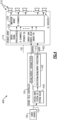
FIG. 5 illustrates an example of an audio system 500 including at least onespeaker array 110 in communication with asound field controller 120 configured to produce an acoustic sound field having two beams. Conventional array systems supporting two beams divide the number of drivers into two sets and produce one beam from each set. In some conventional systems that include more than one speaker array the drivers among the various speaker arrays are also divided into two sets and each set is used to provide one beam. This conventional approach uses half as many drivers to produce each beam as compared to a case where only one beam is being produced, thus producing beams having less desirable characteristics, such as less accuracy in the desired or intended beam pattern (e.g., direction, spreading, sidelobes, etc.). An alternate conventional approach includes calculation of a more precise response for each driver in the array to allow extensive control of the sound field produced. Such an approach is computationally challenging, requires significant calculational resources, and may require speaker arrays with significantly increased processing capability to implement the precise response required of each driver. The audio system 500, however, includes a solution that produces two beams, each beam having the precision of using all the drivers in the array, while being cheaper, less complex, and more easily adjustable than conventional, computationally extensive, approaches. - In the audio system 500, the
sound field controller 120 processes theaudio signal 152 through twobeam processors speaker arrays 110 include twosignal processor channels driver 210, one for each beam, that further process the processed audio signals 452a, 452b to provide beam-specific driver signals specific driver signal combiners 232 to provide combined processedsignals 252 to theamplifiers 220, which then provide individual amplifiedsignals 222 to each of thedrivers 210. It should be understood that addition of the beam-specific driver signals combiners 232 may be performed within one or more DSP's that implement any of theprocesser channels 230. - Each beam has its own set of beam-specific parameters, e.g., gain, delay, FIR, equalization, etc. per
driver 210, as appropriate for the situation. Each of thebeam processors 230 associated with thespeaker array 110 processes one of the beams by applying the respective beam-specific parameters, perdriver 210. Accordingly, thesound field controller 120 provides two sets ofarray parameters 410 to the speaker array(s) 110, one set of array parameters for the first beam, which are applied to the first set ofprocessor channels 230a, and another set of array parameters for the second beam, which are applied to the second set ofprocessor channels 230b. It should be understood from the above discussion that aspeaker array 110 in accord with this example has two DSP channels perdriver 210, or equivalently stated, eachdriver 210 has two DSP channels, one for each beam to which thedriver 210 will contribute. The pair of signals produced by the two DSP channels are combined together and the combined signal is amplified before providing to thedriver 210. - In such manner, each of the
drivers 210 of the speaker array(s) 110 will produce an acoustic wave that combines with the acoustic waves of all theother drivers 210 to produce an acoustic sound field having two beams. Each beam will have the precision or quality of having been produced by all thedrivers 210 of the array, and not just by a subset of thedrivers 210. - A benefit of the example audio system 500 is that each beam is individually adjustable within the sound field controller 120 (by
processors processors user 142 wants to adjust equalization or gain of one of the beams without affecting the other beam, such may be applied in one of theprocessors 430 of thesound field controller 120. In conventional systems individual adjustment to a single beam either requires that each beam be produced only by a subset of the drivers, or requires complex recalculation of array parameters for each driver. For example, in conventional systems that produce multiple beams using all available drivers, the information necessary to produce each beam is intermingled within the driver-specific array parameters, and not separable, thus requiring recalculation of the parameters to create all the beams when it is desired to make a change to only one of the beams. Such requires the speaker array(s) to have increased resources to perform the extensive calculations, or requires the parameters to be calculated elsewhere and transferred, requiring a significant amount of data transmission, to apply the newly calculated parameters. - It should be understood that the example audio system 500 processes signals for and produces two beams, but may be extended to any number of beams desired to accommodate varying operational demands or applications. For example, the
sound field controller 120 may includeadditional processing 430 channels, e.g.,beam 1processing 430a,beam 2processing 430b, beam 3 processing, and so on up to beam M processing, to provide M number of processed audio signals 452, one for each beam. Thespeaker array 110 may includeMxN DSP 230 channels to process the M beam signals for each of theN drivers 210, andM combiners 232 to add together the M beam-specific driver signals 254 to provide N combinedsignals 252, one for eachdriver 210. - Among the various examples discussed above reference is made at times to one or more signal processing channels. It should be understood that various signal processing channels may be digital or analog in nature and that specific examples of digital signal processing channels may have analog counterparts substituted therefore, and that analog signal processing may have digital counterparts substituted therefore. It should be understood that conversion of signals from digital to analog, and vice-versa, are well known in the art and such conversion may include one or more digital-to-analog converters (DAC) and/or analog-to-digital converters (ADC), respectively. In the examples discussed above such conversion may be included though the conversion may not be discussed or shown. Those of skill in the art will understand how to make such conversion as necessary to implement the examples discussed. In particular, it should be understood that processing in a
sound field controller 120, and in one ormore DSP 230 channels of aspeaker array 110, may occur in the digital domain while a signal (processed, combined, amplified, etc.) provided to an amplifier or to a driver may be analog. Accordingly, a DAC may be provided between, e.g., aDSP 230 and anamplifier 220, to convert a processed digital signal into an analog signal to be amplified. - Having described above several aspects of at least one example, it is to be appreciated various alterations, modifications, and improvements will readily occur to those skilled in the art. Such alterations, modifications, and improvements are intended to be part of this disclosure and are intended to be within the scope of the invention. Accordingly, the foregoing description and drawings are by way of example only, and the scope of the invention is defined by the appended claims
Claims (7)
- An acoustic array system (100) comprising:a sound field controller (120) including at least one signal processor configured to process an audio signal (250) to provide a first processed signal associated with a first acoustic radiation pattern and to provide a second processed signal associated with a second acoustic radiation pattern; andtwo or more acoustic transducer arrays (110) daisy-chained, each including at least one signal processor (230) and a plurality of acoustic transducers (210), the acoustic transducer array (110) configured to receive the first and second processed signals from the sound field controller (120), produce a first driver signal for each of the acoustic transducers (210) based upon the first processed signal, produce a second driver signal for each of the acoustic transducers based upon the second processed signal, and combine the first and second driver signals for each of the plurality of acoustic transducers to produce a plurality of combined driver signals, one for each of the acoustic transducers (210), and provide at least one combined driver signal (252) to each of the acoustic transducers (210),each of the acoustic transducer arrays (110) is configured to communicate with each other via daisy-chain connections (352, 354); andthe first acoustic transducer array (110) is configured to communicate with the sound field controller (120).
- The system of claim 1 wherein the acoustic transducer array (110) is configured to produce the first driver signal for each of the acoustic transducers (210) based at least in part upon a parameter associated with the first acoustic radiation pattern.
- The system of claim 2 wherein the parameter is at least one of a gain, an amplitude, a time delay, a phase delay, a finite impulse response, and an equalization.
- The system of claim 2 wherein the sound field controller is configured to store the parameter and to provide the parameter to the acoustic transducer array.
- The system of claim 1 wherein the sound field controller is configured to select an amplitude and delay of each of the plurality of acoustic transducers (210), to cause the acoustic transducer array (110) to generate the first acoustic radiation pattern.
- The system of claim 5 wherein the sound field controller (120) is configured to provide the amplitude and delay of each of the plurality of acoustic transducers (210) to the acoustic transducer array (110), and the acoustic transducer array (110) is configured to apply the amplitude and delay to each of the plurality of acoustic transducers (210).
- The system of claim 1 wherein the acoustic transducer system comprises a second acoustic transducer array (110) configured to receive the first and second processed signals from the first acoustic transducer array (110).
Applications Claiming Priority (2)
| Application Number | Priority Date | Filing Date | Title |
|---|---|---|---|
| US15/581,452 US10349199B2 (en) | 2017-04-28 | 2017-04-28 | Acoustic array systems |
| PCT/US2018/029721 WO2018200912A1 (en) | 2017-04-28 | 2018-04-27 | Acoustic array systems |
Publications (2)
| Publication Number | Publication Date |
|---|---|
| EP3616412A1 EP3616412A1 (en) | 2020-03-04 |
| EP3616412B1 true EP3616412B1 (en) | 2025-01-22 |
Family
ID=62167956
Family Applications (1)
| Application Number | Title | Priority Date | Filing Date |
|---|---|---|---|
| EP18725085.7A Active EP3616412B1 (en) | 2017-04-28 | 2018-04-27 | Acoustic speaker array systems |
Country Status (4)
| Country | Link |
|---|---|
| US (1) | US10349199B2 (en) |
| EP (1) | EP3616412B1 (en) |
| CN (1) | CN110720225B (en) |
| WO (1) | WO2018200912A1 (en) |
Families Citing this family (6)
| Publication number | Priority date | Publication date | Assignee | Title |
|---|---|---|---|---|
| US10531196B2 (en) * | 2017-06-02 | 2020-01-07 | Apple Inc. | Spatially ducking audio produced through a beamforming loudspeaker array |
| US11170752B1 (en) * | 2020-04-29 | 2021-11-09 | Gulfstream Aerospace Corporation | Phased array speaker and microphone system for cockpit communication |
| WO2022047458A1 (en) * | 2020-08-24 | 2022-03-03 | Sonos, Inc. | Multichannel playback devices and associated systems and methods |
| CN113011006B (en) * | 2021-02-25 | 2021-10-22 | 中国科学院声学研究所 | Target depth estimation method based on cross-correlation function pulse waveform matching |
| US12507028B2 (en) | 2023-03-30 | 2025-12-23 | Adeia Guides Inc. | Systems and methods for providing spatial audio from devices |
| US20240334148A1 (en) * | 2023-03-30 | 2024-10-03 | Adeia Guides Inc. | Systems and methods for spatially enhanced audio communications |
Citations (2)
| Publication number | Priority date | Publication date | Assignee | Title |
|---|---|---|---|---|
| US20120163636A1 (en) * | 2010-12-22 | 2012-06-28 | Samsung Electronics Co., Ltd. | Method and apparatus for creating personal sound zone |
| WO2017033574A1 (en) * | 2015-08-21 | 2017-03-02 | ソニー株式会社 | Projection system and apparatus unit |
Family Cites Families (24)
| Publication number | Priority date | Publication date | Assignee | Title |
|---|---|---|---|---|
| NL9401860A (en) | 1994-11-08 | 1996-06-03 | Duran Bv | Loudspeaker system with controlled directivity. |
| WO2001023104A2 (en) * | 1999-09-29 | 2001-04-05 | 1...Limited | Method and apparatus to direct sound using an array of output transducers |
| US7260235B1 (en) | 2000-10-16 | 2007-08-21 | Bose Corporation | Line electroacoustical transducing |
| GB0124352D0 (en) * | 2001-10-11 | 2001-11-28 | 1 Ltd | Signal processing device for acoustic transducer array |
| JP4007254B2 (en) * | 2003-06-02 | 2007-11-14 | ヤマハ株式会社 | Array speaker system |
| JP2005197896A (en) * | 2004-01-05 | 2005-07-21 | Yamaha Corp | Audio signal supply apparatus for speaker array |
| JP4127248B2 (en) | 2004-06-23 | 2008-07-30 | ヤマハ株式会社 | Speaker array device and audio beam setting method for speaker array device |
| JP4501559B2 (en) * | 2004-07-07 | 2010-07-14 | ヤマハ株式会社 | Directivity control method of speaker device and audio reproducing device |
| US20060018490A1 (en) | 2004-07-20 | 2006-01-26 | Stiles Enrique M | Bessel array |
| JP2006262416A (en) | 2005-03-18 | 2006-09-28 | Yamaha Corp | Acoustic system, method of controlling acoustic system, and acoustic apparatus |
| WO2007007446A1 (en) | 2005-07-14 | 2007-01-18 | Yamaha Corporation | Array speaker system and array microphone system |
| US7936891B2 (en) | 2005-10-06 | 2011-05-03 | Henricksen Clifford A | Line array electroacoustical transducing |
| US9031267B2 (en) | 2007-08-29 | 2015-05-12 | Microsoft Technology Licensing, Llc | Loudspeaker array providing direct and indirect radiation from same set of drivers |
| CN101656908A (en) | 2008-08-19 | 2010-02-24 | 深圳华为通信技术有限公司 | Method for controlling sound focusing, communication device and communication system |
| WO2011135646A1 (en) | 2010-04-26 | 2011-11-03 | ティーオーエー株式会社 | Speaker device and filter coefficient generation device therefor |
| US9161129B2 (en) * | 2010-06-22 | 2015-10-13 | Nokia Corporation | Arranging an audio signal based on the number of loudspeakers |
| WO2012032335A1 (en) | 2010-09-06 | 2012-03-15 | Cambridge Mechatronics Limited | Array loudspeaker system |
| CN102404672B (en) | 2011-10-27 | 2013-12-18 | 苏州上声电子有限公司 | Method and device for controlling channel equalization and beam of digital loudspeaker array system |
| CN103385009B (en) * | 2011-12-27 | 2017-03-15 | 松下知识产权经营株式会社 | Sound field controlling device and sound field control method |
| JP5958717B2 (en) * | 2013-07-19 | 2016-08-02 | パナソニックIpマネジメント株式会社 | Directivity control system, directivity control method, sound collection system, and sound collection control method |
| JP6515200B2 (en) * | 2015-04-02 | 2019-05-15 | ドルビー ラボラトリーズ ライセンシング コーポレイション | Distributed Amplification for Adaptive Audio Rendering System |
| JP6657375B2 (en) | 2015-08-13 | 2020-03-04 | ホアウェイ・テクノロジーズ・カンパニー・リミテッド | Audio signal processing device and acoustic radiation device |
| WO2017039633A1 (en) * | 2015-08-31 | 2017-03-09 | Nunntawi Dynamics Llc | Spatial compressor for beamforming speakers |
| US10129644B2 (en) | 2017-01-30 | 2018-11-13 | Loud Audio, Llc | Systems and methods for adaptive zone control of a large scale audio system |
-
2017
- 2017-04-28 US US15/581,452 patent/US10349199B2/en active Active
-
2018
- 2018-04-27 CN CN201880036460.6A patent/CN110720225B/en active Active
- 2018-04-27 WO PCT/US2018/029721 patent/WO2018200912A1/en not_active Ceased
- 2018-04-27 EP EP18725085.7A patent/EP3616412B1/en active Active
Patent Citations (3)
| Publication number | Priority date | Publication date | Assignee | Title |
|---|---|---|---|---|
| US20120163636A1 (en) * | 2010-12-22 | 2012-06-28 | Samsung Electronics Co., Ltd. | Method and apparatus for creating personal sound zone |
| WO2017033574A1 (en) * | 2015-08-21 | 2017-03-02 | ソニー株式会社 | Projection system and apparatus unit |
| EP3340649A1 (en) * | 2015-08-21 | 2018-06-27 | Sony Corporation | Projection system and apparatus unit |
Also Published As
| Publication number | Publication date |
|---|---|
| US20180317035A1 (en) | 2018-11-01 |
| WO2018200912A1 (en) | 2018-11-01 |
| CN110720225B (en) | 2021-09-10 |
| US10349199B2 (en) | 2019-07-09 |
| CN110720225A (en) | 2020-01-21 |
| EP3616412A1 (en) | 2020-03-04 |
Similar Documents
| Publication | Publication Date | Title |
|---|---|---|
| EP3616413B1 (en) | Speaker array systems | |
| US10349199B2 (en) | Acoustic array systems | |
| CN114051738B (en) | Steerable speaker array, system and method thereof | |
| US12262190B2 (en) | Automobile audio soundstage control | |
| CN101267686B (en) | Speaker array apparatus and signal processing method therefor | |
| US20040151325A1 (en) | Method and apparatus to create a sound field | |
| JP7071961B2 (en) | Variable acoustic loudspeaker | |
| US10848863B2 (en) | Acoustic radiation pattern control | |
| GB2373956A (en) | Method and apparatus to create a sound field | |
| JP5685524B2 (en) | Direct the sound field of the actuator | |
| US10536795B2 (en) | Vehicle audio system with reverberant content presentation | |
| JP2006191285A (en) | Array speaker system and audio signal processing apparatus thereof | |
| WO2023220348A1 (en) | Directional sound-producing device | |
| WO2016087875A1 (en) | A mixing console with solo output | |
| US11323812B2 (en) | Signal processing apparatus, signal processing method, and signal processing system | |
| WO2021053874A1 (en) | Signal processing apparatus, signal processing method, and signal processing system | |
| US8687822B1 (en) | Filtering system for equalizing a loudspeaker system |
Legal Events
| Date | Code | Title | Description |
|---|---|---|---|
| STAA | Information on the status of an ep patent application or granted ep patent |
Free format text: STATUS: UNKNOWN |
|
| STAA | Information on the status of an ep patent application or granted ep patent |
Free format text: STATUS: THE INTERNATIONAL PUBLICATION HAS BEEN MADE |
|
| PUAI | Public reference made under article 153(3) epc to a published international application that has entered the european phase |
Free format text: ORIGINAL CODE: 0009012 |
|
| STAA | Information on the status of an ep patent application or granted ep patent |
Free format text: STATUS: REQUEST FOR EXAMINATION WAS MADE |
|
| 17P | Request for examination filed |
Effective date: 20191029 |
|
| AK | Designated contracting states |
Kind code of ref document: A1 Designated state(s): AL AT BE BG CH CY CZ DE DK EE ES FI FR GB GR HR HU IE IS IT LI LT LU LV MC MK MT NL NO PL PT RO RS SE SI SK SM TR |
|
| AX | Request for extension of the european patent |
Extension state: BA ME |
|
| DAV | Request for validation of the european patent (deleted) | ||
| DAX | Request for extension of the european patent (deleted) | ||
| STAA | Information on the status of an ep patent application or granted ep patent |
Free format text: STATUS: EXAMINATION IS IN PROGRESS |
|
| 17Q | First examination report despatched |
Effective date: 20210907 |
|
| GRAP | Despatch of communication of intention to grant a patent |
Free format text: ORIGINAL CODE: EPIDOSNIGR1 |
|
| STAA | Information on the status of an ep patent application or granted ep patent |
Free format text: STATUS: GRANT OF PATENT IS INTENDED |
|
| INTG | Intention to grant announced |
Effective date: 20241023 |
|
| GRAS | Grant fee paid |
Free format text: ORIGINAL CODE: EPIDOSNIGR3 |
|
| GRAA | (expected) grant |
Free format text: ORIGINAL CODE: 0009210 |
|
| STAA | Information on the status of an ep patent application or granted ep patent |
Free format text: STATUS: THE PATENT HAS BEEN GRANTED |
|
| AK | Designated contracting states |
Kind code of ref document: B1 Designated state(s): AL AT BE BG CH CY CZ DE DK EE ES FI FR GB GR HR HU IE IS IT LI LT LU LV MC MK MT NL NO PL PT RO RS SE SI SK SM TR |
|
| REG | Reference to a national code |
Ref country code: GB Ref legal event code: FG4D |
|
| REG | Reference to a national code |
Ref country code: CH Ref legal event code: EP |
|
| REG | Reference to a national code |
Ref country code: IE Ref legal event code: FG4D |
|
| REG | Reference to a national code |
Ref country code: DE Ref legal event code: R096 Ref document number: 602018078656 Country of ref document: DE |
|
| REG | Reference to a national code |
Ref country code: NL Ref legal event code: MP Effective date: 20250122 |
|
| PG25 | Lapsed in a contracting state [announced via postgrant information from national office to epo] |
Ref country code: NL Free format text: LAPSE BECAUSE OF FAILURE TO SUBMIT A TRANSLATION OF THE DESCRIPTION OR TO PAY THE FEE WITHIN THE PRESCRIBED TIME-LIMIT Effective date: 20250122 |
|
| PG25 | Lapsed in a contracting state [announced via postgrant information from national office to epo] |
Ref country code: RS Free format text: LAPSE BECAUSE OF FAILURE TO SUBMIT A TRANSLATION OF THE DESCRIPTION OR TO PAY THE FEE WITHIN THE PRESCRIBED TIME-LIMIT Effective date: 20250422 |
|
| PG25 | Lapsed in a contracting state [announced via postgrant information from national office to epo] |
Ref country code: FI Free format text: LAPSE BECAUSE OF FAILURE TO SUBMIT A TRANSLATION OF THE DESCRIPTION OR TO PAY THE FEE WITHIN THE PRESCRIBED TIME-LIMIT Effective date: 20250122 |
|
| PG25 | Lapsed in a contracting state [announced via postgrant information from national office to epo] |
Ref country code: PL Free format text: LAPSE BECAUSE OF FAILURE TO SUBMIT A TRANSLATION OF THE DESCRIPTION OR TO PAY THE FEE WITHIN THE PRESCRIBED TIME-LIMIT Effective date: 20250122 |
|
| PGFP | Annual fee paid to national office [announced via postgrant information from national office to epo] |
Ref country code: DE Payment date: 20250319 Year of fee payment: 8 |
|
| PG25 | Lapsed in a contracting state [announced via postgrant information from national office to epo] |
Ref country code: ES Free format text: LAPSE BECAUSE OF FAILURE TO SUBMIT A TRANSLATION OF THE DESCRIPTION OR TO PAY THE FEE WITHIN THE PRESCRIBED TIME-LIMIT Effective date: 20250122 |
|
| REG | Reference to a national code |
Ref country code: LT Ref legal event code: MG9D |
|
| PG25 | Lapsed in a contracting state [announced via postgrant information from national office to epo] |
Ref country code: NO Free format text: LAPSE BECAUSE OF FAILURE TO SUBMIT A TRANSLATION OF THE DESCRIPTION OR TO PAY THE FEE WITHIN THE PRESCRIBED TIME-LIMIT Effective date: 20250422 Ref country code: IS Free format text: LAPSE BECAUSE OF FAILURE TO SUBMIT A TRANSLATION OF THE DESCRIPTION OR TO PAY THE FEE WITHIN THE PRESCRIBED TIME-LIMIT Effective date: 20250522 |
|
| REG | Reference to a national code |
Ref country code: AT Ref legal event code: MK05 Ref document number: 1762364 Country of ref document: AT Kind code of ref document: T Effective date: 20250122 |
|
| PG25 | Lapsed in a contracting state [announced via postgrant information from national office to epo] |
Ref country code: HR Free format text: LAPSE BECAUSE OF FAILURE TO SUBMIT A TRANSLATION OF THE DESCRIPTION OR TO PAY THE FEE WITHIN THE PRESCRIBED TIME-LIMIT Effective date: 20250122 |
|
| PG25 | Lapsed in a contracting state [announced via postgrant information from national office to epo] |
Ref country code: LV Free format text: LAPSE BECAUSE OF FAILURE TO SUBMIT A TRANSLATION OF THE DESCRIPTION OR TO PAY THE FEE WITHIN THE PRESCRIBED TIME-LIMIT Effective date: 20250122 Ref country code: PT Free format text: LAPSE BECAUSE OF FAILURE TO SUBMIT A TRANSLATION OF THE DESCRIPTION OR TO PAY THE FEE WITHIN THE PRESCRIBED TIME-LIMIT Effective date: 20250522 |
|
| PG25 | Lapsed in a contracting state [announced via postgrant information from national office to epo] |
Ref country code: BG Free format text: LAPSE BECAUSE OF FAILURE TO SUBMIT A TRANSLATION OF THE DESCRIPTION OR TO PAY THE FEE WITHIN THE PRESCRIBED TIME-LIMIT Effective date: 20250122 Ref country code: GR Free format text: LAPSE BECAUSE OF FAILURE TO SUBMIT A TRANSLATION OF THE DESCRIPTION OR TO PAY THE FEE WITHIN THE PRESCRIBED TIME-LIMIT Effective date: 20250423 |
|
| PG25 | Lapsed in a contracting state [announced via postgrant information from national office to epo] |
Ref country code: AT Free format text: LAPSE BECAUSE OF FAILURE TO SUBMIT A TRANSLATION OF THE DESCRIPTION OR TO PAY THE FEE WITHIN THE PRESCRIBED TIME-LIMIT Effective date: 20250122 |
|
| PG25 | Lapsed in a contracting state [announced via postgrant information from national office to epo] |
Ref country code: SE Free format text: LAPSE BECAUSE OF FAILURE TO SUBMIT A TRANSLATION OF THE DESCRIPTION OR TO PAY THE FEE WITHIN THE PRESCRIBED TIME-LIMIT Effective date: 20250122 |
|
| PG25 | Lapsed in a contracting state [announced via postgrant information from national office to epo] |
Ref country code: SM Free format text: LAPSE BECAUSE OF FAILURE TO SUBMIT A TRANSLATION OF THE DESCRIPTION OR TO PAY THE FEE WITHIN THE PRESCRIBED TIME-LIMIT Effective date: 20250122 |
|
| PG25 | Lapsed in a contracting state [announced via postgrant information from national office to epo] |
Ref country code: DK Free format text: LAPSE BECAUSE OF FAILURE TO SUBMIT A TRANSLATION OF THE DESCRIPTION OR TO PAY THE FEE WITHIN THE PRESCRIBED TIME-LIMIT Effective date: 20250122 |
|
| PG25 | Lapsed in a contracting state [announced via postgrant information from national office to epo] |
Ref country code: IT Free format text: LAPSE BECAUSE OF FAILURE TO SUBMIT A TRANSLATION OF THE DESCRIPTION OR TO PAY THE FEE WITHIN THE PRESCRIBED TIME-LIMIT Effective date: 20250122 |
|
| PG25 | Lapsed in a contracting state [announced via postgrant information from national office to epo] |
Ref country code: CZ Free format text: LAPSE BECAUSE OF FAILURE TO SUBMIT A TRANSLATION OF THE DESCRIPTION OR TO PAY THE FEE WITHIN THE PRESCRIBED TIME-LIMIT Effective date: 20250122 Ref country code: EE Free format text: LAPSE BECAUSE OF FAILURE TO SUBMIT A TRANSLATION OF THE DESCRIPTION OR TO PAY THE FEE WITHIN THE PRESCRIBED TIME-LIMIT Effective date: 20250122 |
|
| REG | Reference to a national code |
Ref country code: DE Ref legal event code: R097 Ref document number: 602018078656 Country of ref document: DE |
|
| PG25 | Lapsed in a contracting state [announced via postgrant information from national office to epo] |
Ref country code: RO Free format text: LAPSE BECAUSE OF FAILURE TO SUBMIT A TRANSLATION OF THE DESCRIPTION OR TO PAY THE FEE WITHIN THE PRESCRIBED TIME-LIMIT Effective date: 20250122 |
|
| PG25 | Lapsed in a contracting state [announced via postgrant information from national office to epo] |
Ref country code: SK Free format text: LAPSE BECAUSE OF FAILURE TO SUBMIT A TRANSLATION OF THE DESCRIPTION OR TO PAY THE FEE WITHIN THE PRESCRIBED TIME-LIMIT Effective date: 20250122 |
|
| REG | Reference to a national code |
Ref country code: CH Ref legal event code: H13 Free format text: ST27 STATUS EVENT CODE: U-0-0-H10-H13 (AS PROVIDED BY THE NATIONAL OFFICE) Effective date: 20251125 |
|
| PLBE | No opposition filed within time limit |
Free format text: ORIGINAL CODE: 0009261 |
|
| STAA | Information on the status of an ep patent application or granted ep patent |
Free format text: STATUS: NO OPPOSITION FILED WITHIN TIME LIMIT |
|
| PG25 | Lapsed in a contracting state [announced via postgrant information from national office to epo] |
Ref country code: LU Free format text: LAPSE BECAUSE OF NON-PAYMENT OF DUE FEES Effective date: 20250427 |
|
| PG25 | Lapsed in a contracting state [announced via postgrant information from national office to epo] |
Ref country code: MC Free format text: LAPSE BECAUSE OF FAILURE TO SUBMIT A TRANSLATION OF THE DESCRIPTION OR TO PAY THE FEE WITHIN THE PRESCRIBED TIME-LIMIT Effective date: 20250122 |
|
| REG | Reference to a national code |
Ref country code: BE Ref legal event code: MM Effective date: 20250430 |
|
| 26N | No opposition filed |
Effective date: 20251023 |
|
| PG25 | Lapsed in a contracting state [announced via postgrant information from national office to epo] |
Ref country code: BE Free format text: LAPSE BECAUSE OF NON-PAYMENT OF DUE FEES Effective date: 20250430 |
|
| PG25 | Lapsed in a contracting state [announced via postgrant information from national office to epo] |
Ref country code: CH Free format text: LAPSE BECAUSE OF NON-PAYMENT OF DUE FEES Effective date: 20250430 |
|
| PGFP | Annual fee paid to national office [announced via postgrant information from national office to epo] |
Ref country code: GB Payment date: 20260319 Year of fee payment: 9 |
|
| PG25 | Lapsed in a contracting state [announced via postgrant information from national office to epo] |
Ref country code: IE Free format text: LAPSE BECAUSE OF NON-PAYMENT OF DUE FEES Effective date: 20250427 |
|
| PGFP | Annual fee paid to national office [announced via postgrant information from national office to epo] |
Ref country code: FR Payment date: 20260320 Year of fee payment: 9 |