EP3616002B1 - Mehrfrequenz-infrarotbildgebung auf basis von frequenzumwandlung - Google Patents
Mehrfrequenz-infrarotbildgebung auf basis von frequenzumwandlung Download PDFInfo
- Publication number
- EP3616002B1 EP3616002B1 EP18790570.8A EP18790570A EP3616002B1 EP 3616002 B1 EP3616002 B1 EP 3616002B1 EP 18790570 A EP18790570 A EP 18790570A EP 3616002 B1 EP3616002 B1 EP 3616002B1
- Authority
- EP
- European Patent Office
- Prior art keywords
- crystal
- pump
- light
- input
- infrared
- Prior art date
- Legal status (The legal status is an assumption and is not a legal conclusion. Google has not performed a legal analysis and makes no representation as to the accuracy of the status listed.)
- Active
Links
Images

Classifications
-
- G—PHYSICS
- G02—OPTICS
- G02F—OPTICAL DEVICES OR ARRANGEMENTS FOR THE CONTROL OF LIGHT BY MODIFICATION OF THE OPTICAL PROPERTIES OF THE MEDIA OF THE ELEMENTS INVOLVED THEREIN; NON-LINEAR OPTICS; FREQUENCY-CHANGING OF LIGHT; OPTICAL LOGIC ELEMENTS; OPTICAL ANALOGUE/DIGITAL CONVERTERS
- G02F1/00—Devices or arrangements for the control of the intensity, colour, phase, polarisation or direction of light arriving from an independent light source, e.g. switching, gating or modulating; Non-linear optics
- G02F1/35—Non-linear optics
- G02F1/353—Frequency conversion, i.e. wherein a light beam is generated with frequency components different from those of the incident light beams
- G02F1/3534—Three-wave interaction, e.g. sum-difference frequency generation
-
- G—PHYSICS
- G02—OPTICS
- G02F—OPTICAL DEVICES OR ARRANGEMENTS FOR THE CONTROL OF LIGHT BY MODIFICATION OF THE OPTICAL PROPERTIES OF THE MEDIA OF THE ELEMENTS INVOLVED THEREIN; NON-LINEAR OPTICS; FREQUENCY-CHANGING OF LIGHT; OPTICAL LOGIC ELEMENTS; OPTICAL ANALOGUE/DIGITAL CONVERTERS
- G02F1/00—Devices or arrangements for the control of the intensity, colour, phase, polarisation or direction of light arriving from an independent light source, e.g. switching, gating or modulating; Non-linear optics
- G02F1/35—Non-linear optics
- G02F1/3526—Non-linear optics using two-photon emission or absorption processes
-
- H—ELECTRICITY
- H04—ELECTRIC COMMUNICATION TECHNIQUE
- H04N—PICTORIAL COMMUNICATION, e.g. TELEVISION
- H04N23/00—Cameras or camera modules comprising electronic image sensors; Control thereof
- H04N23/20—Cameras or camera modules comprising electronic image sensors; Control thereof for generating image signals from infrared radiation only
- H04N23/21—Cameras or camera modules comprising electronic image sensors; Control thereof for generating image signals from infrared radiation only from near infrared [NIR] radiation
Definitions
- the present invention in some embodiments thereof, relates to imaging and, more particularly, but not exclusively, to a method and a system for infrared imaging.
- Imaging of infrared radiation may in general be considered as advantageous, since infrared radiation may carry information which is not obtainable by merely obtaining the images from other types of optical radiation, e.g ., the visible radiation.
- U.S. Patent No. 6,687,051 describes an image apparatus for converting infrared light into visible light.
- the apparatus includes an object lens with an optical crystal and an infrared object lens.
- the object lens converts an infrared light spectrum image into a visible light spectrum image.
- U.S. Patent No. 8,331,017 describes a quasi-phase matched non-linear crystal for wavelength conversion.
- the crystal has an aperiodic poled structure, where each period is tuned in a manner that the tuning varies adiabatically along a length of the crystal from a strong negative mismatch at one end of the crystal to a strong positive mismatch at another end of the crystal.
- Mid-infrared light is upconverted in a single pass through a nonlinear crystal that mixes the mid-infrared light with a laser beam, to generate the upconverted light at near-visible wavelengths.
- the phase-match condition of the nonlinear crystal is varied, and images are individually acquired for each phase-match condition, to obtain a set of images, each containing light from only one specific narrow band of wavelengths.
- Image reconstruction is then employed to piece together the set of individually acquired images.
- the bandwidth of the upconversion system varies with the phase-matched wavelength, and reaches a maximum of 200 nm at 4.2 mm, beyond which it decreases.
- Suchowski et al. “Geometrical representation of sum frequency generation and adiabatic frequency conversion", Physical Review A 78, 063821 (2008 ); Suchowski et al., Opt. Exp 17, 12732 (2009 ); Suchowski et al., “Adiabatic frequency conversion of ultrafast pulses", Applied Physics B 105, 697 (2011 ); Suchowski et al., “Adiabatic processes in frequency conversion", Laser and Photonics Reviews 8, 333 (2014 ); Suchowski et al., “Octave-spanning coherent mid-IR pulses via adiabatic difference frequency generation", Opt. Exp.
- Implementation of the method and/or system of embodiments of the invention can involve performing or completing selected tasks manually, automatically, or a combination thereof. Moreover, according to actual instrumentation and equipment of embodiments of the method and/or system of the invention, several selected tasks could be implemented by hardware, by software or by firmware or by a combination thereof using an operating system.
- a data processor such as a computing platform for executing a plurality of instructions.
- the data processor includes a volatile memory for storing instructions and/or data and/or a non-volatile storage, for example, a magnetic hard-disk and/or removable media, for storing instructions and/or data.
- a network connection is provided as well.
- a display and/or a user input device such as a keyboard or mouse are optionally provided as well.
- the present invention in some embodiments thereof, relates to imaging and, more particularly, but not exclusively, to a method and a system for infrared imaging.
- mid-infrared (mid-IR) wavelength regime spanning the wavelength range of 2-15 ⁇ m (750-5,000 cm -1 ), is of particular importance to materials science, chemistry, biology and condensed matter physics, as it covers the fundamental vibrational absorption bands of many gaseous molecules and bio-molecules, thus of tremendous scientific and technological interest.
- the characteristic vibrational transitions have line strengths that are several order of magnitude stronger that the near-infrared region, those provide a unique information on a sample's molecular composition, thus the mid-IR is also called the fingerprint region.
- mid-IR spectral region contains two atmospheric transmission windows (3-5 ⁇ m and 8-13 ⁇ m), in which the Earth's atmosphere is relatively transparent, it makes mid-IR laser sources useful for many applications including, without limitation, atmospheric, defense and industrial applications.
- imaging in the IR can be useful for thermal analysis, security and materials inspection.
- infrared imaging systems include infrared cameras which are based on the photo-electric effect.
- Known infrared cameras include mid-wave IR (MWIR) cameras, long-wave IR (LWIR) cameras and short-wave IR (SWIR) cameras.
- MWIR mid-wave IR
- LWIR long-wave IR
- SWIR short-wave IR
- the choice of materials that compose the detectors makes the various systems operate under different circumstances.
- the mid-infrared detectors are based on indium antimonide (InSb), and/or Mercury Cadmium Telluride (MCT) making them expensive, low resolution, suffering from poor sensitivity and slow response.
- InSb indium antimonide
- MCT Mercury Cadmium Telluride
- a single detector scanning systems or line scanning systems are conventionally used. This requires very accurate mechanical alignment as well as synchronization algorithms.
- Two-dimensional array detectors are also being used, yet those still have very small number of pixels (hundreds in each axis) and thus have very low spatial resolution compared to the current state of the art in Silicon-based cameras (thousands of pixels in each axis).
- the detector of a MWIR camera absorbs all the photons that are above the bandgap and therefore the main problem of thermal imaging is that during the detection process, the spectral components are integrated and cannot be later retrieved.
- spectral mid-IR imaging techniques that are carried out by using a discrete set of bandpass filters, each allowing the transmission of a narrow window of infrared radiation.
- this technique is slow, since it requires the sequential acquisition of images for each filter and requires a significant signal to noise ratio at each spectral window, making it a very low sensitivity technique.
- FIGs. 1A and 1B are schematic illustrations of an imaging system 10, according to some embodiments of the present invention.
- System 10 comprises a light source 12 generating a pump beam 14, and an optical coupling system 16.
- Optical coupling system 16 receives a coherent or incoherent input beam 18 of infrared light from a scene 20, optionally and preferably via a lens system 32, and combines the input beam 18 with the pump beam 14.
- the intensity of pump beam 14 is higher than the intensity of input beam 18.
- Optical coupling system 16 can include any optical coupler known in the art that can in-couple two or more light beams.
- coupling system 16 can be a lens or lens array, a diffractive element, a fiber optic coupler, a dichroic mirror and the like.
- the pump beam 14 is optionally and preferably characterized by a wavelength range having a central wavelength that is shorter than the central wavelength that is characteristic to the input beam 18.
- the longest wavelength of the pump beam 14 is shorter than the shortest wavelength of the input beam 18.
- the input beam 18 can be a mid-infrared beam ( e.g ., having a plurality of wavelength within the range of 3 ⁇ m to 8 ⁇ m, inclusive), and the pump beam 14 can be a near-infrared beam ( e.g ., having at least one wavelength within the range of 0.7 ⁇ m to 1.5 ⁇ m, inclusive).
- Other wavelengths for beams 14 and 18 are also contemplated.
- light source 12 generates a pulsed pump beam at a repetition rate.
- System 10 can optionally and preferably comprise a cavity 30 characterized by a resonance frequency within a bandwidth of pump beam 14, and having a length selected based on the repetition rate of the pulsed pump beam to synchronize between pulses in the pump beam 14.
- the characteristic pulse duration of the generated pulsed pump beam is less than 10 ns or less than 9 ns or less than 8 ns or less than 7 ns or less than 6 ns or less than 5 ns or less than 4 ns or less than 2 ns or less than 1 ns or less than 0.1 ns.
- the advantage of having a cavity is that it can allow very short pulses for the pump beam and reduce the exposure time that is required for imaging.
- the cavity allows effectively reaching high pump intensity density, and therefore can also be used for frequency conversion with continuous wave pump beam (e.g., 100 W or more).
- System 10 optionally and preferably comprises a crystal 22 that receives beams 14 and 18 from coupling system 16 and adiabatically mixes these beams to provide an output beam 24 having a frequency which is a sum of frequencies of input beam 18 and pump beam 14.
- output beam 24 is a visible light beam (e.g. , having a plurality of wavelength within the range of 400 nm to 800 nm, inclusive).
- output beam 24 can be a near-infrared light beam (e.g ., having a plurality of wavelength within the range of 0.7 ⁇ m to 1.5 ⁇ m, inclusive).
- system 10 comprises cavity 30, the cavity serves for enhancing the mixing power of beams 14 and 18 in crystal 22.
- crystal 22 is configured for simultaneously mixing pump beam 14 with each of a plurality of wavelengths of input beam 18.
- the wavelengths of input beam 18 that are mixed by crystal 22 with pump beam 14 optionally and preferably spans over a wide wavelength band, e.g., over one, two, three or more octaves.
- the wavelengths of input beam 18 that are mixed by crystal 22 with pump beam 14 span over at least 10% or at least 15% or at least 20% or at least 30% or at least 40% or at least 50% or at least 60% or at least 70% or at least 80% or at least 90% of a range of wavelengths defined from about 1.5 ⁇ m to about 20 ⁇ m.
- the lateral area of crystal 22 is optionally and preferably sufficiently large to allow crystal 22 to receives light rays from all or at least most of the objects or portions of objects in scene 20.
- a lateral area of the crystal is selected according to a predetermined Point Spread Function (PSF).
- PSF Point Spread Function
- the PSF relates to the intensity distribution I pump ( x,y ) of the pump beam 14 in the transverse plane x-y, via the Fourier transform or fast Fourier transform:
- PSF FFT I pump x y
- the lateral area of crystal 22 is at least 5 mm by 5 mm, or at least 10 mm by 10 mm or at least 15 mm by 15 mm.
- the lateral area of the crystal can be about 1 mm 2 for every 100 pixels of the imager.
- a 5 megapixel image (2560 ⁇ 1920 pixels) can be achieved using a crystal having lateral dimensions of about 25.6 mm by 19.2 mm
- Crystal 22 achieves efficient broadband frequency conversion using sufficiently strong pump intensity relative to the intensity of the input beam (e.g ., at least two times or at least five times or at least ten times stronger) and by providing the light beams with gradually changing conditions (e.g ., gradual change in the phase mismatch).
- the gradually changing conditions effect a gradual conversion of beam 18 's frequency as it propagates in crystal 22.
- each original frequency component of beam 18 is converted to a converted frequency in the near-infrared or visible or ultraviolet range.
- the conversion is gradual in the sense that as the beam propagates in crystal 22 the intensity of each original frequency component is gradually decreased, and the intensity of each converted frequency component is gradually increased.
- crystal 22 has a periodic or aperiodic structure, and is under a temperature gradient.
- crystal 22 can be in thermal contact with a heating or cooling source (not shown) that applies a thermal gradient along the propagation direction of beams 14 and 18 in crystal 22.
- the beams are exposed to a gradual change of the temperature during their propagation, thereby achieving the aforementioned gradual frequency conversion.
- crystal 22 has a Quasi-phase matching (QPM) structure with adiabatic aperiodic poling.
- QPM Quasi-phase matching
- Quasi-phase matching (QPM) with adiabatic aperiodically poled designs is an efficient crystal structure for achieving adiabatic changes since the structure has periods which can be modified to range over a series of phase mismatches from a negative to a positive mismatch for increasing or decreasing the frequency. Modifying the crystal structure from positive to negative mismatch according to some embodiments of the present invention achieves the desired conversion.
- the present embodiments modify the QPM crystal structure through a gradual change in the tuning characteristics along the crystal.
- the result is efficient frequency conversion over a broad frequency range.
- a particular advantage of crystal 22 is that it can achieve both efficiency and broadband.
- crystal 22 is works in a regime where a strong narrow-band pump (beam 14 in the present embodiments) is introduced into the crystal, along with a weaker broadband beam (beam 18 in the present embodiments) which is to be converted.
- crystal 22 provides continuous adiabatic variation of phase mismatch.
- Crystal 22 has a length dimension z and tuning conditions along the z dimension of the crystal optionally and preferably vary from negative to positive. That is to say, crystal 22 is a quasi-phase matched non-linear crystal, having a longitudinal dimension and having a periodic pole structure comprising a plurality of tuned periods. Tuning of the respective periods varies adiabatically, meaning gradually, along the longitudinal dimension of the crystal.
- adiabatic or “adiabatically” takes its meaning from quantum physics, and refers to the ability of the crystal to set up a quantum mechanical system with the light beams, in which the crystal structure presents to the light beams gradually changing conditions, allowing the system to change its functional form. That is to say, an adiabatic change comprises a change that is sufficiently gradual as to retain an eigenstate of the optical system. This is in contrast with conventional crystals that provide rapidly varying conditions in which there was no time for the functional form of the state (of the quantum mechanical system) to adapt, so that the system remained in its original state. The gradual change in conditions allows the quantum dynamic state to remain stable and respond to the changing conditions. Rapid change by contrast gets ignored.
- phase mismatch optionally and preferably changes adiabatically from a big negative value, or vice versa, as an analogy to the way in which a red detuned field interacts with a two level system, to a big positive value, as an analogy to the blue detuned field.
- the magnitude value of the phase mismatch parameter ⁇ k is preferably large (e.g., at least 10 times larger) in comparison to the value of the coupling coefficient ⁇ .
- ⁇ k optionally and preferably starts with a negative (or positive) value, and ends with a positive (or negative) value.
- the rate of change of ⁇ k is smaller ( e.g ., at least 10 times smaller) than the internal propagation length of the nonlinear process which can be formally written as ( ⁇ k 2 + ⁇ 2 ) 3/2 / ⁇ .
- QPM is a technique in nonlinear optics which allows a transfer of energy from pump frequency to signal and idler frequencies. It offers several advantages over other phase matching techniques, such as the fact that all optical frequencies involved are collinear with each other and all the optical frequencies can have the same polarization, which allows for the access to the largest nonlinear coefficient of the crystal, d 33 .
- the periods and phase mismatch of crystal 22 are preferably selected in accordance with the expected wavelengths of the beams 14 and 18.
- crystal 22 is designed and constructed for adiabatically mixing mid-infrared light with near-infrared light.
- Crystal 22 can be made of any material that is transparent to the input beam 18.
- Representative examples include, without limitation lithium niobate, KTP, cadmium silicon phosphide (CdSiP2), orientation-patterned gallium arsenide (OP-GaAs), and orientation-patterned gallium phosphide (OP-GaP).
- system 10 optionally and preferably comprises a visible, near-infrared or ultraviolet light imager 26 that collects output beam 24, optionally and preferably via an additional lens system 34, and spectrally resolves output beam 24.
- Imager 26 can be of any type known in the art, that is capable of spectrally resolving light.
- imager 26 can be a silicon based imager, such as, but not limited to, an imager that comprises a MOS circuit or a CMOS circuit.
- imager 26 comprises a CMOS imager. It is expected that during the life of a patent maturing from this application many relevant spectral resolving devices will be developed and the scope of the term imagers is intended to include all such new technologies a priori.
- crystal 22 is optimized such that an extent of Kerr effect and/or two-photon absorption due to interaction of light beams 14 and 18 with crystal 22 is less than a predetermined threshold (e.g ., less than 20% or 10% or less than 5% of the image generated by system 10 is deformed due to the Kerr effect). This can be ensured by collecting light beam from a calibrating scene and measuring the frequency conversion efficiency at each of a plurality of locations on a cross-section of the output beam 24 ( e.g ., at each of at least a portion of the pixels of imager 26 ). The parameters of crystal 22 (for example, the periods or temperature gradient) can then be varied or adjusted until the conversion efficiency is substantially uniform ( e.g ., with deviation of less than 10%) across the output beam.
- a predetermined threshold e.g ., less than 20% or 10% or less than 5% of the image generated by system 10 is deformed due to the Kerr effect.
- system 10 comprises more than one crystal for the adiabatic mixing (see FIG. 1B ). These embodiments are useful, for example, for increasing the bandwidth over which system 10 can operate. For example, one crystal can be selected for frequency conversion of a first sub-bandwidth and another crystal can be selected for frequency conversion of a second sub-bandwidth, wherein the combination ( e.g ., concatenation) of all the sub-bandwidths results in the desired bandwidth.
- system 10 optionally and preferably comprises a beam splitter system 36 that splits beam 18 into two or more secondary beams 18a and 18b.
- Each of the secondary beams is then directed to a separate crystal 22a and 22b for frequency conversion as further detailed hereinabove, to provide two or more output beams 24a and 24b.
- the individual output beams 24a and 24b are then combined by a beam combiner system 38 to one output beam 24 that is collected by the imager 26 as further detailed hereinabove.
- Each of the crystals 22a and 22b can be pumped by a separate pump beam, as illustrated in FIG. 1B , or the same pump beam can be used with two or more of the crystals.
- the pump beam 14 from light source 12 can be split, for example, by a beam splitter system (not shown) to two or more secondary pump beams, each directed to a separate crystal.
- pump beam 14 can be fed serially, e.g., by means of suitable optics (not shown), through two or more of the crystals.
- FIG. 1B illustrates an embodiment in which system 10 comprises two crystals 22a and 22b, this need not necessarily be the case, since more than two crystals can be employed.
- One of ordinary skills in the art, provided with the details described herein would know how to construct a system with any number of crystals.
- Beam splitter system 36 can be of any type suitable to receive a light beam and output two or more light beams.
- beam splitter system 36 comprises a tilted semi-transparent reflector, but other types of beam splitter systems, such as, but not limited to, beam splitter systems employing fiber optics, are also contemplated.
- beam combiner system 38 can be of any type suitable to receive two or more light beams and output one light beam.
- beam combiner system 38 comprises a tilted semi-transparent reflector, but other types of beam combiner systems, such as, but not limited to, beam combiner systems employing fiber optics, are also contemplated.
- system 10 comprises an optical filter 40 selected to filter out the frequency or frequencies of pump beam 14 so as not to contaminate the imager with pump frequencies.
- Filter 40 can be positioned anywhere along the optical path of output beam 24, such as, but not limited to, at the output side of crystal 22 or at the input side of imager 26.
- input beam 18 is received of infrared light from a scene, and is combined with a pulsed pump beam, which is typically higher in intensity than the input beam.
- the beams are then transmitted to a crystal that adiabatically mixes the beams to provide an output beam having a frequency which is a sum of frequencies of the input and pump beams.
- the output beam is preferably a visible or near-infrared light beam, as further detailed hereinabove.
- the output beam is collected using a light imager that spectrally resolves the output beam.
- system 10 is used for single shot imaging, without combining image information from several image acquisitions.
- the entire image information of the scene to be imaged is captured once by the input beam without the need to collect the input beam several times.
- This is in distinction from conventional upconversion imaging techniques in which a set of images is acquired, wherein each contains light from a specific narrow band of wavelengths, and image reconstruction techniques are then employed to piece the images together.
- the technique of the present embodiments enjoys several advantages over conventional technique. Unlike conventional infrared imaging, the technique of the present embodiments leads to spectrally resolved imaging of scenes constituted by mid-IR beams where each wavelength in the mid-IR is uniquely mapped to a color in the imager. This means that the technique of the present embodiments allows, for example, remote detection of gaseous composition of dust clouds and more. Additionally, the quantum efficiency (and hence the sensitivity) is expected to be significantly boosted since the quantum efficiency scales linearly with the mixing power.
- System 10 can be used for imaging many types of scenes.
- system 10 is used in microscopy, wherein scene 20 comprises a sample on a microscope slide; in some embodiments of the present invention system 10 is used for outdoor imaging, wherein scene 20 is an outdoor scene; in some embodiments of the present invention system 10 is used for aerial photography wherein scene 20 comprises an aerial view of objects; in some embodiments of the present invention system 10 is used in astronomical imaging, wherein scene 20 is an astronomical scene; and in some embodiments of the present invention system 10 is used in medical imaging wherein scene 20 is a living body or an organ thereof. Also contemplated are embodiments in which system 10 is mounted on a vehicle such as, but not limited to, an automobile, for example, for capturing a rear-view or front-view images of the scene nearby the vehicle.
- a vehicle such as, but not limited to, an automobile, for example, for capturing a rear-view or front-view images of the scene nearby the vehicle.
- compositions, method or structure may include additional ingredients, steps and/or parts, but only if the additional ingredients, steps and/or parts do not materially alter the basic and novel characteristics of the claimed composition, method or structure.
- a compound or “at least one compound” may include a plurality of compounds, including mixtures thereof.
- range format is merely for convenience and brevity and should not be construed as an inflexible limitation on the scope of the invention. Accordingly, the description of a range should be considered to have specifically disclosed all the possible subranges as well as individual numerical values within that range. For example, description of a range such as from 1 to 6 should be considered to have specifically disclosed subranges such as from 1 to 3, from 1 to 4, from 1 to 5, from 2 to 4, from 2 to 6, from 3 to 6 etc., as well as individual numbers within that range, for example, 1, 2, 3, 4, 5, and 6. This applies regardless of the breadth of the range.
- Adiabatic frequency generation allows efficient, robust and scalable transfer of broadband, visible and near-IR lasers to the mid-IR optical regime and vice versa.
- the AFG can resolve the bandwidth-efficiency trade-off in nonlinear frequency conversion, allowing to simultaneously achieve broad bandwidth conversion with good efficiency.
- heretofore AFG has been used to convert laser light sources with very good beam quality, but was not used for transferring spectrally broad images.
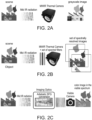
- FIGs. 2A-C illustrate the differences between MWIR imaging ( FIG. 2A ), MWIR hyperspectral imaging ( FIG. 2B ), and the adiabatic sum frequency generation (SFG) of the present embodiments ( FIG. 2C ).
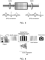
- FIG. 3 is a schematic illustration of the AFG process in adiabatically poled non-linear crystal.
- AFC allows generating broadband pulses in the mid-IR wavelength regime, which outperform the currently available mid-IR ultrashort sources. Unlike other techniques the AFC allows an efficient transfer of broadband, high-energy visible and near-IR lasers to the mid-IR and vice versa.
- the AFC technique applies robust population transfer by rapid adiabatic passage from atomic physics to nonlinear optical frequency conversion, which effectively avoids two main hurdles of optical frequency generation: limited bandwidth and limited conversion efficiency.
- the process is based at least partially on the physical mechanism that the coupled system remains in one of its eigenstates during the entire evolution.
- One of the characteristics of the AFC technique is a conversion efficiency curve that is substantially flat for broad bandwidth, meaning there is a one-to-one mapping of the spectral amplitude and phase of the input signal into the generated new color. From the symmetry of the dynamical equations, both difference frequency generation (DFG) and the sum frequency generation (SFG) can occur.
- SFG conversion a low energy photon (signal) is mixed with a pump photon to yield a photon, idler, of energy higher than both the pump and the signal. This process for example converts VIS-NIR to mid-IR and vice versa with a pump in the NIR.
- the pump photon is the one with the higher energy in the whole process, creating an idler that is of lower energy than the signal.
- flat conversion curve can reach unity for a very broadband spectrum, while for conventional phase matched nonlinear processes (where the phase-mismatch is constant), the conversion curve is very efficiency only over a narrow wavelength range.
- the Inventors of the present invention found that amplitude and phase modulations enacted in the near-IR can be transferred to the mid-IR which can be used for shaping the temporal structure of the mid-IR pulse for coherent control and nonlinear spectroscopy applications.
- the inventors thus successfully combine the adiabatic concept with 2D coherent and incoherent image upconversion, and allow spectrally resolved broadband mid-IR images to be captured, for example, by a conventional silicon high resolution camera.
- the concept is depicted in FIG. 4 .
- the adiabatically poled crystal converts with high efficiency, in a single shot, a broad range of mid IR frequencies contained in the object and the generated VIS-NIR frequencies are imaged onto a Silicon camera to form an image with a one to one relationship between the generated VIS-NIR wavelengths and the original mid-IR wavelengths.
- the mid IR beam is depicted as an oscillating grayscale wave and the VIS-NIR beam is depicted as an oscillating colored wave.
- the mid IR beam is gradually converted into a VIS-NIR beam as it propagates along the crystal.
- the amplitude (hence also the intensity) of mid IR beam is gradually decreased and the amplitude (hence also the intensity) of the VIS-NIR beam is gradually increased.
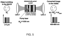
- FIG. 5 illustrates the spectral characteristics of the imaging technique of the present embodiments in greater detail.
- An object is imaged with a magnified 4-f system where the Fourier transform of the object is created using a first lens of focal length f 1 in the crystal.
- the spatial frequencies are encoded as angular position across the crystal facets, rendering the crystal aperture as an effective spatial frequency filter.
- the mid-IR radiation spanning over the range of 2-5 ⁇ m is converted by the crystal to the visible range using a pump laser at, for example, 1030 nm, that is focused on the crystal with a sufficiently long Rayleigh range, allowing efficient conversion along the crystal length.
- the spectrally converted object Fourier transform (optionally and preferably together with some phase to the propagation in the crystal) is transformed back to the image plane with a second lens of focal length f 2 where a visible detector renders the object's image with a magnification of f 2 /f 1 .
- the detector is optionally and preferably equipped with suitable filter to filter out the pump laser and to allow only the wavelengths originating from the image wavelengths conversion to be perceived.
Landscapes
- Physics & Mathematics (AREA)
- Nonlinear Science (AREA)
- General Physics & Mathematics (AREA)
- Optics & Photonics (AREA)
- Engineering & Computer Science (AREA)
- Multimedia (AREA)
- Signal Processing (AREA)
- Health & Medical Sciences (AREA)
- Toxicology (AREA)
- Optical Modulation, Optical Deflection, Nonlinear Optics, Optical Demodulation, Optical Logic Elements (AREA)
Claims (15)
- Ein Bildgebungssystem (10), umfassend:eine Lichtquelle (12), die einen Nah-Infrarot-Pumpstrahl (14) erzeugt;ein optisches Kopplungssystem (16), das konfiguriert ist, um von einer Umgebung (20) einen Eingangsstrahl (18) von Mittel-Infrarot-Licht mit einer Mehrzahl von Wellenlängen zu empfangen und den Eingangsstrahl (18) mit dem Pumpstrahl (14) zu kombinieren, wobei eine Intensität des Pumpstrahls (14) höher ist als eine Intensität des Eingangsstrahls (18);einen Kristall (22), der konfiguriert ist, um den Pumpstrahl (14) gleichzeitig und adiabatisch mit jeder aus der Mehrzahl von Wellenlängen des Eingangsstrahls (18) zu mischen und einen Ausgangsstrahl (24) mit einer Frequenz bereitzustellen, die eine Summe der Frequenzen des Eingangs- (18) und des Pumpstrahls (14) ist; undeinen Bildgeber (26) für sichtbares, Nah-Infrarot- oder ultraviolettes Licht, der konfiguriert ist, um den Ausgangsstrahl (24) zu sammeln und spektral aufzulösen.
- Das System (10) gemäß Anspruch 1, wobei der Ausgangsstrahl (24) ein Ausgangsstrahl aus sichtbarem Licht ist.
- Das System (10) gemäß einem der Ansprüche 1 und 2, wobei der Kristall (22) so optimiert ist, dass ein Ausmaß des Kerr-Effekts und/oder der Zwei-Photonen-Absorption aufgrund der Wechselwirkung der Lichtstrahlen mit dem Kristall (22) kleiner als ein vorbestimmter Schwellenwert ist.
- Das System (10) gemäß einem der Ansprüche 1-3, wobei die Lichtquelle (12) konfiguriert ist, um einen gepulsten Pumpstrahl mit einer Wiederholungsrate zu erzeugen, und das System (10) einen Hohlraum (30) umfasst, der durch eine Resonanzfrequenz innerhalb einer Bandbreite des Pumpstrahls (14) gekennzeichnet ist und eine Länge aufweist, die basierend auf der Wiederholungsrate ausgewählt ist, um zwischen Pulsen in dem Pumpstrahl (14) zu synchronisieren.
- Das System (10) gemäß einem der Ansprüche 1-4, wobei die Lichtquelle (12) zur Erzeugung eines kontinuierlichen Pumpstrahls konfiguriert ist.
- Das System (10) gemäß einem der Ansprüche 1-5, wobei die Mehrzahl von Wellenlängen sich über mindestens 10 % eines Bereichs von Wellenlängen erstreckt, der von etwa 1,5 µm bis etwa 20 µm definiert ist.
- Das System (10) gemäß einem der Ansprüche 1-6, wobei die Lichtquelle (12) zur Erzeugung eines gepulsten Pumpstrahls konfiguriert ist und wobei eine charakteristische Pulsdauer des gepulsten Pumpstrahls weniger als 10 ns beträgt.
- Das System (10) gemäß einem der Ansprüche 1-7, wobei eine laterale Fläche des Kristalls (22) mindestens 5 mm mal 5 mm beträgt.
- Das System (10) gemäß einem der Ansprüche 1-8, wobei der Kristall (22) zum adiabatischen Mischen von Mittel-Infrarot-Licht mit Nah-Infrarot-Licht konfiguriert ist.
- Das System (10) gemäß einem der Ansprüche 1-9, umfassend mindestens zwei Kristalle (22a, 22b), ein Strahlteilersystem (36) und ein Strahlkombinierersystem (38),wobei das Strahlteilersystem (36) konfiguriert ist, um den Eingangsstrahl (18) in mindestens zwei sekundäre Eingangslichtstrahlen (18a, 18b) zu teilen und jeden sekundären Eingangslichtstrahl (18a, 18b) auf einen anderen der mindestens zwei Kristalle (22a, 22b) zu richten,wobei jeder Kristall der mindestens zwei Kristalle (22a, 22b) konfiguriert ist, um einen jeweiligen sekundären Eingangslichtstrahl (18a/18b) adiabatisch mit dem Pumpstrahl (14) zu mischen und einen individuellen jeweiligen Ausgangsstrahl (24a/24b) mit einer Frequenz bereitzustellen, die eine Summe der Frequenzen des sekundären Eingangs- (18a/18b) und des Pumpstrahls (14) ist; undwobei das Strahlkombinierersystem (38) konfiguriert ist, um die individuellen Ausgangsstrahlen (24a, 24b) zu kombinieren, um den Ausgangsstrahl (24) bereitzustellen.
- Das System (10) gemäß einem der Ansprüche 1-10, wobei der Bildgeber (26) Silizium umfasst.
- Ein Verfahren zur Bildgebung, umfassend:Empfangen eines Eingangsstrahls (18) aus Mittel-Infrarot-Licht mit einer Vielzahl von Wellenlängen von einer Umgebung (20);Kombinieren des Eingangsstrahls (18) mit einem Nah-Infrarot-Pumpstrahl (14), wobei eine Intensität des Pumpstrahls (14) höher ist als eine Intensität des Eingangsstrahls (18);Übertragen der Strahlen zu einem Kristall (22), der zum gleichzeitigen und adiabatischen Mischen des Pumpstrahls (14) mit jeder aus der Mehrzahl von Wellenlängen des Eingangsstrahls (18) konfiguriert ist, um einen Ausgangsstrahl (24) für sichtbares oder Nah-Infrarot-Licht mit einer Frequenz bereitzustellen, die eine Summe der Frequenzen des Eingangs- (18) und des Pumpstrahls (14) ist; undSammeln des Ausgangsstrahls (24) unter Verwendung eines Bildgebers (26) für sichtbares, Nah-Infrarot- oder ultraviolettes Licht, der konfiguriert ist, um den Ausgangsstrahl (24) zu sammeln und spektral aufzulösen.
- Das Verfahren gemäß Anspruch 12, wobei eine Intensität des Pumpstrahls (14) so ausgewählt wird, dass ein Ausmaß des Kerr-Effekts aufgrund der Wechselwirkung der Lichtstrahlen mit dem Kristall (22) kleiner als ein vorbestimmter Schwellenwert ist.
- Das Verfahren gemäß einem der Ansprüche 12 und 13, wobei eine Intensität des Pumpstrahls (14) so ausgewählt wird, dass ein Ausmaß der Zwei-Photonen-Absorption aufgrund der Wechselwirkung der Lichtstrahlen mit dem Kristall (22) kleiner als ein vorbestimmter Schwellenwert ist.
- Das Verfahren gemäß einem der Ansprüche 12 bis 14, wobei die Umgebung (20) ausgewählt ist aus der Gruppe bestehend aus: einer Außenumgebung, einer Luftbildumgebung, einer astronomischen Umgebung, einem lebenden Körper oder einem Organ davon und einer Umgebung, die eine Probe auf einem Objektträger umfasst.
Applications Claiming Priority (2)
| Application Number | Priority Date | Filing Date | Title |
|---|---|---|---|
| US201762488929P | 2017-04-24 | 2017-04-24 | |
| PCT/IL2018/050451 WO2018198117A1 (en) | 2017-04-24 | 2018-04-24 | Multi-frequency infrared imaging based on frequency conversion |
Publications (4)
| Publication Number | Publication Date |
|---|---|
| EP3616002A1 EP3616002A1 (de) | 2020-03-04 |
| EP3616002A4 EP3616002A4 (de) | 2021-01-13 |
| EP3616002B1 true EP3616002B1 (de) | 2024-11-27 |
| EP3616002C0 EP3616002C0 (de) | 2024-11-27 |
Family
ID=63918144
Family Applications (1)
| Application Number | Title | Priority Date | Filing Date |
|---|---|---|---|
| EP18790570.8A Active EP3616002B1 (de) | 2017-04-24 | 2018-04-24 | Mehrfrequenz-infrarotbildgebung auf basis von frequenzumwandlung |
Country Status (3)
| Country | Link |
|---|---|
| US (1) | US11009772B2 (de) |
| EP (1) | EP3616002B1 (de) |
| WO (1) | WO2018198117A1 (de) |
Families Citing this family (3)
| Publication number | Priority date | Publication date | Assignee | Title |
|---|---|---|---|---|
| EP3616002B1 (de) | 2017-04-24 | 2024-11-27 | Ramot at Tel-Aviv University Ltd. | Mehrfrequenz-infrarotbildgebung auf basis von frequenzumwandlung |
| CN113959969B (zh) * | 2021-09-29 | 2024-02-13 | 华东师范大学重庆研究院 | 一种高分辨超灵敏的时间拉伸红外高光谱成像技术 |
| CN114486788B (zh) * | 2021-09-29 | 2024-02-13 | 华东师范大学重庆研究院 | 一种大视场超灵敏的中红外频率上转换成像技术及装置 |
Family Cites Families (16)
| Publication number | Priority date | Publication date | Assignee | Title |
|---|---|---|---|---|
| US4369363A (en) * | 1981-03-16 | 1983-01-18 | Massachusetts Institute Of Technology | Optical pulse detector and encoder |
| US5640405A (en) * | 1996-02-01 | 1997-06-17 | Lighthouse Electronics Corporation | Multi quasi phase matched interactions in a non-linear crystal |
| EP0820106B1 (de) * | 1996-07-19 | 2008-03-26 | National Research Council Of Canada | Strahlungsbildwandler und dazugehörige Verfahren |
| AU2001283751A1 (en) * | 2000-09-06 | 2002-03-22 | Rudiger Paschotta | Multiwavelength light source using an optical parametric oscillator |
| US6687051B1 (en) | 2002-11-15 | 2004-02-03 | Industrial Technology Research Institute | Microscopic image apparatus for converting infrared light into visible light |
| JP2008089762A (ja) | 2006-09-29 | 2008-04-17 | Nippon Telegr & Teleph Corp <Ntt> | 波長変換素子および波長変換装置 |
| CN102036599B (zh) | 2008-03-18 | 2013-06-19 | 诺瓦达克技术公司 | 用于组合的全色反射和近红外成像的成像系统 |
| EP2265992B1 (de) * | 2008-03-25 | 2020-07-08 | Yeda Research And Development Company Ltd. | Kristall für optische umwandlung |
| JP2011520149A (ja) | 2008-05-06 | 2011-07-14 | コーニンクレッカ フィリップス エレクトロニクス エヌ ヴィ | 波長変換効率を安定させる波長変換装置、レーザ及び方法 |
| JP2010204197A (ja) | 2009-02-27 | 2010-09-16 | Sony Corp | レーザ装置、レーザディスプレイ装置、レーザ照射装置及び非線形光学素子 |
| JP6333257B2 (ja) | 2012-08-30 | 2018-05-30 | アイティーアイ・スコットランド ‐ スコティッシュ・エンタープライズIti Scotland ‐ Scottish Enterprise | 長波長赤外線の検出および長波長赤外光源を用いた画像処理 |
| KR101767093B1 (ko) | 2012-12-14 | 2017-08-17 | 한화테크윈 주식회사 | 색감 복원 방법 및 장치 |
| CN107787443B (zh) | 2015-05-01 | 2021-08-17 | 菲力尔系统公司 | 用于红外成像的增强调色板系统和方法 |
| WO2017201093A1 (en) | 2016-05-17 | 2017-11-23 | Hypermed Imaging, Inc. | Hyperspectral imager coupled with indicator molecule tracking |
| EP3616002B1 (de) | 2017-04-24 | 2024-11-27 | Ramot at Tel-Aviv University Ltd. | Mehrfrequenz-infrarotbildgebung auf basis von frequenzumwandlung |
| CN107563971A (zh) | 2017-08-12 | 2018-01-09 | 四川精视科技有限公司 | 一种真彩高清夜视成像方法 |
-
2018
- 2018-04-24 EP EP18790570.8A patent/EP3616002B1/de active Active
- 2018-04-24 WO PCT/IL2018/050451 patent/WO2018198117A1/en not_active Ceased
- 2018-04-24 US US16/499,875 patent/US11009772B2/en active Active
Non-Patent Citations (1)
| Title |
|---|
| JEPPE SEIDELIN DAM ET AL: "Room-temperature mid-infrared single-photon spectral imaging", NATURE PHOTONICS, vol. 6, no. 11, 16 September 2012 (2012-09-16), pages 788 - 793, XP055062417, ISSN: 1749-4885, DOI: 10.1038/nphoton.2012.231 * |
Also Published As
| Publication number | Publication date |
|---|---|
| EP3616002A1 (de) | 2020-03-04 |
| US11009772B2 (en) | 2021-05-18 |
| EP3616002A4 (de) | 2021-01-13 |
| US20200110326A1 (en) | 2020-04-09 |
| EP3616002C0 (de) | 2024-11-27 |
| WO2018198117A1 (en) | 2018-11-01 |
Similar Documents
| Publication | Publication Date | Title |
|---|---|---|
| Huang et al. | Wide-field mid-infrared single-photon upconversion imaging | |
| Barh et al. | Parametric upconversion imaging and its applications | |
| Soldevila et al. | Single-pixel polarimetric imaging spectrometer by compressive sensing | |
| US10605660B2 (en) | Spectral imaging method and system | |
| US12342095B2 (en) | Mid-infrared upconversion imaging method and device | |
| Fu et al. | Compressive spectral polarization imaging by a pixelized polarizer and colored patterned detector | |
| EP3616002B1 (de) | Mehrfrequenz-infrarotbildgebung auf basis von frequenzumwandlung | |
| Goyal et al. | Active hyperspectral imaging using a quantum cascade laser (QCL) array and digital-pixel focal plane array (DFPA) camera | |
| WO2016086043A1 (en) | Methods and apparatus for spectral imaging | |
| US20230283917A1 (en) | Method and system of swept coded aperture real-time femtophotography | |
| US20160153834A1 (en) | Multi-channel up-conversion infrared spectrometer and method of detecting a spectral distribution of light | |
| Phal et al. | Design considerations for discrete frequency infrared microscopy systems | |
| Ge et al. | Thermal camera based on frequency upconversion and its noise-equivalent temperature difference characterization | |
| WO2018073749A1 (en) | Apparatus and method for calibrating measuring instruments | |
| CN115308155B (zh) | 一种中波红外高速高光谱成像方法 | |
| CN116183536A (zh) | 一种多波长泵浦的中红外上转换光谱探测方法 | |
| CN110954498A (zh) | 一种基于频率转换的太赫兹波高光谱成像系统 | |
| Lindsay et al. | Towards supercontinuum-driven hyperspectral microscopy in the mid-infrared | |
| Farries et al. | Mid infra-red hyper-spectral imaging with bright super continuum source and fast acousto-optic tuneable filter for cytological applications. | |
| Moeller et al. | JPSS-1 VIIRS version 2 at-launch relative spectral response characterization and performance | |
| Poliakov et al. | Unified optical scheme of an acousto-optical imaging spectrometer for the visible spectrum | |
| Majumder et al. | High-definition (HD) snapshot diffractive computational spectral imaging and inferencing | |
| Sanders et al. | Multispectral mid-infrared imaging using frequency upconversion | |
| Xie et al. | Snap-Shot Hyperspectral Imaging Enabled by Metasurface | |
| Tekavec et al. | Video rate THz imaging based on frequency upconversion using a near-IR CMOS camera |
Legal Events
| Date | Code | Title | Description |
|---|---|---|---|
| STAA | Information on the status of an ep patent application or granted ep patent |
Free format text: STATUS: THE INTERNATIONAL PUBLICATION HAS BEEN MADE |
|
| PUAI | Public reference made under article 153(3) epc to a published international application that has entered the european phase |
Free format text: ORIGINAL CODE: 0009012 |
|
| STAA | Information on the status of an ep patent application or granted ep patent |
Free format text: STATUS: REQUEST FOR EXAMINATION WAS MADE |
|
| 17P | Request for examination filed |
Effective date: 20191119 |
|
| AK | Designated contracting states |
Kind code of ref document: A1 Designated state(s): AL AT BE BG CH CY CZ DE DK EE ES FI FR GB GR HR HU IE IS IT LI LT LU LV MC MK MT NL NO PL PT RO RS SE SI SK SM TR |
|
| AX | Request for extension of the european patent |
Extension state: BA ME |
|
| DAV | Request for validation of the european patent (deleted) | ||
| DAX | Request for extension of the european patent (deleted) | ||
| A4 | Supplementary search report drawn up and despatched |
Effective date: 20201214 |
|
| RIC1 | Information provided on ipc code assigned before grant |
Ipc: G02F 1/39 20060101ALI20201208BHEP Ipc: G02F 1/355 20060101AFI20201208BHEP |
|
| STAA | Information on the status of an ep patent application or granted ep patent |
Free format text: STATUS: EXAMINATION IS IN PROGRESS |
|
| 17Q | First examination report despatched |
Effective date: 20220923 |
|
| GRAP | Despatch of communication of intention to grant a patent |
Free format text: ORIGINAL CODE: EPIDOSNIGR1 |
|
| STAA | Information on the status of an ep patent application or granted ep patent |
Free format text: STATUS: GRANT OF PATENT IS INTENDED |
|
| INTG | Intention to grant announced |
Effective date: 20240625 |
|
| GRAS | Grant fee paid |
Free format text: ORIGINAL CODE: EPIDOSNIGR3 |
|
| GRAA | (expected) grant |
Free format text: ORIGINAL CODE: 0009210 |
|
| STAA | Information on the status of an ep patent application or granted ep patent |
Free format text: STATUS: THE PATENT HAS BEEN GRANTED |
|
| AK | Designated contracting states |
Kind code of ref document: B1 Designated state(s): AL AT BE BG CH CY CZ DE DK EE ES FI FR GB GR HR HU IE IS IT LI LT LU LV MC MK MT NL NO PL PT RO RS SE SI SK SM TR |
|
| REG | Reference to a national code |
Ref country code: GB Ref legal event code: FG4D |
|
| REG | Reference to a national code |
Ref country code: CH Ref legal event code: EP |
|
| REG | Reference to a national code |
Ref country code: DE Ref legal event code: R096 Ref document number: 602018077018 Country of ref document: DE |
|
| REG | Reference to a national code |
Ref country code: IE Ref legal event code: FG4D |
|
| U01 | Request for unitary effect filed |
Effective date: 20241227 |
|
| U07 | Unitary effect registered |
Designated state(s): AT BE BG DE DK EE FI FR IT LT LU LV MT NL PT RO SE SI Effective date: 20250117 |
|
| PG25 | Lapsed in a contracting state [announced via postgrant information from national office to epo] |
Ref country code: IS Free format text: LAPSE BECAUSE OF FAILURE TO SUBMIT A TRANSLATION OF THE DESCRIPTION OR TO PAY THE FEE WITHIN THE PRESCRIBED TIME-LIMIT Effective date: 20250327 Ref country code: HR Free format text: LAPSE BECAUSE OF FAILURE TO SUBMIT A TRANSLATION OF THE DESCRIPTION OR TO PAY THE FEE WITHIN THE PRESCRIBED TIME-LIMIT Effective date: 20241127 |
|
| PG25 | Lapsed in a contracting state [announced via postgrant information from national office to epo] |
Ref country code: ES Free format text: LAPSE BECAUSE OF FAILURE TO SUBMIT A TRANSLATION OF THE DESCRIPTION OR TO PAY THE FEE WITHIN THE PRESCRIBED TIME-LIMIT Effective date: 20241127 |
|
| PG25 | Lapsed in a contracting state [announced via postgrant information from national office to epo] |
Ref country code: NO Free format text: LAPSE BECAUSE OF FAILURE TO SUBMIT A TRANSLATION OF THE DESCRIPTION OR TO PAY THE FEE WITHIN THE PRESCRIBED TIME-LIMIT Effective date: 20250227 |
|
| PG25 | Lapsed in a contracting state [announced via postgrant information from national office to epo] |
Ref country code: GR Free format text: LAPSE BECAUSE OF FAILURE TO SUBMIT A TRANSLATION OF THE DESCRIPTION OR TO PAY THE FEE WITHIN THE PRESCRIBED TIME-LIMIT Effective date: 20250228 |
|
| PG25 | Lapsed in a contracting state [announced via postgrant information from national office to epo] |
Ref country code: PL Free format text: LAPSE BECAUSE OF FAILURE TO SUBMIT A TRANSLATION OF THE DESCRIPTION OR TO PAY THE FEE WITHIN THE PRESCRIBED TIME-LIMIT Effective date: 20241127 |
|
| PG25 | Lapsed in a contracting state [announced via postgrant information from national office to epo] |
Ref country code: RS Free format text: LAPSE BECAUSE OF FAILURE TO SUBMIT A TRANSLATION OF THE DESCRIPTION OR TO PAY THE FEE WITHIN THE PRESCRIBED TIME-LIMIT Effective date: 20250227 |
|
| U20 | Renewal fee for the european patent with unitary effect paid |
Year of fee payment: 8 Effective date: 20250424 |
|
| PG25 | Lapsed in a contracting state [announced via postgrant information from national office to epo] |
Ref country code: SM Free format text: LAPSE BECAUSE OF FAILURE TO SUBMIT A TRANSLATION OF THE DESCRIPTION OR TO PAY THE FEE WITHIN THE PRESCRIBED TIME-LIMIT Effective date: 20241127 |
|
| PG25 | Lapsed in a contracting state [announced via postgrant information from national office to epo] |
Ref country code: SK Free format text: LAPSE BECAUSE OF FAILURE TO SUBMIT A TRANSLATION OF THE DESCRIPTION OR TO PAY THE FEE WITHIN THE PRESCRIBED TIME-LIMIT Effective date: 20241127 |
|
| PG25 | Lapsed in a contracting state [announced via postgrant information from national office to epo] |
Ref country code: CZ Free format text: LAPSE BECAUSE OF FAILURE TO SUBMIT A TRANSLATION OF THE DESCRIPTION OR TO PAY THE FEE WITHIN THE PRESCRIBED TIME-LIMIT Effective date: 20241127 |
|
| PLBE | No opposition filed within time limit |
Free format text: ORIGINAL CODE: 0009261 |
|
| STAA | Information on the status of an ep patent application or granted ep patent |
Free format text: STATUS: NO OPPOSITION FILED WITHIN TIME LIMIT |
|
| REG | Reference to a national code |
Ref country code: CH Ref legal event code: L10 Free format text: ST27 STATUS EVENT CODE: U-0-0-L10-L00 (AS PROVIDED BY THE NATIONAL OFFICE) Effective date: 20251008 |
|
| 26N | No opposition filed |
Effective date: 20250828 |
|
| REG | Reference to a national code |
Ref country code: CH Ref legal event code: H13 Free format text: ST27 STATUS EVENT CODE: U-0-0-H10-H13 (AS PROVIDED BY THE NATIONAL OFFICE) Effective date: 20251125 |
|
| PG25 | Lapsed in a contracting state [announced via postgrant information from national office to epo] |
Ref country code: MC Free format text: LAPSE BECAUSE OF FAILURE TO SUBMIT A TRANSLATION OF THE DESCRIPTION OR TO PAY THE FEE WITHIN THE PRESCRIBED TIME-LIMIT Effective date: 20241127 |
|
| GBPC | Gb: european patent ceased through non-payment of renewal fee |
Effective date: 20250424 |
|
| PG25 | Lapsed in a contracting state [announced via postgrant information from national office to epo] |
Ref country code: GB Free format text: LAPSE BECAUSE OF NON-PAYMENT OF DUE FEES Effective date: 20250424 |
|
| PG25 | Lapsed in a contracting state [announced via postgrant information from national office to epo] |
Ref country code: CH Free format text: LAPSE BECAUSE OF NON-PAYMENT OF DUE FEES Effective date: 20250430 |
|
| PG25 | Lapsed in a contracting state [announced via postgrant information from national office to epo] |
Ref country code: IE Free format text: LAPSE BECAUSE OF NON-PAYMENT OF DUE FEES Effective date: 20250424 |