EP3615902B1 - Verfahren zur räumlich-spektralen charakterisierung einer polychromatischen gepulsten laserquelle - Google Patents
Verfahren zur räumlich-spektralen charakterisierung einer polychromatischen gepulsten laserquelle Download PDFInfo
- Publication number
- EP3615902B1 EP3615902B1 EP18722433.2A EP18722433A EP3615902B1 EP 3615902 B1 EP3615902 B1 EP 3615902B1 EP 18722433 A EP18722433 A EP 18722433A EP 3615902 B1 EP3615902 B1 EP 3615902B1
- Authority
- EP
- European Patent Office
- Prior art keywords
- spatial
- plane
- spatio
- amplitude
- frequency
- Prior art date
- Legal status (The legal status is an assumption and is not a legal conclusion. Google has not performed a legal analysis and makes no representation as to the accuracy of the status listed.)
- Active
Links
- 238000000034 method Methods 0.000 title claims description 55
- 238000012512 characterization method Methods 0.000 title claims description 33
- 230000003287 optical effect Effects 0.000 claims description 70
- 230000002123 temporal effect Effects 0.000 claims description 49
- 230000003595 spectral effect Effects 0.000 claims description 48
- 238000003384 imaging method Methods 0.000 claims description 34
- 230000000712 assembly Effects 0.000 claims description 14
- 238000000429 assembly Methods 0.000 claims description 14
- 239000000463 material Substances 0.000 claims description 10
- 238000010408 sweeping Methods 0.000 claims description 4
- 238000001914 filtration Methods 0.000 claims description 3
- 230000010287 polarization Effects 0.000 description 30
- 238000005070 sampling Methods 0.000 description 27
- 230000005684 electric field Effects 0.000 description 17
- 230000008878 coupling Effects 0.000 description 8
- 238000010168 coupling process Methods 0.000 description 8
- 238000005859 coupling reaction Methods 0.000 description 8
- 230000006798 recombination Effects 0.000 description 8
- 238000005215 recombination Methods 0.000 description 8
- 239000013078 crystal Substances 0.000 description 6
- 238000005259 measurement Methods 0.000 description 6
- 238000012360 testing method Methods 0.000 description 6
- 238000005311 autocorrelation function Methods 0.000 description 5
- 230000008901 benefit Effects 0.000 description 5
- 238000010586 diagram Methods 0.000 description 5
- 238000012545 processing Methods 0.000 description 5
- 230000008569 process Effects 0.000 description 4
- 241000256602 Isoptera Species 0.000 description 3
- VYPSYNLAJGMNEJ-UHFFFAOYSA-N Silicium dioxide Chemical compound O=[Si]=O VYPSYNLAJGMNEJ-UHFFFAOYSA-N 0.000 description 3
- 238000004458 analytical method Methods 0.000 description 3
- 238000012937 correction Methods 0.000 description 3
- 230000001902 propagating effect Effects 0.000 description 3
- 230000008859 change Effects 0.000 description 2
- 238000000354 decomposition reaction Methods 0.000 description 2
- 230000001934 delay Effects 0.000 description 2
- 230000003111 delayed effect Effects 0.000 description 2
- 235000021183 entrée Nutrition 0.000 description 2
- 230000006872 improvement Effects 0.000 description 2
- 239000003607 modifier Substances 0.000 description 2
- 238000000926 separation method Methods 0.000 description 2
- 238000004513 sizing Methods 0.000 description 2
- 238000001228 spectrum Methods 0.000 description 2
- 229910021532 Calcite Inorganic materials 0.000 description 1
- 241000897276 Termes Species 0.000 description 1
- 240000008042 Zea mays Species 0.000 description 1
- 230000003321 amplification Effects 0.000 description 1
- 230000002238 attenuated effect Effects 0.000 description 1
- 230000005540 biological transmission Effects 0.000 description 1
- 238000004364 calculation method Methods 0.000 description 1
- 230000000295 complement effect Effects 0.000 description 1
- 230000003247 decreasing effect Effects 0.000 description 1
- 239000006185 dispersion Substances 0.000 description 1
- 230000000694 effects Effects 0.000 description 1
- 230000005672 electromagnetic field Effects 0.000 description 1
- 238000011835 investigation Methods 0.000 description 1
- 230000000670 limiting effect Effects 0.000 description 1
- 238000000691 measurement method Methods 0.000 description 1
- 238000000386 microscopy Methods 0.000 description 1
- 238000003199 nucleic acid amplification method Methods 0.000 description 1
- 238000012634 optical imaging Methods 0.000 description 1
- BASFCYQUMIYNBI-UHFFFAOYSA-N platinum Chemical compound [Pt] BASFCYQUMIYNBI-UHFFFAOYSA-N 0.000 description 1
- 230000000644 propagated effect Effects 0.000 description 1
- 239000010453 quartz Substances 0.000 description 1
- 230000002829 reductive effect Effects 0.000 description 1
- 230000002441 reversible effect Effects 0.000 description 1
- 229910052594 sapphire Inorganic materials 0.000 description 1
- 239000010980 sapphire Substances 0.000 description 1
- 239000004065 semiconductor Substances 0.000 description 1
- 239000000377 silicon dioxide Substances 0.000 description 1
- 238000004611 spectroscopical analysis Methods 0.000 description 1
Images


Classifications
-
- G—PHYSICS
- G01—MEASURING; TESTING
- G01J—MEASUREMENT OF INTENSITY, VELOCITY, SPECTRAL CONTENT, POLARISATION, PHASE OR PULSE CHARACTERISTICS OF INFRARED, VISIBLE OR ULTRAVIOLET LIGHT; COLORIMETRY; RADIATION PYROMETRY
- G01J9/00—Measuring optical phase difference; Determining degree of coherence; Measuring optical wavelength
- G01J9/02—Measuring optical phase difference; Determining degree of coherence; Measuring optical wavelength by interferometric methods
- G01J9/0215—Measuring optical phase difference; Determining degree of coherence; Measuring optical wavelength by interferometric methods by shearing interferometric methods
-
- G—PHYSICS
- G01—MEASURING; TESTING
- G01J—MEASUREMENT OF INTENSITY, VELOCITY, SPECTRAL CONTENT, POLARISATION, PHASE OR PULSE CHARACTERISTICS OF INFRARED, VISIBLE OR ULTRAVIOLET LIGHT; COLORIMETRY; RADIATION PYROMETRY
- G01J11/00—Measuring the characteristics of individual optical pulses or of optical pulse trains
-
- G—PHYSICS
- G01—MEASURING; TESTING
- G01J—MEASUREMENT OF INTENSITY, VELOCITY, SPECTRAL CONTENT, POLARISATION, PHASE OR PULSE CHARACTERISTICS OF INFRARED, VISIBLE OR ULTRAVIOLET LIGHT; COLORIMETRY; RADIATION PYROMETRY
- G01J1/00—Photometry, e.g. photographic exposure meter
- G01J1/42—Photometry, e.g. photographic exposure meter using electric radiation detectors
- G01J1/4257—Photometry, e.g. photographic exposure meter using electric radiation detectors applied to monitoring the characteristics of a beam, e.g. laser beam, headlamp beam
- G01J2001/4261—Scan through beam in order to obtain a cross-sectional profile of the beam
Definitions
- the technical field of the invention is that of optical metrology.
- the present invention relates to a method for spatio-spectral characterization of a polychromatic pulsed laser source.
- spatio-spectral characterization is synonymous with “space-frequency characterization”.
- a polychromatic pulsed laser source can exhibit couplings between its spatial properties on the one hand, and its temporal or spectral properties on the other hand. In other words, the temporal or spectral properties of the electromagnetic field of a polychromatic pulsed laser source can vary spatially, and vice versa.
- a polychromatic laser source emits laser light composed of several frequencies.
- the TERMITES technique also has the drawback of being implemented by means of an assembly which is all the more bulky as the diameter of the bundle to be characterized is large.
- the size of the assembly becomes particularly problematic for beams with a diameter greater than 10 cm.
- the use of a telescope can be considered.
- KAHALY S ET AL "Investigation of spatio-temporal amplitude couplings at the focus of a 100 TW-25 fs laser", APPLIED PHYSICS LETTERS, AIP PUBLISHING LLC, US, vol. 104, no. February 5, 3, 2014 and
- BOWLAN P ET AL "Measuring the Complete Spatio-temporal Field of Focused Ultrashort Laser Pulses for Multi-photon Microscopy", Photonic Materials, Devices, and Applications II, edited by Ali Serpengüzel, Gonçal Badenes, Giancarlo Righini, Proc. of SPIE Vol. 6593, 659308, (2007 ).
- An objective of the present invention is to allow a spatio-spectral characterization of a polychromatic pulsed laser source emitting a beam of arbitrarily large diameter and pulses of arbitrarily short duration, by means of a compact and inexpensive device.
- the method of spatio-spectral characterization of a polychromatic pulsed laser source is implemented by means of an inexpensive device, which simply comprises, in addition to the polychromatic pulsed laser source to be characterized, an optic of focusing, an imaging system comprising a camera and an amplitude division interferometer.
- an inexpensive device simply comprises, in addition to the polychromatic pulsed laser source to be characterized, an optic of focusing, an imaging system comprising a camera and an amplitude division interferometer.
- the method according to one aspect of the invention is advantageously implemented economically, by means of an optical assembly in which most of the optical components are already present.
- the focusing optics and the imaging system are already present, it suffices to add an amplitude division interferometer in order to be able to implement the method according to one aspect of the invention.
- the first plane of the beam is imaged and then first and second replicas of the first plane of the beam are created, which are recombined on the camera of the imaging system so as to obtain an image in two spatial dimensions having spatial interference patterns.
- This image is then measured as a function of a delay ⁇ between the first and second replicas, the delay ⁇ sweeping a time interval ⁇ t with a step dt, in order to obtain a temporal interferogram at each spatial point of the image .
- a temporal interferogram is resolved to a temporal dimension t.
- the plurality of images obtained form a space-time interferogram.
- a spatio-temporal interferogram can be seen as the set of temporal interferograms of each spatial point of the image.
- a space-time interferogram is resolved into a time dimension t, a first spatial dimension x and a second spatial dimension y.
- the 1D Fourier transform of each temporal interferogram, or the 3D Fourier transform of the space-time interferogram, is then calculated.
- By calculating the 1D Fourier transform of each temporal interferogram we go from real space (t, x, y) to reciprocal space ( ⁇ , x, y).
- By calculating the 3D Fourier transform of the space-time interferogram we go from real space (t, x, y) to reciprocal space ( ⁇ , k x , k y ).
- said Fourier transform comprises, according to the dimension of the temporal frequency ⁇ , a central frequency peak and two lateral frequency peaks. Then said Fourier transform is filtered so as to keep only one of the two peaks lateral frequencies. If the 1D Fourier transform of each temporal interferogram has been calculated, we are then in space ( ⁇ , x, y). In the case where we have calculated the 3D Fourier transform of the spatio-temporal interferogram towards space space ( ⁇ , k x , k y ), we carry out an inverse 2D Fourier transform, in order to also find in space ( ⁇ , x, y) at the end of the calculation. In both cases, the spectral intensity of the beam is finally obtained at each spatial point in the foreground.
- the spectral amplitude of the beam at each spatial point in the foreground is then obtained by taking the root of the spectral intensity of the beam at each spatial point in the foreground.
- the preceding steps are also carried out for a second plane of the beam, so as to obtain the spectrum of the beam, or in other words the spectral intensity of the beam, at each spatial point of the second plane.
- the spectral amplitude of the beam at each spatial point of the second plane is obtained by taking the root of the spectral intensity of the beam at each spatial point of the second plane.
- a step of reconstruction of the frequency-resolved spatial phase profile is then carried out on the basis of the frequency-resolved spatial amplitude profile of the first plane and of the frequency-resolved amplitude spatial profile of the second plane.
- the light beam comprises a plurality of laser pulses.
- the times are understood to be halfway up the intensity profile.
- These pulses have a relatively wide spectral width, that is to say typically of the order of a few tens of nanometers, or even of the order of a few hundreds of nanometers.
- the pulses considered have a diameter, measured in a direction transverse to the direction of propagation of the light, typically ranging from a few mm to a few tens of cm depending on the power of the source, which can reach several Terawatt or even PetaWatt.
- the main difficulty concerns the measurement of the spectral phase ⁇ ( x, y, ⁇ ) .
- the electric field E (x, y, t) can be reconstructed in three dimensions by a Fourier transform on the frequency variable ⁇ .
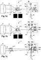
- the figure 1a shows a schematic representation of a first device 1 for implementing a method 100 for spatio-spectral characterization of a polychromatic pulsed laser source.
- the figure 1b shows a schematic representation of a second device 2 for implementing said method 100.
- the figure 1c shows a schematic representation of a third device 3 for implementing said method 100.
- the figure 1d shows a schematic representation of a fourth device 4 for implementing said method 100.
- the figure 1e shows a schematic representation of a fifth device 5 for implementing said method 100.
- the polychromatic pulsed laser source 12 emits a beam 13 comprising a plurality of laser pulses of spectral width ⁇ ⁇ in a direction of propagation z.
- the polychromatic pulsed laser source 12 may for example be a CPA laser source (standing for "chirped pulse amplification ”) Titanium-Sapphire or a parametric amplifier. These illustrative examples are of course not limiting.
- the beam 13 is typically attenuated so that its intensity on the optics of the imaging system is sufficiently low to avoid any distortion effect of thermal or non-linear origin.
- an intensity at the focus of less than 10 12 W / cm 2 is sought, preferably less than 10 11 W / cm 2 , even more preferably less than 10 10 W / cm 2 .
- Attenuation can for example be achieved by means of reflections on untreated silica plates, or by transmission in optics of suitable optical density.
- the focusing optic 14 focuses the beam 13 in a focal plane.
- the focal plane is defined as being of coordinates z 0 according to the direction of propagation z.
- the figure 1 represents for simplicity the focusing optic 14 in the form of a lens, but for the considered pulses, which are of wide spectral band and of high power, the focusing optic 14 is typically an off-axis parabolic mirror.
- the imaging system makes it possible to image the beam 13 in a first plane Pz1 with coordinates z1 in the direction of propagation z.
- the distance dz between the first plane Pz1 and the second plane Pz2 is preferably chosen so that the size of the intensity profile measured on the sensor of the camera is approximately two to five times greater in the second plane Pz2 than in the first plane Pz1.
- the distance dz between the first plane Pz1 and the second plane Pz2 is preferably included in the interval [z R ; 10z R ], and for example equal to 2z R or 5z R.
- the beam 13 risks having, in the second plane Pz2, dimensions that are too large to be able to be easily imaged. If the distance dz between the first plane Pz1 and the second plane Pz2 is less than z R , the amplitude profile of the beam 13 risks not varying enough between the first and second planes Pz1, Pz2 to allow quality characterization.
- the choice of the distance between the different planes is advantageously carried out by taking account of the expected couplings: the planes will be spaced all the more apart as the couplings are assumed to be important.
- the imaging system also makes it possible to image the beam 13 in a third plane Pz3, the first plane Pz1 being arranged between the second plane Pz2 and the third plane Pz3.
- the distance dz 'between the first plane Pz1 and the third plane Pz3 is preferably chosen so that the size of the profile d' intensity measured on the camera sensor is approximately two to five times greater in the third plane Pz3 than in the foreground Pz1.
- the distance dz 'between the first plane Pz1 and the third plane Pz3 is preferably included in the interval [z R ; 10z R ], and for example equal to 2z R or 5z R.
- the focal plane z 0 is determined at the place where the size of the beam on the sensor of the camera 16 is the smallest.
- the imaging system preferably comprises a microscope objective 17 producing an enlarged image of the focal spot on the camera 16 and in In this case, the amplitude division interferometer 18 is arranged between the microscope objective 17 and the camera 16.
- the figures 1a and 1b illustrate such a configuration: the first device 1 and the second device 2 each include a microscope objective 17 in their imaging system. If the focal spot is of large size, that is to say with a diameter greater than 200 ⁇ m, it can be directly imaged by the camera 16 placed at the focus or near the focus.
- the amplitude division interferometer 18 is located between the focusing optics 14 and the focal plane z 0 .
- the figure 1c illustrates such a configuration: the imaging system of the third device 3 does not include a microscope objective.
- Camera 16 is typically a digital sensor camera such as a camera with a CCD sensor (standing for “charge-coupled device”) or a camera with a CMOS sensor (standing for “complementary metal-oxide-semiconductor”). ").
- the focusing optics 14 and / or, where appropriate, the microscope objective 17 can be precisely moved along the direction of propagation z, with a precision of the order of 1 to 10 ⁇ m typically, for example by means of a piezoelectric stage or of a mechanical stage motorized with a stepping motor.
- different planes of the beam can be imaged in the focal plane or near the focal plane by means of a deformable mirror arranged before the focusing optic 14.
- the imaging system itself should not introduce spatio-spectral couplings, nor thermal or non-linear distortions in the beam 13.
- the amplitude division interferometer 18 comprises a splitter and recombination optic, a first optical arm 18a and a second optical arm 18b.
- the first optical arm 18a makes it possible to obtain a first replica 13a of the beam 13 while the second optical arm 18b makes it possible to obtain a second replica 13b of the beam 13.
- the splitter optic and of recombination is referenced 18-L
- the first optical arm 18a comprises a single mirror Ma
- the second optical arm 18b comprises a single mirror Mb.
- the separating and recombining optics is also referenced 18-L
- the first optical arm 18a comprises first and second mirrors Ma1 and Ma2
- the second optical arm 18b comprises first and second mirrors Mb1 and Mb2.
- the first and second optical arms 18a, 18b can be delayed with respect to each other while maintaining their alignment, by precisely moving the one or more mirrors of the second optical arm 18b along the direction of the incident beam thanks to a stage 18-P, which is for example a piezoelectric stage or a motorized mechanical stage with a stepping motor.
- the mirror or mirrors of the second optical arm 18b can be moved along the direction of the incident beam z with an accuracy of at least ⁇ min / 10, preferably ⁇ min / 50 even more preferably ⁇ min / 100, with ⁇ min la smallest beam wavelength 13.
- An angle can be introduced between the first and second optical arms 18a, 18b of the interferometer of the second and third devices 2 and 3, while maintaining a spatial superposition of the first and second replicas 13a, 13b on the camera 16 of the imaging system, by means of the first and second mirrors Ma1, Ma2 of the first optical arm 18a and of the first and second mirrors Mb1, Mb2 of the second optical arm 18b.
- the angle between the first and second optical arms 18a, 18b of the interferometer of the second and third devices 2 and 3 is preferably introduced by means of the first and second mirrors Ma1, Ma2 of the first optical arm 18a, while the first and second Mirrors Mb1, Mb2 of the second optical arm 18b are used to ensure the spatial superposition of the first and second replicas 13a, 13b on the camera 16 of the imaging system.
- the amplitude division interferometer 18 of the figures 1a, 1b and 1c is preferably a Mach-Zehnder type interferometer.
- the amplitude division interferometer 18 of the figures 1a, 1b and 1c could be a Michelson type interferometer.
- the figure 1a illustrates in particular an embodiment of the invention according to which the amplitude division interferometer is configured as an air space, so that its first and second arms 18a, 18b do not have any angle between them and that the patterns of spatial interference obtained during a recombination of the first and second replicas are rings of spatial interference.
- the amplitude division interferometer 18 is however configured as an air wedge, so that its first and second arms 18a, 18b have an angle between them and that the spatial interference patterns obtained during a recombination of the first and second aftershocks are spatial interference fringes.
- the angle between the first and second arms 18a, 18b of the amplitude division interferometer 18 is preferably chosen so that each spatial interference fringe extends over at least two pixels of the camera 16. The more the the angle is greater, the narrower the spatial interference fringes.
- the optical separating function is performed by a birefringent material or crystal, that is to say the optical properties of which are anisotropic.
- a birefringent material or crystal that is to say the optical properties of which are anisotropic.
- Different polarization components of a light ray propagating in a birefringent crystal "see" different refractive indices and therefore propagate at different phase and group speeds. Consequently, these different polarization components are delayed between them at the output of the crystal.
- the two arms have the same refractive index but a different optical path length.
- the two arms have the same optical path length but a different refractive index.
- a uniaxial crystal is used (quartz, alpha-BBO or calcite for example), that is to say having a single axis, called the "optical axis", governing the optical anisotropy, all directions perpendicular or to a single axis. given angle of the optical axis being optically equivalent.
- the rotation of a uniaxial crystal around the optical axis does not modify its optical behavior.
- a uniaxial crystal has two main distinct refractive indices generally referred to as ordinary n e and extraordinary n o indices. Light whose polarization is perpendicular to the optical axis sees the ordinary index n o . Light whose polarization is in the direction of the optical axis sees the extraordinary index n e .
- the zero delay corresponds to the passage of the beam 13 through the center of the first assembly, when the beam 13 passes through exactly the same thickness of the first prism 18-Pr1 and of the second prism 18-Pr2.
- the delay between the two arms can be controlled with great precision, down to a few attoseconds.
- pris is understood here to mean a blade with non-parallel faces (generally translated as “wedge” in English for those skilled in the art).
- the first and second prisms 18-Pr1, 18-Pr2 are made from the same type of uniaxial birefringent material and with their optical axes perpendicular.
- the optical axis of the first prism 18-Pr1 is normal to the plane of the sheet while the optical axis of the second prism 18-Pr2 is in the plane of the sheet, perpendicular to the direction of propagation z.
- the beam 13 at the input of the first assembly has a first component of non-zero polarization along the optical axis of the first prism 18-Pr1 and a second component of non-zero polarization along the optical axis of the second prism 18 -Pr2.
- the first and second non-zero components are preferably balanced with each other.
- a first polarization optic 18-E1 by example a polarizer or a delay plate such as a half-wave plate or a quarter-wave plate, could be arranged on the path of the beam 13 between the source and the first assembly, in order to obtain first and second components non-zero and preferably balanced while optimizing the optical assembly.
- the first polarization optic 18-E1 is provided to modify the direction of polarization so that it is always perpendicular to the direction of propagation z but outside the plane of the sheet, so that it has the first and second non-zero components; the first polarization optic 18-E1 preferably being chosen and arranged to rotate the direction of polarization by 45 ° in order to balance the first and second components.
- a first replica 13a of the beam 13 is obtained, corresponding to the first polarization component; and a second replica 13b of the beam 13, corresponding to the second polarization component.
- These first and second replicas are recombined by means of a polarizer 18-E2 which selects a single direction of polarization, preferably the direction corresponding to the bisector of the first and second components so that 50% of the energy of each component is selected.
- An improvement of the fourth device 4 of the figure 1d is offered with the fifth device 5 of the figure 1e .
- a second assembly of a third prism 18-Pr3 and d 'a fourth prism 18-Pr4 contiguous is provided.
- the first assembly is mobile thanks to the 18-P plate while the second assembly is fixed.
- the third and fourth prisms 18-Pr3, 18-Pr4 are made of the same type of uniaxial birefringent material as the first and second prisms 18-Pr1, 18-Pr2 and with the same angle as the first and second prisms 18-Pr1, 18-Pr2.
- the optical axis of the third prism 18-Pr3 is chosen identical to the optical axis of the first prism 18-Pr1; the optical axis of the fourth prism 18-Pr4 is chosen identical to the optical axis of the second prism 18-Pr2.
- the first assembly having a first interface plane between the first and second prisms 18-Pr1, 18-Pr2 joined together, and the second assembly having a second interface plane between the third and fourth prisms 18-Pr3, 18-Pr4 joined together
- the second assembly is arranged "head-to-tail" with respect to the first assembly, that is to say so that the first and second interface planes are not mutually parallel and, on the contrary, have reverse slopes.
- the first and second assemblies may have the same sizing or a different sizing; the second fixed assembly can in particular be smaller than the first mobile assembly in order to reduce the cost of the assembly.
- An autocorrelated mirror M is arranged at the output of the second assembly, or alternatively a reflecting treatment is provided on the output face of the second assembly, so that the light follows a forward path through the polarizer 18-E2, the first polarization optic. 18-E1 optional if applicable, and the first and second assemblies; then a return path through the second and first assemblies, the first optional polarization optic 18-E1 if applicable, and the polarizer 18-E2.
- the polarizer 18-E2 is a polarizing prism, for example a Glan-Thompson prism, which reflects a polarization component and transmits another polarization component: for the application of the invention, it is a question of allowing all the light of the outward path so as not to disturb the outward path, and to deflect part of the light of the return path towards the camera 16.
- the light of the return path cannot be entirely deflected towards the camera 16 because the two replicas 13a, 13b of the beam 13 which reach the polarizer 18-E2 after the outward and return paths through the first and second assemblies have crossed polarizations, which the polarizer 18-E2 allows to project on the common axis - preferably the bisector of the two polarizations - so that they can interfere.
- the use of the first and second assemblies of prisms in series, of which the first and second interface planes have an inverted slope, has the advantage that the delay induced between the two arms no longer depends on the entry position of the beam. 13. This avoids any possible spatial disturbance or fluctuation ("jitter" in English) of the source 12.
- the use of the first and second assemblies of prisms in series, with the same angle for the four prisms 18- Pr1, 18-Pr2, 18-Pr3, 18-Pr4 also has the advantage of compensating for the angular dispersion or chromatic distortion induced by the first assembly, due to the refraction and the dispersive nature of the medium on broad spectrum pulses. Thus, all the spectral components remain very parallel to each other at the output of the first and second assemblies.
- the use of the first and second assemblies of prisms in series has the advantage that any spatial shift between the two arms induced by the first passage of the outward path, due to the refraction at the interfaces which is different for the two components of polarization, is exactly compensated by the second passage of the return path.
- the two polarization components remain spatially superimposed with one another at the output of the first and second assemblies.
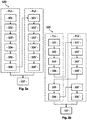
- the figures 2a and 2b respectively show first and second diagrams of the steps of the process 100 for spatio-spectral characterization of a polychromatic pulsed laser source, by means of the device 1 previously described in connection with the figure 1 .
- the first diagram of the figure 2a shows a first possible order for the different steps of the process 100
- the second diagram of the figure 2b shows a second possible order for the different steps of the method 100.
- the time step dt is chosen as a function of the spectral width ⁇ , so that: dt ⁇ ⁇ ⁇ ⁇
- the time step dt is chosen as a function of the spectral width ⁇ , of way that: dt ⁇ 2 ⁇ ⁇ ⁇
- the amplitude division interferometer 18 is configured as an air wedge and the 3D Fourier transform of the space-time interferogram is calculated, it is advantageously possible to use a sampling frequency lower than the frequency minimum sampling required according to the Nyquist in an air knife configuration, without introducing spectral overlap. Further explanations are provided later, in connection with the figures 4a, 4b, 4c in the case of an air gap configuration, and with the figures 5a, 5b, 5c in the case of an air wedge configuration.
- an inverse 2D Fourier transform is carried out in order to go from space ( ⁇ , k x , k y ) to space ( ⁇ , x, y) .
- the figure 3a schematically shows a plurality of images of a plane of the beam 13 of the polychromatic pulsed laser source 12, obtained for different delays ⁇ between first and second replicas 13a, 13b of the beam, according to the fourth step 104, 104 'of the method 100
- the plurality of images is for example a plurality of first images Im1 of the first plane Pz1 of the beam or a plurality of second images Im2 of the second plane Pz2 of the beam or a plurality of images of any other plane of the beam that one has decides to image.
- the temporal interferogram comprises the intensity information at this particular spatial point, as a function of the delay ⁇ .
- the space-time interferogram comprises the amplitude information at all the spatial points of the imaged plane and as a function of the delay ⁇ .
- the figure 3c shows the 1D Fourier transform S ( ⁇ ) in the frequency domain of the time interferogram S ( ⁇ ) of the figure 3b , obtained according to the sixth step 106, 106 ′ of the method 100.
- the spectral support width ⁇ is the difference between the maximum frequency ⁇ max and the minimum frequency ⁇ min of the 1D Fourier transform S ( ⁇ ).
- the width of the lateral frequency peak centered at + ⁇ L is defined as being the spectral width ⁇ of the 1D Fourier transform S ( ⁇ ).
- the sampling frequency ⁇ ech must in particular respect the following criterion: ⁇ ech ⁇ 2 ⁇ ⁇
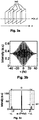
- the figure 4a shows a two-dimensional representation, according to a temporal dimension ⁇ and a first spatial dimension x, of an autocorrelation signal S (x, y, ⁇ ) resolved according to the first spatial dimension x and according to a second spatial dimension y, in the case where, at the output of the interferometer, the first and second replicas 13a, 13b are collinear with each other, that is to say in the case where no angle is introduced between the first and second replicas 13a and 13b .
- the sampling frequency ⁇ ech must also respect the following criterion: ⁇ ech ⁇ 2 ⁇ ⁇
- the figure 4b shows a two-dimensional representation, according to a dimension of temporal frequency ⁇ and the first spatial dimension x, of the 1D Fourier transform S (x, y, ⁇ ) of the autocorrelation signal S (x, y, ⁇ ), for a sampling frequency ⁇ ech greater than the spectral support width ⁇ : ⁇ ech > 2 ⁇
- the figure 5a shows a two-dimensional representation, according to a temporal dimension ⁇ and a first spatial dimension x, of an autocorrelation signal S (x, y, ⁇ ) resolved according to the first spatial dimension x and according to a second spatial dimension y, in the case where, at the output of the interferometer, the first and second replicas 13a, 13b are not collinear with each other, that is to say in the case where an angle ⁇ is introduced between the first and second replicas 13a and 13b.
- the sampling frequency ⁇ ech must simply respect the following criterion: ⁇ ech ⁇ ⁇
- the figure 5b shows a two-dimensional representation, according to a dimension of temporal frequency ⁇ and a dimension of spatial frequency k x , of the 3D Fourier transform S (k x , k y , ⁇ ) of the autocorrelation signal S (x, y, ⁇ ), for a sampling frequency ⁇ ech greater than the spectral support width ⁇ : ⁇ ech > ⁇
- E (t, r) e i ⁇ L t E ′ t r
- J ⁇ r e i ⁇ L ⁇ ⁇ E ′ t r E ′ ⁇ t - ⁇ , r dt
- the spectral intensity is thus obtained at any spatial point of the imaged plane considered, which one chooses to consider as being the spatial intensity at each frequency of the beam.
- the spatial amplitude at each frequency of the beam is then obtained by calculating the square root of this spatial intensity at each frequency of the beam.
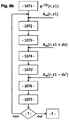
- the method 100 then comprises, for each frequency of the beam 13 of the polychromatic pulsed laser source 12, a seventh step 107 for reconstructing the spatial profile of the phase resolved in frequency, by means of 'a spatial phase reconstruction algorithm.
- At least two separate frequency resolved spatial amplitude profiles are required as input data to a spatial phase reconstruction algorithm.
- providing two separate amplitude spatial profiles resolved in frequency is sufficient to allow the convergence of a spatial phase reconstruction algorithm, i.e. it is unnecessary to provide more than two spatial profiles d 'distinct amplitude resolved in frequency.
- the spatial phase reconstruction algorithm converges better, with better robustness, when three separate frequency-resolved spatial amplitude profiles are provided as input data, rather than two. It is therefore also preferred to carry out, for the third plane Pz3 of the beam 13, the first, second, third, fourth, fifth and sixth steps previously described for the first and second planes Pz1, Pz2 of the beam 13.
- the seventh step 107 of reconstructing the frequency-resolved spatial phase profile is performed by means of a known spatial phase reconstruction algorithm, which makes use of the fact that when a monochromatic laser beam propagates along the propagation direction z , the evolution of his profile transverse amplitude along the direction of propagation z is partly determined by its transverse phase profile.
- a known spatial phase reconstruction algorithm work only for monochromatic laser beams, that is to say having a single frequency. In the case where the polychromatic beam 13 has couplings, it is not possible to directly apply such a spatial phase reconstruction algorithm to it.
- the spatial phase reconstruction algorithm is therefore applied separately to each frequency of the laser beam 13: for each frequency of the beam 13, the first and second spatial profiles of amplitude A m (r, z1) and A m (r , z1 + dz) at said frequency to determine the transverse phase profile ⁇ ( r ) at said frequency.
- a first example of a spatial phase reconstruction algorithm from two spatial amplitude profiles is described in connection with the figure 6a .
- a step T of testing a merit function which is for example the normalized quadratic distance between the amplitudes of the measured and calculated images is then carried out: in practice, one typically decides to stop the algorithm when the normalized quadratic distance n ' evolves more from one iteration to another, that is to say when the normalized quadratic distance stops decreasing from one iteration to another.
- the merit function can also be used to evaluate the quality of the result obtained, that is to say to evaluate whether the spatial amplitude profile calculated at the end of the fifth step 1075 is sufficiently close to the measured amplitude.
- the spatial phase reconstruction algorithm ends.
- the associated phase profile is then considered correct and conserved, and according to step F previously described, the spatial phase reconstruction algorithm ends.
- phase reconstruction algorithms can be used. Such algorithms are for example described in the article “Phase retrieval algorithms: a comparison”, JR Fienup, Applied Optics (1982 ) and in the article “Phase retrieval with application to optical imaging”, Y. Shechtman et al., IEEE Signal Processing Magazine (2015 ).
- the frequency peaks mentioned in the reciprocal image are each associated with a certain spatial frequency.
Landscapes
- Physics & Mathematics (AREA)
- Spectroscopy & Molecular Physics (AREA)
- General Physics & Mathematics (AREA)
- Spectrometry And Color Measurement (AREA)
Claims (10)
- Spektral-räumliches Charakterisierungsverfahren (100) einer polychromatischen Impuls-Laserquelle in einer Vorrichtung (1), umfassend:- eine polychromatische Impuls-Laserquelle (12), die ein Strahlenbündel (13) ausgibt, das eine Vielzahl von Laserimpulsen mit einer Spektralbreite ΔΩ in einer Verbreitungsrichtung z umfasst;- eine optische Fokalisierung (14), die den Strahl (13) in einer fokalen Ebene in z0 fokalisiert;- ein Abbildungssystem zum Abbilden einer ersten Ebene (Pz1) des Strahlenbündels in z1 in der Nähe der fokalen Ebene z0 und einer zweiten Ebene (Pz2) des Strahlenbündels in z1 + dz, wobei das Abbildungssystem wenigstens eine Kamera (16) umfasst;- ein Interferometer mit Amplitudendivision (18), das zwischen der Fokalisierungsoptik (14) und der Kamera (16) angeordnet ist und erste und zweite Arme (18a, 18b) aufweist;wobei das Verfahren (100) für jede der ersten (Pz1) und der zweiten (Pz2) Ebene des Strahlenbündels die folgenden Schritte umfasst:- Abbilden (101, 101') der Ebene (Pz1, Pz2) des Strahlenbündels (13) mittels des Abbildungssystems;- Erstellen (102, 102') der ersten und der zweiten Nachbildung (13a, 13b) des Strahlenbündels (13) mittels des ersten und des zweiten Arms (18a, 18b) des Interferometers mit Amplitudendivision (18);- Rekombinieren (103, 103') der ersten und der zweiten Replik (13a, 13b) des Strahlenbündels (13) auf der Kamera (16) des Abbildungssystems derart, dass ein Bild (Im1, Im2) in zwei räumlichen Dimensionen mit räumlichen Interferenzmustern erhalten wird;- Messen (104, 104') dieses Bildes in Abhängigkeit von einer Frist T zwischen der ersten und der zweiten Nachbildung, wobei die Frist T ein Zeitintervall Δt mit einem Schritt dt für den Erhalt eines zeitlichen Interferogramms in jedem räumlichen Punkt des Bildes (Im1, Im2) abtastet, wobei alle zeitlichen Interferogramme ein räumlich-zeitliches Interferogramm bilden;- Berechnen (105, 105') der Fourier-Transformierten 1D jedes zeitlichen Interferogramms oder der Fourier-Transformierten ID des räumlich-zeitlichen Interferogramms, wobei die genannte Fourier-Transformierte eine zentrale Frequenzspitze und zwei seitliche Frequenzspitzen umfasst;- Filtern (106, 106') der genannten Fourier-Transformierten derart, dass nur eine der zwei seitlichen Frequenzspitzen behalten wird;wobei das Verfahren (100) anschließend für jede Frequenz der polychromatischen Impuls-Laserquelle (12) einen Wiederaufbauschritt (107) des räumlichen Phasenprofils, der ausgehend von einem ersten, in der Frequenz aufgelösten räumlichen Amplitudenprofil in der Frequenz aufgelöst ist, das für die erste Ebene (Pz1) des Strahlenbündels erhalten wird, und einem zweiten, in der Frequenz aufgelösten räumlichen Amplitudenprofil, das für die zweite Ebene (Pz2) des Strahlenbündels erhalten wird, umfasst.
- Spektral-räumliches Charakterisierungsverfahren (100) gemäß Anspruch 1, dadurch gekennzeichnet, dass das Interferometer mit Amplitudendivision (18) derart als Luftkeil ausgestaltet ist, dass sein erster und sein zweiter Arm (18a, 18b) untereinander einen Winkel aufweisen und dass die räumlichen Interferenzmuster, die bei der Rekombination der ersten und der zweiten Nachbildung (13a, 13b) des Strahlenbündels (13) auf der Kamera (16) des Abbildungssystems erhalten werden, räumliche Interferenzstreifen sind.
- Spektral-räumliches Charakterisierungsverfahren (100) gemäß Anspruch 2, dadurch gekennzeichnet, dass es im Übrigen für jedes Bild (Im1, Im2), das räumliche Interferenzstreifen aufweist, die folgenden Schritte umfasst:- Berechnen der räumlichen Fourier-Transformierten mit zwei Abmessungen des genannten Bildes derart, dass ein beiderseitiges Bild erhalten wird, das eine zentrale Frequenzspitze und zwei seitliche Frequenzspitzen umfasst;- Ändern des beiderseitigen Bildes dank der Eigenschaften der zentralen Frequenzspitze;- Berechnen der umgekehrten räumlichen Fourier-Transformierten des abgeänderten beiderseitigen Bildes derart, dass es in den ursprünglichen Raum zurückkehrt.
- Spektral-räumliches Charakterisierungsverfahren (100) gemäß Anspruch 3, dadurch gekennzeichnet, dass der Winkel zwischen dem ersten und dem zweiten Arm (18a, 18b) des Interferometers mit Amplitudendivision (18) derart ausgewählt ist, dass jeder räumliche Interferenzstreifen sich über wenigstens zwei Pixel der Kamera (16) erstreckt.
- Spektral-räumliches Charakterisierungsverfahren (100) gemäß irgendeinem der Ansprüche 2 bis 4, dadurch gekennzeichnet, dass der Schritt dt derart ausgewählt ist, dass

- Spektral-räumliches Charakterisierungsverfahren (100) gemäß irgendeinem der voranstehenden Ansprüche, dadurch gekennzeichnet, dass das Interferometer mit Amplitudendivision (18) ein Interferometer vom Typ Mach-Zehnder ist.
- Spektral-räumliches Charakterisierungsverfahren (100) gemäß Anspruch 1, dadurch gekennzeichnet, dass der erste und der zweite Arm (18a, 18b) des Interferometers mit Amplitudendivision (18) eine und dieselbe optische Weglänge und einen unterschiedlichen Brechungsindex aufweisen.
- Spektral-räumliches Charakterisierungsverfahren (100) gemäß dem voranstehenden Anspruch, dadurch gekennzeichnet, dass in dem Interferometer mit Amplitudendivision (18) eine trennende optische Funktion durch ein doppelbrechendes Material (18-Pr1, 18-Pr2, 18-Pr3, 18-Pr4) gewährleistet ist und eine optische Rekombinationsfunktion durch einen Polarisierer (18-E2) gewährleistet ist.
- Spektral-räumliches Charakterisierungsverfahren (100) gemäß irgendeinem der Ansprüche 7 oder 8, dadurch gekennzeichnet, dass das Interferometer mit Amplitudendivision (18) eine erste Gruppe eines ersten Prismas (18-Pr1) und eines zweiten Prismas (18-Pr2) umfasst, die aneinander angebaut, aus einem und demselben einachsigen doppelbrechenden Materialtyp realisiert sind und deren optische Achsen lotrecht sind, wobei die erste Gruppe auf einer Platine (18-P) angeordnet ist, um eine Frist zwischen dem ersten und dem zweiten Arm (18a, 18b) des Interferometers mit Amplitudendivision (18) zu kontrollieren.
- Spektral-räumliches Charakterisierungsverfahren (100) gemäß dem voranstehenden Anspruch, dadurch gekennzeichnet, dass:- das Interferometer mit Amplitudendivision eine zweite Gruppe eines dritten Prismas (18-Pr3) und eines vierten Prismas (18-Pr4) umfasst, die aneinander angebaut, aus einem und demselben einachsigen doppelbrechenden Materialtyp und mit demselben Winkel wie das erste und das zweite Prisma (18-Pr1, 18-Prs) realisiert sind; wobei die optische Achse des dritten Prismas (18-Pr3) mit der optischen Achse des ersten Prismas (18-Pr1) identisch ist und die optische Achse des vierten Prismas (18-Pr4) mit der optischen Achse des zweiten Prismas (18-Pr2) identisch ist; wobei die erste Gruppe eine erste Interferenzebene zwischen dem ersten und dem zweiten Prisma (18-Pr1, 18-Pr2), die aneinander angebaut sind, aufweist, und die zweite Gruppe eine zweite Interferenzeben zwischen dem dritten und dem vierten Prisma (18-Pr3, 18-Pr4), die aneinander angebaut sind, aufweist, wobei die zweite Gruppe in Bezug auf die erste Gruppe derart angeordnet ist, dass die erste und die zweite Interferenzebene zueinander nicht parallel sind und stattdessen umgekehrte Neigungen aufweisen; und- das Strahlenbündel (13) einen Hinweg durch die erste und die zweite Gruppe und einen Rückweg durch die zweite und die erste Gruppe durchläuft.
Applications Claiming Priority (2)
| Application Number | Priority Date | Filing Date | Title |
|---|---|---|---|
| FR1753672A FR3065805B1 (fr) | 2017-04-27 | 2017-04-27 | Procede de caracterisation spatio-spectrale d’une source laser impulsionnelle polychromatique |
| PCT/EP2018/060679 WO2018197599A1 (fr) | 2017-04-27 | 2018-04-26 | Procede de caracterisation spatio-spectrale d'une source laser impulsionnelle polychromatique |
Publications (2)
| Publication Number | Publication Date |
|---|---|
| EP3615902A1 EP3615902A1 (de) | 2020-03-04 |
| EP3615902B1 true EP3615902B1 (de) | 2021-04-14 |
Family
ID=60019962
Family Applications (1)
| Application Number | Title | Priority Date | Filing Date |
|---|---|---|---|
| EP18722433.2A Active EP3615902B1 (de) | 2017-04-27 | 2018-04-26 | Verfahren zur räumlich-spektralen charakterisierung einer polychromatischen gepulsten laserquelle |
Country Status (4)
| Country | Link |
|---|---|
| EP (1) | EP3615902B1 (de) |
| FR (1) | FR3065805B1 (de) |
| HU (1) | HUE055493T2 (de) |
| WO (1) | WO2018197599A1 (de) |
Families Citing this family (1)
| Publication number | Priority date | Publication date | Assignee | Title |
|---|---|---|---|---|
| JP7326972B2 (ja) * | 2019-07-30 | 2023-08-16 | 株式会社リコー | 表面特性評価方法、表面特性評価装置、及び表面特性評価プログラム |
Family Cites Families (1)
| Publication number | Priority date | Publication date | Assignee | Title |
|---|---|---|---|---|
| FR3022346B1 (fr) * | 2014-06-16 | 2022-10-07 | Commissariat Energie Atomique | Dispositif et procede de caracterisation d'un faisceau de lumiere |
-
2017
- 2017-04-27 FR FR1753672A patent/FR3065805B1/fr active Active
-
2018
- 2018-04-26 HU HUE18722433A patent/HUE055493T2/hu unknown
- 2018-04-26 WO PCT/EP2018/060679 patent/WO2018197599A1/fr unknown
- 2018-04-26 EP EP18722433.2A patent/EP3615902B1/de active Active
Non-Patent Citations (1)
| Title |
|---|
| None * |
Also Published As
| Publication number | Publication date |
|---|---|
| HUE055493T2 (hu) | 2021-12-28 |
| EP3615902A1 (de) | 2020-03-04 |
| FR3065805B1 (fr) | 2019-06-28 |
| FR3065805A1 (fr) | 2018-11-02 |
| WO2018197599A1 (fr) | 2018-11-01 |
Similar Documents
| Publication | Publication Date | Title |
|---|---|---|
| EP3155385B1 (de) | Vorrichtung und verfahren zur charakterisierung eines lichtstrahls | |
| EP3824269B1 (de) | Verfahren und systeme zur nichtinvasiven optischen charakterisierung eines heterogenen mediums | |
| EP3345264B1 (de) | System zur messung der dauer, des zeitlichen profils und spektrums eines ultraschnellen laserpulses | |
| WO2010089511A1 (fr) | Dispositif autocorrelateur a biprisme pour la mesure temporelle d'impulsions de lumiere ultrabreves | |
| EP3615902B1 (de) | Verfahren zur räumlich-spektralen charakterisierung einer polychromatischen gepulsten laserquelle | |
| EP2075556B1 (de) | Verfahren und Vorrichtung zum Messen der Spektralphase oder der Kombination aus Spektralphase und räumlicher Phase von ultrakurzen Lichtimpulsen | |
| FR3064760B1 (fr) | Interferometre holographique numerique a deux faisceaux de reference pour analyser un milieu transparent | |
| EP3416250A1 (de) | Verfahren und lasersystem zum steuern der laufzeitgeschwindigkeit von ausgesendeten laserpulsen | |
| EP2721385A1 (de) | Vorrichtung und verfahren zur charakterisierung eines lichtstrahls | |
| EP3644032A1 (de) | Bildgebender spektrometer und optische einzelpunkt-autokorrelationsvorrichtung, die einen solchen bildgebenden spektrometer umfasst | |
| EP2520916A1 (de) | Multispektrales Scanteleskop mit Wellenfrontanalysemitteln. | |
| FR3034577A1 (fr) | Dispositif et procede de caracterisation d’une impulsion laser femtoseconde | |
| WO2021152161A4 (fr) | Dispositif et procédé de diagnostic de la compressibilité au foyer d'une impulsion ultra-brève à partir de données spatio-spectrales de l'impulsion ayant subi un effet non linéaire | |
| EP2708862B1 (de) | Optischer Wellenfrontanalysator | |
| EP3679424B1 (de) | Verbessertes frequenzumwandlungssystem | |
| FR3059156B1 (fr) | Module de detection optique | |
| FR3004253A1 (fr) | Procede de mesure de front d'onde a grande sensibilite et mesureur correspondant | |
| WO2024017670A1 (fr) | Procédés et systèmes de caractérisation optique d'un milieu volumique et diffusant | |
| WO2022117927A1 (fr) | Caracterisation d'une impulsion de rayonnement par fenetrage optique resolu en temps | |
| EP1480028A1 (de) | Verfahren und Vorrichtung zur Charakterisierung von optischen Impulsen | |
| FR2841649A1 (fr) | Procede et systeme de determination du profil de la phase spectrale ou temporelle d'une impulsion d'energie electromagnetique |
Legal Events
| Date | Code | Title | Description |
|---|---|---|---|
| STAA | Information on the status of an ep patent application or granted ep patent |
Free format text: STATUS: UNKNOWN |
|
| STAA | Information on the status of an ep patent application or granted ep patent |
Free format text: STATUS: THE INTERNATIONAL PUBLICATION HAS BEEN MADE |
|
| PUAI | Public reference made under article 153(3) epc to a published international application that has entered the european phase |
Free format text: ORIGINAL CODE: 0009012 |
|
| STAA | Information on the status of an ep patent application or granted ep patent |
Free format text: STATUS: REQUEST FOR EXAMINATION WAS MADE |
|
| 17P | Request for examination filed |
Effective date: 20191028 |
|
| AK | Designated contracting states |
Kind code of ref document: A1 Designated state(s): AL AT BE BG CH CY CZ DE DK EE ES FI FR GB GR HR HU IE IS IT LI LT LU LV MC MK MT NL NO PL PT RO RS SE SI SK SM TR |
|
| AX | Request for extension of the european patent |
Extension state: BA ME |
|
| DAV | Request for validation of the european patent (deleted) | ||
| DAX | Request for extension of the european patent (deleted) | ||
| RIC1 | Information provided on ipc code assigned before grant |
Ipc: G01J 1/42 20060101ALI20200728BHEP Ipc: G01J 11/00 20060101ALI20200728BHEP Ipc: G01J 9/02 20060101AFI20200728BHEP |
|
| GRAP | Despatch of communication of intention to grant a patent |
Free format text: ORIGINAL CODE: EPIDOSNIGR1 |
|
| STAA | Information on the status of an ep patent application or granted ep patent |
Free format text: STATUS: GRANT OF PATENT IS INTENDED |
|
| INTG | Intention to grant announced |
Effective date: 20201027 |
|
| GRAS | Grant fee paid |
Free format text: ORIGINAL CODE: EPIDOSNIGR3 |
|
| GRAA | (expected) grant |
Free format text: ORIGINAL CODE: 0009210 |
|
| STAA | Information on the status of an ep patent application or granted ep patent |
Free format text: STATUS: THE PATENT HAS BEEN GRANTED |
|
| AK | Designated contracting states |
Kind code of ref document: B1 Designated state(s): AL AT BE BG CH CY CZ DE DK EE ES FI FR GB GR HR HU IE IS IT LI LT LU LV MC MK MT NL NO PL PT RO RS SE SI SK SM TR |
|
| REG | Reference to a national code |
Ref country code: GB Ref legal event code: FG4D Free format text: NOT ENGLISH |
|
| REG | Reference to a national code |
Ref country code: CH Ref legal event code: EP |
|
| REG | Reference to a national code |
Ref country code: DE Ref legal event code: R096 Ref document number: 602018015548 Country of ref document: DE |
|
| REG | Reference to a national code |
Ref country code: IE Ref legal event code: FG4D Free format text: LANGUAGE OF EP DOCUMENT: FRENCH |
|
| REG | Reference to a national code |
Ref country code: AT Ref legal event code: REF Ref document number: 1382832 Country of ref document: AT Kind code of ref document: T Effective date: 20210515 |
|
| REG | Reference to a national code |
Ref country code: RO Ref legal event code: EPE |
|
| REG | Reference to a national code |
Ref country code: LT Ref legal event code: MG9D |
|
| REG | Reference to a national code |
Ref country code: AT Ref legal event code: MK05 Ref document number: 1382832 Country of ref document: AT Kind code of ref document: T Effective date: 20210414 |
|
| REG | Reference to a national code |
Ref country code: NL Ref legal event code: MP Effective date: 20210414 |
|
| PG25 | Lapsed in a contracting state [announced via postgrant information from national office to epo] |
Ref country code: NL Free format text: LAPSE BECAUSE OF FAILURE TO SUBMIT A TRANSLATION OF THE DESCRIPTION OR TO PAY THE FEE WITHIN THE PRESCRIBED TIME-LIMIT Effective date: 20210414 Ref country code: BG Free format text: LAPSE BECAUSE OF FAILURE TO SUBMIT A TRANSLATION OF THE DESCRIPTION OR TO PAY THE FEE WITHIN THE PRESCRIBED TIME-LIMIT Effective date: 20210714 Ref country code: AT Free format text: LAPSE BECAUSE OF FAILURE TO SUBMIT A TRANSLATION OF THE DESCRIPTION OR TO PAY THE FEE WITHIN THE PRESCRIBED TIME-LIMIT Effective date: 20210414 Ref country code: FI Free format text: LAPSE BECAUSE OF FAILURE TO SUBMIT A TRANSLATION OF THE DESCRIPTION OR TO PAY THE FEE WITHIN THE PRESCRIBED TIME-LIMIT Effective date: 20210414 Ref country code: LT Free format text: LAPSE BECAUSE OF FAILURE TO SUBMIT A TRANSLATION OF THE DESCRIPTION OR TO PAY THE FEE WITHIN THE PRESCRIBED TIME-LIMIT Effective date: 20210414 Ref country code: HR Free format text: LAPSE BECAUSE OF FAILURE TO SUBMIT A TRANSLATION OF THE DESCRIPTION OR TO PAY THE FEE WITHIN THE PRESCRIBED TIME-LIMIT Effective date: 20210414 |
|
| PGFP | Annual fee paid to national office [announced via postgrant information from national office to epo] |
Ref country code: CZ Payment date: 20210616 Year of fee payment: 4 |
|
| PG25 | Lapsed in a contracting state [announced via postgrant information from national office to epo] |
Ref country code: GR Free format text: LAPSE BECAUSE OF FAILURE TO SUBMIT A TRANSLATION OF THE DESCRIPTION OR TO PAY THE FEE WITHIN THE PRESCRIBED TIME-LIMIT Effective date: 20210715 Ref country code: IS Free format text: LAPSE BECAUSE OF FAILURE TO SUBMIT A TRANSLATION OF THE DESCRIPTION OR TO PAY THE FEE WITHIN THE PRESCRIBED TIME-LIMIT Effective date: 20210814 Ref country code: PT Free format text: LAPSE BECAUSE OF FAILURE TO SUBMIT A TRANSLATION OF THE DESCRIPTION OR TO PAY THE FEE WITHIN THE PRESCRIBED TIME-LIMIT Effective date: 20210816 Ref country code: SE Free format text: LAPSE BECAUSE OF FAILURE TO SUBMIT A TRANSLATION OF THE DESCRIPTION OR TO PAY THE FEE WITHIN THE PRESCRIBED TIME-LIMIT Effective date: 20210414 Ref country code: RS Free format text: LAPSE BECAUSE OF FAILURE TO SUBMIT A TRANSLATION OF THE DESCRIPTION OR TO PAY THE FEE WITHIN THE PRESCRIBED TIME-LIMIT Effective date: 20210414 Ref country code: LV Free format text: LAPSE BECAUSE OF FAILURE TO SUBMIT A TRANSLATION OF THE DESCRIPTION OR TO PAY THE FEE WITHIN THE PRESCRIBED TIME-LIMIT Effective date: 20210414 Ref country code: PL Free format text: LAPSE BECAUSE OF FAILURE TO SUBMIT A TRANSLATION OF THE DESCRIPTION OR TO PAY THE FEE WITHIN THE PRESCRIBED TIME-LIMIT Effective date: 20210414 Ref country code: NO Free format text: LAPSE BECAUSE OF FAILURE TO SUBMIT A TRANSLATION OF THE DESCRIPTION OR TO PAY THE FEE WITHIN THE PRESCRIBED TIME-LIMIT Effective date: 20210714 |
|
| PGFP | Annual fee paid to national office [announced via postgrant information from national office to epo] |
Ref country code: HU Payment date: 20210718 Year of fee payment: 4 Ref country code: RO Payment date: 20210617 Year of fee payment: 4 |
|
| REG | Reference to a national code |
Ref country code: HU Ref legal event code: AG4A Ref document number: E055493 Country of ref document: HU |
|
| PG25 | Lapsed in a contracting state [announced via postgrant information from national office to epo] |
Ref country code: LU Free format text: LAPSE BECAUSE OF NON-PAYMENT OF DUE FEES Effective date: 20210426 |
|
| REG | Reference to a national code |
Ref country code: DE Ref legal event code: R097 Ref document number: 602018015548 Country of ref document: DE |
|
| REG | Reference to a national code |
Ref country code: BE Ref legal event code: MM Effective date: 20210430 |
|
| PG25 | Lapsed in a contracting state [announced via postgrant information from national office to epo] |
Ref country code: MC Free format text: LAPSE BECAUSE OF FAILURE TO SUBMIT A TRANSLATION OF THE DESCRIPTION OR TO PAY THE FEE WITHIN THE PRESCRIBED TIME-LIMIT Effective date: 20210414 Ref country code: DK Free format text: LAPSE BECAUSE OF FAILURE TO SUBMIT A TRANSLATION OF THE DESCRIPTION OR TO PAY THE FEE WITHIN THE PRESCRIBED TIME-LIMIT Effective date: 20210414 Ref country code: CH Free format text: LAPSE BECAUSE OF NON-PAYMENT OF DUE FEES Effective date: 20210430 Ref country code: SM Free format text: LAPSE BECAUSE OF FAILURE TO SUBMIT A TRANSLATION OF THE DESCRIPTION OR TO PAY THE FEE WITHIN THE PRESCRIBED TIME-LIMIT Effective date: 20210414 Ref country code: ES Free format text: LAPSE BECAUSE OF FAILURE TO SUBMIT A TRANSLATION OF THE DESCRIPTION OR TO PAY THE FEE WITHIN THE PRESCRIBED TIME-LIMIT Effective date: 20210414 Ref country code: EE Free format text: LAPSE BECAUSE OF FAILURE TO SUBMIT A TRANSLATION OF THE DESCRIPTION OR TO PAY THE FEE WITHIN THE PRESCRIBED TIME-LIMIT Effective date: 20210414 Ref country code: SK Free format text: LAPSE BECAUSE OF FAILURE TO SUBMIT A TRANSLATION OF THE DESCRIPTION OR TO PAY THE FEE WITHIN THE PRESCRIBED TIME-LIMIT Effective date: 20210414 Ref country code: LI Free format text: LAPSE BECAUSE OF NON-PAYMENT OF DUE FEES Effective date: 20210430 |
|
| PLBE | No opposition filed within time limit |
Free format text: ORIGINAL CODE: 0009261 |
|
| STAA | Information on the status of an ep patent application or granted ep patent |
Free format text: STATUS: NO OPPOSITION FILED WITHIN TIME LIMIT |
|
| 26N | No opposition filed |
Effective date: 20220117 |
|
| PG25 | Lapsed in a contracting state [announced via postgrant information from national office to epo] |
Ref country code: IE Free format text: LAPSE BECAUSE OF NON-PAYMENT OF DUE FEES Effective date: 20210426 |
|
| PG25 | Lapsed in a contracting state [announced via postgrant information from national office to epo] |
Ref country code: IS Free format text: LAPSE BECAUSE OF FAILURE TO SUBMIT A TRANSLATION OF THE DESCRIPTION OR TO PAY THE FEE WITHIN THE PRESCRIBED TIME-LIMIT Effective date: 20210814 Ref country code: AL Free format text: LAPSE BECAUSE OF FAILURE TO SUBMIT A TRANSLATION OF THE DESCRIPTION OR TO PAY THE FEE WITHIN THE PRESCRIBED TIME-LIMIT Effective date: 20210414 |
|
| PG25 | Lapsed in a contracting state [announced via postgrant information from national office to epo] |
Ref country code: IT Free format text: LAPSE BECAUSE OF FAILURE TO SUBMIT A TRANSLATION OF THE DESCRIPTION OR TO PAY THE FEE WITHIN THE PRESCRIBED TIME-LIMIT Effective date: 20210414 Ref country code: BE Free format text: LAPSE BECAUSE OF NON-PAYMENT OF DUE FEES Effective date: 20210430 |
|
| PG25 | Lapsed in a contracting state [announced via postgrant information from national office to epo] |
Ref country code: RO Free format text: LAPSE BECAUSE OF NON-PAYMENT OF DUE FEES Effective date: 20220426 Ref country code: HU Free format text: LAPSE BECAUSE OF NON-PAYMENT OF DUE FEES Effective date: 20220427 Ref country code: CZ Free format text: LAPSE BECAUSE OF NON-PAYMENT OF DUE FEES Effective date: 20220426 |
|
| PG25 | Lapsed in a contracting state [announced via postgrant information from national office to epo] |
Ref country code: CY Free format text: LAPSE BECAUSE OF FAILURE TO SUBMIT A TRANSLATION OF THE DESCRIPTION OR TO PAY THE FEE WITHIN THE PRESCRIBED TIME-LIMIT Effective date: 20210414 |
|
| PG25 | Lapsed in a contracting state [announced via postgrant information from national office to epo] |
Ref country code: MK Free format text: LAPSE BECAUSE OF FAILURE TO SUBMIT A TRANSLATION OF THE DESCRIPTION OR TO PAY THE FEE WITHIN THE PRESCRIBED TIME-LIMIT Effective date: 20210414 |
|
| PG25 | Lapsed in a contracting state [announced via postgrant information from national office to epo] |
Ref country code: TR Free format text: LAPSE BECAUSE OF FAILURE TO SUBMIT A TRANSLATION OF THE DESCRIPTION OR TO PAY THE FEE WITHIN THE PRESCRIBED TIME-LIMIT Effective date: 20210414 |
|
| PGFP | Annual fee paid to national office [announced via postgrant information from national office to epo] |
Ref country code: GB Payment date: 20240418 Year of fee payment: 7 |
|
| PGFP | Annual fee paid to national office [announced via postgrant information from national office to epo] |
Ref country code: DE Payment date: 20240418 Year of fee payment: 7 |
|
| PGFP | Annual fee paid to national office [announced via postgrant information from national office to epo] |
Ref country code: FR Payment date: 20240422 Year of fee payment: 7 |
|
| PG25 | Lapsed in a contracting state [announced via postgrant information from national office to epo] |
Ref country code: MT Free format text: LAPSE BECAUSE OF FAILURE TO SUBMIT A TRANSLATION OF THE DESCRIPTION OR TO PAY THE FEE WITHIN THE PRESCRIBED TIME-LIMIT Effective date: 20210414 |