EP3614599B1 - Method used to request system information, apparatus, user equipment and base station - Google Patents
Method used to request system information, apparatus, user equipment and base station Download PDFInfo
- Publication number
- EP3614599B1 EP3614599B1 EP17906580.0A EP17906580A EP3614599B1 EP 3614599 B1 EP3614599 B1 EP 3614599B1 EP 17906580 A EP17906580 A EP 17906580A EP 3614599 B1 EP3614599 B1 EP 3614599B1
- Authority
- EP
- European Patent Office
- Prior art keywords
- system information
- requested
- pilot code
- response message
- requested system
- Prior art date
- Legal status (The legal status is an assumption and is not a legal conclusion. Google has not performed a legal analysis and makes no representation as to the accuracy of the status listed.)
- Active
Links
- 238000000034 method Methods 0.000 title claims description 59
- 230000004044 response Effects 0.000 claims description 142
- 230000005540 biological transmission Effects 0.000 claims description 24
- 238000012544 monitoring process Methods 0.000 claims description 11
- 238000010586 diagram Methods 0.000 description 14
- 238000012545 processing Methods 0.000 description 13
- 238000004891 communication Methods 0.000 description 12
- 238000005516 engineering process Methods 0.000 description 9
- 230000008569 process Effects 0.000 description 5
- 238000001228 spectrum Methods 0.000 description 5
- 230000003287 optical effect Effects 0.000 description 4
- 230000005236 sound signal Effects 0.000 description 4
- 230000000737 periodic effect Effects 0.000 description 3
- 230000001133 acceleration Effects 0.000 description 2
- 230000008859 change Effects 0.000 description 2
- 230000003993 interaction Effects 0.000 description 2
- 230000002093 peripheral effect Effects 0.000 description 2
- 230000003068 static effect Effects 0.000 description 2
- 101100533725 Mus musculus Smr3a gene Proteins 0.000 description 1
- 238000003491 array Methods 0.000 description 1
- 230000009286 beneficial effect Effects 0.000 description 1
- 239000000969 carrier Substances 0.000 description 1
- 230000000295 complement effect Effects 0.000 description 1
- 238000011161 development Methods 0.000 description 1
- 238000003384 imaging method Methods 0.000 description 1
- 239000004973 liquid crystal related substance Substances 0.000 description 1
- 230000007774 longterm Effects 0.000 description 1
- 238000013507 mapping Methods 0.000 description 1
- 238000010295 mobile communication Methods 0.000 description 1
- 238000012986 modification Methods 0.000 description 1
- 230000004048 modification Effects 0.000 description 1
- 238000011160 research Methods 0.000 description 1
- 239000004065 semiconductor Substances 0.000 description 1
- 230000001960 triggered effect Effects 0.000 description 1
Images


Classifications
-
- H—ELECTRICITY
- H04—ELECTRIC COMMUNICATION TECHNIQUE
- H04L—TRANSMISSION OF DIGITAL INFORMATION, e.g. TELEGRAPHIC COMMUNICATION
- H04L5/00—Arrangements affording multiple use of the transmission path
- H04L5/003—Arrangements for allocating sub-channels of the transmission path
- H04L5/0048—Allocation of pilot signals, i.e. of signals known to the receiver
-
- H—ELECTRICITY
- H04—ELECTRIC COMMUNICATION TECHNIQUE
- H04W—WIRELESS COMMUNICATION NETWORKS
- H04W48/00—Access restriction; Network selection; Access point selection
- H04W48/08—Access restriction or access information delivery, e.g. discovery data delivery
- H04W48/14—Access restriction or access information delivery, e.g. discovery data delivery using user query or user detection
-
- H—ELECTRICITY
- H04—ELECTRIC COMMUNICATION TECHNIQUE
- H04W—WIRELESS COMMUNICATION NETWORKS
- H04W52/00—Power management, e.g. TPC [Transmission Power Control], power saving or power classes
- H04W52/02—Power saving arrangements
- H04W52/0203—Power saving arrangements in the radio access network or backbone network of wireless communication networks
- H04W52/0206—Power saving arrangements in the radio access network or backbone network of wireless communication networks in access points, e.g. base stations
-
- H—ELECTRICITY
- H04—ELECTRIC COMMUNICATION TECHNIQUE
- H04W—WIRELESS COMMUNICATION NETWORKS
- H04W48/00—Access restriction; Network selection; Access point selection
- H04W48/16—Discovering, processing access restriction or access information
-
- H—ELECTRICITY
- H04—ELECTRIC COMMUNICATION TECHNIQUE
- H04W—WIRELESS COMMUNICATION NETWORKS
- H04W74/00—Wireless channel access, e.g. scheduled or random access
- H04W74/002—Transmission of channel access control information
- H04W74/006—Transmission of channel access control information in the downlink, i.e. towards the terminal
-
- H—ELECTRICITY
- H04—ELECTRIC COMMUNICATION TECHNIQUE
- H04W—WIRELESS COMMUNICATION NETWORKS
- H04W74/00—Wireless channel access, e.g. scheduled or random access
- H04W74/002—Transmission of channel access control information
- H04W74/008—Transmission of channel access control information with additional processing of random access related information at receiving side
-
- H—ELECTRICITY
- H04—ELECTRIC COMMUNICATION TECHNIQUE
- H04W—WIRELESS COMMUNICATION NETWORKS
- H04W74/00—Wireless channel access, e.g. scheduled or random access
- H04W74/08—Non-scheduled or contention based access, e.g. random access, ALOHA, CSMA [Carrier Sense Multiple Access]
- H04W74/0833—Non-scheduled or contention based access, e.g. random access, ALOHA, CSMA [Carrier Sense Multiple Access] using a random access procedure
-
- H—ELECTRICITY
- H04—ELECTRIC COMMUNICATION TECHNIQUE
- H04W—WIRELESS COMMUNICATION NETWORKS
- H04W76/00—Connection management
- H04W76/20—Manipulation of established connections
- H04W76/27—Transitions between radio resource control [RRC] states
-
- Y—GENERAL TAGGING OF NEW TECHNOLOGICAL DEVELOPMENTS; GENERAL TAGGING OF CROSS-SECTIONAL TECHNOLOGIES SPANNING OVER SEVERAL SECTIONS OF THE IPC; TECHNICAL SUBJECTS COVERED BY FORMER USPC CROSS-REFERENCE ART COLLECTIONS [XRACs] AND DIGESTS
- Y02—TECHNOLOGIES OR APPLICATIONS FOR MITIGATION OR ADAPTATION AGAINST CLIMATE CHANGE
- Y02D—CLIMATE CHANGE MITIGATION TECHNOLOGIES IN INFORMATION AND COMMUNICATION TECHNOLOGIES [ICT], I.E. INFORMATION AND COMMUNICATION TECHNOLOGIES AIMING AT THE REDUCTION OF THEIR OWN ENERGY USE
- Y02D30/00—Reducing energy consumption in communication networks
- Y02D30/70—Reducing energy consumption in communication networks in wireless communication networks
Landscapes
- Engineering & Computer Science (AREA)
- Signal Processing (AREA)
- Computer Networks & Wireless Communication (AREA)
- Computer Security & Cryptography (AREA)
- Mobile Radio Communication Systems (AREA)
- Detection And Prevention Of Errors In Transmission (AREA)
Description
- The present disclosure relates to the field of communication technology, and in particular, to a method for requesting system information, a method for sending system information, a user equipment, and a base station.
- With the rapid development of wireless communication technology, the number of System Information (SI) of Long Term Evolution (LTE) increases, and sending SI of LTE in a periodic broadcast manner may cause more power consumption of a base station and a low utilization rate of spectrum resources. For a case that the number of User Equipment (UE) accessed is relatively less, sending SI of LTE in the periodic broadcast manner wastes resources. To relieve the problems of wasting resources and more power consumption of the base station caused by sending SI of LTE in the broadcast manner, telecom carriers begin to consider the way of sending SI by classification to solve the above problems.
- In a research discussion of the 5th Generation mobile communication technology (5G for short) project, SI may be classified into a first type of SI and a second type of SI. The first type of SI may include SI associated with cell selection and cell access, and the second type of SI may include other SI except for the first type of SI. In the related art, the first type of SI may still be sent by broadcasting, and for the second type of SI, when a particular preamble for requesting the second type of SI sent by the UE through MSG 1 (a first message in a random access process) is received, the second type of SI may be broadcast within a transmission window of the second type of SI requested by the UE. But in the related art, sending the MSG 1 by the UE may fail due to low power for sending the MSG 1, which further causes that the base station does not broadcast the second type of SI because the request message sent by the UE is not received. In this case, the UE may only wait for a next SI period to re-request the second type of SI through the MSG 1, which results in a longer latency for the UE to obtain the SI and thus seriously affecting the performance.
-
WO 2016/198909 A1 discloses a method for low overhead system information acquisition (LOSIA). The LOSIA method ofWO-2016/198909 A1 includes several techniques for transmitting common channels in a next generation Radio Access Technology (xRAT).WO-2016/198909 A1 also discloses that instead of transmitting system information in a periodic, static, cell-specific, wideband manner, the transmission is triggered by user equipment in an "on demand" manner. The LOSIA method ofWO-2016/198909 A1 allows the network to control the overhead, bandwidth, and periodicity, as well as other characteristics.WO-2016/198909 A1 further discloses that the LOSIA method employs several different techniques to trigger the information upon which the network can act, for example, by transmitting different payloads depending on the received trigger.
In the 3GPP document R2-1703234, entitled "Considerations of on demand SI request", by Fujitsu, a UE sends a specific preamble in a random access message (Msg1) indicating its requests for other SI, with a pre-defined mapping between the preamble and one or a group of SIBs. If at least one requested SIB is neither delivered in the random access response, RAR, nor indicated by RAR to be broadcasted, the SIB requests failed and the UE falls back to request (Msg 3) for the failed SIB(s) by using the UL grant in RAR. - Examples of the present disclosure provide methods and apparatuses for requesting system information, so as to improve efficiency of requesting the to-be-requested system information through a random access request, thereby avoiding a case that the to-be-requested system information is unsuccessfully received or relatively long latency for obtaining system information when the random access request fails.
- According to a first aspect of embodiments of the present disclosure, a method of requesting system information is provided as defined by claim 1.
- According to a second aspect of the embodiments of the present disclosure, a method of sending system information is provided as defined by claim 5.
- According to a third aspect of the examples of the present disclosure, an apparatus for requesting system information is provided as defined by claim 7.
- According to a fourth aspect of the examples of the present disclosure, an apparatus for sending system information is provided as defined by claim 10.
- The technical solutions provided in embodiments of the present disclosure may include the following beneficial effects.
- When the UE sends the random access request carrying the pilot code of the to-be-requested system information to the base station, through the above technical solutions, if the to-be-requested system information is successfully requested, the UE is controlled to monitor the to-be-requested system information within the transmission window of to-be-requested system information successfully requested. In addition, when the to-be-requested system information is unsuccessfully requested, the to-be-requested system information is repeatedly requested through a random access request until the to-be-requested system information is successfully requested, so as to improve the efficiency of sending and receiving the system information between the base station and the user equipment, thereby avoiding long latency for the user equipment to obtain the system information, reducing the power consumption for the base station to send the system information, and increasing the utilization rate of the spectrum resources.
- It shall be appreciated that the above general descriptions and the following detailed descriptions are merely illustrative and explanatory and do not limit the present disclosure whose scope is defined by the appended set of claims.
- The accompanying drawings, which are incorporated in and constitute a part of this specification, illustrate the embodiments consistent with the present disclosure and, together with the description, serve to explain the principles of the disclosure.
-
FIG. 1A is a flowchart illustrating a method of requesting system information according to an embodiment. -
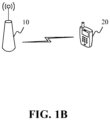
FIG. 1B is a scenario diagram illustrating a method of requesting system information according to an embodiment. -
FIG. 2 is a flowchart illustrating another method of requesting system information according to an embodiment. -
FIG. 3 is a flowchart illustrating a method of requesting system information according to an embodiment. -
FIG. 4 is a flowchart illustrating another method of sending system information according to an embodiment. -
FIG. 5 is a flowchart illustrating another method of sending system information according to an embodiment. -
FIG. 6 is a block diagram illustrating an apparatus for receiving system information according to an embodiment. -
FIG. 7 is a block diagram illustrating another apparatus for receiving system information according to an embodiment. -
FIG. 8 is a block diagram illustrating an apparatus for sending system information according to an embodiment. -
FIG. 9 is a block diagram illustrating another apparatus for sending system information according to an embodiment. -
FIG. 10 is a schematic diagram illustrating an apparatus adapted for requesting system information not being part of the present invention. -
FIG. 11 is a schematic diagram illustrating an apparatus adapted for requesting system information not being part of the present invention. - Embodiments will be described in detail here with the examples thereof illustrated in the drawings. Where the following descriptions involve the drawings, the same numerals in different drawings refer to the same or similar elements unless otherwise indicated. The implementation manners described in the following exemplary embodiments do not represent all implementation manners consistent with the present disclosure. Rather, they are merely examples of apparatuses and methods consistent with some aspects of the present disclosure whose scope is defined in the appended claims.
-
FIG. 1A is a flowchart illustrating a method of receiving system information according to an embodiment, andFIG. 1B is a scenario diagram illustrating a method of requesting system information according to an embodiment. The method of receiving system information is applied to UE. As shown inFIG. 1A , the method of requesting system information includes the following steps 110-130. - At
step 110, a first random access request is sent, where the first random access request carries at least one pilot code for identifying to-be-requested system information. - In an embodiment, the first random access request is a first message MSG 1 in the random access process.
- In an embodiment, a time-frequency resource of random access request may be obtained through a first type of system information broadcast by a base station, for example, the time-frequency resource of random access request is obtained through configuration information of a Physical Random Access Channel (PRACH) in a System Information Block 2 (SIB 2). The time-frequency resource of random access request may be determined through the related art.
- In an embodiment, the to-be-requested system information belongs to a second type of system information, such as, System Information Block 12 (SIB 12).
- In an embodiment, the pilot code of the to-be-requested system information is used to identify the to-be-requested system information, and the pilot code may be a preamble or an orthogonal code in other forms, which is not limited herein.
- In an embodiment, one or more pilot codes are carried in the first random access request.
- At
step 120, a response message corresponding to the first random access request is monitored within a preset time period, where the response message carries information for responding to the pilot code. - In an embodiment, the preset time period may be a negotiated time length between the base station and the user equipment. The response message is returned within the preset time period after the MSG 1 is sent. If the user equipment receives the response message within the preset time period, it may be considered that no more response message will be received.
- At
step 130, when the response message is detected, based on a pilot code identifier included in the response message, the to-be-requested system information is monitored and received within a transmission window of to-be-requested system information corresponding to the pilot code identifier. - In an embodiment, to-be-requested system information successfully requested is determined based on the pilot code identifier contained in the response message. For example, if the first random access request carries pilot code 1 corresponding to to-be-requested system information 1, pilot code 2 corresponding to to-be-requested system information 2, pilot code 3 corresponding to to-be-requested system information 3, and the response message corresponding to the first random access request only includes the pilot code identifiers corresponding to the pilot code 1 and the pilot code 2, it is determined that the to-be-requested system information successfully requested is the to-be-requested system information 1 and the to-be-requested system information 2.
- In an embodiment, the response message corresponding to the first random access request is a Random Access Response (RAR) message.
- In an embodiment, the UE may determine the transmission window of each piece of the to-be-requested system information through scheduling information carried in the first type of system information broadcast by the base station.
- In an exemplary scenario, as shown in
FIG. 1B , take the mobile network being the LTE network and the base station being an evolved node B (eNB) as an example for illustration. In the scenario shown inFIG. 1B , eNB 10 andUE 20 are included, where eNB 10 periodically broadcasts the first type of system information, andUE 20 may determine a time-domain resource of random access request, a transmission window of to-be-requested system information, and a pilot code of to-be-requested system information when receiving the first type of system information.UE 20 sends a first random access request carrying the pilot code of the to-be-requested system information on the time-domain resource of random access request. If the to-be-requested system information is determined to be successfully requested based on a response message responding to the first random access request, theUE 20 monitors the to-be-requested system information within the transmission window of to-be-requested system information successfully requested. If determining the to-be-requested system information is unsuccessfully requested based on the response message responding to the first random access request, theUE 20 may continue to send a second random access request on the time-domain resource of random access request until the to-be-requested system information is successfully requested or the time-domain resource is exhausted. - In the embodiment, through the
above steps 110 to 130, when the UE sends the random access request carrying the pilot code of the to-be-requested system information to the base station, through the above technical solutions, the UE is controlled to monitor the to-be-requested system information within the transmission window of to-be-requested system information successfully requested when the to-be-requested system information is successfully requested, so as to improve efficiency of sending and receiving the system information between the base station and the user equipment, thereby avoiding long latency for the user equipment to obtain the system information, reducing the power consumption for the base station to send the system information, and increasing the utilization rate of the spectrum resources. - In an embodiment, the method of requesting system information may further include:
receiving the to-be-requested system information within the transmission window of to-be-requested system information in response to determining that at least one part of the to-be-requested system information unsuccessfully requested is null. - In an embodiment, the method of requesting system information may further include:
- counting a number of requests for the to-be-requested system information; and
- when the number of requests is greater than a preset threshold, sending a network problem report message to a Radio Resource Control Layer, where the network problem report message is used for indicating the to-be-requested system information which exceeds the preset threshold of the random access request.
- In an embodiment, determining the at least one part of the to-be-requested system information unsuccessfully requested based on the monitoring result within the preset time period includes:
- in response to determining that no response message corresponding to the random access request is received within the preset time period, determining that the at least one part of the to-be-requested system information unsuccessfully requested is all of the to-be-requested system information; and
- in response to determining that the response message corresponding to the random access request is received within the preset time period, determining that the at least one part of the to-be-requested system information unsuccessfully requested is a part of the to-be-requested system information, where the part of the to-be-requested system information is not responded by information which is carried in the response message and used for responding to the pilot code.
- In particular, regarding how to request the system information, please refer to the following examples.
- Therefore, the above methods provided by the embodiments of the present disclosure improves the efficiency of sending and receiving the system information between the base station and the user equipment, thereby avoiding long latency for the user equipment to obtain the system information, reducing the power consumption for the base station to send the system information, and increasing the utilization rate of the spectrum resources.
- The technical solutions provided by the examples of the present disclosure are described in the following specific examples.
-
FIG. 2 is a flowchart illustrating another method of requesting system information according to an embodiment. In this embodiment, by using the above methods provided in the examples of the present disclosure, an example in which the UE requests the to-be-requested system information through the random access request is exemplary illustrated. As shown inFIG. 2 , the method includes the following steps. - At
step 210, a time-frequency resource of random access request is determined. - At
step 220, a first random access request is sent through the time-frequency resource of random access request, where the first random access request carries a pilot code of to-be-requested system information. - At
step 230, whether there is a response message corresponding to the first random access request is monitored within a preset time period. - At
step 240, when the response message is detected, based on a pilot code identifier carried in the response message, to-be-requested system information successfully requested and to-be-requested system information unsuccessfully requested are determined, and then step 250 and step 260 are performed. - In an embodiment, the monitoring result may be that no response massage is detected, and if so, at least one part of the to-be-requested system information unsuccessfully requested is all of the to-be-requested system information.
- In an embodiment, the monitoring result is that the response message is detected, the at least one part of the to-be-requested system information unsuccessfully-requested is a part of the to-be-requested system information, where the part of the to-be-requested system information is responded by information which is carried in the response message and used for responding to the pilot code. If the response message carries the information of the pilot code for responding to all of the to-be-requested system information, the value of the at least one part of the to-be-requested system information unsuccessfully requested is null. If the response message carries the information of the pilot code for responding to a part of the to-be-requested system information, the value of the at least one part of the to-be-requested system information unsuccessfully requested is not null.
- At
step 250, if the to-be-requested system information is successfully requested, the to-be-requested system information is monitored and received within a transmission window of to-be-requested system information successfully requested, and then the process ends. - At
step 260, if the to-be-requested system information is unsuccessfully requested, a second random access request is sent, where the second random access request carries a pilot code for identifying the to-be-requested system information unsuccessfully requested. - In an embodiment, each piece of to-be-requested system information may correspond to multiple pilot codes, e.g., to-be-requested system information 1 may correspond to pilot code 11, pilot code 12, or pilot code 13.
- In an embodiment, the pilot code of the to-be-requested system information unsuccessfully requested, which is carried in the second random access request, may be inconsistent with or consistent with the pilot code carried in the first random access request and corresponding to the to-be-requested system information. For example, when the to-be-requested system information 1 is unsuccessfully requested, if the pilot code of the to-be requested system information 1, which is carried in the first random access request, is the pilot code 11, the pilot code of the to-be-requested system information 1, which is carried in the second random access request may be the pilot code 12 or the pilot code 11.
- In an embodiment, the UE may determine whether there is any to-be-requested system information unsuccessfully requested, which is requested by the second random access request, based on the response message responding to the second random access request, and the process is the same as the process of determining the part of the to-be-requested system information unsuccessfully requested, which is requested by the first random access request, based on the response message responding to the first random access request.
- In an embodiment, if there is to-be-requested system information unsuccessfully requested after the UE sends the second random access request, the UE may continuously send the second random access request, until all of the to-be-requested system information is successfully requested or the time-domain resource of random access request is exhausted, where the pilot code carried in the second random access request sent later is the pilot code of the to-be-requested system information unsuccessfully requested.
- At
step 270, a number of requests for each piece of the to-be-requested system information is counted. - At
step 280, when the number of requests for a piece of the to-be-requested system information is greater than a preset threshold, it is indicated to a Radio Resource Control layer that the number of requests for the piece of the to-be-requested system information has reached a maximum threshold and the piece of the to-be-requested system information that has reached the maximum threshold. - In an embodiment, the preset threshold of requests may be a system default value, such as 3 times.
- In the embodiment, when determining that the request result of the to-be-requested system information is unsuccessfully requested, the UE may be controlled to repeatedly request the to-be-requested system information through the random access request until successfully requested, so as to improve the efficiency of sending and receiving the system information between the base station and the user equipment, thereby avoiding the long latency for the user equipment to obtain the system information, reducing power consumption for the base station to send the system information, and increasing the utilization rate of spectrum resources.
-
FIG. 3 is a flowchart illustrating a method of sending system information according to an embodiment. The method of requesting system information is applied to eNB, and the embodiment is illustrated in combination withFIG. 1B . As shown inFIG. 3 , the method of requesting system information includes the following steps 310-330. - At
step 310, a random access request carrying a pilot code of to-be-requested system information sent by user equipment is received. - At
step 320, a response message with a preset format is generated based on a request message. - In an embodiment, the preset format is a format that only includes one or more sub-packet headers, but does not include a packet body and thereby consists of the one or more sub-packet headers. For example, the preset format does not include information such as Cell Radio Network Temporary Identifier (C-RNTI) of the UE. A pilot code identifier carried in the response message is carried by the sub-packet header. The method of generating the response massage in this preset format refers to an example shown in
FIG. 4 . - In an embodiment, the preset format may be a format with a packet header and a packet body, where the packet header includes indicative information for indicating a number of the pilot codes in the packet body or indicating a length of the packet body. In an embodiment, the packet header may further include type indicative information for indicating a structure of the response message. The packet body may include one or more pilot code identifiers. The method of generating the response message in this preset format refers to an example shown in
FIG. 5 . - At
step 330, the response message is sent. - In an exemplary scenario, as shown in
FIG. 1B , take the mobile network being the LTE network and the base station being an evolved node B (eNB) as an example for illustration. In the scenario shown inFIG, 1B , eNB 10 andUE 20 are included, where the eNB 10 periodically broadcasts the first type of system information, and theUE 20 may determine a time-domain resource of random access request, a transmission window of to-be-requested system information, and a pilot code of to-be-requested system information when receiving the first type of system information. TheUE 20 sends a first random access request carrying the pilot code of the to-be-requested system information on the time-domain resource of random access request. If determining the to-be-requested system information is successfully requested based on a response message associated with the first random access request, theUE 20 monitors the to-be-requested system information within the transmission window of to-be-requested system information that is successfully requested. If determining the to-be-requested system information is unsuccessfully requested based on the response message associated with the first random access request, theUE 20 may continue to send a second random access request on the time-domain resource of random access request until the to-be-requested system information is successfully requested or the time-domain resource is exhausted. - In the embodiment, through the above steps 310-330, when receiving a request message sent by UE through a time-frequency resource of random access request, the base station generates the response message with the preset format to indicate whether the UE sends the to-be-requested system information within the transmission window of to-be-requested system information, so as to improve the efficiency of sending and receiving the system information between the base station and the UE.
- In an embodiment, generating the response message with the preset format based on the request message includes:
- analyzing the pilot code of the to-be-requested system information from the request message; and
- obtaining the response message with the preset format by adding a pilot code identifier of the pilot code of the to-be-requested system information which is determined for response, to a sub-packet header of the response message.
- In an embodiment, generating the response message with the preset format based on the request message includes:
- analyzing the pilot code of the to-be-requested system information from the request message; and
- obtaining the response message with the preset format by setting the number of pilot codes of the to-be-requested system information for response, or a length of a packet body of the response message in a packet header of the response message, and adding the pilot code identifier of the pilot code of the to-be-requested system information for response, to the packet body of the response message.
- In an embodiment, the packet header of the response message further includes indicative information for indicating a structure type of the response message.
- In an embodiment, the method of requesting system information further includes:
sending the to-be-requested system information for response, within the transmission window of to-be-requested system information. - In particular, regarding how to send the system information, please refer to the following examples.
- The technical solutions provided by the examples of the present disclosure are described in the following specific examples.
-
FIG. 4 is a flowchart illustrating another method of sending system information according to an embodiment. The example uses the above methods provided by the examples of the present disclosure to illustrate how to generate a response message with a preset format. As shown inFIG. 4 , the method includes the following steps. - At
step 410, a request message carrying a pilot code of to-be-requested system information sent by user equipment on a time-frequency resource of random access request is received. - At
step 420, the pilot code of the to-be-requested system information from the request massage is analyzed. - At
step 430, a response message with a preset format is obtained by adding a pilot code identifier of the pilot code of the to-be-requested system information which is determined for response, to a sub-packet header of the response message. - In an embodiment, the base station determines the to-be-requested system information for response currently, and determine the pilot code identifier of the pilot code of the to-be-requested system information for response. In an embodiment, a pilot code identifier may be added to each sub-packet header; and in another embodiment, multiple pilot code identifiers can be added to one sub-packet header.
- In an embodiment, since the preset format does not include a packet body, after determining the sub-packet header of the response message based on the pilot code of the to-be-requested system information, the response message with the preset format is obtained.
- At
step 440, the response message is sent, and the to-be-requested system information is sent within a transmission window of to-be-requested system information. - In an embodiment, the base station may send the to-be-requested system information for response more than once within the transmission window of to-be-requested system information.
- In the embodiment, the base station generates the response message according to the preset format to implement the request of the to-be-requested system information, so as to improve the efficiency of sending and receiving the system information between the base station and the user equipment.
-
FIG. 5 is a flowchart illustrating another method of sending system information according to an embodiment. The example uses the above methods provided by the examples of the present disclosure to illustrate how to generate a response message with a preset format. As shown inFIG. 5 , the method includes the following steps. - At
step 510, a request message carrying a pilot code of to-be-requested system information sent by user equipment on a time-frequency resource of random access request is received. - At
step 520, the pilot code of the to-be-requested system information is analyzed from the request message. - At
step 530, a response message with a preset format is obtained by setting a number of pilot codes of the to-be-requested system information for response or a length of a packet body of the response message in a packet header of the response message, and adding a pilot code identifier of the pilot code of the to-be-requested system information for response to the packet body of the response message. - In an embodiment, the base station may determine the to-be-requested system information for response currently, and determine the number of pilot codes of the to-be-requested system information for response, or a length of the packet body of the response message.
- In an embodiment, the packet header of the response message further includes indicative information for indicating a structure type of the response message.
- At
step 540, the response message is sent, and the to-be-requested system information is sent within a transmission window of to-be-requested system information. - In the embodiment, the base station may generate the response message according to the preset format to implement the request of the to-be-requested system information, so as to improve the efficiency of sending and receiving the system information between the base station and the user equipment.
-
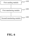
FIG. 6 is a block diagram illustrating an apparatus for requesting system information according to an embodiment. As shown inFIG. 6 , the apparatus for requesting system information includes: - a
first sending module 610, configured to send a first random access request, where the first random access request carries at least one pilot code for identifying to-be-requested system information; - a
first monitoring module 620, configured to monitor a response message corresponding to the first random access request within a preset time period, where the response message carries information for responding to the at least one pilot code; and - a
second monitoring module 630, configured to, when the response message is detected, based on a pilot code identifier included in the response message, monitor and receive the to-be-requested system information within a transmission window of to-be-requested system information corresponding to the pilot code identifier. -
FIG. 7 is a block diagram illustrating another apparatus for requesting system information according to an embodiment. As shown inFIG. 7 , on the basis of the embodiment shown inFIG. 6 , the apparatus further includes: - a first determining
module 640, configured to determine to-be-requested system information unsuccessfully requested based on the pilot code identifier included in the response message and the at least one pilot code carried in the first random access request for identifying the to-be-requested system information; and - a
second sending module 650, configured to send a second random access request, where the second random access request carries a pilot code of the to-be-requested system information that is unsuccessfully requested. - In an embodiment, the apparatus further includes:
- a
statistics module 660, configured to count a number of requests for each piece of the to-be-requested system information; and - a
problem reporting module 670, configured to indicate to a Radio Resource Control (RRC) layer that the number of requests for a piece of the to-be-requested system information has reached a maximum threshold, when the number of requests for the piece of the to-be-requested system information is greater than a preset threshold. - In an embodiment, the apparatus further includes:
a second determiningmodule 680, configured to determine that none of the to-be-requested system information is successfully requested when no response message is detected. -
FIG. 8 is a block diagram illustrating an apparatus for sending system information according to an embodiment. The apparatus is applied to a base station. As shown inFIG. 8 , the apparatus for sending system information includes: - a
first receiving module 810, configured to receive a random access request carrying a pilot code of to-be-requested system information sent by user equipment; - a
message generating module 820, configured to generate a response message with a preset format based on a request message received by thefirst receiving module 810; and - a
third sending module 830, configured to send the response message generated by themessage generating module 820. -
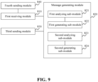
FIG. 9 is a block diagram illustrating another apparatus for sending system information according to an embodiment. As shown inFIG. 9 , on the basis of the embodiment shown inFIG. 8 , in an example, themessage generating module 820 includes: - a first analyzing
sub-module 821, configured to analyze the pilot code of the to-be-requested system information from the request message; and - a
first generating sub-module 822, configured to obtain the response message with the preset format by adding a pilot code identifier of the pilot code of the to-be-requested system information which is determined for response, to a sub-packet header of the response message. - In an embodiment, the
message generating module 820 includes: - a
second analyzing sub-module 823, configured to analyze the pilot code of the to-be-requested system information from the request message; and - a
second generating sub-module 824, configured to obtain the response message with the preset format by setting a number of pilot codes of the to-be-requested system information for response or a length of a packet body of the response message in a packet header of the response message, and adding a pilot code identifier of the pilot code of the to-be-requested system information for response to the packet body of the response message. - In an embodiment, the packet header of the response message further includes indicative information for indicating a structure type of the response message.
- In an embodiment, the apparatus further includes:
afourth sending module 840, configured to send the to-be-requested system information for response within a transmission window of to-be-requested system information. - Regarding the apparatuses illustrated in the above embodiments, the specific manner in which the respective modules perform operations has been described in detail in the method embodiments, which will not be repeated here.
-
FIG. 10 is a schematic diagram illustrating an apparatus for requesting system information. For example,apparatus 1000 may be a mobile telephone, a computer, a digital broadcasting terminal, a message receiving and transmitting device, a game console, a tablet device, a medical device, a fitness device, a personal digital assistant, and so on. - Referring to
FIG. 10 , theapparatus 1000 may include one or more of the following components: aprocessing component 1002, amemory 1004, apower supply component 1006, amultimedia component 1008, anaudio component 1010, an input/output (I/O)interface 1012, asensor component 1014 and acommunication component 1013. - The
processing component 1002 generally controls overall operations of theapparatus 1000, such as operations associated with display, phone calls, data communications, camera operations, and recording operations. Theprocessing component 1002 may include one ormore processors 1020 to execute instructions to complete all or part of the steps of the above methods. In addition, theprocessing component 1002 may include one or more modules which facilitate the interaction between theprocessing component 1002 and other components. For example, theprocessing component 1002 may include a multimedia module to facilitate the interaction between themultimedia component 1008 and theprocessing component 1002. - The
memory 1004 is to store various types of data to support the operation of theapparatus 1000. Examples of such data include instructions for any application or method operated on theapparatus 1000, contact data, phonebook data, messages, pictures, videos, and so on. Thememory 1004 may be implemented by any type of volatile or non-volatile storage devices or a combination thereof, such as a Static Random Access Memory (SRAM), an Electrically Erasable Programmable Read-Only Memory (EEPROM), an Erasable Programmable Read-Only Memory (EPROM), a Programmable Read-Only Memory (PROM), a Read-Only Memory (ROM), a magnetic memory, a flash memory, a magnetic or optical disk. - The
power supply component 1006 provides power to different components of theapparatus 1000. Thepower supply component 1006 may include a power management system, one or more power supplies, and other components associated with generating, managing, and distributing power for theapparatus 1000. - The
multimedia component 1008 includes a screen providing an output interface between theapparatus 1000 and a user. In some embodiments, the screen may include a Liquid Crystal Display (LCD) and a Touch Panel (TP). If the screen includes the TP, the screen may be implemented as a touch screen to receive input signals from the user. The TP may include one or more touch sensors to sense touches, swipes, and gestures on the TP. The touch sensors may not only sense a boundary of a touch or swipe, but also sense a duration and a pressure associated with the touch or swipe. In some embodiments, themultimedia component 1008 may include a front camera and/or a rear camera. The front camera and/or rear camera may receive external multimedia data when theapparatus 1000 is in an operating mode, such as a photographing mode or a video mode. Each of the front camera and the rear camera may be a fixed optical lens system or have focal length and optical zooming capability. - The
audio component 1010 is to output and/or input an audio signal. For example, theaudio component 1010 includes a microphone (MIC). When theapparatus 1000 is in an operating mode, such as a call mode, a recording mode, and a voice recognition mode, the MIC is to receive an external audio signal. The received audio signal may be further stored in thememory 1004 or sent via thecommunication component 1013. In some embodiments, theaudio component 1010 further includes a speaker to output an audio signal. - The I/
O interface 1012 may provide an interface between theprocessing component 1002 and peripheral interface modules. The above peripheral interface modules may include a keyboard, a click wheel, buttons and so on. These buttons may include, but are not limited to, a home button, a volume button, a starting button and a locking button. - The
sensor component 1014 includes one or more sensors to provide status assessments of various aspects for theapparatus 1000. For example, thesensor component 1014 may detect the on/off status of theapparatus 1000, and relative positioning of component, for example, the component is a display and a keypad of theapparatus 1000. Thesensor component 1014 may also detect a change in position of theapparatus 1000 or a component of theapparatus 1000, a presence or absence of the contact between a user and theapparatus 1000, an orientation or an acceleration/deceleration of theapparatus 1000, and a change in temperature of theapparatus 1000. Thesensor component 1014 may include a proximity sensor to detect the presence of a nearby object without any physical contact. Thesensor component 1014 may further include an optical sensor, such as a Complementary Metal-Oxide-Semiconductor (CMOS) or Charged Coupled Device (CCD) image sensor which is used in imaging applications. In some embodiments, thesensor component 1014 may further include an acceleration sensor, a gyroscope sensor, a magnetic sensor, a pressure sensor, or a temperature sensor. - The
communication component 1013 is to facilitate wired or wireless communication between theapparatus 1000 and other devices. Theapparatus 1000 may access a wireless network that is based on a communication standard, such as Wi-Fi, 2G or 3G, or a combination thereof. In an embodiment, thecommunication component 1013 receives a broadcast signal or broadcast-associated information from an external broadcast management system via a broadcast channel. In an embodiment, thecommunication component 1013 further includes a Near Field Communication (NFC) module to facilitate short-range communications. For example, the NFC module may be implemented based on a Radio Frequency Identification (RFID) technology, an Infrared Data Association (IrDA) technology, an Ultra Wideband (UWB) technology, a Bluetooth® (BT) technology and other technologies. - In an embodiment, the
apparatus 1000 may be implemented by one or more Application Specific Integrated Circuits (ASICs), Digital Signal Processors (DSPs), Digital Signal Processing Devices (DSPDs), programmable Logic Devices (PLDs), Field Programmable Gate Arrays (FPGAs), controllers, microcontrollers, microprocessors, or other electronic components for performing the above methods. - In an aspect not being part of the present invention, there is also provided a non-transitory computer-readable storage medium including instructions, such as the
memory 1004 including instructions. The instructions may be executed by theprocessor 1020 of theapparatus 1000 to perform the above described methods, including the following steps: - sending a first random access request, where the first random access request carries at least one pilot code for identifying to-be-requested system information;
- monitoring a response message corresponding to the first random access request within a preset time period, where the response message carries information for responding to the pilot code; and
- when the response message is detected, based on a pilot code identifier included in the response message, monitoring and receiving the to-be-requested system information within a transmission window of to-be-requested system information corresponding to the pilot code identifier.
-
FIG. 11 is a schematic diagram illustrating an apparatus adapted for sending system information. Theapparatus 1100 may be provided as a base station. Referring toFIG. 11 , theapparatus 1100 includes aprocessing component 1122, a wireless transmitting/receiving component 1124, anantenna component 1126 and a signal processing component specific to a wireless interface. Theprocessing component 1122 may further include one or more processors. - One of the processors in the
processing component 1122 may be configured to: - receive a random access request carrying a pilot code of the to-be-requested system information sent by user equipment;
- generate a response message with a preset format based on a request message; and
- send the response message.
- In an aspect not being part of the present invention, a non-transitory computer-readable storage medium including instructions is also provided in the base station. The non-transitory computer-readable storage medium stores instructions that, when the instructions are executed by a processor to implement the following steps including:
- receiving a random access request carrying a pilot code of the to-be-requested system information sent by user equipment;
- generating a response message with a preset format based on the random access request; and
- sending the response message.
- It is to be understood that the present disclosure is not limited to the precise structure described above and shown in the accompanying drawings, and that various modifications and changes may be made without departing from the scope thereof. The scope of the present disclosure is limited only by the appended claims.
Claims (11)
- A method of requesting system information implemented by a User Equipment, UE (20), comprising:sending a first random access request to a base station, wherein the first random access request carries at least one pilot code for identifying to-be-requested system information;monitoring a response message corresponding to the first random access request within a preset time period, wherein the response message comprises a pilot code identifier of the pilot code of the to-be-requested system information which is determined by the base station for response;characterized in that the method further comprises:determining by the UE whether the to-be-requested system information is successfully requested based on whether the pilot code identifier contained in the response message corresponds to the pilot code carried in the random access request; andif the to-be-requested system information is determined to be successfully requested, monitoring and receiving the to-be-requested system information within a transmission window of to-be-requested system information corresponding to the pilot code identifier;wherein the response message has a format that consists of one or more sub-packet headers, and the pilot code identifier is carried by a sub-packet header of the response message.
- The method according to claim 1, further comprising:
if the to-be-requested system information is determined to be unsuccessfully requested, sending a second random access request, wherein the second random access request carries a pilot code of the to-be-requested system information that is unsuccessfully requested. - The method according to claim 2, further comprising:counting a number of requests for each piece of the to-be-requested system information; andwhen the number of requests for a piece of the to-be-requested system information is greater than a preset threshold, indicating to a Radio Resource Control layer that the number of requests for the piece of to-be-requested system information has reached a maximum threshold.
- The method according to claim 1, further comprising:
when no response message is detected, determining that none of the to-be-requested system information is successfully requested. - A method of sending system information implemented by a base station, comprising:receiving a random access request sent by a User Equipment, UE (20), wherein the random access request carries a pilot code of to-be-requested system information;characterized in that the method further comprises:generating a response message with a preset format based on therequest message, wherein the response message comprises a pilot code identifier of the pilot code of the to-be-requested system information which is determined for response, the response message has the preset format that consists of one or more sub-packet headers, and the pilot code identifier is carried by a sub-packet header of the response message;sending the response message within a preset time period; andsending the to-be-requested system information for response within a transmission window of to-be-requested system information, such that the UE determines whether the to-be-requested system information is successfully requested based on whether the pilot code identifier contained in the response message corresponds to the pilot code carried in the random access request.
- The method according to claim 5, wherein generating the response message with the preset format based on the request message comprises:analyzing the pilot code of the to-be-requested system information from the request message; andobtaining the response message with the preset format by adding a pilot code identifier of a pilot code of the to-be-requested system information determined for response to the sub-packet header of the response message.
- A User Equipment, UE (20), for requesting system information, comprising:a first sending module, configured to send a first random access request to a base station, wherein the first random access request carries at least one pilot code for identifying to-be-requested system information;a first monitoring module, configured to monitor a response message corresponding to the first random access request within a preset time period, wherein the response message comprises a pilot code identifier of the pilot code of the to-be-requested system information which is determined by the base station for response;characterized in that the UE (20) further comprises:a second monitoring module, configured to, determine whether the to-be-requested system information is successfully requested based on whether the pilot code identifier contained in the response message corresponds to the pilot code carried in the random access request, and if the to-be-requested system information is determined to be successfully requested, monitor and receive the to-be-requested system information within a transmission window of to-be-requested system information corresponding to the pilot code identifier;wherein the response message has a format that consists of one or more sub-packet headers, and the pilot code identifier is carried by a sub-packet header of the response message.
- The UE according to claim 7, further comprising:
a second sending module, configured to send a second random access request if the to-be-requested system information is determined to be unsuccessfully requested, wherein the second random access request carries a pilot code of the to-be-requested system information that is unsuccessfully requested. - The UE according to claim 7, further comprising:a statistics module, configured to count a number of requests for each piece of the to-be-requested system information; anda problem reporting module, configured to instruct to a Radio Resource Control layer that the number of requests for the piece of to-be-requested system information has reached a maximum threshold when the number of requests for a piece of the to-be-requested system information is greater than a preset threshold.
- A base station, for sending system information, comprising:a first receiving module, configured to receive a random access request sent by a User Equipment, UE (20), wherein the random access request carries a pilot code of to-be-requested system information;characterized in that the base station further comprises:,a message generating module, configured to generate a response message with a preset format based on therequest message received by the first receiving module, wherein the response message comprises a pilot code identifier of the pilot code of the to to-be-requested system information which is determined for response, the response message has the preset format that consists of one or more sub-packet headers, and the pilot code identifier is carried by a sub-packet header of the response message;a third sending module, configured to send the response message generated by the message generating module within a preset time period; anda fourth sending module, configured to send the to-be-requested system information for response within a transmission window of to-be-requested system information, such that the UE determines whether the to-be-requested system information is successfully requested based on whether the pilot code identifier contained in the response message corresponds to the pilot code carried in the random access request.
- The base station according to claim 10, wherein the message generating module comprises:a first analyzing sub-module, configured to analyze the pilot code of the to-be-requested system information from the request message; anda first generating sub-module, configured to obtain the response message with the preset format by adding a pilot code identifier of a pilot code of the to-be-requested system information determined for response to the sub-packet header of the response message.
Priority Applications (1)
| Application Number | Priority Date | Filing Date | Title |
|---|---|---|---|
| EP23158485.5A EP4213426A1 (en) | 2017-04-17 | 2017-04-17 | Method, apparatus for requesting system information, user equipment and base station |
Applications Claiming Priority (1)
| Application Number | Priority Date | Filing Date | Title |
|---|---|---|---|
| PCT/CN2017/080713 WO2018191839A1 (en) | 2017-04-17 | 2017-04-17 | Method used to request system information, apparatus, user equipment and base station |
Related Child Applications (2)
| Application Number | Title | Priority Date | Filing Date |
|---|---|---|---|
| EP23158485.5A Division-Into EP4213426A1 (en) | 2017-04-17 | 2017-04-17 | Method, apparatus for requesting system information, user equipment and base station |
| EP23158485.5A Division EP4213426A1 (en) | 2017-04-17 | 2017-04-17 | Method, apparatus for requesting system information, user equipment and base station |
Publications (3)
| Publication Number | Publication Date |
|---|---|
| EP3614599A1 EP3614599A1 (en) | 2020-02-26 |
| EP3614599A4 EP3614599A4 (en) | 2020-04-22 |
| EP3614599B1 true EP3614599B1 (en) | 2023-04-12 |
Family
ID=59953952
Family Applications (2)
| Application Number | Title | Priority Date | Filing Date |
|---|---|---|---|
| EP23158485.5A Pending EP4213426A1 (en) | 2017-04-17 | 2017-04-17 | Method, apparatus for requesting system information, user equipment and base station |
| EP17906580.0A Active EP3614599B1 (en) | 2017-04-17 | 2017-04-17 | Method used to request system information, apparatus, user equipment and base station |
Family Applications Before (1)
| Application Number | Title | Priority Date | Filing Date |
|---|---|---|---|
| EP23158485.5A Pending EP4213426A1 (en) | 2017-04-17 | 2017-04-17 | Method, apparatus for requesting system information, user equipment and base station |
Country Status (11)
| Country | Link |
|---|---|
| US (3) | US11096223B2 (en) |
| EP (2) | EP4213426A1 (en) |
| JP (1) | JP6961795B2 (en) |
| KR (1) | KR102314479B1 (en) |
| CN (1) | CN107223353B (en) |
| BR (1) | BR112019021576A2 (en) |
| ES (1) | ES2945133T3 (en) |
| PL (1) | PL3614599T3 (en) |
| RU (1) | RU2726741C1 (en) |
| SG (1) | SG11201909607PA (en) |
| WO (1) | WO2018191839A1 (en) |
Families Citing this family (15)
| Publication number | Priority date | Publication date | Assignee | Title |
|---|---|---|---|---|
| US11419143B2 (en) * | 2017-06-08 | 2022-08-16 | Qualcomm Incorporated | Random access procedure in a wireless backhaul network |
| US11528749B2 (en) | 2017-06-08 | 2022-12-13 | Qualcomm Incorporated | Techniques and apparatuses for random access procedure in a wireless backhaul network |
| WO2019095292A1 (en) * | 2017-11-17 | 2019-05-23 | 北京小米移动软件有限公司 | System information configuration and reading method and apparatus, base station and user equipment |
| WO2019148495A1 (en) * | 2018-02-05 | 2019-08-08 | 北京小米移动软件有限公司 | System message receiving method and device, and system message transmitting method and device |
| US11317341B2 (en) | 2018-03-16 | 2022-04-26 | Beijing Xiaomi Mobile Software Co., Ltd. | System information request adjustment method and apparatus, and user equipment |
| WO2019183763A1 (en) * | 2018-03-26 | 2019-10-03 | 北京小米移动软件有限公司 | Information recording method and information recording device |
| AU2018415756A1 (en) | 2018-03-28 | 2020-09-10 | Guangdong Oppo Mobile Telecommunications Corp., Ltd. | Method for acquiring system information, and terminal device and network device |
| US10791502B2 (en) * | 2018-04-02 | 2020-09-29 | FG Innovation Company Limited | On-demand system information request procedure and error handling |
| CN110418419B (en) | 2018-04-28 | 2022-03-25 | 中国移动通信有限公司研究院 | Random access method, terminal and network equipment |
| WO2019213846A1 (en) * | 2018-05-08 | 2019-11-14 | Nokia Shanghai Bell Co., Ltd. | Monitoring of random access procedure |
| CN111869282B (en) * | 2018-10-30 | 2023-06-02 | Oppo广东移动通信有限公司 | Window configuration method and device, terminal and network equipment |
| WO2020087471A1 (en) * | 2018-11-01 | 2020-05-07 | 北京小米移动软件有限公司 | Method and apparatus for processing si request, terminal and storage medium |
| WO2020087476A1 (en) * | 2018-11-01 | 2020-05-07 | Oppo广东移动通信有限公司 | Method and device for transmitting system information |
| BR112021016050A2 (en) * | 2019-02-14 | 2021-10-05 | Beijing Xiaomi Mobile Software Co., Ltd. | METHOD AND APPARATUS FOR RANDOM ACCESS TO PROCESSING |
| EP4195785A4 (en) * | 2020-08-28 | 2023-10-11 | Huawei Technologies Co., Ltd. | Communication method and apparatus |
Family Cites Families (17)
| Publication number | Priority date | Publication date | Assignee | Title |
|---|---|---|---|---|
| CN101572594B (en) * | 2008-04-29 | 2013-01-16 | 中兴通讯股份有限公司 | Dispatching method of system messages |
| CN101784121B (en) * | 2009-01-20 | 2012-01-04 | 华为技术有限公司 | Random access method, device and system |
| CN101827450B (en) * | 2009-03-04 | 2012-07-04 | 华为技术有限公司 | Random access method, device and system |
| CN101695196B (en) * | 2009-10-20 | 2011-08-31 | 普天信息技术研究院有限公司 | Method for increasing random access success rate under competition mode, system and device thereof |
| WO2011084008A2 (en) * | 2010-01-07 | 2011-07-14 | 엘지전자 주식회사 | Method for performing deregistration with content retention mode in broadband wireless access system |
| KR20120070689A (en) * | 2010-12-22 | 2012-07-02 | 한국전자통신연구원 | Random access method for machine type communications and wireless communication apparatus using the method |
| GB2487908B (en) * | 2011-02-04 | 2015-06-17 | Sca Ipla Holdings Inc | Telecommunications method and system |
| GB2493702B (en) * | 2011-08-11 | 2016-05-04 | Sca Ipla Holdings Inc | OFDM subcarrier allocations in wireless telecommunications systems |
| JP5834639B2 (en) * | 2011-09-02 | 2015-12-24 | ソニー株式会社 | COMMUNICATION DEVICE, COMMUNICATION METHOD, COMMUNICATION SYSTEM, AND BASE STATION |
| WO2013168776A1 (en) * | 2012-05-11 | 2013-11-14 | 京セラ株式会社 | Communication control method, user terminal, processor, storage medium, and base station |
| CN103067880A (en) * | 2013-01-09 | 2013-04-24 | 中兴通讯股份有限公司 | Method of sending clustering messages, network side equipment and terminal equipment |
| WO2015005724A1 (en) * | 2013-07-12 | 2015-01-15 | 엘지전자 주식회사 | Communication method and wireless device for supporting variable bandwidth |
| EP3245835B1 (en) * | 2015-01-13 | 2019-06-05 | Telefonaktiebolaget LM Ericsson (publ) | A network node, a wireless device and respective method performed thereby for use in a random access procedure therebetween in a cell of the network node |
| KR102399944B1 (en) * | 2015-06-11 | 2022-05-18 | 애플 인크. | Low-overhead system information acquisition for wireless communication |
| ES2940073T3 (en) * | 2016-02-29 | 2023-05-03 | Samsung Electronics Co Ltd | Apparatus and procedure for signaling system information |
| SG11201811641VA (en) * | 2016-06-30 | 2019-01-30 | Beijing Xiaomi Mobile Software Co Ltd | Method and apparatus for transmitting system information |
| US10834759B2 (en) * | 2017-03-20 | 2020-11-10 | Motorola Mobility Llc | Feedback for a system information request |
-
2017
- 2017-04-17 ES ES17906580T patent/ES2945133T3/en active Active
- 2017-04-17 BR BR112019021576A patent/BR112019021576A2/en unknown
- 2017-04-17 WO PCT/CN2017/080713 patent/WO2018191839A1/en unknown
- 2017-04-17 CN CN201780000210.2A patent/CN107223353B/en active Active
- 2017-04-17 EP EP23158485.5A patent/EP4213426A1/en active Pending
- 2017-04-17 RU RU2019134995A patent/RU2726741C1/en active
- 2017-04-17 PL PL17906580.0T patent/PL3614599T3/en unknown
- 2017-04-17 KR KR1020197033977A patent/KR102314479B1/en active IP Right Grant
- 2017-04-17 SG SG11201909607P patent/SG11201909607PA/en unknown
- 2017-04-17 EP EP17906580.0A patent/EP3614599B1/en active Active
- 2017-04-17 JP JP2020505953A patent/JP6961795B2/en active Active
-
2019
- 2019-10-15 US US16/653,340 patent/US11096223B2/en active Active
-
2021
- 2021-07-06 US US17/368,175 patent/US11612000B2/en active Active
-
2023
- 2023-02-22 US US18/172,467 patent/US20230199858A1/en active Pending
Also Published As
| Publication number | Publication date |
|---|---|
| SG11201909607PA (en) | 2019-11-28 |
| US20230199858A1 (en) | 2023-06-22 |
| JP6961795B2 (en) | 2021-11-05 |
| US11612000B2 (en) | 2023-03-21 |
| WO2018191839A1 (en) | 2018-10-25 |
| PL3614599T3 (en) | 2023-08-14 |
| KR102314479B1 (en) | 2021-10-18 |
| CN107223353B (en) | 2018-09-04 |
| US20200045749A1 (en) | 2020-02-06 |
| JP2020517208A (en) | 2020-06-11 |
| US20210337600A1 (en) | 2021-10-28 |
| ES2945133T3 (en) | 2023-06-28 |
| BR112019021576A2 (en) | 2020-05-05 |
| EP3614599A1 (en) | 2020-02-26 |
| RU2726741C1 (en) | 2020-07-15 |
| CN107223353A (en) | 2017-09-29 |
| EP3614599A4 (en) | 2020-04-22 |
| KR20190136084A (en) | 2019-12-09 |
| US11096223B2 (en) | 2021-08-17 |
| EP4213426A1 (en) | 2023-07-19 |
Similar Documents
| Publication | Publication Date | Title |
|---|---|---|
| US11612000B2 (en) | Methods and apparatuses for requesting system information | |
| JP2023520478A (en) | Configuration information transmission method and device, communication device and storage medium | |
| CN106992953B (en) | System information acquisition method and device | |
| CN109451842B (en) | Power saving method and device for user equipment, user equipment and base station | |
| US11516832B2 (en) | Method and device for transmitting data in unlicensed cell, base station and user equipment | |
| CN110771222B (en) | Paging configuration method, device, communication equipment and storage medium | |
| US11956824B2 (en) | Methods and devices for access control, user equipment and base stations | |
| EP3541119B1 (en) | Method, apparatus, user equipment and base station for sending and receiving system information | |
| CN110495192B (en) | Random access method, device and storage medium | |
| CN110337830B (en) | Monitoring method, signaling issuing method and device, communication equipment and storage | |
| US20230180180A1 (en) | Paging processing methods, base station and user equipment | |
| CN114125977B (en) | Service switching method and device | |
| CN109156025B (en) | Uplink resource acquisition method, device and computer readable storage medium | |
| US10999002B2 (en) | Method and apparatus for determining modulation and coding scheme | |
| CN113115592B (en) | HARQ-ACK transmission method and device and communication equipment | |
| WO2023050350A1 (en) | Determination method and apparatus for cfr, and communication device and storage medium | |
| US20230262691A1 (en) | Uplink transmission sending method and apparatus, uplink transmission receiving method and apparatus, communication device, and medium | |
| CN109792750B (en) | Carrier configuration method and device | |
| EP4057551A1 (en) | Downlink control information configuration method and apparatus, and communication device and storage medium | |
| US20210392520A1 (en) | Network parameter configuration method and apparatus, and computer-readable storage medium | |
| CN112673692B (en) | Preconfigured resource control method, data transmission method, device and storage medium | |
| CN112673702B (en) | Random access method, device and storage medium | |
| CN115152291A (en) | Data transmission method, device and storage medium | |
| CN116724513A (en) | Information indication method, device, system, communication equipment and storage medium | |
| CN116671136A (en) | Method, device, communication equipment and storage medium for determining and monitoring MBS (multicast service) by using resources |
Legal Events
| Date | Code | Title | Description |
|---|---|---|---|
| STAA | Information on the status of an ep patent application or granted ep patent |
Free format text: STATUS: THE INTERNATIONAL PUBLICATION HAS BEEN MADE |
|
| PUAI | Public reference made under article 153(3) epc to a published international application that has entered the european phase |
Free format text: ORIGINAL CODE: 0009012 |
|
| STAA | Information on the status of an ep patent application or granted ep patent |
Free format text: STATUS: REQUEST FOR EXAMINATION WAS MADE |
|
| 17P | Request for examination filed |
Effective date: 20191105 |
|
| AK | Designated contracting states |
Kind code of ref document: A1 Designated state(s): AL AT BE BG CH CY CZ DE DK EE ES FI FR GB GR HR HU IE IS IT LI LT LU LV MC MK MT NL NO PL PT RO RS SE SI SK SM TR |
|
| AX | Request for extension of the european patent |
Extension state: BA ME |
|
| A4 | Supplementary search report drawn up and despatched |
Effective date: 20200325 |
|
| RIC1 | Information provided on ipc code assigned before grant |
Ipc: H04L 1/16 20060101AFI20200319BHEP Ipc: H04W 52/02 20090101ALI20200319BHEP Ipc: H04W 74/00 20090101ALI20200319BHEP Ipc: H04W 74/08 20090101ALI20200319BHEP |
|
| DAV | Request for validation of the european patent (deleted) | ||
| DAX | Request for extension of the european patent (deleted) | ||
| STAA | Information on the status of an ep patent application or granted ep patent |
Free format text: STATUS: EXAMINATION IS IN PROGRESS |
|
| STAA | Information on the status of an ep patent application or granted ep patent |
Free format text: STATUS: EXAMINATION IS IN PROGRESS |
|
| 17Q | First examination report despatched |
Effective date: 20211103 |
|
| REG | Reference to a national code |
Ref document number: 602017067747 Country of ref document: DE Ref country code: DE Ref legal event code: R079 Free format text: PREVIOUS MAIN CLASS: H04L0001160000 Ipc: H04W0048140000 |
|
| GRAP | Despatch of communication of intention to grant a patent |
Free format text: ORIGINAL CODE: EPIDOSNIGR1 |
|
| STAA | Information on the status of an ep patent application or granted ep patent |
Free format text: STATUS: GRANT OF PATENT IS INTENDED |
|
| RIC1 | Information provided on ipc code assigned before grant |
Ipc: H04W 74/08 20090101ALI20220425BHEP Ipc: H04W 52/02 20090101ALI20220425BHEP Ipc: H04W 48/14 20090101AFI20220425BHEP |
|
| INTG | Intention to grant announced |
Effective date: 20220511 |
|
| GRAJ | Information related to disapproval of communication of intention to grant by the applicant or resumption of examination proceedings by the epo deleted |
Free format text: ORIGINAL CODE: EPIDOSDIGR1 |
|
| STAA | Information on the status of an ep patent application or granted ep patent |
Free format text: STATUS: EXAMINATION IS IN PROGRESS |
|
| INTC | Intention to grant announced (deleted) | ||
| GRAP | Despatch of communication of intention to grant a patent |
Free format text: ORIGINAL CODE: EPIDOSNIGR1 |
|
| STAA | Information on the status of an ep patent application or granted ep patent |
Free format text: STATUS: GRANT OF PATENT IS INTENDED |
|
| INTG | Intention to grant announced |
Effective date: 20221018 |
|
| GRAS | Grant fee paid |
Free format text: ORIGINAL CODE: EPIDOSNIGR3 |
|
| GRAA | (expected) grant |
Free format text: ORIGINAL CODE: 0009210 |
|
| STAA | Information on the status of an ep patent application or granted ep patent |
Free format text: STATUS: THE PATENT HAS BEEN GRANTED |
|
| AK | Designated contracting states |
Kind code of ref document: B1 Designated state(s): AL AT BE BG CH CY CZ DE DK EE ES FI FR GB GR HR HU IE IS IT LI LT LU LV MC MK MT NL NO PL PT RO RS SE SI SK SM TR |
|
| REG | Reference to a national code |
Ref country code: GB Ref legal event code: FG4D |
|
| REG | Reference to a national code |
Ref country code: CH Ref legal event code: EP |
|
| REG | Reference to a national code |
Ref country code: DE Ref legal event code: R096 Ref document number: 602017067747 Country of ref document: DE |
|
| REG | Reference to a national code |
Ref country code: RO Ref legal event code: EPE |
|
| REG | Reference to a national code |
Ref country code: IE Ref legal event code: FG4D |
|
| REG | Reference to a national code |
Ref country code: AT Ref legal event code: REF Ref document number: 1560476 Country of ref document: AT Kind code of ref document: T Effective date: 20230515 |
|
| REG | Reference to a national code |
Ref country code: NL Ref legal event code: FP |
|
| P01 | Opt-out of the competence of the unified patent court (upc) registered |
Effective date: 20230523 |
|
| REG | Reference to a national code |
Ref country code: ES Ref legal event code: FG2A Ref document number: 2945133 Country of ref document: ES Kind code of ref document: T3 Effective date: 20230628 |
|
| PGFP | Annual fee paid to national office [announced via postgrant information from national office to epo] |
Ref country code: RO Payment date: 20230629 Year of fee payment: 7 Ref country code: NL Payment date: 20230519 Year of fee payment: 7 Ref country code: FR Payment date: 20230606 Year of fee payment: 7 Ref country code: ES Payment date: 20230627 Year of fee payment: 7 Ref country code: DE Payment date: 20230519 Year of fee payment: 7 |
|
| REG | Reference to a national code |
Ref country code: LT Ref legal event code: MG9D |
|
| REG | Reference to a national code |
Ref country code: AT Ref legal event code: MK05 Ref document number: 1560476 Country of ref document: AT Kind code of ref document: T Effective date: 20230412 |
|
| PG25 | Lapsed in a contracting state [announced via postgrant information from national office to epo] |
Ref country code: SE Free format text: LAPSE BECAUSE OF FAILURE TO SUBMIT A TRANSLATION OF THE DESCRIPTION OR TO PAY THE FEE WITHIN THE PRESCRIBED TIME-LIMIT Effective date: 20230412 Ref country code: PT Free format text: LAPSE BECAUSE OF FAILURE TO SUBMIT A TRANSLATION OF THE DESCRIPTION OR TO PAY THE FEE WITHIN THE PRESCRIBED TIME-LIMIT Effective date: 20230814 Ref country code: NO Free format text: LAPSE BECAUSE OF FAILURE TO SUBMIT A TRANSLATION OF THE DESCRIPTION OR TO PAY THE FEE WITHIN THE PRESCRIBED TIME-LIMIT Effective date: 20230712 Ref country code: AT Free format text: LAPSE BECAUSE OF FAILURE TO SUBMIT A TRANSLATION OF THE DESCRIPTION OR TO PAY THE FEE WITHIN THE PRESCRIBED TIME-LIMIT Effective date: 20230412 |
|
| PGFP | Annual fee paid to national office [announced via postgrant information from national office to epo] |
Ref country code: IT Payment date: 20230731 Year of fee payment: 7 Ref country code: GB Payment date: 20230524 Year of fee payment: 7 |
|
| PG25 | Lapsed in a contracting state [announced via postgrant information from national office to epo] |
Ref country code: RS Free format text: LAPSE BECAUSE OF FAILURE TO SUBMIT A TRANSLATION OF THE DESCRIPTION OR TO PAY THE FEE WITHIN THE PRESCRIBED TIME-LIMIT Effective date: 20230412 Ref country code: LV Free format text: LAPSE BECAUSE OF FAILURE TO SUBMIT A TRANSLATION OF THE DESCRIPTION OR TO PAY THE FEE WITHIN THE PRESCRIBED TIME-LIMIT Effective date: 20230412 Ref country code: LT Free format text: LAPSE BECAUSE OF FAILURE TO SUBMIT A TRANSLATION OF THE DESCRIPTION OR TO PAY THE FEE WITHIN THE PRESCRIBED TIME-LIMIT Effective date: 20230412 Ref country code: IS Free format text: LAPSE BECAUSE OF FAILURE TO SUBMIT A TRANSLATION OF THE DESCRIPTION OR TO PAY THE FEE WITHIN THE PRESCRIBED TIME-LIMIT Effective date: 20230812 Ref country code: HR Free format text: LAPSE BECAUSE OF FAILURE TO SUBMIT A TRANSLATION OF THE DESCRIPTION OR TO PAY THE FEE WITHIN THE PRESCRIBED TIME-LIMIT Effective date: 20230412 Ref country code: GR Free format text: LAPSE BECAUSE OF FAILURE TO SUBMIT A TRANSLATION OF THE DESCRIPTION OR TO PAY THE FEE WITHIN THE PRESCRIBED TIME-LIMIT Effective date: 20230713 |
|
| PGFP | Annual fee paid to national office [announced via postgrant information from national office to epo] |
Ref country code: PL Payment date: 20230601 Year of fee payment: 7 |
|
| REG | Reference to a national code |
Ref country code: CH Ref legal event code: PL |
|
| PG25 | Lapsed in a contracting state [announced via postgrant information from national office to epo] |
Ref country code: LU Free format text: LAPSE BECAUSE OF NON-PAYMENT OF DUE FEES Effective date: 20230417 Ref country code: FI Free format text: LAPSE BECAUSE OF FAILURE TO SUBMIT A TRANSLATION OF THE DESCRIPTION OR TO PAY THE FEE WITHIN THE PRESCRIBED TIME-LIMIT Effective date: 20230412 |
|
| REG | Reference to a national code |
Ref country code: BE Ref legal event code: MM Effective date: 20230430 |
|
| REG | Reference to a national code |
Ref country code: DE Ref legal event code: R097 Ref document number: 602017067747 Country of ref document: DE |
|
| PG25 | Lapsed in a contracting state [announced via postgrant information from national office to epo] |
Ref country code: SK Free format text: LAPSE BECAUSE OF FAILURE TO SUBMIT A TRANSLATION OF THE DESCRIPTION OR TO PAY THE FEE WITHIN THE PRESCRIBED TIME-LIMIT Effective date: 20230412 |
|
| PG25 | Lapsed in a contracting state [announced via postgrant information from national office to epo] |
Ref country code: MC Free format text: LAPSE BECAUSE OF FAILURE TO SUBMIT A TRANSLATION OF THE DESCRIPTION OR TO PAY THE FEE WITHIN THE PRESCRIBED TIME-LIMIT Effective date: 20230412 |
|
| PG25 | Lapsed in a contracting state [announced via postgrant information from national office to epo] |
Ref country code: SM Free format text: LAPSE BECAUSE OF FAILURE TO SUBMIT A TRANSLATION OF THE DESCRIPTION OR TO PAY THE FEE WITHIN THE PRESCRIBED TIME-LIMIT Effective date: 20230412 Ref country code: SK Free format text: LAPSE BECAUSE OF FAILURE TO SUBMIT A TRANSLATION OF THE DESCRIPTION OR TO PAY THE FEE WITHIN THE PRESCRIBED TIME-LIMIT Effective date: 20230412 Ref country code: MC Free format text: LAPSE BECAUSE OF FAILURE TO SUBMIT A TRANSLATION OF THE DESCRIPTION OR TO PAY THE FEE WITHIN THE PRESCRIBED TIME-LIMIT Effective date: 20230412 Ref country code: LI Free format text: LAPSE BECAUSE OF NON-PAYMENT OF DUE FEES Effective date: 20230430 Ref country code: EE Free format text: LAPSE BECAUSE OF FAILURE TO SUBMIT A TRANSLATION OF THE DESCRIPTION OR TO PAY THE FEE WITHIN THE PRESCRIBED TIME-LIMIT Effective date: 20230412 Ref country code: DK Free format text: LAPSE BECAUSE OF FAILURE TO SUBMIT A TRANSLATION OF THE DESCRIPTION OR TO PAY THE FEE WITHIN THE PRESCRIBED TIME-LIMIT Effective date: 20230412 Ref country code: CZ Free format text: LAPSE BECAUSE OF FAILURE TO SUBMIT A TRANSLATION OF THE DESCRIPTION OR TO PAY THE FEE WITHIN THE PRESCRIBED TIME-LIMIT Effective date: 20230412 Ref country code: CH Free format text: LAPSE BECAUSE OF NON-PAYMENT OF DUE FEES Effective date: 20230430 |
|
| REG | Reference to a national code |
Ref country code: IE Ref legal event code: MM4A |
|
| PLBE | No opposition filed within time limit |
Free format text: ORIGINAL CODE: 0009261 |
|
| STAA | Information on the status of an ep patent application or granted ep patent |
Free format text: STATUS: NO OPPOSITION FILED WITHIN TIME LIMIT |
|
| PG25 | Lapsed in a contracting state [announced via postgrant information from national office to epo] |
Ref country code: BE Free format text: LAPSE BECAUSE OF NON-PAYMENT OF DUE FEES Effective date: 20230430 |
|
| 26N | No opposition filed |
Effective date: 20240115 |
|
| PG25 | Lapsed in a contracting state [announced via postgrant information from national office to epo] |
Ref country code: IE Free format text: LAPSE BECAUSE OF NON-PAYMENT OF DUE FEES Effective date: 20230417 |