EP3614521B1 - Battery management apparatus, battery module, and battery pack comprising slave and master bms and infrared communication means - Google Patents
Battery management apparatus, battery module, and battery pack comprising slave and master bms and infrared communication means Download PDFInfo
- Publication number
- EP3614521B1 EP3614521B1 EP19156842.7A EP19156842A EP3614521B1 EP 3614521 B1 EP3614521 B1 EP 3614521B1 EP 19156842 A EP19156842 A EP 19156842A EP 3614521 B1 EP3614521 B1 EP 3614521B1
- Authority
- EP
- European Patent Office
- Prior art keywords
- battery management
- management apparatus
- battery
- communicator
- communicators
- Prior art date
- Legal status (The legal status is an assumption and is not a legal conclusion. Google has not performed a legal analysis and makes no representation as to the accuracy of the status listed.)
- Active
Links
Images







Classifications
-
- H—ELECTRICITY
- H01—ELECTRIC ELEMENTS
- H01M—PROCESSES OR MEANS, e.g. BATTERIES, FOR THE DIRECT CONVERSION OF CHEMICAL ENERGY INTO ELECTRICAL ENERGY
- H01M10/00—Secondary cells; Manufacture thereof
- H01M10/42—Methods or arrangements for servicing or maintenance of secondary cells or secondary half-cells
- H01M10/4207—Methods or arrangements for servicing or maintenance of secondary cells or secondary half-cells for several batteries or cells simultaneously or sequentially
-
- B—PERFORMING OPERATIONS; TRANSPORTING
- B60—VEHICLES IN GENERAL
- B60L—PROPULSION OF ELECTRICALLY-PROPELLED VEHICLES; SUPPLYING ELECTRIC POWER FOR AUXILIARY EQUIPMENT OF ELECTRICALLY-PROPELLED VEHICLES; ELECTRODYNAMIC BRAKE SYSTEMS FOR VEHICLES IN GENERAL; MAGNETIC SUSPENSION OR LEVITATION FOR VEHICLES; MONITORING OPERATING VARIABLES OF ELECTRICALLY-PROPELLED VEHICLES; ELECTRIC SAFETY DEVICES FOR ELECTRICALLY-PROPELLED VEHICLES
- B60L58/00—Methods or circuit arrangements for monitoring or controlling batteries or fuel cells, specially adapted for electric vehicles
- B60L58/10—Methods or circuit arrangements for monitoring or controlling batteries or fuel cells, specially adapted for electric vehicles for monitoring or controlling batteries
- B60L58/18—Methods or circuit arrangements for monitoring or controlling batteries or fuel cells, specially adapted for electric vehicles for monitoring or controlling batteries of two or more battery modules
-
- H—ELECTRICITY
- H01—ELECTRIC ELEMENTS
- H01M—PROCESSES OR MEANS, e.g. BATTERIES, FOR THE DIRECT CONVERSION OF CHEMICAL ENERGY INTO ELECTRICAL ENERGY
- H01M10/00—Secondary cells; Manufacture thereof
- H01M10/42—Methods or arrangements for servicing or maintenance of secondary cells or secondary half-cells
- H01M10/425—Structural combination with electronic components, e.g. electronic circuits integrated to the outside of the casing
-
- H—ELECTRICITY
- H02—GENERATION; CONVERSION OR DISTRIBUTION OF ELECTRIC POWER
- H02J—ELECTRIC POWER NETWORKS; CIRCUIT ARRANGEMENTS OR SYSTEMS FOR SUPPLYING OR DISTRIBUTING ELECTRIC POWER; SYSTEMS FOR STORING ELECTRIC ENERGY
- H02J7/00—Circuit arrangements for charging or discharging batteries or for supplying loads from batteries
- H02J7/50—Circuit arrangements for charging or discharging batteries or for supplying loads from batteries acting upon multiple batteries simultaneously or sequentially
- H02J7/52—Circuit arrangements for charging or discharging batteries or for supplying loads from batteries acting upon multiple batteries simultaneously or sequentially for charge balancing, e.g. equalisation of charge between batteries
-
- B—PERFORMING OPERATIONS; TRANSPORTING
- B60—VEHICLES IN GENERAL
- B60L—PROPULSION OF ELECTRICALLY-PROPELLED VEHICLES; SUPPLYING ELECTRIC POWER FOR AUXILIARY EQUIPMENT OF ELECTRICALLY-PROPELLED VEHICLES; ELECTRODYNAMIC BRAKE SYSTEMS FOR VEHICLES IN GENERAL; MAGNETIC SUSPENSION OR LEVITATION FOR VEHICLES; MONITORING OPERATING VARIABLES OF ELECTRICALLY-PROPELLED VEHICLES; ELECTRIC SAFETY DEVICES FOR ELECTRICALLY-PROPELLED VEHICLES
- B60L58/00—Methods or circuit arrangements for monitoring or controlling batteries or fuel cells, specially adapted for electric vehicles
- B60L58/10—Methods or circuit arrangements for monitoring or controlling batteries or fuel cells, specially adapted for electric vehicles for monitoring or controlling batteries
- B60L58/18—Methods or circuit arrangements for monitoring or controlling batteries or fuel cells, specially adapted for electric vehicles for monitoring or controlling batteries of two or more battery modules
- B60L58/22—Balancing the charge of battery modules
-
- G—PHYSICS
- G01—MEASURING; TESTING
- G01R—MEASURING ELECTRIC VARIABLES; MEASURING MAGNETIC VARIABLES
- G01R31/00—Arrangements for testing electric properties; Arrangements for locating electric faults; Arrangements for electrical testing characterised by what is being tested not provided for elsewhere
- G01R31/36—Arrangements for testing, measuring or monitoring the electrical condition of accumulators or electric batteries, e.g. capacity or state of charge [SoC]
- G01R31/3644—Constructional arrangements
-
- G—PHYSICS
- G01—MEASURING; TESTING
- G01R—MEASURING ELECTRIC VARIABLES; MEASURING MAGNETIC VARIABLES
- G01R31/00—Arrangements for testing electric properties; Arrangements for locating electric faults; Arrangements for electrical testing characterised by what is being tested not provided for elsewhere
- G01R31/36—Arrangements for testing, measuring or monitoring the electrical condition of accumulators or electric batteries, e.g. capacity or state of charge [SoC]
- G01R31/392—Determining battery ageing or deterioration, e.g. state of health
-
- G—PHYSICS
- G08—SIGNALLING
- G08C—TRANSMISSION SYSTEMS FOR MEASURED VALUES, CONTROL OR SIMILAR SIGNALS
- G08C17/00—Arrangements for transmitting signals characterised by the use of a wireless electrical link
-
- H—ELECTRICITY
- H01—ELECTRIC ELEMENTS
- H01M—PROCESSES OR MEANS, e.g. BATTERIES, FOR THE DIRECT CONVERSION OF CHEMICAL ENERGY INTO ELECTRICAL ENERGY
- H01M10/00—Secondary cells; Manufacture thereof
- H01M10/42—Methods or arrangements for servicing or maintenance of secondary cells or secondary half-cells
- H01M10/44—Methods for charging or discharging
- H01M10/441—Methods for charging or discharging for several batteries or cells simultaneously or sequentially
-
- H—ELECTRICITY
- H01—ELECTRIC ELEMENTS
- H01M—PROCESSES OR MEANS, e.g. BATTERIES, FOR THE DIRECT CONVERSION OF CHEMICAL ENERGY INTO ELECTRICAL ENERGY
- H01M10/00—Secondary cells; Manufacture thereof
- H01M10/42—Methods or arrangements for servicing or maintenance of secondary cells or secondary half-cells
- H01M10/48—Accumulators combined with arrangements for measuring, testing or indicating the condition of cells, e.g. the level or density of the electrolyte
- H01M10/482—Accumulators combined with arrangements for measuring, testing or indicating the condition of cells, e.g. the level or density of the electrolyte for several batteries or cells simultaneously or sequentially
-
- H—ELECTRICITY
- H01—ELECTRIC ELEMENTS
- H01M—PROCESSES OR MEANS, e.g. BATTERIES, FOR THE DIRECT CONVERSION OF CHEMICAL ENERGY INTO ELECTRICAL ENERGY
- H01M50/00—Constructional details or processes of manufacture of the non-active parts of electrochemical cells other than fuel cells, e.g. hybrid cells
- H01M50/20—Mountings; Secondary casings or frames; Racks, modules or packs; Suspension devices; Shock absorbers; Transport or carrying devices; Holders
- H01M50/204—Racks, modules or packs for multiple batteries or multiple cells
- H01M50/207—Racks, modules or packs for multiple batteries or multiple cells characterised by their shape
- H01M50/209—Racks, modules or packs for multiple batteries or multiple cells characterised by their shape adapted for prismatic or rectangular cells
-
- H—ELECTRICITY
- H01—ELECTRIC ELEMENTS
- H01M—PROCESSES OR MEANS, e.g. BATTERIES, FOR THE DIRECT CONVERSION OF CHEMICAL ENERGY INTO ELECTRICAL ENERGY
- H01M50/00—Constructional details or processes of manufacture of the non-active parts of electrochemical cells other than fuel cells, e.g. hybrid cells
- H01M50/30—Arrangements for facilitating escape of gases
-
- H—ELECTRICITY
- H02—GENERATION; CONVERSION OR DISTRIBUTION OF ELECTRIC POWER
- H02J—ELECTRIC POWER NETWORKS; CIRCUIT ARRANGEMENTS OR SYSTEMS FOR SUPPLYING OR DISTRIBUTING ELECTRIC POWER; SYSTEMS FOR STORING ELECTRIC ENERGY
- H02J7/00—Circuit arrangements for charging or discharging batteries or for supplying loads from batteries
- H02J7/40—Circuit arrangements for charging or discharging batteries or for supplying loads from batteries characterised by the exchange of charge or discharge related data
- H02J7/44—Circuit arrangements for charging or discharging batteries or for supplying loads from batteries characterised by the exchange of charge or discharge related data between battery management systems and power sources
-
- H—ELECTRICITY
- H02—GENERATION; CONVERSION OR DISTRIBUTION OF ELECTRIC POWER
- H02J—ELECTRIC POWER NETWORKS; CIRCUIT ARRANGEMENTS OR SYSTEMS FOR SUPPLYING OR DISTRIBUTING ELECTRIC POWER; SYSTEMS FOR STORING ELECTRIC ENERGY
- H02J7/00—Circuit arrangements for charging or discharging batteries or for supplying loads from batteries
- H02J7/80—Circuit arrangements for charging or discharging batteries or for supplying loads from batteries including monitoring or indicating arrangements
-
- G—PHYSICS
- G08—SIGNALLING
- G08C—TRANSMISSION SYSTEMS FOR MEASURED VALUES, CONTROL OR SIMILAR SIGNALS
- G08C2201/00—Transmission systems of control signals via wireless link
-
- H—ELECTRICITY
- H01—ELECTRIC ELEMENTS
- H01M—PROCESSES OR MEANS, e.g. BATTERIES, FOR THE DIRECT CONVERSION OF CHEMICAL ENERGY INTO ELECTRICAL ENERGY
- H01M10/00—Secondary cells; Manufacture thereof
- H01M10/42—Methods or arrangements for servicing or maintenance of secondary cells or secondary half-cells
- H01M10/425—Structural combination with electronic components, e.g. electronic circuits integrated to the outside of the casing
- H01M2010/4271—Battery management systems including electronic circuits, e.g. control of current or voltage to keep battery in healthy state, cell balancing
-
- H—ELECTRICITY
- H01—ELECTRIC ELEMENTS
- H01M—PROCESSES OR MEANS, e.g. BATTERIES, FOR THE DIRECT CONVERSION OF CHEMICAL ENERGY INTO ELECTRICAL ENERGY
- H01M10/00—Secondary cells; Manufacture thereof
- H01M10/42—Methods or arrangements for servicing or maintenance of secondary cells or secondary half-cells
- H01M10/425—Structural combination with electronic components, e.g. electronic circuits integrated to the outside of the casing
- H01M2010/4278—Systems for data transfer from batteries, e.g. transfer of battery parameters to a controller, data transferred between battery controller and main controller
-
- H—ELECTRICITY
- H01—ELECTRIC ELEMENTS
- H01M—PROCESSES OR MEANS, e.g. BATTERIES, FOR THE DIRECT CONVERSION OF CHEMICAL ENERGY INTO ELECTRICAL ENERGY
- H01M2220/00—Batteries for particular applications
- H01M2220/20—Batteries in motive systems, e.g. vehicle, ship, plane
-
- H—ELECTRICITY
- H02—GENERATION; CONVERSION OR DISTRIBUTION OF ELECTRIC POWER
- H02J—ELECTRIC POWER NETWORKS; CIRCUIT ARRANGEMENTS OR SYSTEMS FOR SUPPLYING OR DISTRIBUTING ELECTRIC POWER; SYSTEMS FOR STORING ELECTRIC ENERGY
- H02J7/00—Circuit arrangements for charging or discharging batteries or for supplying loads from batteries
- H02J7/40—Circuit arrangements for charging or discharging batteries or for supplying loads from batteries characterised by the exchange of charge or discharge related data
- H02J7/42—Circuit arrangements for charging or discharging batteries or for supplying loads from batteries characterised by the exchange of charge or discharge related data with electronic devices having internal batteries, e.g. mobile phones
-
- Y—GENERAL TAGGING OF NEW TECHNOLOGICAL DEVELOPMENTS; GENERAL TAGGING OF CROSS-SECTIONAL TECHNOLOGIES SPANNING OVER SEVERAL SECTIONS OF THE IPC; TECHNICAL SUBJECTS COVERED BY FORMER USPC CROSS-REFERENCE ART COLLECTIONS [XRACs] AND DIGESTS
- Y02—TECHNOLOGIES OR APPLICATIONS FOR MITIGATION OR ADAPTATION AGAINST CLIMATE CHANGE
- Y02E—REDUCTION OF GREENHOUSE GAS [GHG] EMISSIONS, RELATED TO ENERGY GENERATION, TRANSMISSION OR DISTRIBUTION
- Y02E60/00—Enabling technologies; Technologies with a potential or indirect contribution to GHG emissions mitigation
- Y02E60/10—Energy storage using batteries
-
- Y—GENERAL TAGGING OF NEW TECHNOLOGICAL DEVELOPMENTS; GENERAL TAGGING OF CROSS-SECTIONAL TECHNOLOGIES SPANNING OVER SEVERAL SECTIONS OF THE IPC; TECHNICAL SUBJECTS COVERED BY FORMER USPC CROSS-REFERENCE ART COLLECTIONS [XRACs] AND DIGESTS
- Y02—TECHNOLOGIES OR APPLICATIONS FOR MITIGATION OR ADAPTATION AGAINST CLIMATE CHANGE
- Y02T—CLIMATE CHANGE MITIGATION TECHNOLOGIES RELATED TO TRANSPORTATION
- Y02T10/00—Road transport of goods or passengers
- Y02T10/60—Other road transportation technologies with climate change mitigation effect
- Y02T10/70—Energy storage systems for electromobility, e.g. batteries
-
- Y—GENERAL TAGGING OF NEW TECHNOLOGICAL DEVELOPMENTS; GENERAL TAGGING OF CROSS-SECTIONAL TECHNOLOGIES SPANNING OVER SEVERAL SECTIONS OF THE IPC; TECHNICAL SUBJECTS COVERED BY FORMER USPC CROSS-REFERENCE ART COLLECTIONS [XRACs] AND DIGESTS
- Y02—TECHNOLOGIES OR APPLICATIONS FOR MITIGATION OR ADAPTATION AGAINST CLIMATE CHANGE
- Y02T—CLIMATE CHANGE MITIGATION TECHNOLOGIES RELATED TO TRANSPORTATION
- Y02T90/00—Enabling technologies or technologies with a potential or indirect contribution to GHG emissions mitigation
- Y02T90/10—Technologies relating to charging of electric vehicles
- Y02T90/16—Information or communication technologies improving the operation of electric vehicles
Definitions
- the following description relates to a battery management apparatus, a battery module, a battery pack and a method of operating a battery management apparatus.
- a battery module includes one or more battery cells, and a plurality of battery modules form a battery pack.
- a battery management system (BMS) may be installed in each battery module, which may correspond to a battery module-based BMS.
- BMS may be installed in each battery cell, which may correspond to a battery cell-based BMS.
- EP 2 922 171 A2 discloses a battery management system that manages a battery pack and includes N battery management units configured to manage secondary batteries included in the battery pack.
- N is a natural number greater than or equal to 2.
- N communication lines which are electrically connected to each battery management unit, are used to transmit data to an external device, which controls the battery management system.
- the transmission of data may be performed by means of a photo coupler including an infrared light emitting source and a light detector.
- US 2013/0253715 A1 discloses: a power storage system including n number of slave BMSs for transmitting data associated with an electric characteristic value of battery cells, included in battery modules managed by the slave BMSs, through slave communication networks; m number of master BMSs for primarily processing the data associated with an electric characteristic value of battery cells, transmitted through the slave communication networks, and transmitting the primarily processed data through a master communication network; and a super master BMS for secondarily processing the data transmitted through the master communication network. Since the data transmitted from each slave BMS are processed in a master BMSs, the amount of data loaded on a communication line may decrease. Therefore, even though the capacity of a power storage system increases, rapid data collection and data control may be achieved.
- a battery management apparatus including a processor configured to collect sensing data of a battery using a sensor, and infrared (IR) communicators located to face a neighboring battery management apparatus of the battery management apparatus, wherein the processor is configured to transmit the collected sensing data to the neighboring battery management apparatus using one of the IR communicators.
- IR infrared
- the battery management apparatus may include a hole corresponding to each of electrodes of the battery and a hole corresponding to a vent of the battery.
- the processor may be located between the hole corresponding to the vent and a hole corresponding to one of the electrodes.
- the IR communicators are located adjacent to sides of a board of the battery management apparatus.
- the IR communicators include a first IR communicator set configured to perform an IR communication in a first lateral direction of the battery management apparatus, a second IR communicator set configured to perform an IR communication in a second lateral direction of the battery management apparatus, a third IR communicator set configured to perform an IR communication in a third lateral direction of the battery management apparatus, and a fourth IR communicator set configured to perform an IR communication in a fourth lateral direction of the battery management apparatus.
- Each of the first IR communicator set through the fourth IR communicator set may include an IR communicator for transmission and an IR communicator for reception.
- An IR communicator for transmission of each of the first IR communicator set through the fourth IR communicator set may be spaced apart from an IR communicator for reception of each of the first IR communicator set through the fourth IR communicator set.
- a board of the each of the battery management apparatus may include a hole corresponding to each of electrodes of the corresponding battery and a hole corresponding to a vent of the corresponding battery.
- the processor may be located between the hole corresponding to the vent and a hole corresponding to one of the electrodes.
- the IR communicators are located adjacent to sides of a board of each of the battery management apparatuses.
- the IR communicators include first IR communicator set configured to perform an IR communication in a first lateral direction of each of the battery management apparatuses, a second IR communicator set configured to perform an IR communication in a second lateral direction of each of the battery management apparatuses, a third IR communicator set configured to perform an IR communication in a third lateral direction of each of the battery management apparatuses, and a fourth IR communicator set configured to perform an IR communication in a fourth lateral direction of each of the battery management apparatuses.
- the first IR communicator set through the fourth IR communicator set may include an IR communicator for transmission and an IR communicator for reception.
- An IR communicator for transmission of each of the first IR communicator set through the fourth IR communicator set may be spaced apart from an IR communicator for reception of each of the first IR communicator set through the fourth IR communicator set.
- the battery module may include fixers that are configured to fix each of the battery management apparatuses to the corresponding battery.
- Each of the fixers selectively blocks IR light output from the battery management apparatuses that may not be adjacent to the corresponding battery management apparatus.
- FIGS. 1 and 2 illustrate an example of a battery management apparatus 110.
- the battery management apparatus 110 includes a processor 111 and infrared (IR) communicators 112.
- IR infrared
- the processor 111 performs various functions of the battery management apparatus 110. For example, the processor 111 collects sensing data by sensing a battery cell 120, and transmits the collected sensing data to a neighboring battery management apparatus via one of the IR communicators 112.
- the sensing data includes one or more of data such as, for example, voltage data, current data and temperature data of the battery cell 120.
- the processor 111 may estimate a state of charge (SOC) or a state of health (SOH) of the battery cell 120 based on sensing data of the battery cell 120.
- SOC state of charge
- SOH state of health
- the IR communicators 112 face at least one neighboring battery management apparatus of the battery management apparatus 110.
- an IR communicator 112-1 faces a neighboring battery management apparatus at a location A
- an IR communicator 112-2 faces a neighboring battery management apparatus at a location B
- an IR communicator 112-3 faces a neighboring battery management apparatus at a location C
- an IR communicator 112-4 faces a neighboring battery management apparatus at a location D.
- the battery management apparatus 110 performs IR communications in various directions.
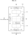
- FIGS. 3A through 3D illustrate examples of a rear side of a battery management apparatus 110.
- a processor 111 and IR communicators 320 through 327 are located on a board 310 of the battery management apparatus 110.
- the board 310 corresponds to a printed circuit board (PCB).
- PCB printed circuit board
- the board 310 includes a plurality of holes, for example, holes 311, 312 and 313. In other words, the holes 311 through 313 are formed in the board 310.
- a battery cell 120 includes a cathode portion, a vent, and an anode portion, which will be described below.
- the holes 311, 312 and 313 respectively correspond to the cathode portion, the vent, and the anode portion of the battery cell 120.
- the processor 111 is installed or located between the holes 312 and 313, as shown in FIG. 3A .
- examples are not limited thereto, and the processor 111 may be installed or located in any location of the board 310.
- the IR communicators 320 through 327 perform IR communications in lateral directions of the battery management apparatus 110.
- the IR communicators 320 and 321 included in a first IR communicator set perform an IR communication in a first lateral direction.
- the IR communicator 320 transmits data to a neighboring battery management apparatus at a location A via the IR communication
- the IR communicator 321 receives data from the neighboring battery management apparatus at the location A via the IR communication.
- IR communicators 322 and 323 included in a second IR communicator set perform an IR communication in a second lateral direction
- IR communicators 324 and 325 included in a third IR communicator set perform an IR communication in a third lateral direction
- IR communicators 326 and 327 included in a fourth IR communicator set perform an IR communication in a fourth lateral direction.
- the IR communicators shown above are arranged in various forms.
- the IR communicators 320 and 321 are located to correspond to a first side (i.e., a right side as viewed from the rear side of FIG. 3A ) of the battery management apparatus 100 (or the board 310), and the IR communicators 322 and 323 are located to correspond to a second side (i.e., a lower side as viewed from the rear side of FIG. 3A ) of the battery management apparatus 110 (or the board 310).
- the IR communicators 320 and 321 may be located near or along the first side of the board 310, and the IR communicators 322 and 323 may be located near or along the second side of the board 310.
- the IR communicators 324 and 325 are located to correspond to a third side (i.e., a left side as viewed from the rear side of FIG. 3A ) of the battery management apparatus 110 (or the board 310), and the IR communicators 326 and 327 are located to correspond to a fourth side (i.e., an upper side as viewed from the rear side of FIG. 3A ) of the battery management apparatus 110 (or the board 310).
- the IR communicators 324 and 325 may be located near or along the third side of the board 310, and the IR communicators 326 and 327 may be located near or along the fourth side of the board 310.
- the IR communicators 320 and 321 are spaced apart from each other by a distance d 1
- the IR communicators 322 and 323 are spaced apart from each other by a distance d 2
- the IR communicators 324 and 325 are spaced apart from each other by a distance d 3
- the IR communicators 326 and 327 are spaced apart from each other by a distance d 4 .
- the IR communicators 320 and 321 are arranged near the first side, the IR communicator 320 is located at a distance of d 1 /2 above a first reference line, and the IR communicator 321 is located at a distance of d 1 /2 below the first reference line.
- the IR communicators 322 and 323 are arranged near the second side, the IR communicator 322 is located at a distance of d 2 /2 to the right of a second reference line, and the IR communicator 323 is located at a distance of d 2 /2 to the left of the second reference line.
- the IR communicators 324 and 325 are arranged near the third side, the IR communicator 324 is located at a distance of d 3 /2 below the first reference line, and the IR communicator 325 is located at a distance of d 3 /2 above the first reference line. Also, the IR communicators 326 and 327 are arranged near the fourth side, the IR communicator 326 is located at a distance of d 4 /2 to the left of the second reference line, and the IR communicator 327 is located at a distance of d 4 /2 to the right of the second reference line.
- the first reference line is a horizontal line of the board 310 and corresponds to, for example, a line passing through a central portion of the first side and a central portion of the third side.
- the second reference line is a vertical line of the board 310, and corresponds to, for example, a line passing through a central portion of the second side and a central portion of the fourth side.
- the distances d 1 , d 2 , d 3 , and d 4 are equal to each other.
- the distances d 1 and d 3 may be equal to each other, and the distances d 2 and d 4 may be equal to each other, however, the distances d 1 and d 3 may be different from the distances d 2 and d 4 .
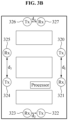
- distances d 1 and d 3 are greater than distances d 2 and d 4 .
- IR communicators 320 through 327 are not limited to the examples of FIGS. 3A and 3B , and may vary.
- IR communicators 320 and 325 are located between holes 311 and 312, and IR communicators 321 and 324 are located between holes 312 and 313.
- IR communicators 320 and 327 are located at an upper right corner, and IR communicators 321 and 322 are located at a lower right corner.
- IR communicators 323 and 324 are located at a lower left corner, and IR communicators 325 and 326 are located at an upper left corner.
- FIGS. 3A through 3D The examples of the rear side of the battery management apparatus 110 described above with reference to FIGS. 3A through 3D are not limited to the description of FIGS. 3A through 3D .
- Other arrangements of locations or an arrangement of the IR communicators 320 through 327 may be used without departing from the scope of the illustrative examples described.
- FIGS. 4 through 6 illustrate an example of a battery management apparatus installed in a battery cell.
- a battery management apparatus 110 is mounted on a top of a battery cell 120.
- Aboard 310 includes holes 311, 312 and 313 that respectively correspond to a cathode portion 121, a vent 122 and an anode portion 123 of the battery cell 120, as described above with reference to FIG. 3A . Accordingly, the battery management apparatus 110 is mounted on the top of the battery cell 120. A rear side of the battery management apparatus 110 faces the top of the battery cell 120.
- the battery management apparatus 110 is installed on, for example, a side of the battery cell 120.
- at least one or all of the holes 311 through 313 may not be formed in the board 310.
- FIG. 5 illustrates the top of the battery cell 120 on which the battery management apparatus 110 is mounted.
- a processor 111 and IR communicators 320 through 327 are represented by dashed lines, which indicate that the processor 111 and the IR communicators 320 through 327 are installed on a rear side of the board 310.
- the processor 111 and the IR communicators 320 through 327 may be installed on a front side of the board 310.
- FIG. 6 illustrates a left side of the battery cell 120 on which the battery management apparatus 110 is mounted.
- a cathode terminal and an anode terminal of the battery cell 120 do not protrude from the battery management apparatus 110.
- the cathode terminal and the anode terminal of the battery cell 120 may protrude from the battery management apparatus 110.
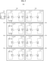
- FIGS. 7 and 8 illustrate examples of a battery module.
- a battery module 700 a plurality of battery cells, and battery management apparatuses 110-1 through 110-12 are arranged in parallel.
- the battery cells are electrically connected in series.
- each of the battery management apparatuses 110-1 through 110-12 performs an IR communication with a neighboring battery management apparatus.
- a battery management apparatus 110-1 transmits sensing data of the battery management apparatus 110-1 to a battery management apparatus 110-2 using an IR communicator for transmission located near a right side of the battery management apparatus 110-1.
- the battery management apparatus 110-2 receives the sensing data using an IR communicator for reception located near a left side of the battery management apparatus 110-2.
- each of the battery management apparatuses 110-1 through 110-12 performs an IR communication with a neighboring battery management apparatus.
- battery cells and battery management apparatuses 110-1 through 110-12 are physically arranged in a form of a 4 ⁇ 3 matrix.
- the battery cells are electrically connected in series.
- each of the battery management apparatuses 110-1 through 110-12 performs an IR communication with a neighboring battery management apparatus.
- a battery management apparatus 110-10 receives sensing data from a battery management apparatus 110-11 using an IR communicator for reception located near a left side of the battery management apparatus 110-10, and transmits sensing data of the battery management apparatus 110-10 to a battery management apparatus 110-9 using an IR communicator for transmission located near a lower side of the battery management apparatus 110-10.
- each of the battery management apparatuses 110-1 through 110-12 performs an IR communication with a neighboring battery management apparatus.
- FIGS. 7 and 8 The above arrangements of the battery cells of FIGS. 7 and 8 are merely examples, and are not limited to the description of FIGS. 7 and 8 .
- each of the battery management apparatuses 110-1 through 110-12 performs an IR communication in various directions, instead of using an antenna.
- the battery management apparatuses 110-1 through 110-12 are applicable to various arrangements of the battery cells, instead of changing a structure of each of the battery management apparatuses 110-1 through 110-12.
- the battery management apparatuses 110-1 through 110-12 are applicable to various configurations of the battery cells, instead of changing a structure of each of the battery management apparatuses 110-1 through 110-12.
- FIG. 9 illustrates an example of a battery pack 900.
- the battery pack 900 includes a master battery management apparatus 910, and a plurality of battery modules, for example, battery modules 920 through 980.
- the battery modules 920 through 980 include battery cells and battery management apparatuses 110-1 through 110-96.
- Each of the battery modules 920 through 980 corresponds to, for example, the above-described battery module 700 or 800. Also, the battery modules 920 through 980 are electrically connected in series.
- the battery management apparatuses 110-1 through 110-96 may be referred to as "slave battery management apparatuses.”
- the master battery management apparatus 910 controls the battery management apparatuses 110-1 through 110-96. For example, referring to FIG. 9 , when the master battery management apparatus 910 sends a control command (for example, a sensing command) to a battery management apparatus 110-1, the battery management apparatus 110-1 transmits the control command via an IR communication to neighboring battery management apparatuses (for example, a battery management apparatus 110-25, and a battery management apparatus located on a right side of the battery management apparatus 110-1). In this example, each of battery management apparatuses that receive the control command from the battery management apparatus 110-1 sends the control command via an IR communication to a neighboring battery management apparatus of each of battery management apparatuses.
- a control command for example, a sensing command
- neighboring battery management apparatuses for example, a battery management apparatus 110-25, and a battery management apparatus located on a right side of the battery management apparatus 110-1.
- each of battery management apparatuses that receive the control command from the battery management apparatus 110-1 sends the control command via an
- the control command is transmitted to all the battery management apparatuses 110-1 through 110-96.
- a communication between the master battery management apparatus 910 and each of the battery management apparatuses 110-1 through 110-96 is merely an example and is not limited to the above description.
- the master battery management apparatus 910 receives data of each of the battery management apparatuses 110-1 through 110-96.
- each of battery management apparatuses 110-2 through 110-96 transmits sensing data of each of the battery management apparatuses 110-2 through 110-96 via an IR communication to a neighboring battery management apparatus.
- sensing data of each of the battery management apparatuses 110-2 through 110-96 is directed to the battery management apparatus 110-1.
- the battery management apparatus 110-1 acquires sensing data of each of the battery management apparatuses 110-2 through 110-96.
- the battery management apparatus 110-1 transmits sensing data of the battery management apparatus 110-1 and sensing data of each of the battery management apparatuses 110-2 through 110-96 to the master battery management apparatus 910.
- the master battery management apparatus 910 determines state information (for example, an SOC, or an SOH) of each of the battery cells based on sensing data of each of the battery management apparatuses 110-1 through 110-96.
- the master battery management apparatus 910 determines state information of each of the battery modules 920 through 990, and state information of the battery pack 900.
- the battery pack 900 is applicable to various devices, such as, for example, a vehicle, a walking assistance device, a wearable device, a security device, a robot, a mobile terminal, an energy storage system (ESS), and various Internet of Things (IoT) devices that use the batteries as a power source.
- devices such as, for example, a vehicle, a walking assistance device, a wearable device, a security device, a robot, a mobile terminal, an energy storage system (ESS), and various Internet of Things (IoT) devices that use the batteries as a power source.
- ESS energy storage system
- IoT Internet of Things
- the vehicle described herein refers to any mode of transportation, delivery, or communication such as, for example, an automobile, a truck, a tractor, a scooter, a motorcycle, a cycle, an amphibious vehicle, a snowmobile, a boat, a public transit vehicle, a bus, a monorail, a train, a tram, an autonomous or automated driving vehicle, an intelligent vehicle, a self-driving vehicle, an unmanned aerial vehicle, an electric vehicle (EV), a hybrid vehicle, or a drone.
- any mode of transportation, delivery, or communication such as, for example, an automobile, a truck, a tractor, a scooter, a motorcycle, a cycle, an amphibious vehicle, a snowmobile, a boat, a public transit vehicle, a bus, a monorail, a train, a tram, an autonomous or automated driving vehicle, an intelligent vehicle, a self-driving vehicle, an unmanned aerial vehicle, an electric vehicle (EV), a hybrid vehicle, or a drone.
- EV electric vehicle
- FIGS. 10 and 11 illustrate an example of a fixer 1000.
- the fixer 1000 (for example, a fixing fence) is located between a battery management apparatus 110 and a battery cell 120.
- the fixer 1000 is located between each battery cell and each of the battery management apparatuses 110-1 through 110-12 of FIGS. 7 and 8 , or located between each battery cell and each of the battery management apparatuses 110-1 through 110-96 of FIG. 9 .
- the fixer 1000 more firmly fixes the battery management apparatus 110 to the battery cell 120. Also, the fixer 1000 does not cover IR communicators, for example, the IR communicators 112-1 through 112-4 of FIG. 2 , or the IR communicators 320 through 327 of FIGS. 3A through 3D .
- the fixer 1000 blocks IR light output from a battery management apparatus that does not face the battery management apparatus 110.
- the battery management apparatus 110-10 outputs IR light using an IR communicator located near a lower side of the battery management apparatus 110-10 to transmit data to the battery management apparatus 110-9 that faces the battery management apparatus 110-10.
- the IR light is also directed to the battery management apparatus 110-8 that does not face the battery management apparatus 110-10.
- a blocker of the battery management apparatus 110-8 blocks the IR light from battery management apparatus 110-10 to prevent an IR communicator of the battery management apparatus 110-8 from receiving the IR light from battery management apparatus 110-10.
- a battery management apparatus 110-13 in a battery module 930 outputs IR light using an IR communicator located near a left side of the battery management apparatus 110-13 to transmit data to a battery management apparatus 110-12 that faces the battery management apparatus 110-13.
- the IR light is also directed to a battery management apparatus 110-36 that does not face the battery management apparatus 110-13, and a blocker of the battery management apparatus 110-36 blocks IR light from battery management apparatus 110-13.
- the fixer 1000 may be black in color. However, black is merely an example, and a color of the fixer 1000 is not limited to being black.
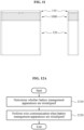
- FIGS. 12A through 15 illustrate examples of a communication performed in response to battery management apparatuses being misaligned.
- a battery management apparatus 110 determines whether the battery management apparatus 110 is misaligned with another battery management apparatus.
- a misalignment indicates that IR communicators at each of edges that face in battery management apparatuses adjacent to each other do not properly face each other.
- FIG. 12B IR communicators located near a right side of a battery management apparatus A face IR communicators located near a left side of a battery management apparatus, which indicates that the battery management apparatuses A and B are aligned.
- an example in which an IR communicator for reception located near the right side of the battery management apparatus A faces an IR communicator for transmission located near the left side of the battery management apparatus B and in which an IR communicator for transmission located near the right side of the battery management apparatus A faces an IR communicator for reception located near the left side of the battery management apparatus B, indicates that the battery management apparatuses A and B are aligned.
- IR communicators located near a right side of a battery management apparatus A do not face IR communicators located near a left side of a battery management apparatus B, which indicates that the battery management apparatuses A and B are misaligned.
- battery management apparatuses may be misaligned due to an impact on the battery pack 900.
- a wire communication is performed in operation 1220.
- FIG. 12C since an IR communicator for reception located near the right side of the battery management apparatus A does not face an IR communicator for transmission located near the left side of the battery management apparatus B, it is difficult to accurately receive IR light output from the IR communicator for transmission.
- a master battery management apparatus 910 and a battery management apparatus 110-1 are misaligned.
- IR communicators located near a right side of the master battery management apparatus 910 do not face IR communicators located near a left side of the battery management apparatus 110-1.
- the battery management apparatus 110-1 performs a wire communication.
- the wire communication includes, for example, a controller area network (CAN) communication.
- CAN controller area network
- a master battery management apparatus 910 and a battery management apparatus 110-1 are misaligned, and battery management apparatuses 110-1 and 110-25 are misaligned.
- battery management apparatuses 110-25 and 110-49 are misaligned, and battery management apparatuses 110-49 and 110-73 are misaligned.
- each of the battery management apparatuses 110-1, 110-25, 110-49, and 110-73 performs a wire communication with the master battery management apparatus 910.
- a master battery management apparatus 910 and a battery management apparatus 110-1 are misaligned, and battery management apparatuses 110-1 and 110-25 are misaligned.
- battery management apparatuses 110-25 and 110-49 are misaligned, and battery management apparatuses 110-49 and 110-73 are misaligned.
- battery management apparatuses 110-12 and 110-13 are misaligned, and battery management apparatuses 110-36 and 110-37 are misaligned.
- Battery management apparatuses 110-60 and 110-61 are misaligned, and battery management apparatuses 110-84 and 110-85 are misaligned.
- each of the battery management apparatuses 110-1, 110-12, 110-13, 110-25, 110-36, 110-37, 110-49, 110-60, 110-61, 110-73, 110-84, and 110-85 performs a wire communication with the master battery management apparatus 910.
- a wire communication is performed despite a misalignment occurring in the battery pack 900 as described above with reference to FIGS. 12A through 15 , and thus a control command of the master battery management apparatus 910 is transferred to the battery management apparatuses 110-1 through 110-96, and data of each of the battery management apparatuses 110-1 through 110-96 is transmitted to the master battery management apparatus 910.
- FIGS. 1 through 11 is also applicable to the examples of FIGS. 12A through 15 , and thus is not repeated herein.
- a battery module-based battery management system (BMS) and a battery cell-based BMS according to a related art each have a single structure, it is difficult to apply the existing battery module-based BMS and the existing battery cell-based BMS to various arrangements of battery cells. For example, when an arrangement and/or a number of battery cells included in a battery module with a BMS according to a related art is changed, the BMS needs to be redesigned. Also, because a battery cell with a BMS according to a related art performs a wireless communication requiring an antenna, an antenna layout needs to be changed when an arrangement of battery cells is changed.
- a battery management apparatus includes IR communicators that face at least one neighboring battery management apparatus, and thus it is possible to apply the battery management apparatus to a battery module, instead of changing a structure of the battery management apparatus, despite a change in an arrangement and/or a number of battery cells included in the battery module.
- the battery management apparatus 110, the processor 111, and other apparatuses, units, modules, devices, and other components described herein are implemented by hardware components.
- hardware components that may be used to perform the operations described in this application where appropriate include controllers, sensors, generators, drivers, memories, comparators, arithmetic logic units, adders, subtractors, multipliers, dividers, integrators, and any other electronic components configured to perform the operations described in this application.
- one or more of the hardware components that perform the operations described in this application are implemented by computing hardware, for example, by one or more processors or computers.
- a processor or computer may be implemented by one or more processing elements, such as an array of logic gates, a controller and an arithmetic logic unit, a digital signal processor, a microcomputer, a programmable logic controller, a field-programmable gate array, a programmable logic array, a microprocessor, or any other device or combination of devices that is configured to respond to and execute instructions in a defined manner to achieve a desired result.
- a processor or computer includes, or is connected to, one or more memories storing instructions or software that are executed by the processor or computer.
- Hardware components implemented by a processor or computer may execute instructions or software, such as an operating system (OS) and one or more software applications that run on the OS, to perform the operations described in this application.
- OS operating system
- the hardware components may also access, manipulate, process, create, and store data in response to execution of the instructions or software.
- processor or “computer” may be used in the description of the examples described in this application, but in other examples multiple processors or computers may be used, or a processor or computer may include multiple processing elements, or multiple types of processing elements, or both.
- a single hardware component or two or more hardware components may be implemented by a single processor, or two or more processors, or a processor and a controller.
- One or more hardware components may be implemented by one or more processors, or a processor and a controller, and one or more other hardware components may be implemented by one or more other processors, or another processor and another controller.
- One or more processors may implement a single hardware component, or two or more hardware components.
- a hardware component may have any one or more of different processing configurations, examples of which include a single processor, independent processors, parallel processors, single-instruction single-data (SISD) multiprocessing, single-instruction multiple-data (SIMD) multiprocessing, multiple-instruction single-data (MISD) multiprocessing, and multiple-instruction multiple-data (MIMD) multiprocessing.
- SISD single-instruction single-data
- SIMD single-instruction multiple-data
- MIMD multiple-instruction multiple-data
Landscapes
- Engineering & Computer Science (AREA)
- Chemical & Material Sciences (AREA)
- General Chemical & Material Sciences (AREA)
- Electrochemistry (AREA)
- Chemical Kinetics & Catalysis (AREA)
- Manufacturing & Machinery (AREA)
- Power Engineering (AREA)
- General Physics & Mathematics (AREA)
- Physics & Mathematics (AREA)
- Life Sciences & Earth Sciences (AREA)
- Sustainable Development (AREA)
- Sustainable Energy (AREA)
- Transportation (AREA)
- Mechanical Engineering (AREA)
- Microelectronics & Electronic Packaging (AREA)
- Computer Networks & Wireless Communication (AREA)
- Battery Mounting, Suspending (AREA)
Description
- The following description relates to a battery management apparatus, a battery module, a battery pack and a method of operating a battery management apparatus.
- A battery module includes one or more battery cells, and a plurality of battery modules form a battery pack. A battery management system (BMS) may be installed in each battery module, which may correspond to a battery module-based BMS. Also, a BMS may be installed in each battery cell, which may correspond to a battery cell-based BMS.
EP 2 922 171 A2 , discloses a battery management system that manages a battery pack and includes N battery management units configured to manage secondary batteries included in the battery pack. Hereby, N is a natural number greater than or equal to 2. N communication lines, which are electrically connected to each battery management unit, are used to transmit data to an external device, which controls the battery management system. The transmission of data may be performed by means of a photo coupler including an infrared light emitting source and a light detector.
US 2013/0253715 A1 discloses: a power storage system including n number of slave BMSs for transmitting data associated with an electric characteristic value of battery cells, included in battery modules managed by the slave BMSs, through slave communication networks; m number of master BMSs for primarily processing the data associated with an electric characteristic value of battery cells, transmitted through the slave communication networks, and transmitting the primarily processed data through a master communication network; and a super master BMS for secondarily processing the data transmitted through the master communication network. Since the data transmitted from each slave BMS are processed in a master BMSs, the amount of data loaded on a communication line may decrease. Therefore, even though the capacity of a power storage system increases, rapid data collection and data control may be achieved. - It is the object of the present application to provide a method and battery management system, which can be flexibly applied to different arrangements of battery cells.
This Object is solved by the subject matter of the independent claims.
Preferred embodiments of the present invention are defined by the dependent claims. - This Summary is provided to introduce a selection of concepts in a simplified form that are further described below in the Detailed Description. This Summary is not intended to identify key features or essential features of the claimed subject matter, nor is it intended to be used as an aid in determining the scope of the claimed subject matter.
- In one general aspect, there is provided a battery management apparatus including a processor configured to collect sensing data of a battery using a sensor, and infrared (IR) communicators located to face a neighboring battery management apparatus of the battery management apparatus, wherein the processor is configured to transmit the collected sensing data to the neighboring battery management apparatus using one of the IR communicators.
- The battery management apparatus may include a hole corresponding to each of electrodes of the battery and a hole corresponding to a vent of the battery.
- The processor may be located between the hole corresponding to the vent and a hole corresponding to one of the electrodes.
- The IR communicators are located adjacent to sides of a board of the battery management apparatus.
- The IR communicators include a first IR communicator set configured to perform an IR communication in a first lateral direction of the battery management apparatus, a second IR communicator set configured to perform an IR communication in a second lateral direction of the battery management apparatus, a third IR communicator set configured to perform an IR communication in a third lateral direction of the battery management apparatus, and a fourth IR communicator set configured to perform an IR communication in a fourth lateral direction of the battery management apparatus.
- Each of the first IR communicator set through the fourth IR communicator set may include an IR communicator for transmission and an IR communicator for reception.
- An IR communicator for transmission of each of the first IR communicator set through the fourth IR communicator set may be spaced apart from an IR communicator for reception of each of the first IR communicator set through the fourth IR communicator set.
- In another general aspect, there is provided a battery module according to claim 6.
- A board of the each of the battery management apparatus may include a hole corresponding to each of electrodes of the corresponding battery and a hole corresponding to a vent of the corresponding battery.
- The processor may be located between the hole corresponding to the vent and a hole corresponding to one of the electrodes.
- The IR communicators are located adjacent to sides of a board of each of the battery management apparatuses.
- The IR communicators include first IR communicator set configured to perform an IR communication in a first lateral direction of each of the battery management apparatuses, a second IR communicator set configured to perform an IR communication in a second lateral direction of each of the battery management apparatuses, a third IR communicator set configured to perform an IR communication in a third lateral direction of each of the battery management apparatuses, and a fourth IR communicator set configured to perform an IR communication in a fourth lateral direction of each of the battery management apparatuses.
- The first IR communicator set through the fourth IR communicator set may include an IR communicator for transmission and an IR communicator for reception.
- An IR communicator for transmission of each of the first IR communicator set through the fourth IR communicator set may be spaced apart from an IR communicator for reception of each of the first IR communicator set through the fourth IR communicator set.
- The battery module may include fixers that are configured to fix each of the battery management apparatuses to the corresponding battery.
- Each of the fixers selectively blocks IR light output from the battery management apparatuses that may not be adjacent to the corresponding battery management apparatus.
- In another general aspect, there is provided a battery pack according to claim 7.
- Other features and aspects will be apparent from the following detailed description, the drawings, and the claims.
-
-
FIGS. 1 and2 illustrate an example of a battery management apparatus. -
FIGS. 3A through 3D illustrate examples of a rear side of a battery management apparatus. -
FIGS. 4 through 6 illustrate an example of a battery management apparatus installed in a battery cell. -
FIGS. 7 and8 illustrate examples of a battery module. -
FIG. 9 illustrates an example of a battery pack. -
FIGS. 10 and11 illustrate an example of a fixer. -
FIGS. 12A through 15 illustrate examples of a communication performed in response to battery management apparatuses being misaligned in a battery pack. - Throughout the drawings and the detailed description, unless otherwise described or provided, the same drawing reference numerals will be understood to refer to the same elements, features, and structures. The drawings may not be to scale, and the relative size, proportions, and depiction of elements in the drawings may be exaggerated for clarity, illustration, and convenience.
-
FIGS. 1 and2 illustrate an example of abattery management apparatus 110. - Referring to
FIG. 1 , thebattery management apparatus 110 includes aprocessor 111 and infrared (IR)communicators 112. - The
processor 111 performs various functions of thebattery management apparatus 110. For example, theprocessor 111 collects sensing data by sensing abattery cell 120, and transmits the collected sensing data to a neighboring battery management apparatus via one of theIR communicators 112. The sensing data includes one or more of data such as, for example, voltage data, current data and temperature data of thebattery cell 120. Depending on examples, theprocessor 111 may estimate a state of charge (SOC) or a state of health (SOH) of thebattery cell 120 based on sensing data of thebattery cell 120. - The
IR communicators 112 face at least one neighboring battery management apparatus of thebattery management apparatus 110. For example, referring toFIG. 2 , an IR communicator 112-1 faces a neighboring battery management apparatus at a location A, and an IR communicator 112-2 faces a neighboring battery management apparatus at a location B. Also, an IR communicator 112-3 faces a neighboring battery management apparatus at a location C, and an IR communicator 112-4 faces a neighboring battery management apparatus at a location D. - Through the IR communicators 112-1 through 112-4, the
battery management apparatus 110 performs IR communications in various directions. -
FIGS. 3A through 3D illustrate examples of a rear side of abattery management apparatus 110. - In an example of
FIG. 3A , aprocessor 111 andIR communicators 320 through 327 are located on aboard 310 of thebattery management apparatus 110. - In an example, the
board 310 corresponds to a printed circuit board (PCB). - The
board 310 includes a plurality of holes, for example, holes 311, 312 and 313. In other words, theholes 311 through 313 are formed in theboard 310. Abattery cell 120 includes a cathode portion, a vent, and an anode portion, which will be described below. Theholes battery cell 120. - In an example, the
processor 111 is installed or located between theholes FIG. 3A . However, examples are not limited thereto, and theprocessor 111 may be installed or located in any location of theboard 310. - The
IR communicators 320 through 327 perform IR communications in lateral directions of thebattery management apparatus 110. For example, theIR communicators IR communicator 320 transmits data to a neighboring battery management apparatus at a location A via the IR communication, and theIR communicator 321 receives data from the neighboring battery management apparatus at the location A via the IR communication. Similarly,IR communicators IR communicators IR communicators - Depending on examples, for IR communications in the lateral directions of the
battery management apparatus 110, orvarious directions, the IR communicators shown above are arranged in various forms. - Referring to
FIG. 3A , theIR communicators FIG. 3A ) of the battery management apparatus 100 (or the board 310), and theIR communicators FIG. 3A ) of the battery management apparatus 110 (or the board 310). For example, theIR communicators board 310, and theIR communicators board 310. Also, theIR communicators FIG. 3A ) of the battery management apparatus 110 (or the board 310), and theIR communicators FIG. 3A ) of the battery management apparatus 110 (or the board 310). For example, theIR communicators board 310, and theIR communicators board 310. - In the example of
FIG. 3A , theIR communicators IR communicators IR communicators IR communicators IR communicators IR communicator 320 is located at a distance of d1/2 above a first reference line, and theIR communicator 321 is located at a distance of d1/2 below the first reference line. TheIR communicators IR communicator 322 is located at a distance of d2/2 to the right of a second reference line, and theIR communicator 323 is located at a distance of d2/2 to the left of the second reference line. TheIR communicators IR communicator 324 is located at a distance of d3/2 below the first reference line, and theIR communicator 325 is located at a distance of d3/2 above the first reference line. Also, theIR communicators IR communicator 326 is located at a distance of d4/2 to the left of the second reference line, and theIR communicator 327 is located at a distance of d4/2 to the right of the second reference line. - In an example, the first reference line is a horizontal line of the
board 310 and corresponds to, for example, a line passing through a central portion of the first side and a central portion of the third side. The second reference line is a vertical line of theboard 310, and corresponds to, for example, a line passing through a central portion of the second side and a central portion of the fourth side. - In the example of
FIG. 3A , the distances d1, d2, d3, and d4 are equal to each other. Depending on examples, the distances d1 and d3 may be equal to each other, and the distances d2 and d4 may be equal to each other, however, the distances d1 and d3 may be different from the distances d2 and d4. For example, as shown inFIG. 3B , distances d1 and d3 are greater than distances d2 and d4. - Locations or an arrangement of the
IR communicators 320 through 327 are not limited to the examples ofFIGS. 3A and3B , and may vary. Referring toFIG. 3C ,IR communicators holes IR communicators holes FIG. 3D ,IR communicators IR communicators IR communicators IR communicators - The examples of the rear side of the
battery management apparatus 110 described above with reference toFIGS. 3A through 3D are not limited to the description ofFIGS. 3A through 3D . Other arrangements of locations or an arrangement of theIR communicators 320 through 327 may be used without departing from the scope of the illustrative examples described. -
FIGS. 4 through 6 illustrate an example of a battery management apparatus installed in a battery cell. - Referring to
FIG. 4 , abattery management apparatus 110 is mounted on a top of abattery cell 120. Aboard 310 includesholes cathode portion 121, avent 122 and ananode portion 123 of thebattery cell 120, as described above with reference toFIG. 3A . Accordingly, thebattery management apparatus 110 is mounted on the top of thebattery cell 120. A rear side of thebattery management apparatus 110 faces the top of thebattery cell 120. However, examples are not limited thereto, and thebattery management apparatus 110 is installed on, for example, a side of thebattery cell 120. For example, when thebattery management apparatus 110 is designed to be installed on a side of thebattery cell 120, at least one or all of theholes 311 through 313 may not be formed in theboard 310. -
FIG. 5 illustrates the top of thebattery cell 120 on which thebattery management apparatus 110 is mounted. Aprocessor 111 andIR communicators 320 through 327 are represented by dashed lines, which indicate that theprocessor 111 and theIR communicators 320 through 327 are installed on a rear side of theboard 310. Depending on examples, theprocessor 111 and theIR communicators 320 through 327 may be installed on a front side of theboard 310. -
FIG. 6 illustrates a left side of thebattery cell 120 on which thebattery management apparatus 110 is mounted. InFIG. 6 , a cathode terminal and an anode terminal of thebattery cell 120 do not protrude from thebattery management apparatus 110. Depending on examples, the cathode terminal and the anode terminal of thebattery cell 120 may protrude from thebattery management apparatus 110. -
FIGS. 7 and8 illustrate examples of a battery module. - Referring to
FIG. 7 , in abattery module 700, a plurality of battery cells, and battery management apparatuses 110-1 through 110-12 are arranged in parallel. The battery cells are electrically connected in series. - In
FIG. 7 , each of the battery management apparatuses 110-1 through 110-12 performs an IR communication with a neighboring battery management apparatus. For example, a battery management apparatus 110-1 transmits sensing data of the battery management apparatus 110-1 to a battery management apparatus 110-2 using an IR communicator for transmission located near a right side of the battery management apparatus 110-1. The battery management apparatus 110-2 receives the sensing data using an IR communicator for reception located near a left side of the battery management apparatus 110-2. Similarly, each of the battery management apparatuses 110-1 through 110-12 performs an IR communication with a neighboring battery management apparatus. - Referring to
FIG. 8 , in abattery module 800, battery cells and battery management apparatuses 110-1 through 110-12 are physically arranged in a form of a 4 × 3 matrix. The battery cells are electrically connected in series. - In
FIG. 8 , each of the battery management apparatuses 110-1 through 110-12 performs an IR communication with a neighboring battery management apparatus. For example, a battery management apparatus 110-10 receives sensing data from a battery management apparatus 110-11 using an IR communicator for reception located near a left side of the battery management apparatus 110-10, and transmits sensing data of the battery management apparatus 110-10 to a battery management apparatus 110-9 using an IR communicator for transmission located near a lower side of the battery management apparatus 110-10. Similarly, each of the battery management apparatuses 110-1 through 110-12 performs an IR communication with a neighboring battery management apparatus. - The above arrangements of the battery cells of
FIGS. 7 and8 are merely examples, and are not limited to the description ofFIGS. 7 and8 . - As described above, each of the battery management apparatuses 110-1 through 110-12 performs an IR communication in various directions, instead of using an antenna. Thus, the battery management apparatuses 110-1 through 110-12 are applicable to various arrangements of the battery cells, instead of changing a structure of each of the battery management apparatuses 110-1 through 110-12. In other words, the battery management apparatuses 110-1 through 110-12 are applicable to various configurations of the battery cells, instead of changing a structure of each of the battery management apparatuses 110-1 through 110-12.
-
FIG. 9 illustrates an example of abattery pack 900. - Referring to
FIG. 9 , thebattery pack 900 includes a masterbattery management apparatus 910, and a plurality of battery modules, for example,battery modules 920 through 980. Thebattery modules 920 through 980 include battery cells and battery management apparatuses 110-1 through 110-96. Each of thebattery modules 920 through 980 corresponds to, for example, the above-describedbattery module battery modules 920 through 980 are electrically connected in series. - The battery management apparatuses 110-1 through 110-96 may be referred to as "slave battery management apparatuses."
- The master
battery management apparatus 910 controls the battery management apparatuses 110-1 through 110-96. For example, referring toFIG. 9 , when the masterbattery management apparatus 910 sends a control command (for example, a sensing command) to a battery management apparatus 110-1, the battery management apparatus 110-1 transmits the control command via an IR communication to neighboring battery management apparatuses (for example, a battery management apparatus 110-25, and a battery management apparatus located on a right side of the battery management apparatus 110-1). In this example, each of battery management apparatuses that receive the control command from the battery management apparatus 110-1 sends the control command via an IR communication to a neighboring battery management apparatus of each of battery management apparatuses. Through the above IR communications between the battery management apparatuses 110-1 through 110-96, the control command is transmitted to all the battery management apparatuses 110-1 through 110-96. A communication between the masterbattery management apparatus 910 and each of the battery management apparatuses 110-1 through 110-96 is merely an example and is not limited to the above description. - The master
battery management apparatus 910 receives data of each of the battery management apparatuses 110-1 through 110-96. For example, each of battery management apparatuses 110-2 through 110-96 transmits sensing data of each of the battery management apparatuses 110-2 through 110-96 via an IR communication to a neighboring battery management apparatus. Through IR communication, sensing data of each of the battery management apparatuses 110-2 through 110-96 is directed to the battery management apparatus 110-1. In other words, through IR communications between the battery management apparatuses 110-1 through 110-96, the battery management apparatus 110-1 acquires sensing data of each of the battery management apparatuses 110-2 through 110-96. The battery management apparatus 110-1 transmits sensing data of the battery management apparatus 110-1 and sensing data of each of the battery management apparatuses 110-2 through 110-96 to the masterbattery management apparatus 910. For example, the masterbattery management apparatus 910 determines state information (for example, an SOC, or an SOH) of each of the battery cells based on sensing data of each of the battery management apparatuses 110-1 through 110-96. Also, the masterbattery management apparatus 910 determines state information of each of thebattery modules 920 through 990, and state information of thebattery pack 900. - The
battery pack 900 is applicable to various devices, such as, for example, a vehicle, a walking assistance device, a wearable device, a security device, a robot, a mobile terminal, an energy storage system (ESS), and various Internet of Things (IoT) devices that use the batteries as a power source. The vehicle described herein refers to any mode of transportation, delivery, or communication such as, for example, an automobile, a truck, a tractor, a scooter, a motorcycle, a cycle, an amphibious vehicle, a snowmobile, a boat, a public transit vehicle, a bus, a monorail, a train, a tram, an autonomous or automated driving vehicle, an intelligent vehicle, a self-driving vehicle, an unmanned aerial vehicle, an electric vehicle (EV), a hybrid vehicle, or a drone. -
FIGS. 10 and11 illustrate an example of afixer 1000. - Referring to
FIGS. 10 and11 , the fixer 1000 (for example, a fixing fence) is located between abattery management apparatus 110 and abattery cell 120. For example, thefixer 1000 is located between each battery cell and each of the battery management apparatuses 110-1 through 110-12 ofFIGS. 7 and8 , or located between each battery cell and each of the battery management apparatuses 110-1 through 110-96 ofFIG. 9 . - The
fixer 1000 more firmly fixes thebattery management apparatus 110 to thebattery cell 120. Also, thefixer 1000 does not cover IR communicators, for example, the IR communicators 112-1 through 112-4 ofFIG. 2 , or theIR communicators 320 through 327 ofFIGS. 3A through 3D . - The
fixer 1000 blocks IR light output from a battery management apparatus that does not face thebattery management apparatus 110. In an example, referring toFIG. 8 , the battery management apparatus 110-10 outputs IR light using an IR communicator located near a lower side of the battery management apparatus 110-10 to transmit data to the battery management apparatus 110-9 that faces the battery management apparatus 110-10. In this example, the IR light is also directed to the battery management apparatus 110-8 that does not face the battery management apparatus 110-10. A blocker of the battery management apparatus 110-8 blocks the IR light from battery management apparatus 110-10 to prevent an IR communicator of the battery management apparatus 110-8 from receiving the IR light from battery management apparatus 110-10. Thus, it is possible to prevent the data of the battery management apparatus 110-10 from being transmitted to the battery management apparatus 110-8. In another example, referring toFIG. 9 , a battery management apparatus 110-13 in abattery module 930 outputs IR light using an IR communicator located near a left side of the battery management apparatus 110-13 to transmit data to a battery management apparatus 110-12 that faces the battery management apparatus 110-13. In this example, the IR light is also directed to a battery management apparatus 110-36 that does not face the battery management apparatus 110-13, and a blocker of the battery management apparatus 110-36 blocks IR light from battery management apparatus 110-13. Thus, it is possible to prevent the data of the battery management apparatus 110-13 from being transmitted to the battery management apparatus 110-36. Depending on examples, thefixer 1000 may be black in color. However, black is merely an example, and a color of thefixer 1000 is not limited to being black. -
FIGS. 12A through 15 illustrate examples of a communication performed in response to battery management apparatuses being misaligned. - Referring to
FIG. 12A , inoperation 1210, abattery management apparatus 110 determines whether thebattery management apparatus 110 is misaligned with another battery management apparatus. A misalignment indicates that IR communicators at each of edges that face in battery management apparatuses adjacent to each other do not properly face each other. Referring toFIG. 12B , IR communicators located near a right side of a battery management apparatus A face IR communicators located near a left side of a battery management apparatus, which indicates that the battery management apparatuses A and B are aligned. In other words, an example, in which an IR communicator for reception located near the right side of the battery management apparatus A faces an IR communicator for transmission located near the left side of the battery management apparatus B and in which an IR communicator for transmission located near the right side of the battery management apparatus A faces an IR communicator for reception located near the left side of the battery management apparatus B, indicates that the battery management apparatuses A and B are aligned. Referring toFIG. 12C , IR communicators located near a right side of a battery management apparatus A do not face IR communicators located near a left side of a battery management apparatus B, which indicates that the battery management apparatuses A and B are misaligned. In an example, battery management apparatuses may be misaligned due to an impact on thebattery pack 900. Referring back toFIG. 12A , when thebattery management apparatus 110 is misaligned with a neighboring battery management apparatus, a wire communication is performed inoperation 1220. InFIG. 12C , since an IR communicator for reception located near the right side of the battery management apparatus A does not face an IR communicator for transmission located near the left side of the battery management apparatus B, it is difficult to accurately receive IR light output from the IR communicator for transmission. Similarly, since an IR communicator for reception located near the left side of the battery management apparatus B does not face an IR communicator for transmission located near the right side of the battery management apparatus A, it is difficult to accurately receive IR light output from the IR communicator for transmission. When thebattery management apparatus 110 is misaligned with a neighboring battery management apparatus, a wire communication, instead of an IR communication, is performed. Hereinafter, further examples of performing a communication when a misalignment occurs in abattery pack 900 will be described with reference toFIGS. 13 through 15 . - In an example of
FIG. 13 , a masterbattery management apparatus 910 and a battery management apparatus 110-1 are misaligned. IR communicators located near a right side of the masterbattery management apparatus 910 do not face IR communicators located near a left side of the battery management apparatus 110-1. In this example, because it is difficult for the battery management apparatus 110-1 to perform an IR communication with the masterbattery management apparatus 910, the battery management apparatus 110-1 performs a wire communication. The wire communication includes, for example, a controller area network (CAN) communication. - In an example of
FIG. 14 , a masterbattery management apparatus 910 and a battery management apparatus 110-1 are misaligned, and battery management apparatuses 110-1 and 110-25 are misaligned. Also, battery management apparatuses 110-25 and 110-49 are misaligned, and battery management apparatuses 110-49 and 110-73 are misaligned. In this example, it is difficult to perform IR communications among the battery management apparatuses 110-1, 110-25, 110-49, and 110-73, and also difficult to perform an IR communication between the battery management apparatus 110-1 and the masterbattery management apparatus 910. Thus, each of the battery management apparatuses 110-1, 110-25, 110-49, and 110-73 performs a wire communication with the masterbattery management apparatus 910. - In an example of
FIG. 15 , a masterbattery management apparatus 910 and a battery management apparatus 110-1 are misaligned, and battery management apparatuses 110-1 and 110-25 are misaligned. Also, battery management apparatuses 110-25 and 110-49 are misaligned, and battery management apparatuses 110-49 and 110-73 are misaligned. In addition, battery management apparatuses 110-12 and 110-13 are misaligned, and battery management apparatuses 110-36 and 110-37 are misaligned. Battery management apparatuses 110-60 and 110-61 are misaligned, and battery management apparatuses 110-84 and 110-85 are misaligned. In this example, each of the battery management apparatuses 110-1, 110-12, 110-13, 110-25, 110-36, 110-37, 110-49, 110-60, 110-61, 110-73, 110-84, and 110-85 performs a wire communication with the masterbattery management apparatus 910. - A wire communication is performed despite a misalignment occurring in the
battery pack 900 as described above with reference toFIGS. 12A through 15 , and thus a control command of the masterbattery management apparatus 910 is transferred to the battery management apparatuses 110-1 through 110-96, and data of each of the battery management apparatuses 110-1 through 110-96 is transmitted to the masterbattery management apparatus 910. - The above description of
FIGS. 1 through 11 is also applicable to the examples ofFIGS. 12A through 15 , and thus is not repeated herein. - Because a battery module-based battery management system (BMS) and a battery cell-based BMS according to a related art each have a single structure, it is difficult to apply the existing battery module-based BMS and the existing battery cell-based BMS to various arrangements of battery cells. For example, when an arrangement and/or a number of battery cells included in a battery module with a BMS according to a related art is changed, the BMS needs to be redesigned. Also, because a battery cell with a BMS according to a related art performs a wireless communication requiring an antenna, an antenna layout needs to be changed when an arrangement of battery cells is changed. According to examples, a battery management apparatus includes IR communicators that face at least one neighboring battery management apparatus, and thus it is possible to apply the battery management apparatus to a battery module, instead of changing a structure of the battery management apparatus, despite a change in an arrangement and/or a number of battery cells included in the battery module.
- The
battery management apparatus 110, theprocessor 111, and other apparatuses, units, modules, devices, and other components described herein are implemented by hardware components. Examples of hardware components that may be used to perform the operations described in this application where appropriate include controllers, sensors, generators, drivers, memories, comparators, arithmetic logic units, adders, subtractors, multipliers, dividers, integrators, and any other electronic components configured to perform the operations described in this application. In other examples, one or more of the hardware components that perform the operations described in this application are implemented by computing hardware, for example, by one or more processors or computers. A processor or computer may be implemented by one or more processing elements, such as an array of logic gates, a controller and an arithmetic logic unit, a digital signal processor, a microcomputer, a programmable logic controller, a field-programmable gate array, a programmable logic array, a microprocessor, or any other device or combination of devices that is configured to respond to and execute instructions in a defined manner to achieve a desired result. In one example, a processor or computer includes, or is connected to, one or more memories storing instructions or software that are executed by the processor or computer. Hardware components implemented by a processor or computer may execute instructions or software, such as an operating system (OS) and one or more software applications that run on the OS, to perform the operations described in this application. The hardware components may also access, manipulate, process, create, and store data in response to execution of the instructions or software. For simplicity, the singular term "processor" or "computer" may be used in the description of the examples described in this application, but in other examples multiple processors or computers may be used, or a processor or computer may include multiple processing elements, or multiple types of processing elements, or both. For example, a single hardware component or two or more hardware components may be implemented by a single processor, or two or more processors, or a processor and a controller. One or more hardware components may be implemented by one or more processors, or a processor and a controller, and one or more other hardware components may be implemented by one or more other processors, or another processor and another controller. One or more processors, or a processor and a controller, may implement a single hardware component, or two or more hardware components. A hardware component may have any one or more of different processing configurations, examples of which include a single processor, independent processors, parallel processors, single-instruction single-data (SISD) multiprocessing, single-instruction multiple-data (SIMD) multiprocessing, multiple-instruction single-data (MISD) multiprocessing, and multiple-instruction multiple-data (MIMD) multiprocessing.
Claims (9)
- A battery management apparatus (110) comprising:a processor (111) configured to collect sensing data of a battery (120) using a sensor; andcharacterized byinfrared, IR, communicators (112) located adjacent to sides of a board (310) of the batterymanagement apparatus (110) and configured to face a neighboring battery management apparatus (110-2) of the battery management apparatus (700),wherein the processor (111) is configured to transmit the collected sensing data to the neighboring battery management apparatus (110-2) using one of the IR communicators (112), wherein the IR communicators (112) comprise:a first IR communicator set configured to perform an IR communication in a first lateral direction of the battery management apparatus (110);a second IR communicator set configured to perform an IR communication in a second lateral direction of the battery management apparatus (110);a third IR communicator set configured to perform an IR communication in a third lateral direction of the battery management apparatus (110); anda fourth IR communicator set configured to perform an IR communication in a fourth lateral direction of the battery management apparatus (110).
- The battery management apparatus (110) of claim 1, wherein the board (310) of the battery management apparatus (110) comprises a hole (311, 313) corresponding to each of electrodes (121, 123) of the battery (120) and a hole (312) corresponding to a vent (122) of the battery (120).
- The battery management apparatus (110) of claim 2, wherein the processor (111) is located between the hole (312) corresponding to the vent (122) and a hole (311, 313) corresponding to one of the electrodes (121, 123).
- The battery management apparatus (110) of any of claims 1 to 3, wherein each of the first IR communicator set through the fourth IR communicator set comprises an IR communicator for transmission and an IR communicator for reception.
- The battery management apparatus (110) of claim 4, wherein an IR communicator for transmission of each of the first IR communicator set through the fourth IR communicator set is spaced apart from an IR communicator for reception of each of the first IR communicator set through the fourth IR communicator set.
- A battery module (700) comprising batteries (120) and a plurality of battery management apparatuses (110) according to anyone of the claims 1 to 5.
- A battery pack (900) comprising: a plurality of batteries; (120) a plurality of battery management apparatuses (110) according to anyone of the claims 1 to 5 corresponding to the batteries; and
a master battery management apparatus configured to control the plurality of battery management apparatuses. - A method of operating a battery management apparatus (110) comprising:
collecting sensing data of a battery (120) using a sensor; characterized in that:transmitting the collected sensing data to a neighboring battery management apparatus (110-2) using one of infrared, IR, communicators (112), in response to the battery management apparatus (110) being aligned with the neighboring battery management apparatus (110-2),wherein the one of infrared, IR, communicators (112) is located adjacent to sides of a board (310) of the battery management apparatus (110) to face the neighboring battery management apparatus (110-2) and wherein the IR communicators (112) comprise:a first IR communicator set configured to perform an IR communication in a first lateral direction of the battery management apparatus (110);a second IR communicator set configured to perform an IR communication in a second lateral direction of the battery management apparatus (110);a third IR communicator set configured to perform an IR communication in a third lateral direction of the battery management apparatus (110); anda fourth IR communicator set configured to perform an IR communication in a fourth lateral direction of the battery management apparatus (110). - The method of claim 8, wherein each of the IR communicators (112) comprise an IR communicator for transmission and an IR communicator for reception, and the IR communicator for transmission and the IR communicator for reception are located:spaced apart from each other, andsubstantially equidistant from a center of the board (310).
Applications Claiming Priority (1)
| Application Number | Priority Date | Filing Date | Title |
|---|---|---|---|
| KR1020180098516A KR102676222B1 (en) | 2018-08-23 | 2018-08-23 | Battery management apparatus, battery module, and battery pack |
Publications (2)
| Publication Number | Publication Date |
|---|---|
| EP3614521A1 EP3614521A1 (en) | 2020-02-26 |
| EP3614521B1 true EP3614521B1 (en) | 2023-04-05 |
Family
ID=65657199
Family Applications (1)
| Application Number | Title | Priority Date | Filing Date |
|---|---|---|---|
| EP19156842.7A Active EP3614521B1 (en) | 2018-08-23 | 2019-02-13 | Battery management apparatus, battery module, and battery pack comprising slave and master bms and infrared communication means |
Country Status (4)
| Country | Link |
|---|---|
| US (2) | US10855090B2 (en) |
| EP (1) | EP3614521B1 (en) |
| KR (1) | KR102676222B1 (en) |
| CN (1) | CN110858670A (en) |
Families Citing this family (13)
| Publication number | Priority date | Publication date | Assignee | Title |
|---|---|---|---|---|
| WO2021243550A1 (en) | 2020-06-02 | 2021-12-09 | Inventus Power, Inc. | Large-format battery management system |
| US11509144B2 (en) | 2020-06-02 | 2022-11-22 | Inventus Power, Inc. | Large-format battery management system with in-rush current protection for master-slave battery packs |
| US11476677B2 (en) | 2020-06-02 | 2022-10-18 | Inventus Power, Inc. | Battery pack charge cell balancing |
| US11404885B1 (en) | 2021-02-24 | 2022-08-02 | Inventus Power, Inc. | Large-format battery management systems with gateway PCBA |
| US11594892B2 (en) | 2020-06-02 | 2023-02-28 | Inventus Power, Inc. | Battery pack with series or parallel identification signal |
| US11552479B2 (en) | 2020-06-02 | 2023-01-10 | Inventus Power, Inc. | Battery charge balancing circuit for series connections |
| US11588334B2 (en) | 2020-06-02 | 2023-02-21 | Inventus Power, Inc. | Broadcast of discharge current based on state-of-health imbalance between battery packs |
| US11245268B1 (en) | 2020-07-24 | 2022-02-08 | Inventus Power, Inc. | Mode-based disabling of communiction bus of a battery management system |
| US12224603B2 (en) | 2020-06-02 | 2025-02-11 | Inventus Power, Inc. | Mode-based disabling of communication bus of a battery management system |
| US12301031B1 (en) | 2020-06-02 | 2025-05-13 | Inventus Power, Inc. | Large-format battery management systems with gateway PCBA |
| US11411407B1 (en) | 2021-02-24 | 2022-08-09 | Inventus Power, Inc. | Large-format battery management systems with gateway PCBA |
| US11489343B2 (en) | 2020-06-02 | 2022-11-01 | Inventus Power, Inc. | Hardware short circuit protection in a large battery pack |
| KR20250068328A (en) * | 2023-11-09 | 2025-05-16 | 주식회사 엘지에너지솔루션 | Battery pack and energy storage apparatus including the same |
Family Cites Families (27)
| Publication number | Priority date | Publication date | Assignee | Title |
|---|---|---|---|---|
| JP4863156B2 (en) | 2005-07-19 | 2012-01-25 | ブラザー工業株式会社 | Infrared communication terminal holder |
| JP2008118575A (en) | 2006-11-07 | 2008-05-22 | Sony Corp | COMMUNICATION SYSTEM, COMMUNICATION DEVICE, AND CHARGER FOR COMMUNICATION DEVICE |
| KR101474421B1 (en) | 2007-11-23 | 2014-12-19 | 엘지전자 주식회사 | Mobile terminal having charging menu setting function and mutual charging method using the same |
| US8624560B2 (en) | 2008-04-11 | 2014-01-07 | Apple Inc. | Controlling battery charging based on current, voltage and temperature |
| US8972213B2 (en) | 2008-06-27 | 2015-03-03 | GM Global Technology Operations LLC | Pattern recognition approach to battery diagnosis and prognosis |
| US8054038B2 (en) | 2009-01-29 | 2011-11-08 | Tesla Motors, Inc. | System for optimizing battery pack cut-off voltage |
| US8117857B2 (en) | 2009-02-20 | 2012-02-21 | Tesla Motors, Inc. | Intelligent temperature control system for extending battery pack life |
| KR101072954B1 (en) * | 2009-03-30 | 2011-10-12 | 에스비리모티브 주식회사 | Rechargeable battery module |
| KR101726249B1 (en) | 2009-07-29 | 2017-04-26 | 더 리젠츠 오브 더 유니버시티 오브 미시건 | System for scheduling battery charge and discharge |
| KR101075352B1 (en) * | 2009-12-24 | 2011-10-19 | 삼성에스디아이 주식회사 | Battery multi-series system and communication method thereof |
| EP2717423B1 (en) | 2011-05-31 | 2020-01-22 | LG Chem, Ltd. | Power storage system having modularized bms connection structure and method for controlling the system |
| KR101718552B1 (en) | 2011-05-31 | 2017-03-22 | 한국전력공사 | Battery management system and method of electric vehicle |
| US8618775B2 (en) | 2012-01-05 | 2013-12-31 | Tesla Motors, Inc. | Detection of over-current shorts in a battery pack using pattern recognition |
| KR101485127B1 (en) | 2012-03-05 | 2015-01-28 | 정윤이 | Battery energy storage apparatus using wireless controlling method |
| KR101394859B1 (en) | 2012-09-05 | 2014-05-13 | 현대자동차주식회사 | BMS connector for vehicle |
| WO2015060576A1 (en) | 2013-10-25 | 2015-04-30 | 주식회사 엘지화학 | Battery management system capable of transmitting secondary protection signal and diagnostic signal using few insulation elements |
| US10193190B2 (en) | 2013-11-01 | 2019-01-29 | Hitachi, Ltd. | Battery control system |
| DE102014200822A1 (en) | 2014-01-17 | 2015-07-23 | Robert Bosch Gmbh | A communication interface for wireless transmission of data between a battery system and another device |
| KR20150125433A (en) * | 2014-04-30 | 2015-11-09 | 삼성전자주식회사 | Method and apparatus for generating identifier of slave device |
| KR101726930B1 (en) | 2014-12-08 | 2017-04-13 | 주식회사 엘지화학 | Communication system and connecting method for communicating between battery management systems |
| JP6421625B2 (en) | 2015-01-30 | 2018-11-14 | 日立化成株式会社 | Wireless battery system and wireless system |
| KR20170013537A (en) * | 2015-07-28 | 2017-02-07 | 권혁중 | An energy storage and control system having battery management and communication function |
| KR20170107214A (en) | 2016-03-15 | 2017-09-25 | 주식회사유넷컨버전스 | Bms management system capable of remote access |
| WO2018030758A1 (en) * | 2016-08-08 | 2018-02-15 | Lg Electronics Inc. | Photovoltaic module and photovoltaic system including the same |
| KR101858821B1 (en) | 2016-08-22 | 2018-06-27 | 중소기업은행 | Mobile charging cart system using the used battery of electric vehicle and method for operating the same |
| US10586961B2 (en) * | 2017-05-30 | 2020-03-10 | Artisan Vehicle Systems Inc. | Multi-modular battery system |
| KR102173778B1 (en) * | 2017-07-25 | 2020-11-03 | 주식회사 엘지화학 | Battery management unit and a battery pack including the same |
-
2018
- 2018-08-23 KR KR1020180098516A patent/KR102676222B1/en active Active
- 2018-12-11 US US16/215,992 patent/US10855090B2/en active Active
-
2019
- 2019-02-13 EP EP19156842.7A patent/EP3614521B1/en active Active
- 2019-03-04 CN CN201910159385.9A patent/CN110858670A/en active Pending
-
2020
- 2020-10-26 US US17/079,833 patent/US11349318B2/en active Active
Also Published As
| Publication number | Publication date |
|---|---|
| CN110858670A (en) | 2020-03-03 |
| US11349318B2 (en) | 2022-05-31 |
| EP3614521A1 (en) | 2020-02-26 |
| KR102676222B1 (en) | 2024-06-19 |
| US20210044120A1 (en) | 2021-02-11 |
| KR20200022655A (en) | 2020-03-04 |
| US10855090B2 (en) | 2020-12-01 |
| US20200067323A1 (en) | 2020-02-27 |
Similar Documents
| Publication | Publication Date | Title |
|---|---|---|
| EP3614521B1 (en) | Battery management apparatus, battery module, and battery pack comprising slave and master bms and infrared communication means | |
| US11133536B2 (en) | Apparatus and method for managing battery | |
| US20190232801A1 (en) | Battery control method and apparatus, battery module, and battery pack | |
| EP3779514B1 (en) | Autonomous vehicle and system for autonomous vehicle | |
| US20190165432A1 (en) | Method and apparatus for estimating state of battery | |
| EP3611789B1 (en) | Battery monitoring device | |
| EP3778309B1 (en) | Autonomous vehicle and system for autonomous vehicle | |
| US10847981B2 (en) | Battery management method and apparatus | |
| CN111629344B (en) | Data transmission method, device, equipment and computer readable storage medium | |
| DE112021008168T5 (en) | BATTERY MONITORING SYSTEM | |
| CN210391022U (en) | Self-driving vehicles and systems for self-driving vehicles | |
| Siagian et al. | Beobot 2.0: Cluster architecture for mobile robotics | |
| CN213847395U (en) | AI control device of L2 level automatic driving vehicle | |
| CN117691760B (en) | Primary and secondary underwater robot system and power supply method | |
| CN218519851U (en) | Bridge detects uses unmanned aerial vehicle avionics equipment | |
| CN218336444U (en) | Unmanned aerial vehicle intelligent module | |
| US20250385811A1 (en) | Method for operating a ring communication network | |
| US20240192275A1 (en) | Computing terminal for parameter identification | |
| Winkle et al. | A Scalable Edge-ML Solution for Power Electronic Predictive Diagnostics | |
| EP4475636A1 (en) | Electronic device comprising deformable printed circuit board | |
| EP3422433A1 (en) | Battery arrangement and electronic device | |
| CN118033705A (en) | Robot positioning navigation experiment platform and working method thereof | |
| CN120029419A (en) | A computer system for unmanned aerial vehicle | |
| Vásárhelyi et al. | An Overview of Energies Problems in Control and Robotic Systems | |
| CN114995489A (en) | Nano UAV |
Legal Events
| Date | Code | Title | Description |
|---|---|---|---|
| PUAI | Public reference made under article 153(3) epc to a published international application that has entered the european phase |
Free format text: ORIGINAL CODE: 0009012 |
|
| STAA | Information on the status of an ep patent application or granted ep patent |
Free format text: STATUS: REQUEST FOR EXAMINATION WAS MADE |
|
| 17P | Request for examination filed |
Effective date: 20190731 |
|
| AK | Designated contracting states |
Kind code of ref document: A1 Designated state(s): AL AT BE BG CH CY CZ DE DK EE ES FI FR GB GR HR HU IE IS IT LI LT LU LV MC MK MT NL NO PL PT RO RS SE SI SK SM TR |
|
| AX | Request for extension of the european patent |
Extension state: BA ME |
|
| STAA | Information on the status of an ep patent application or granted ep patent |
Free format text: STATUS: EXAMINATION IS IN PROGRESS |
|
| 17Q | First examination report despatched |
Effective date: 20210430 |
|
| GRAP | Despatch of communication of intention to grant a patent |
Free format text: ORIGINAL CODE: EPIDOSNIGR1 |
|
| STAA | Information on the status of an ep patent application or granted ep patent |
Free format text: STATUS: GRANT OF PATENT IS INTENDED |
|
| RIC1 | Information provided on ipc code assigned before grant |
Ipc: H01M 50/209 20210101ALI20221014BHEP Ipc: H01M 10/48 20060101ALI20221014BHEP Ipc: H01M 10/42 20060101ALI20221014BHEP Ipc: B60L 58/18 20190101ALI20221014BHEP Ipc: H02J 7/00 20060101AFI20221014BHEP |
|
| INTG | Intention to grant announced |
Effective date: 20221110 |
|
| GRAS | Grant fee paid |
Free format text: ORIGINAL CODE: EPIDOSNIGR3 |
|
| GRAA | (expected) grant |
Free format text: ORIGINAL CODE: 0009210 |
|
| STAA | Information on the status of an ep patent application or granted ep patent |
Free format text: STATUS: THE PATENT HAS BEEN GRANTED |
|
| AK | Designated contracting states |
Kind code of ref document: B1 Designated state(s): AL AT BE BG CH CY CZ DE DK EE ES FI FR GB GR HR HU IE IS IT LI LT LU LV MC MK MT NL NO PL PT RO RS SE SI SK SM TR |
|
| REG | Reference to a national code |
Ref country code: GB Ref legal event code: FG4D |
|
| REG | Reference to a national code |
Ref country code: CH Ref legal event code: EP |
|
| REG | Reference to a national code |
Ref country code: AT Ref legal event code: REF Ref document number: 1558989 Country of ref document: AT Kind code of ref document: T Effective date: 20230415 |
|
| REG | Reference to a national code |
Ref country code: DE Ref legal event code: R096 Ref document number: 602019027071 Country of ref document: DE |
|
| REG | Reference to a national code |
Ref country code: IE Ref legal event code: FG4D |
|
| P01 | Opt-out of the competence of the unified patent court (upc) registered |
Effective date: 20230520 |
|
| REG | Reference to a national code |
Ref country code: LT Ref legal event code: MG9D |
|
| REG | Reference to a national code |
Ref country code: NL Ref legal event code: MP Effective date: 20230405 |
|
| REG | Reference to a national code |
Ref country code: AT Ref legal event code: MK05 Ref document number: 1558989 Country of ref document: AT Kind code of ref document: T Effective date: 20230405 |
|
| PG25 | Lapsed in a contracting state [announced via postgrant information from national office to epo] |
Ref country code: NL Free format text: LAPSE BECAUSE OF FAILURE TO SUBMIT A TRANSLATION OF THE DESCRIPTION OR TO PAY THE FEE WITHIN THE PRESCRIBED TIME-LIMIT Effective date: 20230405 |
|
| PG25 | Lapsed in a contracting state [announced via postgrant information from national office to epo] |
Ref country code: SE Free format text: LAPSE BECAUSE OF FAILURE TO SUBMIT A TRANSLATION OF THE DESCRIPTION OR TO PAY THE FEE WITHIN THE PRESCRIBED TIME-LIMIT Effective date: 20230405 Ref country code: PT Free format text: LAPSE BECAUSE OF FAILURE TO SUBMIT A TRANSLATION OF THE DESCRIPTION OR TO PAY THE FEE WITHIN THE PRESCRIBED TIME-LIMIT Effective date: 20230807 Ref country code: NO Free format text: LAPSE BECAUSE OF FAILURE TO SUBMIT A TRANSLATION OF THE DESCRIPTION OR TO PAY THE FEE WITHIN THE PRESCRIBED TIME-LIMIT Effective date: 20230705 Ref country code: ES Free format text: LAPSE BECAUSE OF FAILURE TO SUBMIT A TRANSLATION OF THE DESCRIPTION OR TO PAY THE FEE WITHIN THE PRESCRIBED TIME-LIMIT Effective date: 20230405 Ref country code: AT Free format text: LAPSE BECAUSE OF FAILURE TO SUBMIT A TRANSLATION OF THE DESCRIPTION OR TO PAY THE FEE WITHIN THE PRESCRIBED TIME-LIMIT Effective date: 20230405 |
|
| PG25 | Lapsed in a contracting state [announced via postgrant information from national office to epo] |
Ref country code: RS Free format text: LAPSE BECAUSE OF FAILURE TO SUBMIT A TRANSLATION OF THE DESCRIPTION OR TO PAY THE FEE WITHIN THE PRESCRIBED TIME-LIMIT Effective date: 20230405 Ref country code: PL Free format text: LAPSE BECAUSE OF FAILURE TO SUBMIT A TRANSLATION OF THE DESCRIPTION OR TO PAY THE FEE WITHIN THE PRESCRIBED TIME-LIMIT Effective date: 20230405 Ref country code: LV Free format text: LAPSE BECAUSE OF FAILURE TO SUBMIT A TRANSLATION OF THE DESCRIPTION OR TO PAY THE FEE WITHIN THE PRESCRIBED TIME-LIMIT Effective date: 20230405 Ref country code: LT Free format text: LAPSE BECAUSE OF FAILURE TO SUBMIT A TRANSLATION OF THE DESCRIPTION OR TO PAY THE FEE WITHIN THE PRESCRIBED TIME-LIMIT Effective date: 20230405 Ref country code: IS Free format text: LAPSE BECAUSE OF FAILURE TO SUBMIT A TRANSLATION OF THE DESCRIPTION OR TO PAY THE FEE WITHIN THE PRESCRIBED TIME-LIMIT Effective date: 20230805 Ref country code: HR Free format text: LAPSE BECAUSE OF FAILURE TO SUBMIT A TRANSLATION OF THE DESCRIPTION OR TO PAY THE FEE WITHIN THE PRESCRIBED TIME-LIMIT Effective date: 20230405 Ref country code: GR Free format text: LAPSE BECAUSE OF FAILURE TO SUBMIT A TRANSLATION OF THE DESCRIPTION OR TO PAY THE FEE WITHIN THE PRESCRIBED TIME-LIMIT Effective date: 20230706 Ref country code: AL Free format text: LAPSE BECAUSE OF FAILURE TO SUBMIT A TRANSLATION OF THE DESCRIPTION OR TO PAY THE FEE WITHIN THE PRESCRIBED TIME-LIMIT Effective date: 20230405 |
|
| PG25 | Lapsed in a contracting state [announced via postgrant information from national office to epo] |
Ref country code: FI Free format text: LAPSE BECAUSE OF FAILURE TO SUBMIT A TRANSLATION OF THE DESCRIPTION OR TO PAY THE FEE WITHIN THE PRESCRIBED TIME-LIMIT Effective date: 20230405 |
|
| REG | Reference to a national code |
Ref country code: DE Ref legal event code: R097 Ref document number: 602019027071 Country of ref document: DE |
|
| PG25 | Lapsed in a contracting state [announced via postgrant information from national office to epo] |
Ref country code: SK Free format text: LAPSE BECAUSE OF FAILURE TO SUBMIT A TRANSLATION OF THE DESCRIPTION OR TO PAY THE FEE WITHIN THE PRESCRIBED TIME-LIMIT Effective date: 20230405 |
|
| PG25 | Lapsed in a contracting state [announced via postgrant information from national office to epo] |
Ref country code: SM Free format text: LAPSE BECAUSE OF FAILURE TO SUBMIT A TRANSLATION OF THE DESCRIPTION OR TO PAY THE FEE WITHIN THE PRESCRIBED TIME-LIMIT Effective date: 20230405 Ref country code: SK Free format text: LAPSE BECAUSE OF FAILURE TO SUBMIT A TRANSLATION OF THE DESCRIPTION OR TO PAY THE FEE WITHIN THE PRESCRIBED TIME-LIMIT Effective date: 20230405 Ref country code: RO Free format text: LAPSE BECAUSE OF FAILURE TO SUBMIT A TRANSLATION OF THE DESCRIPTION OR TO PAY THE FEE WITHIN THE PRESCRIBED TIME-LIMIT Effective date: 20230405 Ref country code: EE Free format text: LAPSE BECAUSE OF FAILURE TO SUBMIT A TRANSLATION OF THE DESCRIPTION OR TO PAY THE FEE WITHIN THE PRESCRIBED TIME-LIMIT Effective date: 20230405 Ref country code: DK Free format text: LAPSE BECAUSE OF FAILURE TO SUBMIT A TRANSLATION OF THE DESCRIPTION OR TO PAY THE FEE WITHIN THE PRESCRIBED TIME-LIMIT Effective date: 20230405 Ref country code: CZ Free format text: LAPSE BECAUSE OF FAILURE TO SUBMIT A TRANSLATION OF THE DESCRIPTION OR TO PAY THE FEE WITHIN THE PRESCRIBED TIME-LIMIT Effective date: 20230405 |
|
| PLBE | No opposition filed within time limit |
Free format text: ORIGINAL CODE: 0009261 |
|
| STAA | Information on the status of an ep patent application or granted ep patent |
Free format text: STATUS: NO OPPOSITION FILED WITHIN TIME LIMIT |
|
| 26N | No opposition filed |
Effective date: 20240108 |
|
| PG25 | Lapsed in a contracting state [announced via postgrant information from national office to epo] |
Ref country code: SI Free format text: LAPSE BECAUSE OF FAILURE TO SUBMIT A TRANSLATION OF THE DESCRIPTION OR TO PAY THE FEE WITHIN THE PRESCRIBED TIME-LIMIT Effective date: 20230405 |
|
| PG25 | Lapsed in a contracting state [announced via postgrant information from national office to epo] |
Ref country code: SI Free format text: LAPSE BECAUSE OF FAILURE TO SUBMIT A TRANSLATION OF THE DESCRIPTION OR TO PAY THE FEE WITHIN THE PRESCRIBED TIME-LIMIT Effective date: 20230405 Ref country code: IT Free format text: LAPSE BECAUSE OF FAILURE TO SUBMIT A TRANSLATION OF THE DESCRIPTION OR TO PAY THE FEE WITHIN THE PRESCRIBED TIME-LIMIT Effective date: 20230405 |
|
| PG25 | Lapsed in a contracting state [announced via postgrant information from national office to epo] |
Ref country code: MC Free format text: LAPSE BECAUSE OF FAILURE TO SUBMIT A TRANSLATION OF THE DESCRIPTION OR TO PAY THE FEE WITHIN THE PRESCRIBED TIME-LIMIT Effective date: 20230405 |
|
| REG | Reference to a national code |
Ref country code: CH Ref legal event code: PL |
|
| PG25 | Lapsed in a contracting state [announced via postgrant information from national office to epo] |
Ref country code: LU Free format text: LAPSE BECAUSE OF NON-PAYMENT OF DUE FEES Effective date: 20240213 |
|
| PG25 | Lapsed in a contracting state [announced via postgrant information from national office to epo] |
Ref country code: CH Free format text: LAPSE BECAUSE OF NON-PAYMENT OF DUE FEES Effective date: 20240229 |
|
| PG25 | Lapsed in a contracting state [announced via postgrant information from national office to epo] |
Ref country code: LU Free format text: LAPSE BECAUSE OF NON-PAYMENT OF DUE FEES Effective date: 20240213 Ref country code: CH Free format text: LAPSE BECAUSE OF NON-PAYMENT OF DUE FEES Effective date: 20240229 |
|
| PG25 | Lapsed in a contracting state [announced via postgrant information from national office to epo] |
Ref country code: BG Free format text: LAPSE BECAUSE OF FAILURE TO SUBMIT A TRANSLATION OF THE DESCRIPTION OR TO PAY THE FEE WITHIN THE PRESCRIBED TIME-LIMIT Effective date: 20230405 |
|
| PG25 | Lapsed in a contracting state [announced via postgrant information from national office to epo] |
Ref country code: BG Free format text: LAPSE BECAUSE OF FAILURE TO SUBMIT A TRANSLATION OF THE DESCRIPTION OR TO PAY THE FEE WITHIN THE PRESCRIBED TIME-LIMIT Effective date: 20230405 |
|
| REG | Reference to a national code |
Ref country code: BE Ref legal event code: MM Effective date: 20240229 |
|
| PG25 | Lapsed in a contracting state [announced via postgrant information from national office to epo] |
Ref country code: BE Free format text: LAPSE BECAUSE OF NON-PAYMENT OF DUE FEES Effective date: 20240229 |
|
| PG25 | Lapsed in a contracting state [announced via postgrant information from national office to epo] |
Ref country code: IE Free format text: LAPSE BECAUSE OF NON-PAYMENT OF DUE FEES Effective date: 20240213 |
|
| PG25 | Lapsed in a contracting state [announced via postgrant information from national office to epo] |
Ref country code: IE Free format text: LAPSE BECAUSE OF NON-PAYMENT OF DUE FEES Effective date: 20240213 Ref country code: BE Free format text: LAPSE BECAUSE OF NON-PAYMENT OF DUE FEES Effective date: 20240229 |
|
| PG25 | Lapsed in a contracting state [announced via postgrant information from national office to epo] |
Ref country code: CY Free format text: LAPSE BECAUSE OF FAILURE TO SUBMIT A TRANSLATION OF THE DESCRIPTION OR TO PAY THE FEE WITHIN THE PRESCRIBED TIME-LIMIT; INVALID AB INITIO Effective date: 20190213 |
|
| PG25 | Lapsed in a contracting state [announced via postgrant information from national office to epo] |
Ref country code: HU Free format text: LAPSE BECAUSE OF FAILURE TO SUBMIT A TRANSLATION OF THE DESCRIPTION OR TO PAY THE FEE WITHIN THE PRESCRIBED TIME-LIMIT; INVALID AB INITIO Effective date: 20190213 |
|
| PG25 | Lapsed in a contracting state [announced via postgrant information from national office to epo] |
Ref country code: TR Free format text: LAPSE BECAUSE OF FAILURE TO SUBMIT A TRANSLATION OF THE DESCRIPTION OR TO PAY THE FEE WITHIN THE PRESCRIBED TIME-LIMIT Effective date: 20230405 |
|
| PGFP | Annual fee paid to national office [announced via postgrant information from national office to epo] |
Ref country code: FR Payment date: 20251222 Year of fee payment: 8 |
|
| PGFP | Annual fee paid to national office [announced via postgrant information from national office to epo] |
Ref country code: GB Payment date: 20260106 Year of fee payment: 8 |
|
| PGFP | Annual fee paid to national office [announced via postgrant information from national office to epo] |
Ref country code: DE Payment date: 20251224 Year of fee payment: 8 |