EP3614520A1 - Systems and methods for controlling electrical power systems connected to a power grid - Google Patents
Systems and methods for controlling electrical power systems connected to a power grid Download PDFInfo
- Publication number
- EP3614520A1 EP3614520A1 EP19188661.3A EP19188661A EP3614520A1 EP 3614520 A1 EP3614520 A1 EP 3614520A1 EP 19188661 A EP19188661 A EP 19188661A EP 3614520 A1 EP3614520 A1 EP 3614520A1
- Authority
- EP
- European Patent Office
- Prior art keywords
- voltage
- power
- instruction
- reactive power
- generator
- Prior art date
- Legal status (The legal status is an assumption and is not a legal conclusion. Google has not performed a legal analysis and makes no representation as to the accuracy of the status listed.)
- Granted
Links
Images





Classifications
-
- H—ELECTRICITY
- H02—GENERATION; CONVERSION OR DISTRIBUTION OF ELECTRIC POWER
- H02J—ELECTRIC POWER NETWORKS; CIRCUIT ARRANGEMENTS OR SYSTEMS FOR SUPPLYING OR DISTRIBUTING ELECTRIC POWER; SYSTEMS FOR STORING ELECTRIC ENERGY
- H02J3/00—Circuit arrangements for AC mains or AC distribution networks
- H02J3/38—Arrangements for feeding a single network from two or more generators or sources in parallel; Arrangements for feeding already energised networks from additional generators or sources in parallel
- H02J3/46—Controlling the sharing of generated power between the generators, sources or networks
- H02J3/50—Controlling the sharing of reactive power
-
- H—ELECTRICITY
- H02—GENERATION; CONVERSION OR DISTRIBUTION OF ELECTRIC POWER
- H02J—ELECTRIC POWER NETWORKS; CIRCUIT ARRANGEMENTS OR SYSTEMS FOR SUPPLYING OR DISTRIBUTING ELECTRIC POWER; SYSTEMS FOR STORING ELECTRIC ENERGY
- H02J3/00—Circuit arrangements for AC mains or AC distribution networks
- H02J3/38—Arrangements for feeding a single network from two or more generators or sources in parallel; Arrangements for feeding already energised networks from additional generators or sources in parallel
- H02J3/381—Dispersed generators
-
- H—ELECTRICITY
- H02—GENERATION; CONVERSION OR DISTRIBUTION OF ELECTRIC POWER
- H02J—ELECTRIC POWER NETWORKS; CIRCUIT ARRANGEMENTS OR SYSTEMS FOR SUPPLYING OR DISTRIBUTING ELECTRIC POWER; SYSTEMS FOR STORING ELECTRIC ENERGY
- H02J3/00—Circuit arrangements for AC mains or AC distribution networks
- H02J3/38—Arrangements for feeding a single network from two or more generators or sources in parallel; Arrangements for feeding already energised networks from additional generators or sources in parallel
- H02J3/46—Controlling the sharing of generated power between the generators, sources or networks
-
- H—ELECTRICITY
- H02—GENERATION; CONVERSION OR DISTRIBUTION OF ELECTRIC POWER
- H02P—CONTROL OR REGULATION OF ELECTRIC MOTORS, ELECTRIC GENERATORS OR DYNAMO-ELECTRIC CONVERTERS; CONTROLLING TRANSFORMERS, REACTORS OR CHOKE COILS
- H02P9/00—Arrangements for controlling electric generators for the purpose of obtaining a desired output
- H02P9/02—Details of the control
-
- H—ELECTRICITY
- H02—GENERATION; CONVERSION OR DISTRIBUTION OF ELECTRIC POWER
- H02J—ELECTRIC POWER NETWORKS; CIRCUIT ARRANGEMENTS OR SYSTEMS FOR SUPPLYING OR DISTRIBUTING ELECTRIC POWER; SYSTEMS FOR STORING ELECTRIC ENERGY
- H02J2101/00—Supply or distribution of decentralised, dispersed or local electric power generation
- H02J2101/20—Dispersed power generation using renewable energy sources
- H02J2101/28—Wind energy
-
- Y—GENERAL TAGGING OF NEW TECHNOLOGICAL DEVELOPMENTS; GENERAL TAGGING OF CROSS-SECTIONAL TECHNOLOGIES SPANNING OVER SEVERAL SECTIONS OF THE IPC; TECHNICAL SUBJECTS COVERED BY FORMER USPC CROSS-REFERENCE ART COLLECTIONS [XRACs] AND DIGESTS
- Y02—TECHNOLOGIES OR APPLICATIONS FOR MITIGATION OR ADAPTATION AGAINST CLIMATE CHANGE
- Y02E—REDUCTION OF GREENHOUSE GAS [GHG] EMISSIONS, RELATED TO ENERGY GENERATION, TRANSMISSION OR DISTRIBUTION
- Y02E10/00—Energy generation through renewable energy sources
- Y02E10/70—Wind energy
- Y02E10/72—Wind turbines with rotation axis in wind direction
-
- Y—GENERAL TAGGING OF NEW TECHNOLOGICAL DEVELOPMENTS; GENERAL TAGGING OF CROSS-SECTIONAL TECHNOLOGIES SPANNING OVER SEVERAL SECTIONS OF THE IPC; TECHNICAL SUBJECTS COVERED BY FORMER USPC CROSS-REFERENCE ART COLLECTIONS [XRACs] AND DIGESTS
- Y02—TECHNOLOGIES OR APPLICATIONS FOR MITIGATION OR ADAPTATION AGAINST CLIMATE CHANGE
- Y02E—REDUCTION OF GREENHOUSE GAS [GHG] EMISSIONS, RELATED TO ENERGY GENERATION, TRANSMISSION OR DISTRIBUTION
- Y02E10/00—Energy generation through renewable energy sources
- Y02E10/70—Wind energy
- Y02E10/76—Power conversion electric or electronic aspects
Definitions
- the present application relates to wind turbines and, more particularly, to systems and methods particularly for providing stability voltages to a plurality of wind turbines connected to a power grid.
- Wind power is considered one of the cleanest, most environmentally friendly energy sources presently available, and wind turbines have gained increased attention based on this reason.
- a modern wind turbine typically includes a tower, generator, gearbox, engine room, and one or more rotor blades.
- the rotor blades capture kinetic energy of wind using known airfoil principles.
- rotor blades typically have the cross-sectional profile of an airfoil such that air flows over the blade producing a pressure difference between the sides during operation. Consequently, a lift force, which is directed from a pressure side towards a suction side, acts on the blade. The lift force generates the torque on the main rotor shaft, which is driven to a generator for producing electricity.
- Figures 1 and 2 illustrate a conventionally constructed wind turbine 10 and an associated power system suitable for use with the wind turbine 10.
- the wind turbine 10 includes an engine room 14 that typically houses a generator 28 ( Fig. 2 ).
- the engine room 14 is mounted on a tower 12 that extends from a support surface (not shown).
- the wind turbine 10 also includes a rotor 16 that includes a plurality of rotor blades 20 attached to a rotating hub 18. When the wind impacts the rotor blade 20, the blade 20 converts the kinetic energy of the wind into a mechanical rotational torque that rotatably drives a low speed shaft 22.
- the low speed shaft 22 is structured to drive a gearbox 24 (if present), which then raises the low rotational speed of the low speed shaft 22 to drive a high speed shaft 26 at an increased rotational speed.
- the high speed shaft 26 is typically rotatably connected to a generator 28 (e.g., a doubly-fed induction generator, or DFIG) to rotatably drive a generator rotor 30.
- the generator rotor 30 can induce a rotating magnetic field.
- a voltage can be induced within a generator stator 32, which is magnetically coupled to the generator rotor 30.
- the associated power can be transmitted from the generator stator 32 to a three-winding transformer 34, which is typically connected to a power grid through a grid breaker 36. Therefore, the main transformer 34 raises the voltage amplitude of the power so that the converted power can be further transmitted to the power grid.
- the generator 28 is typically electrically coupled to a bi-directional power converter 38 that includes a rotor side converter 40 that is connected to a line side converter 42 through a regulated DC link 44.
- the rotor side converter 40 converts the AC power supplied from the rotor 30 into the DC power and supplies the DC power to the DC link 44.
- the Line side converter 42 converts the DC power on DC link 44 into AC output power suitable for the power grid.
- the AC power from power converter 38 can be combined with power from the stator 32 to provide multi-phase power (e.g., three-phase power) having a frequency that is substantially maintained at the grid frequency (e.g., 50 Hz / 60 Hz).
- the shown three-winding transformer 34 typically has (1) a 33 kV medium voltage (MV) primary winding 33 connected to the power grid, (2) a 6 to 13.8 kV MV secondary winding 35 connected to the generator stator 32, and (3) a 690 to 900 volt (V) low voltage (LV) third winding 37 connected to the line side converter 42.
- MV medium voltage
- LV low voltage
- separate power systems having a plurality of wind turbines 10 can be disposed at predetermined geologic locations and electrically connected together to form a wind farm 46. More specifically, as shown, the wind turbines 10 can be arranged into a plurality of groups 48, each group being connected to a main line 50 through switches 51, 52, 53, respectively. Additionally, as shown, the main line 50 can be electrically coupled to another cluster transformer 54 for further raising the voltage amplitude of the power from the wind turbine group 48 prior to transmitting power to the grid. Since wind energy is not a power source with a constant power output, but with some variations, e.g. variations due to wind speed, operators of distribution networks must take this into account. The three-winding transformer 34 of the wind turbine 10 contributes to the stable operation of the turbine.
- the three-winding transformer 34 associated with each wind turbine 10 is expensive.
- full rated transformer increases the total cost and loss of the wind farm.
- a method for controlling a power system connected to a power grid has a plurality of power subsystem clusters, each of the power subsystems including a generator and defining a stator power path and a converter power path for supplying power to the power grid, the converter power path having a partial power transformer and a rotor power path.
- the method comprises: receiving, by a controller, a reactive power instruction and a measured reactive power from the generator; generating a reactive power error signal by the controller based on a difference between the reactive power instruction and the measured reactive power; receiving the reactive power error signal by a reactive power regulator; generating a voltage instruction by the reactive power regulator based on the reactive power error signal; generating a voltage droop signal by a droop controller based on a reference reactance and a voltage at a point of common coupling; generating, by the controller, the voltage error signal according to at least one of the voltage instruction or a measured terminal voltage of the generator and the voltage droop signal; and generating a reactive current instruction for the converter power path by the voltage regulator based on the voltage error signal.
- a control system for a power system connected to a power grid has a plurality of power subsystem clusters, each of the power subsystems including a generator and defining a stator power path and a converter power path for supplying power to the power grid, the converter power path having a partial power transformer and a rotor power path.
- the control system comprises: one or more sensors for generating at least one of a measured reactive power or a measured terminal voltage from the generator; a controller configured to receive a reactive power instruction and the measured reactive power from the generator, and generate a reactive power error signal based on a difference between the reactive power instruction and the measured reactive power; a reactive power regulator configured to receive the reactive power error signal and generates a voltage instruction based on the reactive power error signal; a droop controller configured to generate a voltage droop signal based on a reference reactance and a voltage at a point of common coupling; the controller is further configured to generate a voltage error signal according to at least one of the voltage instruction or the measured terminal voltage of the generator and the voltage droop signal; a voltage regulator, configured to generate a reactive current instruction based on the voltage error signal.
- a wind farm comprising: a plurality of wind turbine clusters, a cluster transformer and a plurality of turbine controllers.
- each of the wind turbine clusters comprises a plurality of wind turbines, each of the wind turbines having a power converter electrically coupled to a generator having a generator rotor and a generator stator.
- Each of the wind turbines defines a stator power path and a converter power path for supplying power to the power grid, the converter power path including a partial power transformer.
- the cluster transformer connects each of the wind turbine groups to the power grid.
- each of the turbine controllers communicatively coupled to one of the wind turbines, the turbine controller configured to perform one or more operations comprising: receiving a reactive power instruction and a measured reactive power from the generator; generating a reactive power error signal based on a difference between the reactive power instruction and the measured reactive power; receiving the reactive power error signal; generating a voltage instruction based on the reactive power error signal; generating a voltage droop signal based on a reference reactance and a voltage at a point of common coupling; generating a voltage error signal according to at least one of the voltage instruction or a measured terminal voltage of the generator and the voltage droop signal; generating a reactive current instruction for the converter power path based on the voltage error signal.
- the present disclosure relates to a method for controlling a power system connected to a power grid.
- the method includes receiving a reactive power instruction and a measured reactive power from a generator, and generating a reactive power error signal based on a difference between the reactive power instruction and the measured reactive power. Additionally, the method includes receiving a reactive power error signal and generating a voltage instruction based on the reactive power error signal.
- the method also includes generating a voltage droop signal based on a reference reactance and a voltage at a point of common coupling. As such, the method further includes generating a voltage error signal according to at least one of the voltage instruction or the measured terminal voltage of the generator and the voltage droop signal, and generating a reactive current instruction of the converter power path based on the voltage error signal.
- the present disclosure provides many advantages that are not present in the prior art. For example, the present disclosure reduces reactive power oscillations or the transient voltage instability between wind turbines due to low impedance between each turbine generator.
- the power system does not include a three-winding transformer or a pedestal-mounted transformer (PMT).
- FIG. 4 a schematic diagram of one embodiment of a power subsystem 102 in accordance with the present disclosure is shown.
- the term "subsystem” is used herein to distinguish various power systems (e.g., as shown in Figure 4 ) and the entire power system 105 of Figure 5 .
- the power subsystem 102 of FIG. 4 can also be referred to in more general terms, for example only a system (rather than a subsystem). Therefore, these terms may be used interchangeably and are not meant to be limiting.
- the power subsystem 102 may correspond to a wind turbine power system 100.
- the wind turbine power system 100 includes a rotor 104 that includes a plurality of rotor blades 106 attached to a rotating hub.
- the blade 106 converts the wind energy into a mechanical rotational torque that rotatably drives a low speed shaft 110.
- the low speed shaft 110 is configured to drive a gearbox 112, and then raises the low speed of a low speed shaft 110 to drive a high speed shaft 114 to rotate at an increased speed.
- the high speed shaft 114 is typically rotatably coupled to a doubly-fed induction generator 116 (hereinafter referred to as DFIG 116) to rotatably drive a generator rotor 118.
- DFIG 116 doubly-fed induction generator 116
- the generator rotor can induce a rotating magnetic field.
- the generator 116 is configured to convert the rotational mechanical energy into a sinusoidal three-phase alternating current (AC) power signal in the generator stator 120.
- AC alternating current
- the generator 116 is electrically coupled to a bi-directional power converter 122 including a rotor-side converter 124 connected to a line side converter 126 through a regulated DC link 128. Therefore, the rotor side converter 124 converts the AC power supplied by the generator rotor 118 into the DC power and supplies the DC power to the DC link 128.
- the Line side converter 126 converts the DC power on the link 128 into the AC output power suitable for the power grid. More specifically, as shown, the AC power from the power converter 122 may be combined with power from the generator stator 120 via a converter power path 127 and a stator power path 125, respectively. For example, as shown, and in contrast to those conventional systems as shown in FIGS.
- the converter power path 127 may include a partial power transformer 130 for raising the voltage amplitude of power from the power converter 122, so that the converted power can be further transmitted to the power grid.
- the system 102 shown in Figure 4 does not include the conventional three-winding transformer described above.
- a partial power transformer 130 may correspond to a two-winding transformer having a primary winding 132 connected to the power grid and a secondary winding 134 connected to the rotor side converter 124.
- the dual winding transformer is a three phase transformer. Since there is no leakage impedance of the transformer in the stator power path, the rotor side converter 124 is modified to achieve a smooth response on different wind turbine power systems 100.
- the power system 100 can include one or more controllers.
- the system 100 can include a system level controller (e.g. the farm level controller 107), one or more cluster level controllers 156, and/or one or more subsystem level controllers (e.g. the turbine level controller 136).
- the various controllers described herein are configured to control any of the components of the wind farm 105, the wind turbine group 137, and/or the individual wind turbine power system 100, and/or implement method steps as described herein.
- the controller can include one or more processors 138 and associated memory devices 140 that are configured to execute various computer-implemented functions (e.g. as disclosed herein, executing related operations such as methods, steps, calculations etc., and storing related data). Additionally, the controller may also include a communication module 142 to facilitate communication between the controller and various components of the wind farm 105, for example, any components in Fig 4 and 5 .
- processors 138 and associated memory devices 140 that are configured to execute various computer-implemented functions (e.g. as disclosed herein, executing related operations such as methods, steps, calculations etc., and storing related data).
- the controller may also include a communication module 142 to facilitate communication between the controller and various components of the wind farm 105, for example, any components in Fig 4 and 5 .
- the communication module 142 may include a sensor interface 144 (e.g., one or more analog-to-digital converters) to allow signals transmitted from one or more sensors 139, 141, 143 to be converted into signals that can be understood and processed by the processor 138.
- the sensors 139, 141, 143 can be communicatively coupled to the communication module 142 using any suitable devices.
- the sensors 139, 141, 143 can be coupled to the sensor interface 144 by a wired connection.
- the sensors 139, 141, 143 can be coupled to the sensor interface 144 via a wireless connection, for example, using any suitable wireless communication protocol known in the art.
- the processor 138 can be configured to receive one or more signals from the sensors 139, 141, 143.
- processor refers not only to an integrated circuit as indicated in the art as included in a computer, but also to a controller, a microcontroller, a microcomputer, a programmable logic controller (PLC), an application specific integrated circuit and other programmable circuits.
- the processor 138 is also configured to calculate advanced control algorithms and to communicate various Ethernet or serial based protocols (Modbus, OPC, CAN, etc.).
- one or more memory devices 140 may generally comprise one or more memory elements including, but not limited to, computer readable media (e.g., random access memory (RAM)), computer readable nonvolatile media (e.g., flash memory), floppy disk, compact disk read only memory (CD-ROM), magneto-optical disk (MOD), digital versatile disk (DVD), and/or other suitable memory elements.
- This or these memory device(s) 140 may be generally configured to store suitable computer readable instructions that, when implemented by one or more processors 138, configure the controller to perform various functions as described herein.
- alternating current (AC) power generated at the generator stator 120 by rotation of the rotor 104 is supplied to the power grid via dual path, i.e., via the stator power path 125 and the converter power path 127.
- the rotor side converter 124 converts the AC power supplied from the generator rotor 118 into the DC power and supplies the DC power to the DC link 128.
- the switching elements eg, IGBTs
- the line side converter 126 converts the DC power on the DC link 128 into AC output power suitable for the power grid.
- switching elements used in the bridge circuit of line side converter 126 can be modulated to convert the DC power on the DC link 128 to the AC power.
- the AC power from the power converter 122 can be combined with power from the generator stator 120 to provide multi-phase power having a frequency that is substantially maintained at the bus frequency.
- the rotor side converter 124 and the line side converter 126 can have any configuration to facilitate operation of any switching devices of the power system 200 as described herein.
- the power converter 122 can be in electronic data communication with a turbine controller 136 and/or a separate or integral conversion controller 154 to control operation of the rotor side converter 124 and the line side converter 126.
- the controller 136 can be configured to receive one or more voltage and/or current measurement signals from a first set of voltage and current sensors 139, 141, 143.
- the controller 136 can be configured to monitor and control at least some of the operational variables associated with wind turbine power system 100 by the sensors 139, 141, 143.
- the sensors 139, 141, 143 can be electrically coupled to any portion of the power subsystem 102 to facilitate operation of the power subsystem 102 as described herein.
- the sensor can be a current transformer, a shunt sensor, a Rogowski coil, a Hall effect current sensor, a micro inertial measurement unit (MIMU) or the like, and/or any other suitable voltage or current sensor known at this stage or later developed.
- the conversion controller 154 is configured to receive one or more voltage and/or current feedback signals from the sensors 139, 141, 143. More specifically, in certain embodiments, the current or voltage feedback signal can include at least one line feedback signal, a line side converter feedback signal, a rotor side converter feedback signal, or a stator feedback signal.
- various power systems may be arranged in at least two clusters 137 to form a power system 105. More specifically, as shown, the wind turbine power system 100 can be arranged. Multiple clusters 137 are accessed to form a wind farm. Thus, as shown, each cluster 137 can be connected to separate transformers 145, 146, 147 via switches 150, 151, 152 respectively, for raising the voltage amplitude of the power from each cluster 137 such that the transformed power can be further transmitted to the power grid. Additionally, as shown, the transformers 145, 146, 147 are connected to a main line 148, which combines the voltage from each cluster 137 before sending power to the power grid. Moreover, as described above, each cluster 137 can be communicatively coupled to the cluster level controller 156.
- FIG. 7 illustrates a schematic diagram of one embodiment of a control system 160 in accordance with the present disclosure that addresses the problems associated with that resulting from the removal of the main transformer 34 shown in FIG 2 .
- a control system 160 includes two loops: a voltage regulator loop 192 and a reactive power (Q) regulator loop 190.
- the voltage regulator loop 192 operates relatively faster (e.g., 20 rad/sec) compared to the Q regulator loop 190 (e.g., a closed loop time constant greater than 1 second).
- a reactive power (VAR) regulator 168 regulates the set point of the voltage regulator loop 192.
- the control system of Fig 7 provides terminal voltage control of the wind turbine generator by regulating the voltage to a reference point set by the controller.
- the reactive power is regulated for a longer period of time (e.g., a few seconds) while the terminal voltage of the wind turbine generator is regulated for a shorter period of time (e.g., less than a few seconds) to mitigate the effects of rapid grid transients.
- a reactive power instruction 162 (Q g_cmd ) of the generator 116 which corresponds to a instruction indicating the target reactive power generated by the generator 116, is compared to a signal indicating the measured reactive power (Q g_fbk ).
- the resulting reactive power error signal 166 represents the difference between the measured reactive power 164 and the indicated reactive power 162.
- the reactive power error signal 166 is an input signal of the reactive power regulator 168, which produces a voltage instruction 170 (V g_cmd ) for indicating the reactive power provided by the generator 116.
- the voltage instruction 170 is limited to a predetermined range, for example, by a limiter 172, and then compared to the signal of a terminal voltage 174 (V g_fbk ) measured by the generator 116.
- the control system 160 also includes a droop controller 186 for generating a voltage droop signal 188 (K droop ) based on a reference reactance and a voltage at a point of common coupling.
- K droop voltage droop signal 188
- the droop controller 186 allows the wind turbines to operate in parallel without creating mutual control effect and power oscillations there between by providing droop control for each turbine in the wind farm.
- this limitation is determined by some fixed parameter discussion, however, this limitation may also be provided, for example, by a lookup table or dynamically variable parameters provided by a processor/state machine executing a control algorithm. This dynamic variable limit can be obtained based on the current rating of the generator and the synchronized actual power output.
- a voltage error signal 176 which is the input signal to a voltage regulator 178, is generated according to at least one of the voltage instruction 170 or the measured terminal voltage 174 of the generator and the voltage droop signal 188.
- voltage regulator 178 generates a reactive current instruction 180 (l y_cmd ) for the converter power path.
- the voltage regulator 178 is a proportional-integral (PI) controller with a closed-loop time constant of approximately 50 milliseconds.
- PI proportional-integral
- Other types of controllers can also be used, for example proportional differential (PD) controllers, proportional integral differential (PID) controllers, or state space controllers etc.
- PD proportional differential
- PID proportional integral differential
- state space controllers etc.
- other time constants e.g., 1 second, 20 milliseconds, 75 milliseconds, 45 milliseconds
- the time constant of the time voltage regulator 178 is less than the time constant of the reactive power regulator 168.
- the reactive current instruction 180 has two components, i.e. an active power component and a reactive power component.
- the reactive current instruction 180 generated as described in Figure 7 is a reactive power component instruction.
- the active power component can be generated in any manner known in the art.
- the control system 160 also receives the reactive current instruction 180 and generates a reactive voltage instruction 182 for the line side converter 126 and the rotor side converter 124.
- the method 200 includes receiving, by a controller, a reactive power instruction 162 and a measured reactive power 164 (Q g_fbk ). As shown at 204, the method 200 includes generating a reactive power error signal 166 by the controller based on the difference between the reactive power instruction 162 and the measured reactive power 164 (Q g_fbk ). As shown at 206, method 200 includes receiving a reactive power error signal 166 by a reactive power regulator 168. As shown at 208, the method 200 includes generating a voltage instruction (i.e., voltage instruction 170) by the reactive power regulator 168 based on the reactive power error signal 166.
- a voltage instruction i.e., voltage instruction 170
- the method 200 includes generating a voltage droop signal 188 by a droop controller 186 based on a reference reactance and a voltage at a point of common coupling.
- a voltage error signal 176 is generated by the controller based on at least one of a voltage instruction 170 or a measured terminal voltage 174 (V g_fbk ) of the generator and the voltage droop signal 188. More specifically, in one embodiment, the controller can generate the voltage error signal 176 using the equation (1) below.
- the controller can generate a voltage error signal 176 by: subtracting the measured terminal voltage 174 (V g_fbk ) from the voltage instruction 170 (V g_cmd ) to obtain a first value; then, the controller can multiply the measured reactive power (Q g_fbk ) by the voltage droop signal 188 (K droop ) to obtain a second value; then, the controller can subtract the second value from the first value to obtain the voltage error signal 176 as shown below.
- Voltage Error Signal V g_cmd ⁇ V g_fbk ⁇ Q g_fbk * K droop
- a method is disclosed to simulate a virtual impedance drop by obtaining an appropriate voltage droop signal 188 to maintain the voltage stability of the system and the minimization of reactive power oscillations.
- the method of obtaining the voltage droop signal 188 is as follows.
- the reactive current instruction of the DFIG converter is as follows.
- I y_cmd V g_cmd ⁇ V g_pocc ⁇ X xf * I y_cmd * G V s
- X xf is the reactance of the PMT.
- the reactive current instruction can be calculated using equation (2).
- the voltage at the point of common coupling (V g_pocc ) is substantially equal to the measured terminal voltage (V g_fbk ) of the generator.
- the voltage droop signal 188 can be calculated using equation (7) below.
- the voltage droop signal 188 (K droop ) is obtained by the reference reactance (X xf ) and the voltage at the point of common coupling (V g_pocc ), where the reference reactance can be the reactance of a virtual pedestal mounted transformer (PMT) used in conventional power systems.
- the predetermined range of the limiter 172 is generated according to the voltage droop signal 188 (K droop ). More specifically, generating the predetermined range according to the voltage droop signal 188 (K droop ) comprises: adding the voltage droop signal 188 to the maximum value of the original voltage range to obtain the maximum value of the predetermined range; and subtracting the voltage droop signal 188 from the minimum value of the original voltage range to obtain the minimum value of the predetermined range.
- FIG. 9 illustrates a relationship diagram of the voltage vs. the reactive power for two wind turbines having the same reactive power set points in accordance with the present disclosure.
- the set points of the voltage regulators on the two wind turbines are the same at the sampling operating point, and the reactive power instructions Q 1 , Q 2 and the voltage instructions V g1 , V g2 of the two generators are also substantially the same, so the droop control may not be activated.
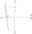
- Figure 10 illustrates a relationship diagram of the voltage vs. the power for two wind turbines having different reactive power set points in accordance with the present disclosure.
- V virt a correction factor 188 (V virt ) based on the measured reactive power 164 (Q g_fbk ) and the voltage droop signal (K droop ) is added to modify the voltage instructions 170 of the two wind turbines, keeping the two wind turbines at the same measured terminal voltage V g .
Landscapes
- Engineering & Computer Science (AREA)
- Power Engineering (AREA)
- Control Of Eletrric Generators (AREA)
- Selective Calling Equipment (AREA)
- Physics & Mathematics (AREA)
- General Physics & Mathematics (AREA)
- Automation & Control Theory (AREA)
- Life Sciences & Earth Sciences (AREA)
- Sustainable Development (AREA)
- Sustainable Energy (AREA)
Abstract
Description
- The present application relates to wind turbines and, more particularly, to systems and methods particularly for providing stability voltages to a plurality of wind turbines connected to a power grid.
- Wind power is considered one of the cleanest, most environmentally friendly energy sources presently available, and wind turbines have gained increased attention based on this reason. A modern wind turbine typically includes a tower, generator, gearbox, engine room, and one or more rotor blades. The rotor blades capture kinetic energy of wind using known airfoil principles. For example, rotor blades typically have the cross-sectional profile of an airfoil such that air flows over the blade producing a pressure difference between the sides during operation. Consequently, a lift force, which is directed from a pressure side towards a suction side, acts on the blade. The lift force generates the torque on the main rotor shaft, which is driven to a generator for producing electricity.
- For example,
Figures 1 and2 illustrate a conventionally constructedwind turbine 10 and an associated power system suitable for use with thewind turbine 10. As shown, thewind turbine 10 includes anengine room 14 that typically houses a generator 28 (Fig. 2 ). Theengine room 14 is mounted on atower 12 that extends from a support surface (not shown). Thewind turbine 10 also includes arotor 16 that includes a plurality ofrotor blades 20 attached to a rotatinghub 18. When the wind impacts therotor blade 20, theblade 20 converts the kinetic energy of the wind into a mechanical rotational torque that rotatably drives alow speed shaft 22. Thelow speed shaft 22 is structured to drive a gearbox 24 (if present), which then raises the low rotational speed of thelow speed shaft 22 to drive ahigh speed shaft 26 at an increased rotational speed. Thehigh speed shaft 26 is typically rotatably connected to a generator 28 (e.g., a doubly-fed induction generator, or DFIG) to rotatably drive a generator rotor 30. Thus, the generator rotor 30 can induce a rotating magnetic field. A voltage can be induced within agenerator stator 32, which is magnetically coupled to the generator rotor 30. The associated power can be transmitted from thegenerator stator 32 to a three-winding transformer 34, which is typically connected to a power grid through agrid breaker 36. Therefore, the main transformer 34 raises the voltage amplitude of the power so that the converted power can be further transmitted to the power grid. - Moreover, as shown, the
generator 28 is typically electrically coupled to abi-directional power converter 38 that includes arotor side converter 40 that is connected to a line side converter 42 through a regulated DC link 44. Therotor side converter 40 converts the AC power supplied from the rotor 30 into the DC power and supplies the DC power to the DC link 44. The Line side converter 42 converts the DC power on DC link 44 into AC output power suitable for the power grid. Thus, the AC power frompower converter 38 can be combined with power from thestator 32 to provide multi-phase power (e.g., three-phase power) having a frequency that is substantially maintained at the grid frequency (e.g., 50 Hz / 60 Hz). - The shown three-winding transformer 34 typically has (1) a 33 kV medium voltage (MV) primary winding 33 connected to the power grid, (2) a 6 to 13.8 kV MV secondary winding 35 connected to the
generator stator 32, and (3) a 690 to 900 volt (V) low voltage (LV)third winding 37 connected to the line side converter 42. - With the increasing success of wind power production in recent years, this form of power has gained a significant market share. As shown in
FIG. 3 , separate power systems having a plurality ofwind turbines 10 can be disposed at predetermined geologic locations and electrically connected together to form awind farm 46. More specifically, as shown, thewind turbines 10 can be arranged into a plurality ofgroups 48, each group being connected to a main line 50 throughswitches wind turbine group 48 prior to transmitting power to the grid. Since wind energy is not a power source with a constant power output, but with some variations, e.g. variations due to wind speed, operators of distribution networks must take this into account. The three-winding transformer 34 of thewind turbine 10 contributes to the stable operation of the turbine. - However, the three-winding transformer 34 associated with each
wind turbine 10 is expensive. In particular, for megawatt (MW) wind turbines, full rated transformer increases the total cost and loss of the wind farm. - Accordingly, it is desirable to provide a control system or control method for a power system to addresses one or more of the above condition.
- Aspects and advantages of the present disclosure will be set forth in part in the following description, or may be obvious from the description, or may be learned through practice of the present disclosure.
- In one embodiment of the present application, a method for controlling a power system connected to a power grid is disclosed. The power system has a plurality of power subsystem clusters, each of the power subsystems including a generator and defining a stator power path and a converter power path for supplying power to the power grid, the converter power path having a partial power transformer and a rotor power path. The method comprises: receiving, by a controller, a reactive power instruction and a measured reactive power from the generator; generating a reactive power error signal by the controller based on a difference between the reactive power instruction and the measured reactive power; receiving the reactive power error signal by a reactive power regulator; generating a voltage instruction by the reactive power regulator based on the reactive power error signal; generating a voltage droop signal by a droop controller based on a reference reactance and a voltage at a point of common coupling; generating, by the controller, the voltage error signal according to at least one of the voltage instruction or a measured terminal voltage of the generator and the voltage droop signal; and generating a reactive current instruction for the converter power path by the voltage regulator based on the voltage error signal.
- In another embodiment of the present application, a control system for a power system connected to a power grid is disclosed. The power system has a plurality of power subsystem clusters, each of the power subsystems including a generator and defining a stator power path and a converter power path for supplying power to the power grid, the converter power path having a partial power transformer and a rotor power path. The control system comprises: one or more sensors for generating at least one of a measured reactive power or a measured terminal voltage from the generator; a controller configured to receive a reactive power instruction and the measured reactive power from the generator, and generate a reactive power error signal based on a difference between the reactive power instruction and the measured reactive power; a reactive power regulator configured to receive the reactive power error signal and generates a voltage instruction based on the reactive power error signal; a droop controller configured to generate a voltage droop signal based on a reference reactance and a voltage at a point of common coupling; the controller is further configured to generate a voltage error signal according to at least one of the voltage instruction or the measured terminal voltage of the generator and the voltage droop signal; a voltage regulator, configured to generate a reactive current instruction based on the voltage error signal.
- In yet another embodiment of the present application, a wind farm is disclosed, comprising: a plurality of wind turbine clusters, a cluster transformer and a plurality of turbine controllers. Wherein each of the wind turbine clusters comprises a plurality of wind turbines, each of the wind turbines having a power converter electrically coupled to a generator having a generator rotor and a generator stator. Each of the wind turbines defines a stator power path and a converter power path for supplying power to the power grid, the converter power path including a partial power transformer. The cluster transformer connects each of the wind turbine groups to the power grid. each of the turbine controllers communicatively coupled to one of the wind turbines, the turbine controller configured to perform one or more operations comprising: receiving a reactive power instruction and a measured reactive power from the generator; generating a reactive power error signal based on a difference between the reactive power instruction and the measured reactive power; receiving the reactive power error signal; generating a voltage instruction based on the reactive power error signal; generating a voltage droop signal based on a reference reactance and a voltage at a point of common coupling; generating a voltage error signal according to at least one of the voltage instruction or a measured terminal voltage of the generator and the voltage droop signal; generating a reactive current instruction for the converter power path based on the voltage error signal.
- These and other features, aspects and advantages of the present disclosure will become better understood with reference to the following description and appended claims. The accompanying drawings, which are incorporated into and constitute a part of this description, illustrate the present disclosure and, together with the description, further serve to explain the principles of the present disclosure.
- A complete and feasible disclosure of the present disclosure, including the best mode thereof, is set forth in the description for those of ordinary skill in the art with reference to the accompanying drawings, in which:
-
FIG. 1 illustrates a perspective view of a portion of one embodiment of a wind turbine in accordance with the conventional structure. -
FIG. 2 illustrates a schematic diagram of a conventional power system suitable for the wind turbine shown inFigure 1 . -
FIG. 3 illustrates a schematic diagram of one embodiment of a conventional wind farm in accordance with conventional structure, particularly illustrates a plurality of wind turbine power systems as shown inFIG. 1 connecting to a single substation transformer. -
FIG. 4 illustrates a schematic diagram of one embodiment of a power system for a wind turbine in accordance with the present disclosure. -
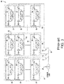
FIG. 5 illustrates a schematic diagram of one embodiment of a wind farm in accordance with the present disclosure, particularly illustrates a plurality of wind turbine groups, each of which connected to a power grid by a cluster transformer. -
FIG. 6 illustrates a block diagram of one embodiment of a wind turbine controller in accordance with the present disclosure. -
FIG. 7 illustrates a schematic diagram of one embodiment of a control system in accordance with the present disclosure. -
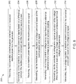
FIG. 8 illustrates a flow chart of one embodiment of a method for controlling a power system connected to a power grid in accordance with the present disclosure. -
FIG. 9 illustrates a relationship diagram of the voltage vs. reactive power for two wind turbines having same reactive power set points in accordance with the present disclosure. And -
Figure 10 illustrates a relationship diagram of the voltage vs. power for two wind turbines having different reactive power set points in accordance with the present disclosure. - Reference now will be made in detail to embodiments of the invention. One or more examples of the present disclosure are illustrated in the drawings. Each example is provided by way of explanation of the invention rather than the limitation of the invention. In fact, it will be apparent to those skilled in the art that various modifications and variations can be made in the present disclosure without departing from the scope or spirit of the present disclosure. For instance, features illustrated or described as a part of one embodiment can be used with another embodiment to yield a still further embodiment. Thus, it is intended that the present disclosure covers such modifications and variations and their equivalents as within the scope of the appended claims.
- Generally, the present disclosure relates to a method for controlling a power system connected to a power grid. The method includes receiving a reactive power instruction and a measured reactive power from a generator, and generating a reactive power error signal based on a difference between the reactive power instruction and the measured reactive power. Additionally, the method includes receiving a reactive power error signal and generating a voltage instruction based on the reactive power error signal. The method also includes generating a voltage droop signal based on a reference reactance and a voltage at a point of common coupling. As such, the method further includes generating a voltage error signal according to at least one of the voltage instruction or the measured terminal voltage of the generator and the voltage droop signal, and generating a reactive current instruction of the converter power path based on the voltage error signal.
- The present disclosure provides many advantages that are not present in the prior art. For example, the present disclosure reduces reactive power oscillations or the transient voltage instability between wind turbines due to low impedance between each turbine generator. In some embodiments, the power system does not include a three-winding transformer or a pedestal-mounted transformer (PMT).
- Referring now to
Figure 4 , a schematic diagram of one embodiment of apower subsystem 102 in accordance with the present disclosure is shown. It should be understood that the term "subsystem" is used herein to distinguish various power systems (e.g., as shown inFigure 4 ) and theentire power system 105 ofFigure 5 . However, one of Ordinary Skill in the Art will recognize that thepower subsystem 102 ofFIG. 4 can also be referred to in more general terms, for example only a system (rather than a subsystem). Therefore, these terms may be used interchangeably and are not meant to be limiting. - Moreover, as shown, the
power subsystem 102 may correspond to a windturbine power system 100. More specifically, as shown, the windturbine power system 100 includes arotor 104 that includes a plurality ofrotor blades 106 attached to a rotating hub. When the wind impacts therotor blade 106, theblade 106 converts the wind energy into a mechanical rotational torque that rotatably drives alow speed shaft 110. Thelow speed shaft 110 is configured to drive agearbox 112, and then raises the low speed of alow speed shaft 110 to drive ahigh speed shaft 114 to rotate at an increased speed. Thehigh speed shaft 114 is typically rotatably coupled to a doubly-fed induction generator 116 (hereinafter referred to as DFIG 116) to rotatably drive agenerator rotor 118. As such, the generator rotor can induce a rotating magnetic field. In one embodiment, for example, thegenerator 116 is configured to convert the rotational mechanical energy into a sinusoidal three-phase alternating current (AC) power signal in thegenerator stator 120. Thus, as shown, the associated power can be transmitted directly from thegenerator stator 120 to the power grid. - Additionally, as shown, the
generator 116 is electrically coupled to abi-directional power converter 122 including a rotor-side converter 124 connected to aline side converter 126 through aregulated DC link 128. Therefore, therotor side converter 124 converts the AC power supplied by thegenerator rotor 118 into the DC power and supplies the DC power to theDC link 128. TheLine side converter 126 converts the DC power on thelink 128 into the AC output power suitable for the power grid. More specifically, as shown, the AC power from thepower converter 122 may be combined with power from thegenerator stator 120 via aconverter power path 127 and astator power path 125, respectively. For example, as shown, and in contrast to those conventional systems as shown inFIGS. 1-3 , theconverter power path 127 may include apartial power transformer 130 for raising the voltage amplitude of power from thepower converter 122, so that the converted power can be further transmitted to the power grid. Thus, as shown, thesystem 102 shown inFigure 4 does not include the conventional three-winding transformer described above. To some extent, in the illustrated embodiment, apartial power transformer 130 may correspond to a two-winding transformer having a primary winding 132 connected to the power grid and a secondary winding 134 connected to therotor side converter 124. In some embodiments, the dual winding transformer is a three phase transformer. Since there is no leakage impedance of the transformer in the stator power path, therotor side converter 124 is modified to achieve a smooth response on different windturbine power systems 100. - Moreover, the
power system 100 can include one or more controllers. For example, as shown inFIG. 6 , thesystem 100 can include a system level controller (e.g. the farm level controller 107), one or morecluster level controllers 156, and/or one or more subsystem level controllers (e.g. the turbine level controller 136). As such, the various controllers described herein are configured to control any of the components of thewind farm 105, thewind turbine group 137, and/or the individual windturbine power system 100, and/or implement method steps as described herein. - For example, as specifically shown in
Figure 6 is a block diagram of one embodiment of a controller as described herein. As shown, the controller can include one ormore processors 138 and associatedmemory devices 140 that are configured to execute various computer-implemented functions (e.g. as disclosed herein, executing related operations such as methods, steps, calculations etc., and storing related data). Additionally, the controller may also include acommunication module 142 to facilitate communication between the controller and various components of thewind farm 105, for example, any components inFig 4 and5 . Moreover, thecommunication module 142 may include a sensor interface 144 (e.g., one or more analog-to-digital converters) to allow signals transmitted from one ormore sensors processor 138. It should be understood that thesensors communication module 142 using any suitable devices. For example, as shown inFIG. 6 , thesensors sensor interface 144 by a wired connection. However, in other embodiments, thesensors sensor interface 144 via a wireless connection, for example, using any suitable wireless communication protocol known in the art. As such, theprocessor 138 can be configured to receive one or more signals from thesensors - As used herein, the term "processor" refers not only to an integrated circuit as indicated in the art as included in a computer, but also to a controller, a microcontroller, a microcomputer, a programmable logic controller (PLC), an application specific integrated circuit and other programmable circuits. The
processor 138 is also configured to calculate advanced control algorithms and to communicate various Ethernet or serial based protocols (Modbus, OPC, CAN, etc.). Additionally, one ormore memory devices 140 may generally comprise one or more memory elements including, but not limited to, computer readable media (e.g., random access memory (RAM)), computer readable nonvolatile media (e.g., flash memory), floppy disk, compact disk read only memory (CD-ROM), magneto-optical disk (MOD), digital versatile disk (DVD), and/or other suitable memory elements. This or these memory device(s) 140 may be generally configured to store suitable computer readable instructions that, when implemented by one ormore processors 138, configure the controller to perform various functions as described herein. - In operation, alternating current (AC) power generated at the
generator stator 120 by rotation of therotor 104 is supplied to the power grid via dual path, i.e., via thestator power path 125 and theconverter power path 127. More specifically, therotor side converter 124 converts the AC power supplied from thegenerator rotor 118 into the DC power and supplies the DC power to theDC link 128. The switching elements (eg, IGBTs) used in the bridge circuit of therotor side converter 124 can be modulated to convert the AC power provided from thegenerator rotor 118 to the DC power suitable for theDC link 124. Theline side converter 126 converts the DC power on the DC link 128 into AC output power suitable for the power grid. In particular, switching elements (e.g., IGBTs) used in the bridge circuit ofline side converter 126 can be modulated to convert the DC power on the DC link 128 to the AC power. Thus, the AC power from thepower converter 122 can be combined with power from thegenerator stator 120 to provide multi-phase power having a frequency that is substantially maintained at the bus frequency. It should be understood that therotor side converter 124 and theline side converter 126 can have any configuration to facilitate operation of any switching devices of thepower system 200 as described herein. - Moreover, the
power converter 122 can be in electronic data communication with aturbine controller 136 and/or a separate orintegral conversion controller 154 to control operation of therotor side converter 124 and theline side converter 126. For example, during operation, thecontroller 136 can be configured to receive one or more voltage and/or current measurement signals from a first set of voltage andcurrent sensors controller 136 can be configured to monitor and control at least some of the operational variables associated with windturbine power system 100 by thesensors sensors power subsystem 102 to facilitate operation of thepower subsystem 102 as described herein. - It should also be understood that any number or type of voltage and/or current sensors can be employed within the wind
turbine power system 100 and at any location. For example, the sensor can be a current transformer, a shunt sensor, a Rogowski coil, a Hall effect current sensor, a micro inertial measurement unit (MIMU) or the like, and/or any other suitable voltage or current sensor known at this stage or later developed. Accordingly, theconversion controller 154 is configured to receive one or more voltage and/or current feedback signals from thesensors - As shown in
FIG. 5 , various power systems (e.g.,power subsystem 102 shown inFIG. 4 ) may be arranged in at least twoclusters 137 to form apower system 105. More specifically, as shown, the windturbine power system 100 can be arranged.Multiple clusters 137 are accessed to form a wind farm. Thus, as shown, eachcluster 137 can be connected toseparate transformers switches cluster 137 such that the transformed power can be further transmitted to the power grid. Additionally, as shown, thetransformers main line 148, which combines the voltage from eachcluster 137 before sending power to the power grid. Moreover, as described above, eachcluster 137 can be communicatively coupled to thecluster level controller 156. - However, due to the lack of the impedance provided by the secondary windings 35 in the main three-winding transformers 34 of conventional systems, it becomes difficult for each wind turbine to regulate its terminal voltage. More specifically, such systems (systems as shown in
Figure 4 ) are known to experience reactive power oscillations. Thus,FIG. 7 illustrates a schematic diagram of one embodiment of acontrol system 160 in accordance with the present disclosure that addresses the problems associated with that resulting from the removal of the main transformer 34 shown inFIG 2 . - As shown, a
control system 160 includes two loops: avoltage regulator loop 192 and a reactive power (Q)regulator loop 190. Thevoltage regulator loop 192 operates relatively faster (e.g., 20 rad/sec) compared to the Q regulator loop 190 (e.g., a closed loop time constant greater than 1 second). Moreover, a reactive power (VAR)regulator 168 regulates the set point of thevoltage regulator loop 192. Conceptually, the control system ofFig 7 provides terminal voltage control of the wind turbine generator by regulating the voltage to a reference point set by the controller. The reactive power is regulated for a longer period of time (e.g., a few seconds) while the terminal voltage of the wind turbine generator is regulated for a shorter period of time (e.g., less than a few seconds) to mitigate the effects of rapid grid transients. - More specifically, as shown, a reactive power instruction 162 (Qg_cmd) of the
generator 116, which corresponds to a instruction indicating the target reactive power generated by thegenerator 116, is compared to a signal indicating the measured reactive power (Qg_fbk). The resulting reactive power error signal 166 represents the difference between the measuredreactive power 164 and the indicated reactive power 162. The reactive power error signal 166 is an input signal of thereactive power regulator 168, which produces a voltage instruction 170 (Vg_cmd) for indicating the reactive power provided by thegenerator 116. - In some embodiments, the
voltage instruction 170 is limited to a predetermined range, for example, by alimiter 172, and then compared to the signal of a terminal voltage 174 (Vg_fbk) measured by thegenerator 116. Moreover, as shown, thecontrol system 160 also includes adroop controller 186 for generating a voltage droop signal 188 (Kdroop) based on a reference reactance and a voltage at a point of common coupling. As such, thedroop controller 186 allows the wind turbines to operate in parallel without creating mutual control effect and power oscillations there between by providing droop control for each turbine in the wind farm. - In some embodiments, this limitation is determined by some fixed parameter discussion, however, this limitation may also be provided, for example, by a lookup table or dynamically variable parameters provided by a processor/state machine executing a control algorithm. This dynamic variable limit can be obtained based on the current rating of the generator and the synchronized actual power output.
- With further reference to
FIG. 7 , avoltage error signal 176, which is the input signal to avoltage regulator 178, is generated according to at least one of thevoltage instruction 170 or the measuredterminal voltage 174 of the generator and thevoltage droop signal 188. - Subsequently,
voltage regulator 178 generates a reactive current instruction 180 (ly_cmd) for the converter power path. In some embodiments, thevoltage regulator 178 is a proportional-integral (PI) controller with a closed-loop time constant of approximately 50 milliseconds. Other types of controllers can also be used, for example proportional differential (PD) controllers, proportional integral differential (PID) controllers, or state space controllers etc. For thevoltage regulator 178, other time constants (e.g., 1 second, 20 milliseconds, 75 milliseconds, 45 milliseconds) may be used provided that the time constant of thetime voltage regulator 178 is less than the time constant of thereactive power regulator 168. Typically, the reactivecurrent instruction 180 has two components, i.e. an active power component and a reactive power component. For example, the reactivecurrent instruction 180 generated as described inFigure 7 is a reactive power component instruction. The active power component can be generated in any manner known in the art. In some embodiments, thecontrol system 160 also receives the reactivecurrent instruction 180 and generates areactive voltage instruction 182 for theline side converter 126 and therotor side converter 124. - Referring to
Figure 8 , a flow diagram of one embodiment of amethod 200 for a power system (as shown inFigure 5 ) connected to a power grid is shown in accordance with the present disclosure. As shown at 202, themethod 200 includes receiving, by a controller, a reactive power instruction 162 and a measured reactive power 164 (Qg_fbk). As shown at 204, themethod 200 includes generating a reactive power error signal 166 by the controller based on the difference between the reactive power instruction 162 and the measured reactive power 164 (Qg_fbk). As shown at 206,method 200 includes receiving a reactive power error signal 166 by areactive power regulator 168. As shown at 208, themethod 200 includes generating a voltage instruction (i.e., voltage instruction 170) by thereactive power regulator 168 based on the reactive power error signal 166. - As shown at 210, the
method 200 includes generating avoltage droop signal 188 by adroop controller 186 based on a reference reactance and a voltage at a point of common coupling. As shown at 212, avoltage error signal 176 is generated by the controller based on at least one of avoltage instruction 170 or a measured terminal voltage 174 (Vg_fbk) of the generator and thevoltage droop signal 188. More specifically, in one embodiment, the controller can generate thevoltage error signal 176 using the equation (1) below. For example, as shown, the controller can generate avoltage error signal 176 by: subtracting the measured terminal voltage 174 (Vg_fbk) from the voltage instruction 170 (Vg_cmd) to obtain a first value; then, the controller can multiply the measured reactive power (Qg_fbk) by the voltage droop signal 188 (Kdroop) to obtain a second value; then, the controller can subtract the second value from the first value to obtain thevoltage error signal 176 as shown below.
- As shown at 214, the
method 200 includes generating the reactive current instruction 180 (ly_cmd) by a voltage regulator based on thevoltage error signal 176. More specifically, the reactive current instruction can be calculated using Equation (2) below.
- In some embodiments, a method is disclosed to simulate a virtual impedance drop by obtaining an appropriate
voltage droop signal 188 to maintain the voltage stability of the system and the minimization of reactive power oscillations. The method of obtaining thevoltage droop signal 188 is as follows. - In a traditional PMT (or three-winding transformer) topology, the reactive current instruction of a DFIG converter can be expressed as:


- In the PMT-free topology, see
Figures 7 and8 , because there is no leakage impedance of the PMT in the system,the reactive current instruction can be calculated using equation (2). Combining the equation (5) with the equation (2), thevoltage droop signal 188 can be derived by the equation (6):
- In some embodiments, in a PMT-free topology, the voltage at the point of common coupling (Vg_pocc) is substantially equal to the measured terminal voltage (Vg_fbk) of the generator. The
voltage droop signal 188 can be calculated using equation (7) below. The voltage droop signal 188 (Kdroop) is obtained by the reference reactance (Xxf) and the voltage at the point of common coupling (Vg_pocc), where the reference reactance can be the reactance of a virtual pedestal mounted transformer (PMT) used in conventional power systems. In this embodiment, the voltage droop signal 188 (Kdroop) is obtained by dividing the reactance of the virtual pad mounted transformer (Xxf) by the voltage at the point of common coupling (Vg_pocc).
- In some embodiments, the predetermined range of the limiter 172 (shown in
Figure 7 ) is generated according to the voltage droop signal 188 (Kdroop). More specifically, generating the predetermined range according to the voltage droop signal 188 (Kdroop) comprises: adding thevoltage droop signal 188 to the maximum value of the original voltage range to obtain the maximum value of the predetermined range; and subtracting the voltage droop signal 188 from the minimum value of the original voltage range to obtain the minimum value of the predetermined range. -
FIG. 9 illustrates a relationship diagram of the voltage vs. the reactive power for two wind turbines having the same reactive power set points in accordance with the present disclosure. The set points of the voltage regulators on the two wind turbines are the same at the sampling operating point, and the reactive power instructions Q1, Q2 and the voltage instructions Vg1, Vg2 of the two generators are also substantially the same, so the droop control may not be activated. However,Figure 10 illustrates a relationship diagram of the voltage vs. the power for two wind turbines having different reactive power set points in accordance with the present disclosure. When the reactive power instructions Q1', Q2' are different, a correction factor 188 (Vvirt) based on the measured reactive power 164 (Qg_fbk) and the voltage droop signal (Kdroop) is added to modify thevoltage instructions 170 of the two wind turbines, keeping the two wind turbines at the same measured terminal voltage Vg. - This written description uses examples including the best mode to disclose the invention, and also to enable any person skilled in the art to practice the invention, including making and using any devices or systems and performing any incorporated methods. The patentable scope of the present disclosure is defined by the claims, and may include other examples that occur to those skilled in the art. Such other examples are intended to be within the scope of the claims if they include structural elements that do not differ from the literal language of the claims, or if they include equivalent structural elements with insubstantial differences from the literal languages of the claims.
Claims (20)
- A method for controlling a power system connected to a power grid, the power system having a plurality of power subsystem clusters, each of the power subsystems including a generator and defining a stator power path and a converter power path for supplying power to the power grid, the converter power path having a partial power transformer and a rotor power path, the method comprising:receiving, by a controller, a reactive power instruction and a measured reactive power from the generator;generating a reactive power error signal by the controller based on a difference between the reactive power instruction and the measured reactive power;receiving the reactive power error signal by a reactive power regulator;generating a voltage instruction by the reactive power regulator based on the reactive power error signal;generating a voltage droop signal by a droop controller based on a reference reactance and a voltage at a point of common coupling;generating, by the controller, the voltage error signal according to at least one of the voltage instruction or a measured terminal voltage of the generator and the voltage droop signal; andgenerating a reactive current instruction for the converter power path by the voltage regulator based on the voltage error signal.
- The method of claim 1, wherein the reference reactance is a reactance of a virtual pedestal mounted transformer.
- The method of claim 1, wherein the voltage at the point of common coupling is substantially equal to the measured terminal voltage of the generator.
- The method of claim 1, further comprising one predetermined range generated according to the voltage droop signal, wherein the predetermined range is used for limiting the voltage instruction.
- The method of claim 4, wherein generating the predetermined range according to the voltage drop signal comprises:adding the voltage droop signal to a maximum value of an original voltage range to obtain a maximum value of the predetermined range; andsubtracting the voltage droop signal from a minimum value of an original voltage range to obtain a minimum value of the predetermined range.
- The method of claim 1, further comprising: generating a reactive voltage instruction of the converter power path by the controller based on the reactive current instruction.
- The method of claim 6, further comprising: converting AC power from the generator to reactive DC power by a switching element of the rotor power path based on the reactive voltage instruction.
- The method of claim 1, wherein the voltage error signal generated by the controller according to at least one of the voltage instruction or the measured terminal voltage of the generator and the voltage droop signal, comprising:subtracting the measured terminal voltage from the voltage instruction to obtain a first value;multiplying the measured reactive power by the voltage droop signal to obtain a second value; andsubtracting the second value from the first value to obtain the voltage error signal.
- The method of claim 1, wherein one of the reactive power regulator and the voltage regulator comprises at least one of a proportional integral (PI) controller, a proportional differential (PD) controller, a proportional integral differential (PID) controller, and one state space controller.
- The method of claim 1, wherein the generator of each of the power subsystems comprises a doubly-fed induction generator (DFIG).
- A control system for a power system connected to a power grid, the power system having a plurality of power subsystem clusters, each of the power subsystems including a generator and defining a stator power path and a converter power path for supplying power to the power grid, the converter power path having a partial power transformer and a rotor power path, the control system comprising:one or more sensors for generating at least one of measured reactive power or measured terminal voltage from the generator;a controller configured to receive a reactive power instruction and the measured reactive power from the generator, and generate reactive power error signal based on a difference between the reactive power instruction and the measured reactive power;a reactive power regulator configured to receive the reactive power error signal and generates a voltage instruction based on the reactive power error signal;a droop controller configured to generate a voltage droop signal based on a reference reactance and a voltage at a point of common coupling;the controller is further configured to generate a voltage error signal according to at least one of the voltage instruction or the measured terminal voltage of the generator and the voltage droop signal; anda voltage regulator configured to generate a reactive current instruction based on the voltage error signal.
- The control system of claim 11, wherein the voltage at the point of common coupling is substantially equal to the measured terminal voltage of the generator.
- The control system of claim 11, further comprising a limiter configured to generating one predetermined range generated according to the voltage droop signal, wherein the predetermined range is used for limiting the voltage instruction.
- The control system of claim 13, wherein the limiter generates the predetermined range according to the voltage drop signal by:adding the voltage droop signal to a maximum value of an original voltage range to obtain a maximum value of the predetermined range; andsubtracting the voltage droop signal from a minimum value of an original voltage range to obtain a minimum value of the predetermined range.
- The control system of claim 11, wherein the voltage error signal generated by the controller according to at least one of voltage instruction or measured terminal voltage of the generator and the voltage droop signal by:subtracting the measured terminal voltage from the voltage instruction to obtain a first value;multiplying the measured reactive power by the voltage droop signal to obtain a second value; andsubtracting the second value from the first value to obtain the voltage error signal.
- The control system of claim 11, wherein the reactive power regulator comprises at least one of a proportional integral (PI) controller, a proportional differential (PD) controller, a proportional integral differential (PID) controller, or state space controller.
- The control system of claim 11, wherein the power system comprises a wind farm, wherein the power subsystem comprises a wind turbine power system.
- A wind farm that includes:a plurality of wind turbine clusters, each of the wind turbine clusters comprising a plurality of wind turbines, each of the wind turbines having a power converter electrically coupled to a generator having a generator rotor and a generator stator, each of the wind turbines defining a stator power path and a converter power path for supplying power to the power grid, the converter power path including a partial power transformer;a cluster transformer, connecting each of the wind turbine groups to the power grid; anda plurality of turbine controllers, each of the turbine controllers communicatively coupled to one of the wind turbines, the turbine controller configured to perform one or more operations, the one or more operations comprising:receiving a reactive power instruction and a measured reactive power from the generator;generating a reactive power error signal based on a difference between the reactive power instruction and the measured reactive power;receiving the reactive power error signal;generating a voltage instruction based on the reactive power error signal;generating a voltage droop signal based on a reference reactance and a voltage at a point of common coupling;generating the voltage error signal according to at least one of the voltage instruction or a measured terminal voltage of the generator and the voltage droop signal; andgenerating a reactive current instruction for the converter power path based on the voltage error signal.
- The wind farm of claim 18, wherein a predetermined range generated according to the voltage droop signal is used to limit the voltage instruction, wherein generating the predetermined range comprising:adding the voltage droop signal to a maximum value of an original voltage range to obtain a maximum value of the predetermined range; andsubtracting the voltage droop signal from a minimum value of an original voltage range to obtain a minimum value of the predetermined range.
- The wind farm of claim 18, wherein the voltage error signal generated according to at least one of voltage instruction or measured terminal voltage of the generator and the voltage droop signal, comprising:subtracting the measured terminal voltage from the voltage instruction to obtain a first value;multiplying the measured reactive power by the voltage droop signal to obtain a second value; andsubtracting the second value from the first value to obtain the voltage error signal.
Applications Claiming Priority (1)
| Application Number | Priority Date | Filing Date | Title |
|---|---|---|---|
| CN201810832993.7A CN110768308B (en) | 2018-07-26 | 2018-07-26 | A system and method for controlling a power system connected to a grid |
Publications (2)
| Publication Number | Publication Date |
|---|---|
| EP3614520A1 true EP3614520A1 (en) | 2020-02-26 |
| EP3614520B1 EP3614520B1 (en) | 2023-06-07 |
Family
ID=67439120
Family Applications (1)
| Application Number | Title | Priority Date | Filing Date |
|---|---|---|---|
| EP19188661.3A Active EP3614520B1 (en) | 2018-07-26 | 2019-07-26 | Systems and methods for controlling electrical power systems connected to a power grid |
Country Status (5)
| Country | Link |
|---|---|
| US (1) | US11637515B2 (en) |
| EP (1) | EP3614520B1 (en) |
| CN (1) | CN110768308B (en) |
| ES (1) | ES2954465T3 (en) |
| PL (1) | PL3614520T3 (en) |
Families Citing this family (4)
| Publication number | Priority date | Publication date | Assignee | Title |
|---|---|---|---|---|
| US10826297B2 (en) * | 2018-11-06 | 2020-11-03 | General Electric Company | System and method for wind power generation and transmission in electrical power systems |
| FI129136B (en) * | 2019-10-30 | 2021-08-13 | Wattium Oy | ELECTRICITY GENERATION SYSTEM AND METHOD |
| US11177660B2 (en) * | 2020-01-27 | 2021-11-16 | Mitsubishi Electric Power Products, Inc. | System and method for power converter control for virtual impedance |
| AU2021401121A1 (en) * | 2020-12-18 | 2023-08-03 | Vestas Wind Systems A/S | Improvements in or relating to voltage control in renewable energy power plants |
Citations (3)
| Publication number | Priority date | Publication date | Assignee | Title |
|---|---|---|---|---|
| US20150061290A1 (en) * | 2013-09-05 | 2015-03-05 | General Electric Company | System and method for voltage control of wind generators |
| US20160259399A1 (en) * | 2015-03-06 | 2016-09-08 | National Tsing Hua University | Consensus-based power control apparatus |
| CN107834564A (en) * | 2017-11-02 | 2018-03-23 | 上海电力学院 | A kind of control method of the Small disturbance voltage stability of micro-grid system |
Family Cites Families (9)
| Publication number | Priority date | Publication date | Assignee | Title |
|---|---|---|---|---|
| JP4269941B2 (en) * | 2004-01-08 | 2009-05-27 | 株式会社日立製作所 | Wind power generator and control method thereof |
| JP3918837B2 (en) * | 2004-08-06 | 2007-05-23 | 株式会社日立製作所 | Wind power generator |
| US9371821B2 (en) * | 2012-08-31 | 2016-06-21 | General Electric Company | Voltage control for wind turbine generators |
| EP2904684B1 (en) * | 2012-10-08 | 2024-06-12 | Vestas Wind Systems A/S | Controller and method for line reactance compensation |
| CN103078349B (en) * | 2013-01-17 | 2016-07-20 | 河海大学 | A kind of double-fed wind power generator system and low voltage traversing control method |
| CN103414207A (en) * | 2013-07-15 | 2013-11-27 | 中国科学院电工研究所 | Droop control-based smooth switching method |
| DE102014214151A1 (en) * | 2014-07-21 | 2016-01-21 | Siemens Aktiengesellschaft | A multi-generator power plant assembly, power grid having a multi-generator power plant arrangement, and method of distributing reactive power generation in a multi-generator power plant arrangement |
| CN105811394B (en) * | 2014-12-30 | 2019-03-08 | 国家电网公司 | A Voltage Estimation Method for Approximate Calculation of Power Flow in Power System |
| CN105226716B (en) * | 2015-11-04 | 2017-07-21 | 浙江运达风电股份有限公司 | A kind of distributed double-fed wind power generator group automatic voltage control method |
-
2018
- 2018-07-26 CN CN201810832993.7A patent/CN110768308B/en active Active
-
2019
- 2019-07-26 EP EP19188661.3A patent/EP3614520B1/en active Active
- 2019-07-26 ES ES19188661T patent/ES2954465T3/en active Active
- 2019-07-26 US US16/523,432 patent/US11637515B2/en active Active
- 2019-07-26 PL PL19188661.3T patent/PL3614520T3/en unknown
Patent Citations (3)
| Publication number | Priority date | Publication date | Assignee | Title |
|---|---|---|---|---|
| US20150061290A1 (en) * | 2013-09-05 | 2015-03-05 | General Electric Company | System and method for voltage control of wind generators |
| US20160259399A1 (en) * | 2015-03-06 | 2016-09-08 | National Tsing Hua University | Consensus-based power control apparatus |
| CN107834564A (en) * | 2017-11-02 | 2018-03-23 | 上海电力学院 | A kind of control method of the Small disturbance voltage stability of micro-grid system |
Also Published As
| Publication number | Publication date |
|---|---|
| EP3614520B1 (en) | 2023-06-07 |
| CN110768308B (en) | 2023-07-18 |
| ES2954465T3 (en) | 2023-11-22 |
| PL3614520T3 (en) | 2023-09-11 |
| US11637515B2 (en) | 2023-04-25 |
| CN110768308A (en) | 2020-02-07 |
| US20200052493A1 (en) | 2020-02-13 |
Similar Documents
| Publication | Publication Date | Title |
|---|---|---|
| US10951030B2 (en) | System and method for reactive power control of a wind farm | |
| CN109995093A (en) | The dynamic of wind power plant is active and reactive power capacity | |
| AU2009338570A1 (en) | Power system frequency inertia for power generation system | |
| CN103683301B (en) | voltage control system and method for wind-driven generator | |
| EP3614520B1 (en) | Systems and methods for controlling electrical power systems connected to a power grid | |
| CN114930711A (en) | System and method for providing grid formation control for doubly-fed wind turbine generators | |
| CN114597935A (en) | Method of controlling negative sequence currents for grid formation control of inverter-based resources | |
| CN111602307B (en) | System and method for optimizing reactive power generation of a wind farm | |
| CN111316521B (en) | System and method for controlling an electric power system connected to an electric power grid | |
| CN116526585A (en) | System and method for providing grid shaping control of inverter-based resources | |
| CN109424502B (en) | System and method for preventing voltage collapse of wind turbine power system | |
| US10218298B2 (en) | Spillover of reactive current to line side converter | |
| CN114977268A (en) | System and method for providing grid formation control for doubly fed wind turbine generators | |
| EP3639341B1 (en) | Electrical power subsystems and methods for controlling same | |
| EP4175105B1 (en) | System and method for reducing instability in reactive power command of an inverter-based resource | |
| US10886726B2 (en) | Control method for protecting transformers | |
| US20220364543A1 (en) | Method for operating a wind turbine, and a power plant | |
| US10763674B2 (en) | System and method for controlling cluster-based wind farms | |
| CN115940195A (en) | Systems and methods for power oscillation damping in a power generation system |
Legal Events
| Date | Code | Title | Description |
|---|---|---|---|
| PUAI | Public reference made under article 153(3) epc to a published international application that has entered the european phase |
Free format text: ORIGINAL CODE: 0009012 |
|
| STAA | Information on the status of an ep patent application or granted ep patent |
Free format text: STATUS: THE APPLICATION HAS BEEN PUBLISHED |
|
| AK | Designated contracting states |
Kind code of ref document: A1 Designated state(s): AL AT BE BG CH CY CZ DE DK EE ES FI FR GB GR HR HU IE IS IT LI LT LU LV MC MK MT NL NO PL PT RO RS SE SI SK SM TR |
|
| AX | Request for extension of the european patent |
Extension state: BA ME |
|
| STAA | Information on the status of an ep patent application or granted ep patent |
Free format text: STATUS: REQUEST FOR EXAMINATION WAS MADE |
|
| 17P | Request for examination filed |
Effective date: 20200825 |
|
| RBV | Designated contracting states (corrected) |
Designated state(s): AL AT BE BG CH CY CZ DE DK EE ES FI FR GB GR HR HU IE IS IT LI LT LU LV MC MK MT NL NO PL PT RO RS SE SI SK SM TR |
|
| STAA | Information on the status of an ep patent application or granted ep patent |
Free format text: STATUS: EXAMINATION IS IN PROGRESS |
|
| 17Q | First examination report despatched |
Effective date: 20210428 |
|
| GRAP | Despatch of communication of intention to grant a patent |
Free format text: ORIGINAL CODE: EPIDOSNIGR1 |
|
| STAA | Information on the status of an ep patent application or granted ep patent |
Free format text: STATUS: GRANT OF PATENT IS INTENDED |
|
| INTG | Intention to grant announced |
Effective date: 20220223 |
|
| GRAJ | Information related to disapproval of communication of intention to grant by the applicant or resumption of examination proceedings by the epo deleted |
Free format text: ORIGINAL CODE: EPIDOSDIGR1 |
|
| STAA | Information on the status of an ep patent application or granted ep patent |
Free format text: STATUS: EXAMINATION IS IN PROGRESS |
|
| GRAP | Despatch of communication of intention to grant a patent |
Free format text: ORIGINAL CODE: EPIDOSNIGR1 |
|
| INTC | Intention to grant announced (deleted) | ||
| STAA | Information on the status of an ep patent application or granted ep patent |
Free format text: STATUS: GRANT OF PATENT IS INTENDED |
|
| INTG | Intention to grant announced |
Effective date: 20220728 |
|
| GRAJ | Information related to disapproval of communication of intention to grant by the applicant or resumption of examination proceedings by the epo deleted |
Free format text: ORIGINAL CODE: EPIDOSDIGR1 |
|
| STAA | Information on the status of an ep patent application or granted ep patent |
Free format text: STATUS: EXAMINATION IS IN PROGRESS |
|
| GRAP | Despatch of communication of intention to grant a patent |
Free format text: ORIGINAL CODE: EPIDOSNIGR1 |
|
| STAA | Information on the status of an ep patent application or granted ep patent |
Free format text: STATUS: GRANT OF PATENT IS INTENDED |
|
| INTC | Intention to grant announced (deleted) | ||
| INTG | Intention to grant announced |
Effective date: 20230103 |
|
| GRAS | Grant fee paid |
Free format text: ORIGINAL CODE: EPIDOSNIGR3 |
|
| GRAA | (expected) grant |
Free format text: ORIGINAL CODE: 0009210 |
|
| STAA | Information on the status of an ep patent application or granted ep patent |
Free format text: STATUS: THE PATENT HAS BEEN GRANTED |
|
| AK | Designated contracting states |
Kind code of ref document: B1 Designated state(s): AL AT BE BG CH CY CZ DE DK EE ES FI FR GB GR HR HU IE IS IT LI LT LU LV MC MK MT NL NO PL PT RO RS SE SI SK SM TR |
|
| REG | Reference to a national code |
Ref country code: GB Ref legal event code: FG4D |
|
| REG | Reference to a national code |
Ref country code: CH Ref legal event code: EP Ref country code: AT Ref legal event code: REF Ref document number: 1577800 Country of ref document: AT Kind code of ref document: T Effective date: 20230615 |
|
| REG | Reference to a national code |
Ref country code: DE Ref legal event code: R096 Ref document number: 602019029831 Country of ref document: DE |
|
| P01 | Opt-out of the competence of the unified patent court (upc) registered |
Effective date: 20230530 |
|
| REG | Reference to a national code |
Ref country code: NL Ref legal event code: FP |
|
| REG | Reference to a national code |
Ref country code: LT Ref legal event code: MG9D |
|
| PG25 | Lapsed in a contracting state [announced via postgrant information from national office to epo] |
Ref country code: SE Free format text: LAPSE BECAUSE OF FAILURE TO SUBMIT A TRANSLATION OF THE DESCRIPTION OR TO PAY THE FEE WITHIN THE PRESCRIBED TIME-LIMIT Effective date: 20230607 Ref country code: NO Free format text: LAPSE BECAUSE OF FAILURE TO SUBMIT A TRANSLATION OF THE DESCRIPTION OR TO PAY THE FEE WITHIN THE PRESCRIBED TIME-LIMIT Effective date: 20230907 |
|
| REG | Reference to a national code |
Ref country code: AT Ref legal event code: MK05 Ref document number: 1577800 Country of ref document: AT Kind code of ref document: T Effective date: 20230607 |
|
| REG | Reference to a national code |
Ref country code: ES Ref legal event code: FG2A Ref document number: 2954465 Country of ref document: ES Kind code of ref document: T3 Effective date: 20231122 |
|
| REG | Reference to a national code |
Ref country code: GB Ref legal event code: 732E Free format text: REGISTERED BETWEEN 20231102 AND 20231108 |
|
| PG25 | Lapsed in a contracting state [announced via postgrant information from national office to epo] |
Ref country code: RS Free format text: LAPSE BECAUSE OF FAILURE TO SUBMIT A TRANSLATION OF THE DESCRIPTION OR TO PAY THE FEE WITHIN THE PRESCRIBED TIME-LIMIT Effective date: 20230607 Ref country code: LV Free format text: LAPSE BECAUSE OF FAILURE TO SUBMIT A TRANSLATION OF THE DESCRIPTION OR TO PAY THE FEE WITHIN THE PRESCRIBED TIME-LIMIT Effective date: 20230607 Ref country code: LT Free format text: LAPSE BECAUSE OF FAILURE TO SUBMIT A TRANSLATION OF THE DESCRIPTION OR TO PAY THE FEE WITHIN THE PRESCRIBED TIME-LIMIT Effective date: 20230607 Ref country code: HR Free format text: LAPSE BECAUSE OF FAILURE TO SUBMIT A TRANSLATION OF THE DESCRIPTION OR TO PAY THE FEE WITHIN THE PRESCRIBED TIME-LIMIT Effective date: 20230607 Ref country code: GR Free format text: LAPSE BECAUSE OF FAILURE TO SUBMIT A TRANSLATION OF THE DESCRIPTION OR TO PAY THE FEE WITHIN THE PRESCRIBED TIME-LIMIT Effective date: 20230908 |
|
| REG | Reference to a national code |
Ref country code: DE Ref legal event code: R081 Ref document number: 602019029831 Country of ref document: DE Owner name: GENERAL ELECTRIC RENOVABLES ESPANA, S.L., ES Free format text: FORMER OWNER: GENERAL ELECTRIC COMPANY, SCHENECTADY, NY, US Ref country code: DE Ref legal event code: R082 Ref document number: 602019029831 Country of ref document: DE Representative=s name: ZIMMERMANN & PARTNER PATENTANWAELTE MBB, DE |
|
| RAP2 | Party data changed (patent owner data changed or rights of a patent transferred) |
Owner name: GENERAL ELECTRIC RENOVABLES ESPANA, S.L. |
|
| PG25 | Lapsed in a contracting state [announced via postgrant information from national office to epo] |
Ref country code: FI Free format text: LAPSE BECAUSE OF FAILURE TO SUBMIT A TRANSLATION OF THE DESCRIPTION OR TO PAY THE FEE WITHIN THE PRESCRIBED TIME-LIMIT Effective date: 20230607 |
|
| PG25 | Lapsed in a contracting state [announced via postgrant information from national office to epo] |
Ref country code: SK Free format text: LAPSE BECAUSE OF FAILURE TO SUBMIT A TRANSLATION OF THE DESCRIPTION OR TO PAY THE FEE WITHIN THE PRESCRIBED TIME-LIMIT Effective date: 20230607 |
|
| PG25 | Lapsed in a contracting state [announced via postgrant information from national office to epo] |
Ref country code: IS Free format text: LAPSE BECAUSE OF FAILURE TO SUBMIT A TRANSLATION OF THE DESCRIPTION OR TO PAY THE FEE WITHIN THE PRESCRIBED TIME-LIMIT Effective date: 20231007 |
|
| PG25 | Lapsed in a contracting state [announced via postgrant information from national office to epo] |
Ref country code: SM Free format text: LAPSE BECAUSE OF FAILURE TO SUBMIT A TRANSLATION OF THE DESCRIPTION OR TO PAY THE FEE WITHIN THE PRESCRIBED TIME-LIMIT Effective date: 20230607 Ref country code: SK Free format text: LAPSE BECAUSE OF FAILURE TO SUBMIT A TRANSLATION OF THE DESCRIPTION OR TO PAY THE FEE WITHIN THE PRESCRIBED TIME-LIMIT Effective date: 20230607 Ref country code: RO Free format text: LAPSE BECAUSE OF FAILURE TO SUBMIT A TRANSLATION OF THE DESCRIPTION OR TO PAY THE FEE WITHIN THE PRESCRIBED TIME-LIMIT Effective date: 20230607 Ref country code: PT Free format text: LAPSE BECAUSE OF FAILURE TO SUBMIT A TRANSLATION OF THE DESCRIPTION OR TO PAY THE FEE WITHIN THE PRESCRIBED TIME-LIMIT Effective date: 20231009 Ref country code: IS Free format text: LAPSE BECAUSE OF FAILURE TO SUBMIT A TRANSLATION OF THE DESCRIPTION OR TO PAY THE FEE WITHIN THE PRESCRIBED TIME-LIMIT Effective date: 20231007 Ref country code: EE Free format text: LAPSE BECAUSE OF FAILURE TO SUBMIT A TRANSLATION OF THE DESCRIPTION OR TO PAY THE FEE WITHIN THE PRESCRIBED TIME-LIMIT Effective date: 20230607 Ref country code: CZ Free format text: LAPSE BECAUSE OF FAILURE TO SUBMIT A TRANSLATION OF THE DESCRIPTION OR TO PAY THE FEE WITHIN THE PRESCRIBED TIME-LIMIT Effective date: 20230607 Ref country code: AT Free format text: LAPSE BECAUSE OF FAILURE TO SUBMIT A TRANSLATION OF THE DESCRIPTION OR TO PAY THE FEE WITHIN THE PRESCRIBED TIME-LIMIT Effective date: 20230607 |
|
| REG | Reference to a national code |
Ref country code: CH Ref legal event code: PL |
|
| REG | Reference to a national code |
Ref country code: DE Ref legal event code: R097 Ref document number: 602019029831 Country of ref document: DE |
|
| PG25 | Lapsed in a contracting state [announced via postgrant information from national office to epo] |
Ref country code: MC Free format text: LAPSE BECAUSE OF FAILURE TO SUBMIT A TRANSLATION OF THE DESCRIPTION OR TO PAY THE FEE WITHIN THE PRESCRIBED TIME-LIMIT Effective date: 20230607 |
|
| REG | Reference to a national code |
Ref country code: BE Ref legal event code: MM Effective date: 20230731 |
|
| PG25 | Lapsed in a contracting state [announced via postgrant information from national office to epo] |
Ref country code: LU Free format text: LAPSE BECAUSE OF NON-PAYMENT OF DUE FEES Effective date: 20230726 |
|
| REG | Reference to a national code |
Ref country code: DE Ref legal event code: R082 Ref document number: 602019029831 Country of ref document: DE Representative=s name: ZIMMERMANN & PARTNER PATENTANWAELTE MBB, DE |
|
| PG25 | Lapsed in a contracting state [announced via postgrant information from national office to epo] |
Ref country code: MC Free format text: LAPSE BECAUSE OF FAILURE TO SUBMIT A TRANSLATION OF THE DESCRIPTION OR TO PAY THE FEE WITHIN THE PRESCRIBED TIME-LIMIT Effective date: 20230607 Ref country code: LU Free format text: LAPSE BECAUSE OF NON-PAYMENT OF DUE FEES Effective date: 20230726 |
|
| PLBE | No opposition filed within time limit |
Free format text: ORIGINAL CODE: 0009261 |
|
| STAA | Information on the status of an ep patent application or granted ep patent |
Free format text: STATUS: NO OPPOSITION FILED WITHIN TIME LIMIT |
|
| REG | Reference to a national code |
Ref country code: NL Ref legal event code: PD Owner name: GENERAL ELECTRIC RENOVABLES ESPANA, S.L.; ES Free format text: DETAILS ASSIGNMENT: CHANGE OF OWNER(S), ASSIGNMENT; FORMER OWNER NAME: GENERAL ELECTRIC COMPANY Effective date: 20240410 |
|
| PG25 | Lapsed in a contracting state [announced via postgrant information from national office to epo] |
Ref country code: DK Free format text: LAPSE BECAUSE OF FAILURE TO SUBMIT A TRANSLATION OF THE DESCRIPTION OR TO PAY THE FEE WITHIN THE PRESCRIBED TIME-LIMIT Effective date: 20230607 Ref country code: CH Free format text: LAPSE BECAUSE OF NON-PAYMENT OF DUE FEES Effective date: 20230731 |
|
| PG25 | Lapsed in a contracting state [announced via postgrant information from national office to epo] |
Ref country code: SI Free format text: LAPSE BECAUSE OF FAILURE TO SUBMIT A TRANSLATION OF THE DESCRIPTION OR TO PAY THE FEE WITHIN THE PRESCRIBED TIME-LIMIT Effective date: 20230607 |
|
| 26N | No opposition filed |
Effective date: 20240308 |
|
| PG25 | Lapsed in a contracting state [announced via postgrant information from national office to epo] |
Ref country code: SI Free format text: LAPSE BECAUSE OF FAILURE TO SUBMIT A TRANSLATION OF THE DESCRIPTION OR TO PAY THE FEE WITHIN THE PRESCRIBED TIME-LIMIT Effective date: 20230607 Ref country code: IT Free format text: LAPSE BECAUSE OF FAILURE TO SUBMIT A TRANSLATION OF THE DESCRIPTION OR TO PAY THE FEE WITHIN THE PRESCRIBED TIME-LIMIT Effective date: 20230607 Ref country code: BE Free format text: LAPSE BECAUSE OF NON-PAYMENT OF DUE FEES Effective date: 20230731 |
|
| REG | Reference to a national code |
Ref country code: ES Ref legal event code: PC2A Owner name: GENERAL ELECTRIC RENOVABLES ESPANA S.L. Effective date: 20240809 |
|
| PG25 | Lapsed in a contracting state [announced via postgrant information from national office to epo] |
Ref country code: BG Free format text: LAPSE BECAUSE OF FAILURE TO SUBMIT A TRANSLATION OF THE DESCRIPTION OR TO PAY THE FEE WITHIN THE PRESCRIBED TIME-LIMIT Effective date: 20230607 |
|
| PG25 | Lapsed in a contracting state [announced via postgrant information from national office to epo] |
Ref country code: BG Free format text: LAPSE BECAUSE OF FAILURE TO SUBMIT A TRANSLATION OF THE DESCRIPTION OR TO PAY THE FEE WITHIN THE PRESCRIBED TIME-LIMIT Effective date: 20230607 |
|
| PGFP | Annual fee paid to national office [announced via postgrant information from national office to epo] |
Ref country code: PL Payment date: 20250620 Year of fee payment: 7 |
|
| PGFP | Annual fee paid to national office [announced via postgrant information from national office to epo] |
Ref country code: GB Payment date: 20250619 Year of fee payment: 7 |
|
| PGFP | Annual fee paid to national office [announced via postgrant information from national office to epo] |
Ref country code: NL Payment date: 20250620 Year of fee payment: 7 |
|
| PGFP | Annual fee paid to national office [announced via postgrant information from national office to epo] |
Ref country code: FR Payment date: 20250620 Year of fee payment: 7 |
|
| PG25 | Lapsed in a contracting state [announced via postgrant information from national office to epo] |
Ref country code: CY Free format text: LAPSE BECAUSE OF FAILURE TO SUBMIT A TRANSLATION OF THE DESCRIPTION OR TO PAY THE FEE WITHIN THE PRESCRIBED TIME-LIMIT; INVALID AB INITIO Effective date: 20190726 |
|
| PGFP | Annual fee paid to national office [announced via postgrant information from national office to epo] |
Ref country code: IE Payment date: 20250623 Year of fee payment: 7 |
|
| PG25 | Lapsed in a contracting state [announced via postgrant information from national office to epo] |
Ref country code: HU Free format text: LAPSE BECAUSE OF FAILURE TO SUBMIT A TRANSLATION OF THE DESCRIPTION OR TO PAY THE FEE WITHIN THE PRESCRIBED TIME-LIMIT; INVALID AB INITIO Effective date: 20190726 |
|
| PGFP | Annual fee paid to national office [announced via postgrant information from national office to epo] |
Ref country code: ES Payment date: 20250801 Year of fee payment: 7 |
|
| PGFP | Annual fee paid to national office [announced via postgrant information from national office to epo] |
Ref country code: DE Payment date: 20250620 Year of fee payment: 7 |
|
| PG25 | Lapsed in a contracting state [announced via postgrant information from national office to epo] |
Ref country code: TR Free format text: LAPSE BECAUSE OF FAILURE TO SUBMIT A TRANSLATION OF THE DESCRIPTION OR TO PAY THE FEE WITHIN THE PRESCRIBED TIME-LIMIT Effective date: 20230607 |