EP3614478A1 - Electrode assembly manufacturing device and electrode assembly manufacturing method - Google Patents
Electrode assembly manufacturing device and electrode assembly manufacturing method Download PDFInfo
- Publication number
- EP3614478A1 EP3614478A1 EP18907419.8A EP18907419A EP3614478A1 EP 3614478 A1 EP3614478 A1 EP 3614478A1 EP 18907419 A EP18907419 A EP 18907419A EP 3614478 A1 EP3614478 A1 EP 3614478A1
- Authority
- EP
- European Patent Office
- Prior art keywords
- electrode
- separator
- electrode unit
- sealing
- pressing device
- Prior art date
- Legal status (The legal status is an assumption and is not a legal conclusion. Google has not performed a legal analysis and makes no representation as to the accuracy of the status listed.)
- Granted
Links
Images




Classifications
-
- H—ELECTRICITY
- H01—ELECTRIC ELEMENTS
- H01M—PROCESSES OR MEANS, e.g. BATTERIES, FOR THE DIRECT CONVERSION OF CHEMICAL ENERGY INTO ELECTRICAL ENERGY
- H01M10/00—Secondary cells; Manufacture thereof
- H01M10/04—Construction or manufacture in general
- H01M10/0436—Small-sized flat cells or batteries for portable equipment
-
- H—ELECTRICITY
- H01—ELECTRIC ELEMENTS
- H01M—PROCESSES OR MEANS, e.g. BATTERIES, FOR THE DIRECT CONVERSION OF CHEMICAL ENERGY INTO ELECTRICAL ENERGY
- H01M10/00—Secondary cells; Manufacture thereof
- H01M10/04—Construction or manufacture in general
- H01M10/0404—Machines for assembling batteries
-
- H—ELECTRICITY
- H01—ELECTRIC ELEMENTS
- H01M—PROCESSES OR MEANS, e.g. BATTERIES, FOR THE DIRECT CONVERSION OF CHEMICAL ENERGY INTO ELECTRICAL ENERGY
- H01M10/00—Secondary cells; Manufacture thereof
- H01M10/04—Construction or manufacture in general
- H01M10/0468—Compression means for stacks of electrodes and separators
-
- H—ELECTRICITY
- H01—ELECTRIC ELEMENTS
- H01M—PROCESSES OR MEANS, e.g. BATTERIES, FOR THE DIRECT CONVERSION OF CHEMICAL ENERGY INTO ELECTRICAL ENERGY
- H01M10/00—Secondary cells; Manufacture thereof
- H01M10/05—Accumulators with non-aqueous electrolyte
- H01M10/058—Construction or manufacture
- H01M10/0585—Construction or manufacture of accumulators having only flat construction elements, i.e. flat positive electrodes, flat negative electrodes and flat separators
-
- H—ELECTRICITY
- H01—ELECTRIC ELEMENTS
- H01M—PROCESSES OR MEANS, e.g. BATTERIES, FOR THE DIRECT CONVERSION OF CHEMICAL ENERGY INTO ELECTRICAL ENERGY
- H01M50/00—Constructional details or processes of manufacture of the non-active parts of electrochemical cells other than fuel cells, e.g. hybrid cells
- H01M50/40—Separators; Membranes; Diaphragms; Spacing elements inside cells
- H01M50/403—Manufacturing processes of separators, membranes or diaphragms
-
- H—ELECTRICITY
- H01—ELECTRIC ELEMENTS
- H01M—PROCESSES OR MEANS, e.g. BATTERIES, FOR THE DIRECT CONVERSION OF CHEMICAL ENERGY INTO ELECTRICAL ENERGY
- H01M50/00—Constructional details or processes of manufacture of the non-active parts of electrochemical cells other than fuel cells, e.g. hybrid cells
- H01M50/40—Separators; Membranes; Diaphragms; Spacing elements inside cells
- H01M50/403—Manufacturing processes of separators, membranes or diaphragms
- H01M50/406—Moulding; Embossing; Cutting
-
- H—ELECTRICITY
- H01—ELECTRIC ELEMENTS
- H01M—PROCESSES OR MEANS, e.g. BATTERIES, FOR THE DIRECT CONVERSION OF CHEMICAL ENERGY INTO ELECTRICAL ENERGY
- H01M50/00—Constructional details or processes of manufacture of the non-active parts of electrochemical cells other than fuel cells, e.g. hybrid cells
- H01M50/40—Separators; Membranes; Diaphragms; Spacing elements inside cells
- H01M50/46—Separators, membranes or diaphragms characterised by their combination with electrodes
-
- H—ELECTRICITY
- H01—ELECTRIC ELEMENTS
- H01M—PROCESSES OR MEANS, e.g. BATTERIES, FOR THE DIRECT CONVERSION OF CHEMICAL ENERGY INTO ELECTRICAL ENERGY
- H01M50/00—Constructional details or processes of manufacture of the non-active parts of electrochemical cells other than fuel cells, e.g. hybrid cells
- H01M50/40—Separators; Membranes; Diaphragms; Spacing elements inside cells
- H01M50/463—Separators, membranes or diaphragms characterised by their shape
-
- Y—GENERAL TAGGING OF NEW TECHNOLOGICAL DEVELOPMENTS; GENERAL TAGGING OF CROSS-SECTIONAL TECHNOLOGIES SPANNING OVER SEVERAL SECTIONS OF THE IPC; TECHNICAL SUBJECTS COVERED BY FORMER USPC CROSS-REFERENCE ART COLLECTIONS [XRACs] AND DIGESTS
- Y02—TECHNOLOGIES OR APPLICATIONS FOR MITIGATION OR ADAPTATION AGAINST CLIMATE CHANGE
- Y02E—REDUCTION OF GREENHOUSE GAS [GHG] EMISSIONS, RELATED TO ENERGY GENERATION, TRANSMISSION OR DISTRIBUTION
- Y02E60/00—Enabling technologies; Technologies with a potential or indirect contribution to GHG emissions mitigation
- Y02E60/10—Energy storage using batteries
-
- Y—GENERAL TAGGING OF NEW TECHNOLOGICAL DEVELOPMENTS; GENERAL TAGGING OF CROSS-SECTIONAL TECHNOLOGIES SPANNING OVER SEVERAL SECTIONS OF THE IPC; TECHNICAL SUBJECTS COVERED BY FORMER USPC CROSS-REFERENCE ART COLLECTIONS [XRACs] AND DIGESTS
- Y02—TECHNOLOGIES OR APPLICATIONS FOR MITIGATION OR ADAPTATION AGAINST CLIMATE CHANGE
- Y02P—CLIMATE CHANGE MITIGATION TECHNOLOGIES IN THE PRODUCTION OR PROCESSING OF GOODS
- Y02P70/00—Climate change mitigation technologies in the production process for final industrial or consumer products
- Y02P70/50—Manufacturing or production processes characterised by the final manufactured product
Definitions
- the present invention relates to an apparatus and method for manufacturing an electrode assembly, and more particularly, to an apparatus and method for manufacturing an electrode assembly, which have improved productivity when compared to an apparatus and method for manufacturing an electrode assembly according to the related art.
- the electronic device is diversified in shape, and the capacity required for the electronic device increases, it is required to deviate from the conventional shape of the secondary battery so as to be mounted in an irregular space within the electronic device and to maximize the capacity.
- Various studies for effectively manufacturing the secondary batteries having irregular shapes are being conducted.
- a separator (generally, the separator has a rectangular shape) and an electrode having an irregular shape are provided and then are laminated to manufacture an electrode unit. Thereafter, a partial region of the separator may also be cut to have a shape corresponding to that of the electrode, thereby manufacturing an electrode assembly having an irregular shape.
- the number of separators to be cut may be limited. That is, in the case in which the electrode unit is constituted by a large number of separators, while the partial region of the separator is cut, the separator may not be properly cut, or the cut point is deteriorated in quality.
- the electrode unit in which the partial region of the separator is cut may be constituted by only a relatively small number of electrodes and separators.
- the electrode assembly used for the secondary battery is constituted by a relatively large number of electrodes and separators.
- an object of the present invention is to reduce equipment and manufacturing time, which are required for manufacturing an electrode assembly by simplifying a process of manufacturing the electrode assembly.
- a method for manufacturing an electrode assembly includes: a preparation step of preparing a separator and an electrode; an electrode unit manufacturing step of manufacturing an electrode unit having a structure in which the separator and the electrode are alternately disposed; a pre-sealing step of forming a pre-sealing part in which at least partial regions of the plurality of separators within the electrode unit are attached to each other; and a separator cutting step of cutting a region of the plurality of separators, which includes the pre-sealing part.
- a concave part may be formed in the electrode, in the pre-sealing step, the pre-sealing part may be formed on at least a portion of the plurality of separators, which covers the concave part of the electrode, and in the separator cutting step, a concave part may be formed in the separator, which corresponds to the concave part of the electrode.
- upper and lower potions of the electrode unit may be pressed at the same time to form the pre-sealing part.
- the method may further include a side sealing step of bonding the plurality of separators cut in the separator cutting step to each other.
- the separator cutting step may be performed in a state in which the pre-sealing part is disposed to be spaced downward from a virtual surface extending from the uppermost surface of the electrode unit and be disposed to be spaced upward from a virtual surface extending from the lowermost surface of the electrode unit.
- Each of an upper pressing device and a lower pressing device may have a bar shape, and in the pre-sealing step, one end of each of the upper pressing device and the lower pressing device may press a region of the separator, which is adjacent to the concave part of the electrode.
- a recess part having a recessed shape that is curved toward the electrode may be formed in the concave part of the electrode, and in the pre-sealing step, a curved surface having a curvature corresponding to that of the recess part may be formed in one end of each of the upper pressing device and the lower pressing device, which press a region of the separator, which is adjacent to the concave part of the electrode.
- the upper pressing device may press an upper portion of the electrode unit while moving downward from an upper side of the electrode unit toward a center of the electrode unit in a thickness direction
- the lower pressing unit may press a lower portion of the electrode unit while moving upward from a lower side of the electrode unit toward the center of the electrode unit in the thickness direction
- an apparatus for manufacturing an electrode assembly includes: an electrode unit manufacturing device manufacturing an electrode unit having a separator and an electrode are alternately disposed; a pre-sealing device which attaches at least partial regions of the plurality of separators within the electrode unit to each other to from a pre-sealing part; and a separator cutting device cutting a region of the plurality of separators, which includes the pre-sealing part.
- a concave part may be formed in the electrode, the pre-sealing device may form the pre-sealing part on at least a portion of the plurality of separators, which covers the concave part of the electrode, and the separator cutting device may form the concave part in the separator, which corresponds to the concave part of the electrode.
- the apparatus may further include a side sealing device which bonds the plurality of separators cut by the separator cutting device to each other.
- the apparatus may further include a support device supporting the electrode unit and the pre-sealing part, wherein the support device may include: a first support surface supporting a bottom surface of the electrode unit; and a second support surface stepped with respect to the first support surface and protruding upward to support the pre-sealing part.
- the pre-sealing device may include: an upper pressing device pressing an upper portion of the electrode unit; and a lower pressing device pressing a lower portion of the electrode unit, wherein each of the upper pressing device and the lower pressing device may have a bar shape, and one end of each of the upper pressing device and the lower pressing device may press a region of the separator, which is adjacent to the electrode concave part of the electrode.
- a recess part having a recessed shape that is curved toward the electrode may be formed in the concave part of the electrode, and a curved surface having a curvature corresponding to that of the recess part may be formed in one end of each of the upper pressing device and the lower pressing device which press the region of the separator, which is adjacent to the concave part of the electrode.
- the upper pressing device may press the upper portion of the electrode unit while moving downward from an upper side of the electrode unit toward a center of the electrode unit in a thickness direction
- the lower pressing unit may press the lower portion of the electrode unit while moving upward from a lower side of the electrode unit toward the center of the electrode unit in the thickness direction
- the process of manufacturing the electrode assembly may be simplified to reduce the equipment and manufacturing time.
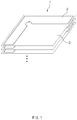
- FIG. 1 is a perspective view of an electrode unit manufactured according to an electrode unit manufacturing step in a method for manufacturing an electrode assembly according to the present invention.
- a method for manufacturing an electrode assembly may include a preparation step of preparing an electrode 2 and a separator 3 and an electrode unit manufacturing step of manufacturing an electrode unit 1 having a structure in which the electrode 2 and the separator 3 are alternately disposed.
- Each of the electrode 2 and the separator 3 may have a sheet shape.
- the electrode 2 may not have a rectangular shape or a circular shape but have an irregular shape.
- a concave part 21 (hereinafter, referred to as an 'electrode concave part') may be formed in the electrode 2.
- the electrode 2 may have an L shape.
- a recess part 23 (hereinafter, referred to as an 'electrode recess part') having a recessed shape that is curved toward the electrode 2 may be formed in the electrode concave part 21 of the electrode 2.
- the separator 3 of the manufactured electrode unit 1 may cover all of a top surface and a bottom surface of the electrode 2.
- that 'the separator covers all of the top and bottom surfaces of the electrode' may mean that the separator has an area greater than that of the electrode as well as that a circumferential portion of the separator covers circumferential portions of all the electrodes when viewed from an upper or lower side in a thickness direction of the electrode unit.
- the separator 3 may have a shape corresponding to that of the electrode.
- a concave part 31 (hereinafter, referred to a 'separator concave part') may also formed in the separator 3
- a recess part 33 (hereinafter, referred to as a 'separator recess part') having a recessed shape that is curved toward the separator 3 may also be formed in the separator concave part 31.
- the separator 3 may have an L shape.
- the method for manufacturing the electrode assembly according to the present invention may include a pre-sealing step of attaching at least partial regions of the plurality of separators within the electrode unit 1 to each other to form a pre-sealing part 40 (see FIG. 6 ).
- the separator cutting process In order to manufacture the electrode assembly having the irregular shape, in the separator cutting process, if only a partial region of the separator is cut after the electrode and the separator are only laminated alternately, the number of separators that is capable of being cut may be significantly limited.
- the present invention may provide a method for solving the above problem. That is, according to the present invention, after the electrode and the separator are alternately laminated to manufacture the electrode unit, partial regions of the separators are attached to each other, and then, a partial region of the separator is cut. Thus, when compared to the related art, a large number of separators may be cut at once. Therefore, in the process of manufacturing the electrode assembly by using the electrode unit, the number of processes of cutting the partial region of the separator may be reduced to increase in manufacturing rate of the electrode assembly.
- the pre-sealing part 40 may be formed in a partial region of the separator 3.
- the electrode concave part 21 may be formed in the electrode 2.
- the pre-sealing part may be formed at a portion or whole of the region of the separator 3, which covers the electrode concave part 21.
- the pre-sealing part 40 may be formed by pressing an upper or lower portion of the electrode unit 1.
- the pre-sealing part 40 may be formed by pressing the upper and lower portions of the electrode unit 1 at the same time.
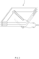
- FIG. 3 is a perspective view illustrating a state in which the pre-sealing step is performed in the method for manufacturing the electrode assembly according to the present invention
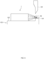
- FIG. 4 is a cross-sectional view illustrating a state in which the pre-sealing step is being performed.
- the pre-sealing step may be performed by a pre-sealing device 110 that presses the upper or lower portion of the electrode unit 1.
- FIGS. 3 and 4 illustrate an upper pressing device 112 pressing the upper portion of the electrode unit 1 and a lower pressing device 114 pressing the lower portion of the electrode unit 1 in the pre-sealing step as the pre-sealing device 110.
- the pre-sealing device 110 may include only the upper pressing device or may include only the lower pressing device.
- the upper pressing device 112 or the lower pressing device 114 may have a flat area corresponding to each of the top and bottom surfaces of the electrode unit 1. In the pre-sealing step, the upper pressing device 112 may move downward, and the lower pressing device 114 may move upward. The flat area may press the upper or lower portion of the electrode unit 1 to form the pre-sealing part.
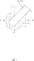
- FIG. 5 is an enlarged plan view illustrating a state in which one end of the pressing device is disposed in the pre-sealing step of the method for manufacturing the electrode assembly according to the present invention.
- the upper pressing device 112 or the lower pressing device 114 may have a bar shape.
- one end of the upper pressing device 112 and one end of the lower pressing device 114 may press a region of the separator 3 of the electrode unit 1, which is adjacent to the electrode concave part 21 of the electrode 2.
- the one end of the upper pressing device 112 and one end of the lower pressing device 114 which respectively press the regions adjacent to the electrode concave part 21, may have a curved shape. Since the curved shape is provided, the separator may be prevented from being damaged by the upper pressing device and the lower pressing device in the pre-sealing step.
- a curved surface having a curvature corresponding to that of the electrode recess part 23 may be formed in the one end of the upper pressing device 112 and the one end of the lower pressing device 114, which press the regions adjacent to the electrode concave part 21.
- a region of the pre-sealing part formed by attaching the separators to each other, which faces the electrode recess part 23, may have a shape corresponding to that of the electrode recess part 23.
- the upper pressing device 112 or the lower pressing device 114 may press the partial region of the separator to form the per-sealing part.
- the pre-sealing part may be formed biased to one side in the thickness direction of the electrode unit.
- the pre-sealing part when the partial region of the separator is pressed only downward, the pre-sealing part may be formed biased downward in the thickness direction of the electrode unit.
- the separators When the pre-sealing part is biased to one side, the separators may also be biased to one side so that the pre-sealing part has remarkably asymmetry. As a result, in the separator cutting step, cutting quality in a region in which the separator is cut may be deteriorated.
- the upper pressing device 112 may press the upper portion of the electrode unit 1 while moving downward from an upper side of the electrode unit 1 toward a center of the electrode unit 1 in the thickness direction
- the lower pressing unit 114 may press the lower portion of the electrode unit 1 while moving upward from a lower side of the electrode unit 1 toward the center of the electrode unit 1 in the thickness direction.
- the pre-sealing part 40 (see FIG. 6 ) is formed at a central portion in the thickness direction of the electrode unit and has symmetry, the cutting quality in the region in which the separator is cut may be improved in the separator cutting step.
- the method for manufacturing the electrode assembly may further include the separator cutting step of cutting a portion of the separator, which is preformed after the pre-sealing step.
- the region of the separator, which is cut in the separator cutting step may include the pre-sealing part formed in the pre-sealing step.
- the separator In the separator cutting step, the separator may have a shape corresponding to that of the electrode.
- the separator concave part 31 (see FIG. 3 ) may be formed in the separator of the electrode assembly 100, and the electrode concave part and the separator concave part may face each other.
- the separator recess part 33 (see FIG. 2 ) may be formed in the separator of the electrode assembly 100, and the electrode recess part and the separator recess part may face each other.
- the separator 3 may cover all regions of a negative electrode 2a as illustrated in FIG. 8 .
- a separation cutting line CL that is a virtual line along which the separator is cut may be formed to be spaced outward from the circumferential portion of the electrode.
- FIG. 6 is a side cross-sectional view illustrating a state in which the pre-sealing part is supported by a support device having a stepped portion in the method for manufacturing the electrode assembly according to the present invention.
- the electrode unit 1 is supported by a support device 130, and then, the pre-sealing part 40 is cut by the separator cutting device 120.
- the pre-sealing step may include a process (hereinafter, referred to as a 'stop process') of stopping movement of the upper pressing device 112 or the lower pressing device 114 to allow the pre-sealing device to continuously press the electrode unit and a process (hereinafter, referred to as a return process') of allowing the upper pressing device 112 or the lower pressing device 113 to move again so that the upper pressing device 112 or the lower pressing device 114 returns to its original position in addition to the process (hereinafter, referring to a 'moving process') of allowing the upper pressing device 112 or the lower pressing device 114 to move.
- a 'stop process' of stopping movement of the upper pressing device 112 or the lower pressing device 114 to allow the pre-sealing device to continuously press the electrode unit
- a return process' of allowing the upper pressing device 112 or the lower pressing device 113 to move again so that the upper pressing device 112 or the lower pressing device 114 returns to its original position in addition to the
- a distance at which each of the upper pressing device 112 and the lower pressing device 114 moves in the moving process may be 0.4 to 0.5 of a thickness of the electrode unit before the pre-sealing step.
- a moving distance of each of the upper pressing device 112 and the lower pressing device 114 may be 0.43 to 0.44 of the thickness of the electrode unit before the pre-sealing step.
- the sum of times taken to perform the moving process, the stop process, and the return process may be 4 seconds to 6 seconds.
- the sum of times taken to perform the moving process, the stop process, and the return process may be 4.5 seconds to 5.5 seconds.
- a ratio of a thickness of the pre-sealing part formed in the pre-sealing step to the thickness of the electrode unit may be 0.8 to 0.9.
- a ratio of a thickness of the pre-sealing part formed in the pre-sealing step to the thickness of the electrode unit may be 0.8 to 0.83.
- the pre-sealing device 110 may have a temperature of 110 degrees Celsius to 130 degrees Celsius.
- the pre-sealing device 110 may have a temperature of 115 degrees Celsius to 125 degrees Celsius.
- the pre-sealing part may be formed at the central portion in the thickness direction of the electrode unit. This may be understood that the pre-sealing part is disposed to be spaced downward from a virtual surface extending from the uppermost surface of the electrode unit and is disposed to be spaced upward from a virtual surface extending from the lowermost surface of the electrode unit(see FIG. 6 ).
- the separator cutting step may be performed in the state in which the pre-sealing part is disposed to be spaced downward from the virtual surface extending from the uppermost surface of the electrode unit and is disposed to be spaced upward from the virtual surface extending from the lowermost surface of the electrode unit. In this case, as illustrated in FIG.
- the pre-sealing part 40 when the electrode unit 1 is disposed on the support device 130, the pre-sealing part 40 may be spaced upward from a first support surface 132 supporting the bottom surface of the electrode unit in the support device 130. In this state, when the separator cutting step is performed, the pre-sealing part may not be fixed to deteriorate cutting quality in the cutting region.
- the support device 130 may include the first support surface 132 supporting the bottom surface of the electrode unit 1 and a second support surface 134 stepped with respect to the first support surface 132 and protruding upward to support the pre-sealing part 110. Since the support device is formed as described above, the pre-sealing part may be fixed in the separator cutting step to improve the cutting quality in the cutting region.
- the circumferential part of the separator covers the circumferential portion of the electrode so that the separator covers all the regions of the separator in the electrode unit.
- the separator of the electrode unit does not cover the all the regions of the electrode, the positive electrode and the negative electrode, which face each other with the separator therebetween, may contact each other. In this case, short circuit may occur to cause a serious safety problem.
- the separator cover all the regions of the electrode in the electrode unit after the separator cutting step according to the present invention.
- the present invention may be applied to an electrode assembly used for a lithium secondary battery.
- the negative electrode and the positive electrode which face each other with the separator therebetween, if the negative electrode does not cover all regions of the positive electrode, lithium ions may be extracted.
- the positive electrode and the negative electrode may be provided so that the circumferential portion of the negative electrode surrounds the circumferential portion of the positive electrode to allow the negative electrode to cover all the regions of the positive electrode.
- the circumferential portion of the separator may be formed to surround the circumferential portion of the negative electrode in the electrode unit.
- the distance D1 may be 0.5 mm or more in all regions of the electrode assembly.
- the distance D1 is 0.5 mm or more, the safety problem due to direct contact between the electrodes may be solved.
- the separator cutting step if a horizontal distance between the separation cutting line CL that is the virtual line along which the separator is cut and the circumferential portion of the negative electrode is D2, it is preferable that the distance D2 is greater than the distance D1. There may be a certain difference between the separator cutting line CL and the circumferential portion of the actual separator after the separator cutting step due to surrounding environments, vibration of the separator cutting device in the separator cutting step, and the like. If the difference between the distance D2 and the distance D1 is excessively less, a region having a distance less than 0.5 mm may occur in a partial region of the electrode assembly to cause the safety problem of the electrode assembly.
- the distance D2 may be greater than the distance D1.
- a distance between the distances D2 and D1 may be 0.5 mm to 0.7 mm in all regions in which the cutting of the separator is performed.
- a distance between the distances D2 and D1 may be 0.6 mm to 0.7 mm in all the regions of the electrode assembly.
- the method for manufacturing the electrode assembly may further include a side sealing step of bonding the plurality of separators cut in the separator cutting step to each other.
- the plurality of separators cut in the separator cutting step may be bonded to each other to minimize a degree of protrusion of the separator to the outside, thereby minimizing a volume of the electrode assembly.
- the region in which the plurality of separators are bonded to each other may be limited to only the region in which the plurality of separators are cut.
- the region in which the plurality of separators are bonded to each other may include a region in which the plurality of separators are not cut in the separator cutting step.
- the pre-sealing device may have a shape different from that of FIGS. 3 to 5 . That is, each of the upper sealing device and the lower sealing device, which constitute the pre-sealing device, may have a shape corresponding to the region in which the separator is cut in the separator cutting step so as to cover the entire region in which the separator is cut in the separator cutting step. In this case, in the pre-sealing step, the pre-sealing part may be formed over the entire region in which the separator will be cut. However, in this case, each of one end of the upper pressing device and one end of the lower pressing device may have a shape corresponding to the electrode recess part to press the region adjacent to the electrode recess part 23 (see FIG. 2 ) of the electrode 2.
- An apparatus for manufacturing an electrode assembly may include an electrode unit manufacturing device manufacturing an electrode unit 1 having a structure in which a separator 3 and an electrode 2 are alternately disposed, a pre-sealing device 10 which attaches at least partial regions of the plurality of separators within the electrode unit 1 to each other to form a pre-sealing part 40 and a separator cutting device which cuts a region of the plurality of separators 3, which includes the pre-sealing part 40.
- a concave part may be formed in the electrode 2, and the pre-sealing device 110 may form the pre-sealing part 40 on at least a portion of a region of the plurality of separators 3, which covers an electrode concave part 21 of the electrode 2. Also, the separator cutting device 120 may form a separator concave part 31 at a position of the separator 3, which corresponds to the electrode concave part 21 of the electrode 2.
- the apparatus for the electrode assembly according to the present invention may further include a side sealing device which bonds the regions cut by the separator cutting device 120 to each other and a support device 130 supporting the electrode unit 1 and the pre-sealing part 40.
- the support device 130 may include a first support surface 132 supporting the bottom surface of the electrode unit 1 and a second support surface stepped with respect to the first support surface 132 and protruding upward to support the pre-sealing part 40.
- the pre-sealing device 110 may include an upper pressing device 112 pressing the upper portion of the electrode unit 1 and a lower pressing device 114 pressing the lower portion of the electrode unit 1. Also, each of the upper pressing device 112 and the lower pressing device 114 may have a bar shape. One end of each of the upper pressing device 112 and the lower pressing device 114 may press a region of the separator 3, which is adjacent to the electrode concave part 21 of the electrode 2.
- An electrode recess part 23 having a curved shape that is recessed toward the electrode 2 may be formed in the electrode concave 21 of the electrode 2.
- One end of each of the upper pressing device 112 and the lower pressing device 114 which press the region of the separator 3, which is adjacent to the electrode concave part 21 of the electrode 2 may have a curved surface having a curvature corresponding to that of the electrode recess part 23.
- An electrode unit having a structure in which an electrode and a separator are alternately laminated and including 28 sheets of separators was prepared.
- the electrode unit was manufactured by laminating 14 mono cells, each of which includes two separators as a four-layered structure of a positive electrode, the separator, a negative electrode, and the separator.
- the electrode unit had a total thickness of 3.42 mm, and each of the positive electrode and the negative electrode had an L shape. Also, a recess part was formed in each of concave parts of the positive electrode and the negative electrodes. Here, the recess part formed in the concave part of the negative electrode had a curvature radius of 4.5 mm.
- each of the upper pressing device and the lower pressing device, which press the electrode unit had a bar shape having a width of 5 mm.
- a pre-sealing part was formed in a region of the separator, which is pressed by the upper pressing device and the lower pressing device.
- each of the one end of the upper pressing device and the one end of the lower pressing device, which press the region adjacent to the electrode recess part had a curvature radius of 2.5 mm.
- the upper pressing device and the lower pressing device moved downward and upward by a distance 1.5 mm for 1 second at a temperature of 120 degrees Celsius. Thereafter, the upper pressing device and the lower pressing device were stopped for 3 seconds. Thereafter, the upper pressing device and the lower pressing device moved upward and downward by a distance 1.5 mm for 1 second, respectively.
- the pre-sealing part formed in the pre-sealing step had a thickness of 0.28 mm.
- a partial region of the separator was cut so that the separator has a shape corresponding to that of the electrode.
- the partial region of the separator was cut so that a horizontal distance (i.e., a distance between a circumferential portion of the negative electrode and a cutting line of the separator when the electrode unit is viewed from an upper side) between a circumferential portion of the negative electrode and a cutting line of the separator is 1.1 mm.
- a region of the separator cutting line, which corresponds to the recess part of the negative electrode had a curvature radius of 3.4 mm.
- the horizontal distance between the circumferential portion of the separator and the circumferential portion of the negative electrode in the region in which the separator is cut was measured in a first circumferential region 1 of a concave part of the electrode and the separator, a recess part region 2, and a second circumferential region 3 of the concave part of the electrode and of the separator.
- the horizontal distance between the circumferential portion of the separator and the circumferential portion of the negative electrode was measured with respect to 28 separators, which constitute the electrode assembly manufactured according to Embodiment.
- FIG. 9 the horizontal distance between the circumferential portion of the separator and the circumferential portion of the negative electrode in the region in which the separator is cut was measured in a first circumferential region 1 of a concave part of the electrode and the separator, a recess part region 2, and a second circumferential region 3 of the concave part of the electrode and of the separator.
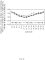
- FIG. 10 is a graph view illustrating results obtained by measuring the horizontal distance between the circumferential portion of the separator and the circumferential portion of the negative electrode in the regions 1 to 3 with respect to each of the 28 separators constituting the electrode unit manufactured according to Embodiment.
- Numbers expressed on a horizontal axis indicate positions of the separators sequentially measured from the uppermost end in a thickness direction of the electrode unit.
- the separators are listed in pairs by 1, 2/3, 4/5, 6 .. (abbreviated below) on the horizontal axis of FIG. 10 . This means that the horizontal distance between the entire circumferential portion of two separators and the circumferential portion of the negative electrode, which constitute one mono cell, was measured.
- a horizontal distance between the entire circumferential portion of the two sheets of separators within one mono cell and the circumferential portion of the negative electrode within the mono cell to which the two sheets of separators belong was measured for each mono cell (i.e., measured 14 times in each of the regions 1 to 3) to measure the distance between the circumferential portion of the separator and the circumferential portion of the negative electrode, and the results are shown in FIG. 10 .
- the distance between the circumferential portion of the separator and the circumferential portion of the negative electrode needs to be 0.5 mm or more in all the regions of the electrode assembly. Therefore, as illustrated in FIG. 10 , in the case of the electrode assembly manufactured according to Embodiment, it was confirmed that the distance between the circumferential portion of the separator and the circumferential portion of the negative electrode is 0.5 mm or more in the entire region, which is cut in the separator cutting step.
- Position Region 1 Region 2 Region 3 Measurement Value Mean Distance 1.17 1.25 1.20 Maximum Distance 1.76 1.69 1.64 Minimum Distance 0.73 0.94 0.73 Standard Deviation 0.24 0.17 0.20 Process Capability Index (Cpk) 1. 90 2.93 2.17
- Table 1 shows a mean value, a maximum value, a minimum value, a standard deviation, and a process capability index (CpK) with respect to the horizontal distance between the circumferential portion of the separator and the circumferential portion of the negative electrode in the regions 1 to 3 with respect to all the separators of the eight electrode assemblies manufactured according to Embodiment.
- CpK process capability index
Landscapes
- Chemical & Material Sciences (AREA)
- Chemical Kinetics & Catalysis (AREA)
- Electrochemistry (AREA)
- General Chemical & Material Sciences (AREA)
- Engineering & Computer Science (AREA)
- Manufacturing & Machinery (AREA)
- Secondary Cells (AREA)
Abstract
Description
- The present application claims the benefit of the priority of Korean Patent Application No.
10-2018-0019991, filed on February 20, 2018 - The present invention relates to an apparatus and method for manufacturing an electrode assembly, and more particularly, to an apparatus and method for manufacturing an electrode assembly, which have improved productivity when compared to an apparatus and method for manufacturing an electrode assembly according to the related art.
- As the demands for electronic devices increase, the demands for secondary batteries, which are accommodated in electronic devices and repeatedly chargeable and dischargeable, also increase.
- Particularly, as the electronic device is diversified in shape, and the capacity required for the electronic device increases, it is required to deviate from the conventional shape of the secondary battery so as to be mounted in an irregular space within the electronic device and to maximize the capacity. Various studies for effectively manufacturing the secondary batteries having irregular shapes are being conducted.
- In order to manufacture such an irregular secondary battery, it is necessary to manufacture an electrode assembly having an irregular shape corresponding to the irregular secondary battery.
- According to the related art, in order to manufacture the electrode assembly having the irregular shape, a separator (generally, the separator has a rectangular shape) and an electrode having an irregular shape are provided and then are laminated to manufacture an electrode unit. Thereafter, a partial region of the separator may also be cut to have a shape corresponding to that of the electrode, thereby manufacturing an electrode assembly having an irregular shape.
- However, according to the related art, while the partial region of the separator is cut, the number of separators to be cut may be limited. That is, in the case in which the electrode unit is constituted by a large number of separators, while the partial region of the separator is cut, the separator may not be properly cut, or the cut point is deteriorated in quality.
- Thus, according to the related art, the electrode unit in which the partial region of the separator is cut may be constituted by only a relatively small number of electrodes and separators. However, the electrode assembly used for the secondary battery is constituted by a relatively large number of electrodes and separators. As a result, according to the related art, since a large number of electrode units in which the partial region of the separator is cut is required to manufacture the electrode assembly, there is a problem that excessive equipment and manufacturing time are required for manufacturing the electrode assembly having the irregular shape.
- Thus, an object of the present invention is to reduce equipment and manufacturing time, which are required for manufacturing an electrode assembly by simplifying a process of manufacturing the electrode assembly.
- To achieve the above object, a method for manufacturing an electrode assembly according to an aspect of the present invention includes: a preparation step of preparing a separator and an electrode; an electrode unit manufacturing step of manufacturing an electrode unit having a structure in which the separator and the electrode are alternately disposed; a pre-sealing step of forming a pre-sealing part in which at least partial regions of the plurality of separators within the electrode unit are attached to each other; and a separator cutting step of cutting a region of the plurality of separators, which includes the pre-sealing part.
- In the preparation step, a concave part may be formed in the electrode, in the pre-sealing step, the pre-sealing part may be formed on at least a portion of the plurality of separators, which covers the concave part of the electrode, and in the separator cutting step, a concave part may be formed in the separator, which corresponds to the concave part of the electrode.
- In the pre-sealing step, upper and lower potions of the electrode unit may be pressed at the same time to form the pre-sealing part.
- The method may further include a side sealing step of bonding the plurality of separators cut in the separator cutting step to each other.
- the separator cutting step may be performed in a state in which the pre-sealing part is disposed to be spaced downward from a virtual surface extending from the uppermost surface of the electrode unit and be disposed to be spaced upward from a virtual surface extending from the lowermost surface of the electrode unit.
- Each of an upper pressing device and a lower pressing device may have a bar shape, and in the pre-sealing step, one end of each of the upper pressing device and the lower pressing device may press a region of the separator, which is adjacent to the concave part of the electrode.
- A recess part having a recessed shape that is curved toward the electrode may be formed in the concave part of the electrode, and in the pre-sealing step, a curved surface having a curvature corresponding to that of the recess part may be formed in one end of each of the upper pressing device and the lower pressing device, which press a region of the separator, which is adjacent to the concave part of the electrode.
- In the pre-sealing step, the upper pressing device may press an upper portion of the electrode unit while moving downward from an upper side of the electrode unit toward a center of the electrode unit in a thickness direction, and the lower pressing unit may press a lower portion of the electrode unit while moving upward from a lower side of the electrode unit toward the center of the electrode unit in the thickness direction.
- To achieve the above object, an apparatus for manufacturing an electrode assembly according to another aspect of the present invention includes: an electrode unit manufacturing device manufacturing an electrode unit having a separator and an electrode are alternately disposed; a pre-sealing device which attaches at least partial regions of the plurality of separators within the electrode unit to each other to from a pre-sealing part; and a separator cutting device cutting a region of the plurality of separators, which includes the pre-sealing part.
- A concave part may be formed in the electrode, the pre-sealing device may form the pre-sealing part on at least a portion of the plurality of separators, which covers the concave part of the electrode, and the separator cutting device may form the concave part in the separator, which corresponds to the concave part of the electrode.
- The apparatus may further include a side sealing device which bonds the plurality of separators cut by the separator cutting device to each other.
- The apparatus may further include a support device supporting the electrode unit and the pre-sealing part, wherein the support device may include: a first support surface supporting a bottom surface of the electrode unit; and a second support surface stepped with respect to the first support surface and protruding upward to support the pre-sealing part.
- The pre-sealing device may include: an upper pressing device pressing an upper portion of the electrode unit; and a lower pressing device pressing a lower portion of the electrode unit, wherein each of the upper pressing device and the lower pressing device may have a bar shape, and one end of each of the upper pressing device and the lower pressing device may press a region of the separator, which is adjacent to the electrode concave part of the electrode.
- A recess part having a recessed shape that is curved toward the electrode may be formed in the concave part of the electrode, and a curved surface having a curvature corresponding to that of the recess part may be formed in one end of each of the upper pressing device and the lower pressing device which press the region of the separator, which is adjacent to the concave part of the electrode.
- The upper pressing device may press the upper portion of the electrode unit while moving downward from an upper side of the electrode unit toward a center of the electrode unit in a thickness direction, and the lower pressing unit may press the lower portion of the electrode unit while moving upward from a lower side of the electrode unit toward the center of the electrode unit in the thickness direction.
- According to the present invention, the process of manufacturing the electrode assembly may be simplified to reduce the equipment and manufacturing time.
-
-
FIG. 1 is a perspective view of an electrode unit manufactured according to an electrode unit manufacturing step in a method for manufacturing an electrode assembly according to the present invention. -
FIG. 2 is a plan view illustrating an example of shapes of an electrode and a separator, which are used in the method for manufacturing the electrode assembly according to the present invention. -
FIG. 3 is a perspective view illustrating a state in which a pre-sealing step is being performed in the method for manufacturing the electrode assembly according to the present invention. -
FIG. 4 is a side cross-sectional view illustrating a state in which the pre-sealing step is being performed in the method for manufacturing the electrode assembly according to the present invention. -
FIG. 5 is an enlarged plan view illustrating a state in which one end of a pressing device is disposed in the pre-sealing step of the method for manufacturing the electrode assembly according to the present invention. -
FIG. 6 is a side cross-sectional view illustrating a state in which a pre-sealing part is supported by a support device having a stepped portion in a separator cutting step of the method for manufacturing the electrode assembly according to the present invention. -
FIG. 7 is a perspective view illustrating an example of an electrode assembly manufactured according to the method for manufacturing the electrode assembly according to present invention. -
FIG. 8 is an enlarged plan view of a point at which the separator is cut after the separation cutting step of the method for manufacturing the electrode assembly according to present invention. -
FIG. 9 is a plan view illustrating a point at which a horizontal distance between a circumferential portion of the separator and a circumferential portion of a negative electrode is measured through an experimental example with respect to the electrode assembly manufactured according to an embodiment of the prevent invention. -
FIG. 10 is a graph view illustrating results obtained by measuring the horizontal distance between the circumferential portion of the separator and the circumferential portion of the negative electrode through the experimental example with respect to the electrode assembly manufactured according to an embodiment of the prevent invention. - Hereinafter, a method for manufacturing an electrode assembly according to the present invention will be described with reference to the accompanying drawings.
-
FIG. 1 is a perspective view of an electrode unit manufactured according to an electrode unit manufacturing step in a method for manufacturing an electrode assembly according to the present invention. - Referring to
FIG. 1 , a method for manufacturing an electrode assembly according to an embodiment of the present invention may include a preparation step of preparing anelectrode 2 and aseparator 3 and an electrode unit manufacturing step of manufacturing anelectrode unit 1 having a structure in which theelectrode 2 and theseparator 3 are alternately disposed. Each of theelectrode 2 and theseparator 3 may have a sheet shape. - In the preparation step, the
electrode 2 may not have a rectangular shape or a circular shape but have an irregular shape. For example, as illustrated inFIG. 2 , a concave part 21 (hereinafter, referred to as an 'electrode concave part') may be formed in theelectrode 2. For example, theelectrode 2 may have an L shape. - Subsequently, referring to
FIG. 2 , a recess part 23 (hereinafter, referred to as an 'electrode recess part') having a recessed shape that is curved toward theelectrode 2 may be formed in the electrode concave part 21 of theelectrode 2. - In the electrode unit manufacturing step, the
separator 3 of the manufacturedelectrode unit 1 may cover all of a top surface and a bottom surface of theelectrode 2. Here, that 'the separator covers all of the top and bottom surfaces of the electrode' may mean that the separator has an area greater than that of the electrode as well as that a circumferential portion of the separator covers circumferential portions of all the electrodes when viewed from an upper or lower side in a thickness direction of the electrode unit. - As described below, after the separator cutting step, the
separator 3 may have a shape corresponding to that of the electrode. Thus, referring toFIG. 2 , similar to the case of theelectrode 2, after the separator cutting step, a concave part 31 (hereinafter, referred to a 'separator concave part') may also formed in theseparator 3, and a recess part 33 (hereinafter, referred to as a 'separator recess part') having a recessed shape that is curved toward theseparator 3 may also be formed in the separator concave part 31. In addition, after the separator cutting step, theseparator 3 may have an L shape. - The method for manufacturing the electrode assembly according to the present invention may include a pre-sealing step of attaching at least partial regions of the plurality of separators within the
electrode unit 1 to each other to form a pre-sealing part 40 (seeFIG. 6 ). - In order to manufacture the electrode assembly having the irregular shape, in the separator cutting process, if only a partial region of the separator is cut after the electrode and the separator are only laminated alternately, the number of separators that is capable of being cut may be significantly limited.
- The present invention may provide a method for solving the above problem. That is, according to the present invention, after the electrode and the separator are alternately laminated to manufacture the electrode unit, partial regions of the separators are attached to each other, and then, a partial region of the separator is cut. Thus, when compared to the related art, a large number of separators may be cut at once. Therefore, in the process of manufacturing the electrode assembly by using the electrode unit, the number of processes of cutting the partial region of the separator may be reduced to increase in manufacturing rate of the electrode assembly.
- In the pre-sealing step, the
pre-sealing part 40 may be formed in a partial region of theseparator 3. As described above, the electrode concave part 21 may be formed in theelectrode 2. According to the present invention, the pre-sealing part may be formed at a portion or whole of the region of theseparator 3, which covers the electrode concave part 21. - In the pre-sealing step, the
pre-sealing part 40 may be formed by pressing an upper or lower portion of theelectrode unit 1. For example, thepre-sealing part 40 may be formed by pressing the upper and lower portions of theelectrode unit 1 at the same time. -
FIG. 3 is a perspective view illustrating a state in which the pre-sealing step is performed in the method for manufacturing the electrode assembly according to the present invention, andFIG. 4 is a cross-sectional view illustrating a state in which the pre-sealing step is being performed. - As illustrated in
FIGS. 3 and4 , the pre-sealing step may be performed by apre-sealing device 110 that presses the upper or lower portion of theelectrode unit 1.FIGS. 3 and4 illustrate an upperpressing device 112 pressing the upper portion of theelectrode unit 1 and a lowerpressing device 114 pressing the lower portion of theelectrode unit 1 in the pre-sealing step as thepre-sealing device 110. However, unlikeFIGS. 3 and4 , thepre-sealing device 110 may include only the upper pressing device or may include only the lower pressing device. - The upper
pressing device 112 or the lowerpressing device 114 may have a flat area corresponding to each of the top and bottom surfaces of theelectrode unit 1. In the pre-sealing step, the upperpressing device 112 may move downward, and the lowerpressing device 114 may move upward. The flat area may press the upper or lower portion of theelectrode unit 1 to form the pre-sealing part. -
FIG. 5 is an enlarged plan view illustrating a state in which one end of the pressing device is disposed in the pre-sealing step of the method for manufacturing the electrode assembly according to the present invention. - Also, as illustrated in
FIGS. 3 to 5 , the upperpressing device 112 or the lowerpressing device 114 may have a bar shape. Here, in the pre-sealing step, one end of the upperpressing device 112 and one end of the lowerpressing device 114 may press a region of theseparator 3 of theelectrode unit 1, which is adjacent to the electrode concave part 21 of theelectrode 2. - Also, as illustrated in
FIG. 5 , the one end of the upperpressing device 112 and one end of the lowerpressing device 114, which respectively press the regions adjacent to the electrode concave part 21, may have a curved shape. Since the curved shape is provided, the separator may be prevented from being damaged by the upper pressing device and the lower pressing device in the pre-sealing step. For example, a curved surface having a curvature corresponding to that of theelectrode recess part 23 may be formed in the one end of the upperpressing device 112 and the one end of the lowerpressing device 114, which press the regions adjacent to the electrode concave part 21. Thus, in the pre-sealing step, a region of the pre-sealing part formed by attaching the separators to each other, which faces theelectrode recess part 23, may have a shape corresponding to that of theelectrode recess part 23. - As described above, in the pre-sealing step, the upper
pressing device 112 or the lowerpressing device 114 may press the partial region of the separator to form the per-sealing part. When the partial region of the separator is pressed only upward or downward in the pre-sealing step, the pre-sealing part may be formed biased to one side in the thickness direction of the electrode unit. For example, in the pre-sealing step, when the partial region of the separator is pressed only downward, the pre-sealing part may be formed biased downward in the thickness direction of the electrode unit. When the pre-sealing part is biased to one side, the separators may also be biased to one side so that the pre-sealing part has remarkably asymmetry. As a result, in the separator cutting step, cutting quality in a region in which the separator is cut may be deteriorated. - Thus, as illustrated in
FIG. 4 , according to the present invention, in the pre-sealing step, the upperpressing device 112 may press the upper portion of theelectrode unit 1 while moving downward from an upper side of theelectrode unit 1 toward a center of theelectrode unit 1 in the thickness direction, and the lowerpressing unit 114 may press the lower portion of theelectrode unit 1 while moving upward from a lower side of theelectrode unit 1 toward the center of theelectrode unit 1 in the thickness direction. In this case, since the pre-sealing part 40 (seeFIG. 6 ) is formed at a central portion in the thickness direction of the electrode unit and has symmetry, the cutting quality in the region in which the separator is cut may be improved in the separator cutting step. - According to the present invention, the method for manufacturing the electrode assembly may further include the separator cutting step of cutting a portion of the separator, which is preformed after the pre-sealing step. The region of the separator, which is cut in the separator cutting step, may include the pre-sealing part formed in the pre-sealing step.
- In the separator cutting step, the separator may have a shape corresponding to that of the electrode. Thus, as illustrated in
FIG. 7 , after the separator cutting step, the separator concave part 31 (seeFIG. 3 ) may be formed in the separator of theelectrode assembly 100, and the electrode concave part and the separator concave part may face each other. Also, after the separator cutting step, the separator recess part 33 (seeFIG. 2 ) may be formed in the separator of theelectrode assembly 100, and the electrode recess part and the separator recess part may face each other. - Here, in order to prevent a positive electrode and a negative electrode, which constitute the electrode, from directly contacting each other, in the separator cutting step, the
separator 3 may cover all regions of anegative electrode 2a as illustrated inFIG. 8 . Thus, as illustrated inFIG. 5 , in the separator cutting step, a separation cutting line CL that is a virtual line along which the separator is cut may be formed to be spaced outward from the circumferential portion of the electrode. -
FIG. 6 is a side cross-sectional view illustrating a state in which the pre-sealing part is supported by a support device having a stepped portion in the method for manufacturing the electrode assembly according to the present invention. - As illustrated in
FIG. 6 , in the separator cutting step, theelectrode unit 1 is supported by asupport device 130, and then, thepre-sealing part 40 is cut by theseparator cutting device 120. - The pre-sealing step may include a process (hereinafter, referred to as a 'stop process') of stopping movement of the upper
pressing device 112 or the lowerpressing device 114 to allow the pre-sealing device to continuously press the electrode unit and a process (hereinafter, referred to as a return process') of allowing the upperpressing device 112 or the lower pressing device 113 to move again so that the upperpressing device 112 or the lowerpressing device 114 returns to its original position in addition to the process (hereinafter, referring to a 'moving process') of allowing the upperpressing device 112 or the lowerpressing device 114 to move. - Here, when the
pre-sealing device 110 includes all of the upperpressing device 112 and the lowerpressing device 114, a distance at which each of the upperpressing device 112 and the lowerpressing device 114 moves in the moving process may be 0.4 to 0.5 of a thickness of the electrode unit before the pre-sealing step. For example, in the moving process, a moving distance of each of the upperpressing device 112 and the lowerpressing device 114 may be 0.43 to 0.44 of the thickness of the electrode unit before the pre-sealing step. - In the pre-sealing process, the sum of times taken to perform the moving process, the stop process, and the return process may be 4 seconds to 6 seconds. For example, the sum of times taken to perform the moving process, the stop process, and the return process may be 4.5 seconds to 5.5 seconds.
- Also, in the pre-sealing step, a ratio of a thickness of the pre-sealing part formed in the pre-sealing step to the thickness of the electrode unit may be 0.8 to 0.9. For example, in the pre-sealing step, a ratio of a thickness of the pre-sealing part formed in the pre-sealing step to the thickness of the electrode unit may be 0.8 to 0.83.
- In the pre-sealing step, the
pre-sealing device 110 may have a temperature of 110 degrees Celsius to 130 degrees Celsius. For example, in the pre-sealing step, thepre-sealing device 110 may have a temperature of 115 degrees Celsius to 125 degrees Celsius. - As described above, in the pre-sealing step, the pre-sealing part may be formed at the central portion in the thickness direction of the electrode unit. This may be understood that the pre-sealing part is disposed to be spaced downward from a virtual surface extending from the uppermost surface of the electrode unit and is disposed to be spaced upward from a virtual surface extending from the lowermost surface of the electrode unit(see
FIG. 6 ). Thus, the separator cutting step may be performed in the state in which the pre-sealing part is disposed to be spaced downward from the virtual surface extending from the uppermost surface of the electrode unit and is disposed to be spaced upward from the virtual surface extending from the lowermost surface of the electrode unit. In this case, as illustrated inFIG. 6 , when theelectrode unit 1 is disposed on thesupport device 130, thepre-sealing part 40 may be spaced upward from afirst support surface 132 supporting the bottom surface of the electrode unit in thesupport device 130. In this state, when the separator cutting step is performed, the pre-sealing part may not be fixed to deteriorate cutting quality in the cutting region. - Thus, according to the present invention, in the separator cutting step, the
support device 130 may include thefirst support surface 132 supporting the bottom surface of theelectrode unit 1 and asecond support surface 134 stepped with respect to thefirst support surface 132 and protruding upward to support thepre-sealing part 110. Since the support device is formed as described above, the pre-sealing part may be fixed in the separator cutting step to improve the cutting quality in the cutting region. - It is preferable that the circumferential part of the separator covers the circumferential portion of the electrode so that the separator covers all the regions of the separator in the electrode unit. When the separator of the electrode unit does not cover the all the regions of the electrode, the positive electrode and the negative electrode, which face each other with the separator therebetween, may contact each other. In this case, short circuit may occur to cause a serious safety problem. Thus, it is preferable that the separator cover all the regions of the electrode in the electrode unit after the separator cutting step according to the present invention.
- Also, the present invention may be applied to an electrode assembly used for a lithium secondary battery. In this case, in the relationship between the negative electrode and the positive electrode, which face each other with the separator therebetween, if the negative electrode does not cover all regions of the positive electrode, lithium ions may be extracted. Thus, the positive electrode and the negative electrode may be provided so that the circumferential portion of the negative electrode surrounds the circumferential portion of the positive electrode to allow the negative electrode to cover all the regions of the positive electrode.
- Thus, in summary of the above contents, after the separator cutting step, the circumferential portion of the separator may be formed to surround the circumferential portion of the negative electrode in the electrode unit.
- Here, as illustrated in
FIG. 8 , after the separator cutting step, if a horizontal distance (i.e., a distance between the circumferential portion of the separator and the circumferential portion of the negative electrode when the electrode unit is viewed from an upper side) between the circumferential portion of the separator and the circumferential portion of the negative electrode is D1, the distance D1 according to the present invention may be 0.5 mm or more in all regions of the electrode assembly. When the distance D1 is 0.5 mm or more, the safety problem due to direct contact between the electrodes may be solved. - In the separator cutting step, if a horizontal distance between the separation cutting line CL that is the virtual line along which the separator is cut and the circumferential portion of the negative electrode is D2, it is preferable that the distance D2 is greater than the distance D1. There may be a certain difference between the separator cutting line CL and the circumferential portion of the actual separator after the separator cutting step due to surrounding environments, vibration of the separator cutting device in the separator cutting step, and the like. If the difference between the distance D2 and the distance D1 is excessively less, a region having a distance less than 0.5 mm may occur in a partial region of the electrode assembly to cause the safety problem of the electrode assembly.
- Thus, according to the present invention, the distance D2 may be greater than the distance D1. Here, a distance between the distances D2 and D1 may be 0.5 mm to 0.7 mm in all regions in which the cutting of the separator is performed. For example, a distance between the distances D2 and D1 may be 0.6 mm to 0.7 mm in all the regions of the electrode assembly.
- Also, according to the present invention, the method for manufacturing the electrode assembly may further include a side sealing step of bonding the plurality of separators cut in the separator cutting step to each other. The plurality of separators cut in the separator cutting step may be bonded to each other to minimize a degree of protrusion of the separator to the outside, thereby minimizing a volume of the electrode assembly. In the side sealing step, the region in which the plurality of separators are bonded to each other may be limited to only the region in which the plurality of separators are cut. On the other hand, in the side sealing step, the region in which the plurality of separators are bonded to each other may include a region in which the plurality of separators are not cut in the separator cutting step.
- The pre-sealing device may have a shape different from that of
FIGS. 3 to 5 . That is, each of the upper sealing device and the lower sealing device, which constitute the pre-sealing device, may have a shape corresponding to the region in which the separator is cut in the separator cutting step so as to cover the entire region in which the separator is cut in the separator cutting step. In this case, in the pre-sealing step, the pre-sealing part may be formed over the entire region in which the separator will be cut. However, in this case, each of one end of the upper pressing device and one end of the lower pressing device may have a shape corresponding to the electrode recess part to press the region adjacent to the electrode recess part 23 (seeFIG. 2 ) of theelectrode 2. - The technical effects of the numerical ranges in connection with the present invention may be supported by the following embodiments.
- Hereinafter, an apparatus for manufacturing an electrode assembly according to the present invention will be described with reference to the above-described contents and the accompanying drawings.
- An apparatus for manufacturing an electrode assembly according to the present invention may include an electrode unit manufacturing device manufacturing an
electrode unit 1 having a structure in which aseparator 3 and anelectrode 2 are alternately disposed, a pre-sealing device 10 which attaches at least partial regions of the plurality of separators within theelectrode unit 1 to each other to form apre-sealing part 40 and a separator cutting device which cuts a region of the plurality ofseparators 3, which includes thepre-sealing part 40. - Here, a concave part may be formed in the
electrode 2, and thepre-sealing device 110 may form thepre-sealing part 40 on at least a portion of a region of the plurality ofseparators 3, which covers an electrode concave part 21 of theelectrode 2. Also, theseparator cutting device 120 may form a separator concave part 31 at a position of theseparator 3, which corresponds to the electrode concave part 21 of theelectrode 2. - The apparatus for the electrode assembly according to the present invention may further include a side sealing device which bonds the regions cut by the
separator cutting device 120 to each other and asupport device 130 supporting theelectrode unit 1 and thepre-sealing part 40. Thesupport device 130 may include afirst support surface 132 supporting the bottom surface of theelectrode unit 1 and a second support surface stepped with respect to thefirst support surface 132 and protruding upward to support thepre-sealing part 40. - The
pre-sealing device 110 may include an upperpressing device 112 pressing the upper portion of theelectrode unit 1 and a lowerpressing device 114 pressing the lower portion of theelectrode unit 1. Also, each of the upperpressing device 112 and the lowerpressing device 114 may have a bar shape. One end of each of the upperpressing device 112 and the lowerpressing device 114 may press a region of theseparator 3, which is adjacent to the electrode concave part 21 of theelectrode 2. - An
electrode recess part 23 having a curved shape that is recessed toward theelectrode 2 may be formed in the electrode concave 21 of theelectrode 2. One end of each of the upperpressing device 112 and the lowerpressing device 114 which press the region of theseparator 3, which is adjacent to the electrode concave part 21 of theelectrode 2 may have a curved surface having a curvature corresponding to that of theelectrode recess part 23. - An electrode unit having a structure in which an electrode and a separator are alternately laminated and including 28 sheets of separators was prepared. The electrode unit was manufactured by laminating 14 mono cells, each of which includes two separators as a four-layered structure of a positive electrode, the separator, a negative electrode, and the separator.
- The electrode unit had a total thickness of 3.42 mm, and each of the positive electrode and the negative electrode had an L shape. Also, a recess part was formed in each of concave parts of the positive electrode and the negative electrodes. Here, the recess part formed in the concave part of the negative electrode had a curvature radius of 4.5 mm.
- In a pre-sealing step, each of the upper pressing device and the lower pressing device, which press the electrode unit, had a bar shape having a width of 5 mm. In the pre-sealing step, a pre-sealing part was formed in a region of the separator, which is pressed by the upper pressing device and the lower pressing device. Also, in the pre-sealing step, each of the one end of the upper pressing device and the one end of the lower pressing device, which press the region adjacent to the electrode recess part, had a curvature radius of 2.5 mm.
- In the pre-sealing step, the upper pressing device and the lower pressing device moved downward and upward by a distance 1.5 mm for 1 second at a temperature of 120 degrees Celsius. Thereafter, the upper pressing device and the lower pressing device were stopped for 3 seconds. Thereafter, the upper pressing device and the lower pressing device moved upward and downward by a distance 1.5 mm for 1 second, respectively.
- The pre-sealing part formed in the pre-sealing step had a thickness of 0.28 mm.
- In a separator cutting step after the pre-sealing step, a partial region of the separator was cut so that the separator has a shape corresponding to that of the electrode. In the separator cutting step, the partial region of the separator was cut so that a horizontal distance (i.e., a distance between a circumferential portion of the negative electrode and a cutting line of the separator when the electrode unit is viewed from an upper side) between a circumferential portion of the negative electrode and a cutting line of the separator is 1.1 mm. Here, a region of the separator cutting line, which corresponds to the recess part of the negative electrode had a curvature radius of 3.4 mm.
- Total eight electrode assemblies were measured according to Embodiment.
- In the eight electrode assemblies manufactured according to Embodiment, a horizontal distance between a circumferential portion of a separator and a circumferential portion of a negative electrode in a region of the separator, which is cut in a separator cutting step, was measured.
- As illustrated in
FIG. 9 , the horizontal distance between the circumferential portion of the separator and the circumferential portion of the negative electrode in the region in which the separator is cut was measured in a firstcircumferential region ① of a concave part of the electrode and the separator, arecess part region ②, and a secondcircumferential region ③ of the concave part of the electrode and of the separator. The horizontal distance between the circumferential portion of the separator and the circumferential portion of the negative electrode was measured with respect to 28 separators, which constitute the electrode assembly manufactured according to Embodiment.FIG. 10 is a graph view illustrating results obtained by measuring the horizontal distance between the circumferential portion of the separator and the circumferential portion of the negative electrode in theregions ① to ③ with respect to each of the 28 separators constituting the electrode unit manufactured according to Embodiment. Numbers expressed on a horizontal axis indicate positions of the separators sequentially measured from the uppermost end in a thickness direction of the electrode unit. Here, the separators are listed in pairs by 1, 2/3, 4/5, 6 .. (abbreviated below) on the horizontal axis ofFIG. 10 . This means that the horizontal distance between the entire circumferential portion of two separators and the circumferential portion of the negative electrode, which constitute one mono cell, was measured. That is, in theregions ① to ③ of the electrode unit including 28 sheets of separators according to Embodiment, a horizontal distance between the entire circumferential portion of the two sheets of separators within one mono cell and the circumferential portion of the negative electrode within the mono cell to which the two sheets of separators belong was measured for each mono cell (i.e., measured 14 times in each of theregions ① to ③) to measure the distance between the circumferential portion of the separator and the circumferential portion of the negative electrode, and the results are shown inFIG. 10 . - In order to ensure safety of the manufactured electrode assembly, the distance between the circumferential portion of the separator and the circumferential portion of the negative electrode needs to be 0.5 mm or more in all the regions of the electrode assembly. Therefore, as illustrated in
FIG. 10 , in the case of the electrode assembly manufactured according to Embodiment, it was confirmed that the distance between the circumferential portion of the separator and the circumferential portion of the negative electrode is 0.5 mm or more in the entire region, which is cut in the separator cutting step.[Table 1] Position Region ① Region ②Region ③Measurement Value Mean Distance 1.17 1.25 1.20 Maximum Distance 1.76 1.69 1.64 Minimum Distance 0.73 0.94 0.73 Standard Deviation 0.24 0.17 0.20 Process Capability Index (Cpk) 1. 90 2.93 2.17 - Table 1 shows a mean value, a maximum value, a minimum value, a standard deviation, and a process capability index (CpK) with respect to the horizontal distance between the circumferential portion of the separator and the circumferential portion of the negative electrode in the
regions ① to ③ with respect to all the separators of the eight electrode assemblies manufactured according to Embodiment. In Table 1, similar to the case ofFIG. 8 , in the case of the electrode assembly manufactured according to Embodiment, it is confirmed that the distance between the circumferential portion of the separator and the circumferential portion of the negative electrode is 0.5 mm or more in the entire region, which is cut in the separator cutting step, to ensure the safety of the electrode assembly. - While the embodiments of the present invention have been described with reference to the specific embodiments, it will be apparent to those skilled in the art that various changes and modifications may be made without departing from the spirit and scope of the invention as defined in the following claims.
Claims (15)
- A method for manufacturing an electrode assembly, the method comprising:a preparation step of preparing a separator and an electrode;an electrode unit manufacturing step of manufacturing an electrode unit having a structure in which the separator and the electrode are alternately disposed;a pre-sealing step of forming a pre-sealing part in which at least partial regions of the plurality of separators within the electrode unit are attached to each other; anda separator cutting step of cutting a region of the plurality of separators, which comprises the pre-sealing part.
- The method of claim 1, wherein, in the preparation step, a concave part is formed in the electrode,
in the pre-sealing step, the pre-sealing part is formed on at least a portion of the plurality of separators, which covers the concave part of the electrode, and
in the separator cutting step, a concave part is formed in the separator, which corresponds to the concave part of the electrode. - The method of claim 2, wherein, in the pre-sealing step, upper and lower potions of the electrode unit are pressed at the same time to form the pre-sealing part.
- The method of claim 1, further comprising a side sealing step of bonding the plurality of separators cut in the separator cutting step to each other.
- The method of claim 1, wherein the separator cutting step is performed in a state in which the pre-sealing part is disposed to be spaced downward from a virtual surface extending from the uppermost surface of the electrode unit and is disposed to be spaced upward from a virtual surface extending from the lowermost surface of the electrode unit.
- The method of claim 3, wherein each of an upper pressing device and a lower pressing device has a bar shape, and
in the pre-sealing step, one end of each of the upper pressing device and the lower pressing device presses a region of the separator, which is adjacent to the concave part of the electrode. - The method of claim 6, wherein a recess part having a recessed shape that is curved toward the electrode is formed in the concave part of the electrode, and
in the pre-sealing step, a curved surface having a curvature corresponding to that of the recess part is formed in one end of each of the upper pressing device and the lower pressing device which press a region of the separator, which is adjacent to the concave part of the electrode. - The method of claim 6, wherein, in the pre-sealing step, the upper pressing device presses an upper portion of the electrode unit while moving downward from an upper side of the electrode unit toward a center of the electrode unit in a thickness direction, and
the lower pressing unit presses a lower portion of the electrode unit while moving upward from a lower side of the electrode unit toward the center of the electrode unit in the thickness direction. - An apparatus for manufacturing an electrode assembly, the apparatus comprising:an electrode unit manufacturing device manufacturing an electrode unit having a separator and an electrode are alternately disposed;a pre-sealing device which attaches at least partial regions of the plurality of separators within the electrode unit to each other to from a pre-sealing part; anda separator cutting device cutting a region of the plurality of separators, which includes the pre-sealing part.
- The apparatus of claim 9, wherein a concave part is formed in the electrode,
the pre-sealing device forms the pre-sealing part on at least a portion of the plurality of separators, which covers the concave part of the electrode, and
the separator cutting device forms the concave part in the separator, which corresponds to the concave part of the electrode. - The apparatus of claim 9, further comprising a side sealing device which bonds the plurality of separators cut by the separator cutting device to each other.
- The apparatus of claim 9, further comprising a support device supporting the electrode unit and the pre-sealing part,
wherein the support device comprises:a first support surface supporting a bottom surface of the electrode unit; anda second support surface stepped with respect to the first support surface and protruding upward to support the pre-sealing part. - The apparatus of claim 10, wherein the pre-sealing device comprises:an upper pressing device pressing an upper portion of the electrode unit; anda lower pressing device pressing a lower portion of the electrode unit,wherein each of the upper pressing device and the lower pressing device has a bar shape, andone end of each of the upper pressing device and the lower pressing device presses a region of the separator, which is adjacent to the electrode concave part of the electrode.
- The apparatus of claim 13, wherein a recess part having a recessed shape that is curved toward the electrode is formed in the concave part of the electrode, and
a curved surface having a curvature corresponding to that of the recess part is formed in one end of each of the upper pressing device and the lower pressing device which press the region of the separator, which is adjacent to the concave part of the electrode. - The apparatus of claim 13, wherein the upper pressing device presses the upper portion of the electrode unit while moving downward from an upper side of the electrode unit toward a center of the electrode unit in a thickness direction, and
the lower pressing unit presses the lower portion of the electrode unit while moving upward from a lower side of the electrode unit toward the center of the electrode unit in the thickness direction.
Applications Claiming Priority (2)
| Application Number | Priority Date | Filing Date | Title |
|---|---|---|---|
| KR1020180019991A KR102294861B1 (en) | 2018-02-20 | 2018-02-20 | Device and method of manufacturing electrode assembly |
| PCT/KR2018/013088 WO2019164091A1 (en) | 2018-02-20 | 2018-10-31 | Electrode assembly manufacturing device and electrode assembly manufacturing method |
Publications (3)
| Publication Number | Publication Date |
|---|---|
| EP3614478A1 true EP3614478A1 (en) | 2020-02-26 |
| EP3614478A4 EP3614478A4 (en) | 2020-08-12 |
| EP3614478B1 EP3614478B1 (en) | 2023-07-26 |
Family
ID=67686831
Family Applications (1)
| Application Number | Title | Priority Date | Filing Date |
|---|---|---|---|
| EP18907419.8A Active EP3614478B1 (en) | 2018-02-20 | 2018-10-31 | Apparatus and method for manufacturing electrode assembly |
Country Status (5)
| Country | Link |
|---|---|
| US (1) | US11342591B2 (en) |
| EP (1) | EP3614478B1 (en) |
| KR (1) | KR102294861B1 (en) |
| CN (1) | CN110663133B (en) |
| WO (1) | WO2019164091A1 (en) |
Families Citing this family (2)
| Publication number | Priority date | Publication date | Assignee | Title |
|---|---|---|---|---|
| CN116325259A (en) * | 2020-12-23 | 2023-06-23 | 株式会社Lg新能源 | Method of manufacturing electrode assembly, sealing unit used therein, and electrode assembly manufactured from sealing unit |
| CN121605520A (en) * | 2023-08-03 | 2026-03-03 | 株式会社Lg新能源 | Method for manufacturing electrode assembly |
Family Cites Families (29)
| Publication number | Priority date | Publication date | Assignee | Title |
|---|---|---|---|---|
| JP2000182594A (en) | 1998-12-16 | 2000-06-30 | Mitsubishi Chemicals Corp | Manufacturing method of laminated electrode |
| KR200244344Y1 (en) | 2001-05-23 | 2001-10-29 | 주식회사 코캄엔지니어링 | Packing apparatus for automated manufacturing system of lithium secondary cell |
| KR20070063888A (en) * | 2005-12-15 | 2007-06-20 | 엘지전자 주식회사 | Presealing device of electrode |
| JP5252466B2 (en) * | 2006-09-12 | 2013-07-31 | エナックス株式会社 | Manufacturing method of sheet-like secondary battery |
| DE102009016772A1 (en) | 2009-04-07 | 2010-10-14 | Li-Tec Battery Gmbh | Electrode geometry of a galvanic cell |
| JP2011129330A (en) * | 2009-12-17 | 2011-06-30 | Hitachi Maxell Ltd | Flat type nonaqueous secondary battery |
| TWI472086B (en) * | 2011-04-07 | 2015-02-01 | Nissan Motor | Separating plate handling device and partitioning board handling method |
| KR20130086483A (en) | 2012-01-25 | 2013-08-02 | 영남대학교 산학협력단 | Square lithium type cell-roll structrue |
| JP5838837B2 (en) | 2012-02-03 | 2016-01-06 | 株式会社豊田自動織機 | Electrode storage separator, power storage device, and vehicle |
| JP6247232B2 (en) * | 2012-05-23 | 2017-12-13 | エルジー・ケム・リミテッド | Method for manufacturing electrode assembly and electrochemical device including electrode assembly manufactured thereby |
| KR20130133639A (en) | 2012-05-29 | 2013-12-09 | 주식회사 엘지화학 | Electrode assembly, battery cell, manufacturing mathod of electrode assembly and manufacturing mathod of battery cell |
| KR102002039B1 (en) * | 2012-08-31 | 2019-07-19 | 에스케이이노베이션 주식회사 | Battery cell and battery module |
| JP6185596B2 (en) * | 2012-12-27 | 2017-08-23 | エルジー・ケム・リミテッド | Stepped electrode assembly |
| KR101573691B1 (en) * | 2013-03-04 | 2015-12-03 | 주식회사 엘지화학 | Battery Cell Provided With Cut Portion and Battery Pack Comprising The Same |
| EP2958177B1 (en) | 2013-03-08 | 2017-05-31 | Lg Chem, Ltd. | Electrode assembly having rounded corners |
| JP2014179217A (en) | 2013-03-14 | 2014-09-25 | Mitsubishi Heavy Ind Ltd | Method for manufacturing secondary battery, and secondary battery |
| US9246185B2 (en) * | 2013-03-14 | 2016-01-26 | Sion Power Corporation | Electrochemical cell having a folded electrode and separator, battery including the same, and method of forming same |
| EP2866293B1 (en) | 2013-06-28 | 2018-01-10 | LG Chem, Ltd. | Method for manufacturing electrode assembly including separator cutting process |
| JP2015128019A (en) * | 2013-12-27 | 2015-07-09 | 日産自動車株式会社 | Bipolar secondary battery |
| KR101763265B1 (en) * | 2014-05-22 | 2017-07-31 | 주식회사 엘지화학 | Battery Cell Comprising Battery Case with Trimming Part Corresponding to Electorde Assembly of Stair-like Structure |
| US9343720B2 (en) * | 2014-08-05 | 2016-05-17 | Apple Inc. | Pre-treating separator to enable separator for pick and place operation |
| CN111769241A (en) * | 2015-02-17 | 2020-10-13 | 株式会社杰士汤浅国际 | Power storage element, power storage device, and automobile |
| JP2016219269A (en) | 2015-05-21 | 2016-12-22 | 株式会社豊田自動織機 | Manufacturing method of electrode assembly |
| KR102082655B1 (en) * | 2015-12-17 | 2020-02-28 | 주식회사 엘지화학 | Method Preparing Electrode Assembly Having Corner Cutting Structure and Electrode Assembly Prepared Using the Same |
| KR20170112394A (en) * | 2016-03-31 | 2017-10-12 | 주식회사 엘지화학 | Secondary Battery And Manufacture Method |
| KR20170138636A (en) * | 2016-06-08 | 2017-12-18 | 주식회사 엘지화학 | Method for Electrode Assembly of Irregular Structure and Electrode Assembly Having Irregular Structure |
| WO2018021589A1 (en) | 2016-07-26 | 2018-02-01 | 엘지전자 주식회사 | Method for producing secondary battery |
| KR102152213B1 (en) * | 2016-07-29 | 2020-09-04 | 주식회사 엘지화학 | Manufacturing method of electrode assembly and manufacturing method of secondary battery including the same |
| WO2018100842A1 (en) * | 2016-11-29 | 2018-06-07 | 株式会社村田製作所 | Secondary battery |
-
2018
- 2018-02-20 KR KR1020180019991A patent/KR102294861B1/en active Active
- 2018-10-31 CN CN201880031198.6A patent/CN110663133B/en active Active
- 2018-10-31 EP EP18907419.8A patent/EP3614478B1/en active Active
- 2018-10-31 WO PCT/KR2018/013088 patent/WO2019164091A1/en not_active Ceased
- 2018-10-31 US US16/615,345 patent/US11342591B2/en active Active
Also Published As
| Publication number | Publication date |
|---|---|
| EP3614478B1 (en) | 2023-07-26 |
| US20200203774A1 (en) | 2020-06-25 |
| EP3614478A4 (en) | 2020-08-12 |
| CN110663133A (en) | 2020-01-07 |
| KR20190099917A (en) | 2019-08-28 |
| WO2019164091A1 (en) | 2019-08-29 |
| KR102294861B1 (en) | 2021-08-30 |
| CN110663133B (en) | 2022-12-23 |
| US11342591B2 (en) | 2022-05-24 |
Similar Documents
| Publication | Publication Date | Title |
|---|---|---|
| EP2892102B1 (en) | Method for manufacturing electrode assembly | |
| CN203026592U (en) | Battery unit | |
| JP5908128B2 (en) | Battery case for secondary battery | |
| EP3139435B1 (en) | Stepwise electrode assembly having variously-shaped corner and secondary battery, battery pack and device comprising the same | |
| US10622664B2 (en) | Pouch type secondary battery | |
| KR101402657B1 (en) | Battery Pack of Irregular Structure | |
| JP2022529883A (en) | Battery unit and battery module | |
| US11848421B2 (en) | All-solid-state battery and method for manufacturing all-solid-state battery | |
| EP3614478B1 (en) | Apparatus and method for manufacturing electrode assembly | |
| KR20130133639A (en) | Electrode assembly, battery cell, manufacturing mathod of electrode assembly and manufacturing mathod of battery cell | |
| KR102419855B1 (en) | Electrode assembly, method of inspecting alignment of electrode assembly, and secondary battery including electrode assembly | |
| KR20140034405A (en) | Wrapping electrode plate for use in lithium ion secondary battery and manufacturing method of the same | |
| CA2910915A1 (en) | Insulator and fuel cell device | |
| KR101951783B1 (en) | Cell Assymbly for Pouch Type Secondary Battery Having Divided Separator and Its Manufacturing Method | |
| KR20210008495A (en) | Membrane electrode assembly, fuel cell stack with membrane electrode assembly, and alignment tool for fuel cell stack | |
| US20250239640A1 (en) | Apparatus for Sealing Secondary Battery | |
| EP3588603A2 (en) | Pouch type secondary battery and method for manufacturing the same | |
| CN113054328B (en) | A tab, electrode sheet and lithium-ion battery | |
| CN110311160B (en) | Fuel cell stack and method for manufacturing dummy single cell | |
| KR20180034943A (en) | All solid type 3D battery and method of manufacturing the same | |
| KR102958832B1 (en) | Cylindrical Battery Case Processing Device and Cylindrical Battery Manufacturing Method Using the Same | |
| KR102362789B1 (en) | Fuel cell stack and bipolar plate assembly | |
| KR20250046919A (en) | Secondary battery | |
| KR102205425B1 (en) | Electrode assembly for secondary battery, method of manufacturing the same and lithium secondary battery comprising the same | |
| CN220731657U (en) | Laminated cell and battery |
Legal Events
| Date | Code | Title | Description |
|---|---|---|---|
| STAA | Information on the status of an ep patent application or granted ep patent |
Free format text: STATUS: THE INTERNATIONAL PUBLICATION HAS BEEN MADE |
|
| PUAI | Public reference made under article 153(3) epc to a published international application that has entered the european phase |
Free format text: ORIGINAL CODE: 0009012 |
|
| STAA | Information on the status of an ep patent application or granted ep patent |
Free format text: STATUS: REQUEST FOR EXAMINATION WAS MADE |
|
| 17P | Request for examination filed |
Effective date: 20191121 |
|
| AK | Designated contracting states |
Kind code of ref document: A1 Designated state(s): AL AT BE BG CH CY CZ DE DK EE ES FI FR GB GR HR HU IE IS IT LI LT LU LV MC MK MT NL NO PL PT RO RS SE SI SK SM TR |
|
| AX | Request for extension of the european patent |
Extension state: BA ME |
|
| A4 | Supplementary search report drawn up and despatched |
Effective date: 20200714 |
|
| RIC1 | Information provided on ipc code assigned before grant |
Ipc: H01M 10/04 20060101AFI20200708BHEP Ipc: H01M 2/16 20060101ALI20200708BHEP Ipc: H01M 2/18 20060101ALI20200708BHEP Ipc: H01M 10/0585 20100101ALI20200708BHEP |
|
| DAV | Request for validation of the european patent (deleted) | ||
| DAX | Request for extension of the european patent (deleted) | ||
| RAP1 | Party data changed (applicant data changed or rights of an application transferred) |
Owner name: LG ENERGY SOLUTION LTD. |
|
| RAP3 | Party data changed (applicant data changed or rights of an application transferred) |
Owner name: LG ENERGY SOLUTION, LTD. |
|
| REG | Reference to a national code |
Ref country code: DE Ref legal event code: R079 Free format text: PREVIOUS MAIN CLASS: H01M0010040000 Ipc: H01M0050403000 Ref document number: 602018054316 Country of ref document: DE |
|
| RIC1 | Information provided on ipc code assigned before grant |
Ipc: H01M 50/463 20210101ALN20230120BHEP Ipc: H01M 50/406 20210101ALI20230120BHEP Ipc: H01M 10/0585 20100101ALI20230120BHEP Ipc: H01M 10/04 20060101ALI20230120BHEP Ipc: H01M 50/403 20210101AFI20230120BHEP |
|
| GRAP | Despatch of communication of intention to grant a patent |
Free format text: ORIGINAL CODE: EPIDOSNIGR1 |
|
| STAA | Information on the status of an ep patent application or granted ep patent |
Free format text: STATUS: GRANT OF PATENT IS INTENDED |
|
| RIC1 | Information provided on ipc code assigned before grant |
Ipc: H01M 50/463 20210101ALN20230227BHEP Ipc: H01M 50/406 20210101ALI20230227BHEP Ipc: H01M 10/0585 20100101ALI20230227BHEP Ipc: H01M 10/04 20060101ALI20230227BHEP Ipc: H01M 50/403 20210101AFI20230227BHEP |
|
| INTG | Intention to grant announced |
Effective date: 20230405 |
|
| GRAS | Grant fee paid |
Free format text: ORIGINAL CODE: EPIDOSNIGR3 |
|
| P01 | Opt-out of the competence of the unified patent court (upc) registered |
Effective date: 20230516 |
|
| GRAA | (expected) grant |
Free format text: ORIGINAL CODE: 0009210 |
|
| STAA | Information on the status of an ep patent application or granted ep patent |
Free format text: STATUS: THE PATENT HAS BEEN GRANTED |
|
| AK | Designated contracting states |
Kind code of ref document: B1 Designated state(s): AL AT BE BG CH CY CZ DE DK EE ES FI FR GB GR HR HU IE IS IT LI LT LU LV MC MK MT NL NO PL PT RO RS SE SI SK SM TR |
|
| REG | Reference to a national code |
Ref country code: CH Ref legal event code: EP |
|
| REG | Reference to a national code |
Ref country code: DE Ref legal event code: R096 Ref document number: 602018054316 Country of ref document: DE |
|
| REG | Reference to a national code |
Ref country code: IE Ref legal event code: FG4D |
|
| REG | Reference to a national code |
Ref country code: LT Ref legal event code: MG9D |
|
| REG | Reference to a national code |
Ref country code: NL Ref legal event code: MP Effective date: 20230726 |
|
| REG | Reference to a national code |
Ref country code: AT Ref legal event code: MK05 Ref document number: 1593003 Country of ref document: AT Kind code of ref document: T Effective date: 20230726 |
|
| PG25 | Lapsed in a contracting state [announced via postgrant information from national office to epo] |
Ref country code: NL Free format text: LAPSE BECAUSE OF FAILURE TO SUBMIT A TRANSLATION OF THE DESCRIPTION OR TO PAY THE FEE WITHIN THE PRESCRIBED TIME-LIMIT Effective date: 20230726 |
|
| PG25 | Lapsed in a contracting state [announced via postgrant information from national office to epo] |
Ref country code: GR Free format text: LAPSE BECAUSE OF FAILURE TO SUBMIT A TRANSLATION OF THE DESCRIPTION OR TO PAY THE FEE WITHIN THE PRESCRIBED TIME-LIMIT Effective date: 20231027 |
|
| PG25 | Lapsed in a contracting state [announced via postgrant information from national office to epo] |
Ref country code: IS Free format text: LAPSE BECAUSE OF FAILURE TO SUBMIT A TRANSLATION OF THE DESCRIPTION OR TO PAY THE FEE WITHIN THE PRESCRIBED TIME-LIMIT Effective date: 20231126 |
|
| PG25 | Lapsed in a contracting state [announced via postgrant information from national office to epo] |
Ref country code: SE Free format text: LAPSE BECAUSE OF FAILURE TO SUBMIT A TRANSLATION OF THE DESCRIPTION OR TO PAY THE FEE WITHIN THE PRESCRIBED TIME-LIMIT Effective date: 20230726 Ref country code: RS Free format text: LAPSE BECAUSE OF FAILURE TO SUBMIT A TRANSLATION OF THE DESCRIPTION OR TO PAY THE FEE WITHIN THE PRESCRIBED TIME-LIMIT Effective date: 20230726 Ref country code: PT Free format text: LAPSE BECAUSE OF FAILURE TO SUBMIT A TRANSLATION OF THE DESCRIPTION OR TO PAY THE FEE WITHIN THE PRESCRIBED TIME-LIMIT Effective date: 20231127 Ref country code: NO Free format text: LAPSE BECAUSE OF FAILURE TO SUBMIT A TRANSLATION OF THE DESCRIPTION OR TO PAY THE FEE WITHIN THE PRESCRIBED TIME-LIMIT Effective date: 20231026 Ref country code: LV Free format text: LAPSE BECAUSE OF FAILURE TO SUBMIT A TRANSLATION OF THE DESCRIPTION OR TO PAY THE FEE WITHIN THE PRESCRIBED TIME-LIMIT Effective date: 20230726 Ref country code: LT Free format text: LAPSE BECAUSE OF FAILURE TO SUBMIT A TRANSLATION OF THE DESCRIPTION OR TO PAY THE FEE WITHIN THE PRESCRIBED TIME-LIMIT Effective date: 20230726 Ref country code: IS Free format text: LAPSE BECAUSE OF FAILURE TO SUBMIT A TRANSLATION OF THE DESCRIPTION OR TO PAY THE FEE WITHIN THE PRESCRIBED TIME-LIMIT Effective date: 20231126 Ref country code: HR Free format text: LAPSE BECAUSE OF FAILURE TO SUBMIT A TRANSLATION OF THE DESCRIPTION OR TO PAY THE FEE WITHIN THE PRESCRIBED TIME-LIMIT Effective date: 20230726 Ref country code: GR Free format text: LAPSE BECAUSE OF FAILURE TO SUBMIT A TRANSLATION OF THE DESCRIPTION OR TO PAY THE FEE WITHIN THE PRESCRIBED TIME-LIMIT Effective date: 20231027 Ref country code: FI Free format text: LAPSE BECAUSE OF FAILURE TO SUBMIT A TRANSLATION OF THE DESCRIPTION OR TO PAY THE FEE WITHIN THE PRESCRIBED TIME-LIMIT Effective date: 20230726 Ref country code: AT Free format text: LAPSE BECAUSE OF FAILURE TO SUBMIT A TRANSLATION OF THE DESCRIPTION OR TO PAY THE FEE WITHIN THE PRESCRIBED TIME-LIMIT Effective date: 20230726 |
|
| PG25 | Lapsed in a contracting state [announced via postgrant information from national office to epo] |
Ref country code: PL Free format text: LAPSE BECAUSE OF FAILURE TO SUBMIT A TRANSLATION OF THE DESCRIPTION OR TO PAY THE FEE WITHIN THE PRESCRIBED TIME-LIMIT Effective date: 20230726 |
|
| PG25 | Lapsed in a contracting state [announced via postgrant information from national office to epo] |
Ref country code: ES Free format text: LAPSE BECAUSE OF FAILURE TO SUBMIT A TRANSLATION OF THE DESCRIPTION OR TO PAY THE FEE WITHIN THE PRESCRIBED TIME-LIMIT Effective date: 20230726 |
|
| REG | Reference to a national code |
Ref country code: DE Ref legal event code: R097 Ref document number: 602018054316 Country of ref document: DE |
|
| PG25 | Lapsed in a contracting state [announced via postgrant information from national office to epo] |
Ref country code: SM Free format text: LAPSE BECAUSE OF FAILURE TO SUBMIT A TRANSLATION OF THE DESCRIPTION OR TO PAY THE FEE WITHIN THE PRESCRIBED TIME-LIMIT Effective date: 20230726 Ref country code: RO Free format text: LAPSE BECAUSE OF FAILURE TO SUBMIT A TRANSLATION OF THE DESCRIPTION OR TO PAY THE FEE WITHIN THE PRESCRIBED TIME-LIMIT Effective date: 20230726 Ref country code: ES Free format text: LAPSE BECAUSE OF FAILURE TO SUBMIT A TRANSLATION OF THE DESCRIPTION OR TO PAY THE FEE WITHIN THE PRESCRIBED TIME-LIMIT Effective date: 20230726 Ref country code: EE Free format text: LAPSE BECAUSE OF FAILURE TO SUBMIT A TRANSLATION OF THE DESCRIPTION OR TO PAY THE FEE WITHIN THE PRESCRIBED TIME-LIMIT Effective date: 20230726 Ref country code: DK Free format text: LAPSE BECAUSE OF FAILURE TO SUBMIT A TRANSLATION OF THE DESCRIPTION OR TO PAY THE FEE WITHIN THE PRESCRIBED TIME-LIMIT Effective date: 20230726 Ref country code: CZ Free format text: LAPSE BECAUSE OF FAILURE TO SUBMIT A TRANSLATION OF THE DESCRIPTION OR TO PAY THE FEE WITHIN THE PRESCRIBED TIME-LIMIT Effective date: 20230726 Ref country code: SK Free format text: LAPSE BECAUSE OF FAILURE TO SUBMIT A TRANSLATION OF THE DESCRIPTION OR TO PAY THE FEE WITHIN THE PRESCRIBED TIME-LIMIT Effective date: 20230726 |
|
| PG25 | Lapsed in a contracting state [announced via postgrant information from national office to epo] |
Ref country code: IT Free format text: LAPSE BECAUSE OF FAILURE TO SUBMIT A TRANSLATION OF THE DESCRIPTION OR TO PAY THE FEE WITHIN THE PRESCRIBED TIME-LIMIT Effective date: 20230726 Ref country code: MC Free format text: LAPSE BECAUSE OF FAILURE TO SUBMIT A TRANSLATION OF THE DESCRIPTION OR TO PAY THE FEE WITHIN THE PRESCRIBED TIME-LIMIT Effective date: 20230726 |
|
| PLBE | No opposition filed within time limit |
Free format text: ORIGINAL CODE: 0009261 |
|
| REG | Reference to a national code |
Ref country code: CH Ref legal event code: PL |
|
| STAA | Information on the status of an ep patent application or granted ep patent |
Free format text: STATUS: NO OPPOSITION FILED WITHIN TIME LIMIT |
|
| REG | Reference to a national code |
Ref country code: BE Ref legal event code: MM Effective date: 20231031 |
|
| PG25 | Lapsed in a contracting state [announced via postgrant information from national office to epo] |
Ref country code: LU Free format text: LAPSE BECAUSE OF NON-PAYMENT OF DUE FEES Effective date: 20231031 |
|
| PG25 | Lapsed in a contracting state [announced via postgrant information from national office to epo] |
Ref country code: LU Free format text: LAPSE BECAUSE OF NON-PAYMENT OF DUE FEES Effective date: 20231031 |
|
| 26N | No opposition filed |
Effective date: 20240429 |
|
| PG25 | Lapsed in a contracting state [announced via postgrant information from national office to epo] |
Ref country code: CH Free format text: LAPSE BECAUSE OF NON-PAYMENT OF DUE FEES Effective date: 20231031 |
|
| PG25 | Lapsed in a contracting state [announced via postgrant information from national office to epo] |
Ref country code: CH Free format text: LAPSE BECAUSE OF NON-PAYMENT OF DUE FEES Effective date: 20231031 Ref country code: SI Free format text: LAPSE BECAUSE OF FAILURE TO SUBMIT A TRANSLATION OF THE DESCRIPTION OR TO PAY THE FEE WITHIN THE PRESCRIBED TIME-LIMIT Effective date: 20230726 |
|
| PG25 | Lapsed in a contracting state [announced via postgrant information from national office to epo] |
Ref country code: BE Free format text: LAPSE BECAUSE OF NON-PAYMENT OF DUE FEES Effective date: 20231031 |
|
| PG25 | Lapsed in a contracting state [announced via postgrant information from national office to epo] |
Ref country code: IE Free format text: LAPSE BECAUSE OF NON-PAYMENT OF DUE FEES Effective date: 20231031 |
|
| PG25 | Lapsed in a contracting state [announced via postgrant information from national office to epo] |
Ref country code: IE Free format text: LAPSE BECAUSE OF NON-PAYMENT OF DUE FEES Effective date: 20231031 |
|
| PG25 | Lapsed in a contracting state [announced via postgrant information from national office to epo] |
Ref country code: BG Free format text: LAPSE BECAUSE OF FAILURE TO SUBMIT A TRANSLATION OF THE DESCRIPTION OR TO PAY THE FEE WITHIN THE PRESCRIBED TIME-LIMIT Effective date: 20230726 |
|
| PG25 | Lapsed in a contracting state [announced via postgrant information from national office to epo] |
Ref country code: BG Free format text: LAPSE BECAUSE OF FAILURE TO SUBMIT A TRANSLATION OF THE DESCRIPTION OR TO PAY THE FEE WITHIN THE PRESCRIBED TIME-LIMIT Effective date: 20230726 |
|
| PG25 | Lapsed in a contracting state [announced via postgrant information from national office to epo] |
Ref country code: CY Free format text: LAPSE BECAUSE OF FAILURE TO SUBMIT A TRANSLATION OF THE DESCRIPTION OR TO PAY THE FEE WITHIN THE PRESCRIBED TIME-LIMIT; INVALID AB INITIO Effective date: 20181031 |
|
| PG25 | Lapsed in a contracting state [announced via postgrant information from national office to epo] |
Ref country code: HU Free format text: LAPSE BECAUSE OF FAILURE TO SUBMIT A TRANSLATION OF THE DESCRIPTION OR TO PAY THE FEE WITHIN THE PRESCRIBED TIME-LIMIT; INVALID AB INITIO Effective date: 20181031 |
|
| PGFP | Annual fee paid to national office [announced via postgrant information from national office to epo] |
Ref country code: GB Payment date: 20250922 Year of fee payment: 8 |
|
| PGFP | Annual fee paid to national office [announced via postgrant information from national office to epo] |
Ref country code: FR Payment date: 20250925 Year of fee payment: 8 |
|
| PG25 | Lapsed in a contracting state [announced via postgrant information from national office to epo] |
Ref country code: TR Free format text: LAPSE BECAUSE OF FAILURE TO SUBMIT A TRANSLATION OF THE DESCRIPTION OR TO PAY THE FEE WITHIN THE PRESCRIBED TIME-LIMIT Effective date: 20230726 |
|
| PGFP | Annual fee paid to national office [announced via postgrant information from national office to epo] |
Ref country code: DE Payment date: 20250922 Year of fee payment: 8 |