EP3614178A1 - Load measuring device, load measuring method, and load measuring program - Google Patents
Load measuring device, load measuring method, and load measuring program Download PDFInfo
- Publication number
- EP3614178A1 EP3614178A1 EP18787763.4A EP18787763A EP3614178A1 EP 3614178 A1 EP3614178 A1 EP 3614178A1 EP 18787763 A EP18787763 A EP 18787763A EP 3614178 A1 EP3614178 A1 EP 3614178A1
- Authority
- EP
- European Patent Office
- Prior art keywords
- load
- base
- antennas
- antenna
- line
- Prior art date
- Legal status (The legal status is an assumption and is not a legal conclusion. Google has not performed a legal analysis and makes no representation as to the accuracy of the status listed.)
- Withdrawn
Links
- 238000000034 method Methods 0.000 title claims description 31
- 238000005259 measurement Methods 0.000 claims abstract description 119
- 239000013598 vector Substances 0.000 claims description 178
- 238000012545 processing Methods 0.000 claims description 13
- 238000006243 chemical reaction Methods 0.000 claims description 10
- 239000011159 matrix material Substances 0.000 claims description 9
- 238000006073 displacement reaction Methods 0.000 description 22
- 238000004364 calculation method Methods 0.000 description 20
- 238000010586 diagram Methods 0.000 description 10
- 101000592939 Bacillus subtilis (strain 168) 50S ribosomal protein L24 Proteins 0.000 description 6
- 101000676341 Bacillus subtilis (strain 168) 50S ribosomal protein L27 Proteins 0.000 description 6
- 101001106523 Homo sapiens Regulator of G-protein signaling 1 Proteins 0.000 description 6
- 102100021269 Regulator of G-protein signaling 1 Human genes 0.000 description 6
- 238000010008 shearing Methods 0.000 description 3
- 238000009825 accumulation Methods 0.000 description 1
- 238000010790 dilution Methods 0.000 description 1
- 239000012895 dilution Substances 0.000 description 1
- 230000000694 effects Effects 0.000 description 1
- 230000006870 function Effects 0.000 description 1
- 238000009434 installation Methods 0.000 description 1
- 238000004519 manufacturing process Methods 0.000 description 1
- 238000012544 monitoring process Methods 0.000 description 1
- 239000013307 optical fiber Substances 0.000 description 1
Images






Classifications
-
- G—PHYSICS
- G01—MEASURING; TESTING
- G01S—RADIO DIRECTION-FINDING; RADIO NAVIGATION; DETERMINING DISTANCE OR VELOCITY BY USE OF RADIO WAVES; LOCATING OR PRESENCE-DETECTING BY USE OF THE REFLECTION OR RERADIATION OF RADIO WAVES; ANALOGOUS ARRANGEMENTS USING OTHER WAVES
- G01S19/00—Satellite radio beacon positioning systems; Determining position, velocity or attitude using signals transmitted by such systems
- G01S19/01—Satellite radio beacon positioning systems transmitting time-stamped messages, e.g. GPS [Global Positioning System], GLONASS [Global Orbiting Navigation Satellite System] or GALILEO
- G01S19/13—Receivers
- G01S19/14—Receivers specially adapted for specific applications
-
- G—PHYSICS
- G01—MEASURING; TESTING
- G01S—RADIO DIRECTION-FINDING; RADIO NAVIGATION; DETERMINING DISTANCE OR VELOCITY BY USE OF RADIO WAVES; LOCATING OR PRESENCE-DETECTING BY USE OF THE REFLECTION OR RERADIATION OF RADIO WAVES; ANALOGOUS ARRANGEMENTS USING OTHER WAVES
- G01S19/00—Satellite radio beacon positioning systems; Determining position, velocity or attitude using signals transmitted by such systems
- G01S19/38—Determining a navigation solution using signals transmitted by a satellite radio beacon positioning system
- G01S19/39—Determining a navigation solution using signals transmitted by a satellite radio beacon positioning system the satellite radio beacon positioning system transmitting time-stamped messages, e.g. GPS [Global Positioning System], GLONASS [Global Orbiting Navigation Satellite System] or GALILEO
- G01S19/53—Determining attitude
- G01S19/54—Determining attitude using carrier phase measurements; using long or short baseline interferometry
-
- B—PERFORMING OPERATIONS; TRANSPORTING
- B63—SHIPS OR OTHER WATERBORNE VESSELS; RELATED EQUIPMENT
- B63B—SHIPS OR OTHER WATERBORNE VESSELS; EQUIPMENT FOR SHIPPING
- B63B79/00—Monitoring properties or operating parameters of vessels in operation
- B63B79/10—Monitoring properties or operating parameters of vessels in operation using sensors, e.g. pressure sensors, strain gauges or accelerometers
-
- B—PERFORMING OPERATIONS; TRANSPORTING
- B64—AIRCRAFT; AVIATION; COSMONAUTICS
- B64F—GROUND OR AIRCRAFT-CARRIER-DECK INSTALLATIONS SPECIALLY ADAPTED FOR USE IN CONNECTION WITH AIRCRAFT; DESIGNING, MANUFACTURING, ASSEMBLING, CLEANING, MAINTAINING OR REPAIRING AIRCRAFT, NOT OTHERWISE PROVIDED FOR; HANDLING, TRANSPORTING, TESTING OR INSPECTING AIRCRAFT COMPONENTS, NOT OTHERWISE PROVIDED FOR
- B64F5/00—Designing, manufacturing, assembling, cleaning, maintaining or repairing aircraft, not otherwise provided for; Handling, transporting, testing or inspecting aircraft components, not otherwise provided for
- B64F5/60—Testing or inspecting aircraft components or systems
Definitions
- a hull receives a stress by a cruise, loading of a cargo, etc.
- a load such as a deflection and a strain
- Accumulation of such a load may lead to a change in the characteristics of the hull and damage to the hull to the extent that safe cruises, steering, etc. are affected. Therefore, it is desired to measure the load on the hull.
- a load measuring device 20 includes antennas 201, 202, 203, and 204, receivers 211, 212, 213, and 214, and a processor 220.
- the processor 220 may include a measurement base-line vector calculating module 221, a load calculating module 222, and a reference base-line vector memory 223.
- the receivers 211, 212, 213, and 214, and the processor 220 may be implemented by a storage device where a program for executing functions for the components is stored, and an arithmetic operation element (a CPU etc.) which executes the program stored in the storage device.
- the base lines BL14, BL24, and BL34 may not become parallel to the base lines BL12, BL23, and BL31. That is, the base-line vectors set respectively by the base lines BL12, BL23, and BL31 and the base-line vectors set respectively by the base lines BL14, BL24, and BL34 may be base-line vectors which are independent from each other.
- the measurement base-line vector calculating module 221 may calculate a measurement base-line vector by a known method based on carrier phase differences between the carrier phases inputted from the receivers 211, 212, 213, and 214.
- a measurement base-line vector XXn14 may be a base-line vector corresponding to the base line BL14 which connects the antenna 201 and the antenna 204
- a measurement base-line vector XXn24 may be a base-line vector corresponding to the base line BL24 which connects the antenna 202 and the antenna 204
- a measurement base-line vector XXn34 may be a base-line vector corresponding to the base line BL34 which connects the antenna 203 and the antenna 204.
- These measurement base-line vectors XXn14, XXn24, and XXn34 may be calculated in a NED coordinate system (local tangent plane coordinate system).
- the load calculating module 222 may use the displacement w in the ZB direction as a deflection ⁇ z.
- the processor 220 may calculate the load by the method described above based on the measurement base-line vectors XXn14, XXn24, and XXn34, and the reference base-line vectors XXbo14, XXbo24 and XXbo34 (S103).
- a processor 220A may include the measurement base-line vector calculating module 221, a load calculating module 222A, a reference base-line vector memory 223A, and a reference attitude angle calculating module 224.
- the measurement base-line vector calculating module 221 may be similar to the measurement base-line vector calculating module 221 illustrated in Fig. 1(B) , and it may calculate the measurement base-line vectors XXn14, XXn24, and XXn34 of the NED coordinate system, and output them to the load calculating module 222A.
- the load calculating module 222A may calculate the load based on base-line vectors XXnb14, XXnb24, and XXnb34 obtained by converting the measurement base-line vectors XXn14, XXn24, and XXn34 of the NED coordinate system into the hull coordinate system by the conversion matrix C b n , and the reference base-line vectors XXbo14, XXbo24, and XXbo34 of the hull coordinate system.
- the method of calculating each load (the deflection ⁇ z, the normal strain ⁇ x, the shearing strain yxy, and the deflection angle ⁇ ) is described above, and, therefore, the description is omitted.
- the processor 220A may calculate the measurement base-line vectors XXn14, XXn24, and XXn34 which connect the plurality of reference antennas (the antennas 201, 202, and 203) and the load measurement antenna (the antenna 204) based on the positioning signals (S202).
- the processor 220A may calculate the measurement base-line vectors XXn14, XXn24, and XXn34 based on the carrier phase differences of the positioning signals between the antennas.
- a base-line BL12B which connects the antenna 201B and the antenna 202B, a base line BL14B which connects the antenna 201B and the antenna 204B, and a base line BL24B which connects the antenna 202B and the antenna 204B may be parallel to the heading line. Therefore, as for the reference base-line vector XXbo12 which connects the antenna 201B and the antenna 202B, the YB component and the ZB component may be 0, and may only have the XB component.
- the processor 220 may apply a similar method to the first embodiment based on the measurement base-line vectors XXn14 and XXn24 of the NED coordinate system, the reference base-line vectors XXbo14 and XXbo24 of the hull coordinate system, and the reference attitude angles ( ⁇ s, ⁇ s, ⁇ s) or the conversion matrix C b n determined by the reference attitude angles, and may calculate a deflection ⁇ z at the load.
- the load calculating module 227 may calculate a distance between the reference plane PL123 including the antennas 201, 202, and 203 and the antenna 204 by performing an inner product operation of the normal vector NV123 and the relative position coordinates P4. This distance may depend on the deflection caused by the load on the hull 100.
Landscapes
- Engineering & Computer Science (AREA)
- Radar, Positioning & Navigation (AREA)
- Remote Sensing (AREA)
- Computer Networks & Wireless Communication (AREA)
- Physics & Mathematics (AREA)
- General Physics & Mathematics (AREA)
- Position Fixing By Use Of Radio Waves (AREA)
- Length Measuring Devices With Unspecified Measuring Means (AREA)
Abstract
Description
- The present disclosure relates to a load measuring device, a method of measuring a load, and a load measurement program, which measures a load of a large-sized structure including a large-sized movable body, such as a ship and an aircraft.
- In ships, such as large-sized merchant ships, a hull receives a stress by a cruise, loading of a cargo, etc. According to the stress, for example, a load, such as a deflection and a strain, occurs in the hull. Accumulation of such a load may lead to a change in the characteristics of the hull and damage to the hull to the extent that safe cruises, steering, etc. are affected. Therefore, it is desired to measure the load on the hull.
- Therefore, various systems which measure the load on the hull have been conventionally devised. For example, Nonpatent Document 1 discloses a hull load monitoring system which uses an optical fiber etc. and a high precision sensor.
- [Nonpatent Document 1] The internet, http://dspace.dsto.defence.gov.au/dspace/bitstream/desto/10246/1/DSTO-TR-2 818%20PR.pdf
- However, the configuration of Nonpatent Document 1 requires a large-scale installation work, and, therefore, it cannot measure the load with a simple configuration.
- Note that such a load is not limited to for ships, but it is important for large-sized movable bodies, such as aircrafts. In addition, such a load is also a problem which may occur in a large-sized structure, other than the large-sized movable bodies.
- Therefore, one purpose of the present disclosure is to provide a load measuring device, a method of measuring a load, and a load measurement program which can measure a load with a simple configuration.
- A load measuring device according to one aspect of the present disclosure includes a load measurement antenna, a plurality of reference antennas, and a processor. The load measurement antenna is disposed at a load measuring position of a structure. The plurality of reference antennas is disposed at positions of the structure different from the load measuring position. The processor calculates a load based on changes in relative positions of the load measurement antenna with respect to the plurality of reference antennas by using positioning signals received by the load measurement antenna and the plurality of reference antennas.
- According to this configuration, by using the positioning signals received by the load measurement antenna and the plurality of reference antennas, a displacement of the measuring position can be calculated and the load on the measuring position can be calculated based on the displacement.
- According to the present disclosure, the load can be measured with the simple configuration.
-
-
Fig. 1(A) is a functional block diagram of a load measuring device according to a first embodiment of the present disclosure, andFig. 1(B) is a functional block diagram of a processor. -
Fig. 2(A) is a plan view illustrating a layout of antennas of the load measuring device according to the first embodiment of the present disclosure, andFig. 2(B) is a side view illustrating the layout of the antennas. -
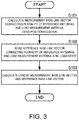
Fig. 3 is a first flowchart of a method of measuring a load according to the first embodiment of the present disclosure. -
Fig. 4 is a flowchart of a calculation of the load. -
Fig. 5 is a second functional block diagram of the processor of the load measuring device according to the first embodiment of the present disclosure. -
Fig. 6 is a second flowchart of the method of measuring the load according to the first embodiment of the present disclosure. -
Fig. 7 is a flowchart of a method of calculating a reference attitude angle. -
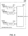
Fig. 8 is a functional block diagram of a load measuring device according to a second embodiment of the present disclosure. -
Fig. 9(A) is a plan view illustrating a layout of antennas of the load measuring device according to the second embodiment of the present disclosure, andFig. 9(B) is a side view illustrating the layout of the antennas. -
Fig. 10 is a functional block diagram of a load measuring device according to a third embodiment of the present disclosure. -
Fig. 11 is a side view illustrating a layout of antennas of the load measuring device according to the third embodiment of the present disclosure. - A load calculating device, a method of calculating a load, and a load calculating program according to a first embodiment of the present disclosure will be described with reference to the drawings.
-
Fig. 1(A) is a functional block diagram of a load measuring device according to a first embodiment of the present disclosure, andFig. 1(B) is a functional block diagram of a processor.Fig. 2(A) is a plan view illustrating a layout of antennas of the load measuring device according to the first embodiment of the present disclosure, andFig. 2(B) is a side view illustrating the layout of the antennas. - As illustrated in
Fig. 1(A) , aload measuring device 20 includesantennas receivers processor 220. As illustrated inFig. 1(B) , theprocessor 220 may include a measurement base-line vector calculatingmodule 221, a load calculatingmodule 222, and a reference base-line vector memory 223. Thereceivers processor 220 may be implemented by a storage device where a program for executing functions for the components is stored, and an arithmetic operation element (a CPU etc.) which executes the program stored in the storage device. - As illustrated in
Figs. 2(A) and 2(B) , theantennas hull 100 where positioning signals can be received. - The
antenna 204 is disposed at a measurement position of the load in thehull 100. The load on thehull 100 is, for example, at least one of a deflection and a strain of thehull 100. Theantennas hull 100 where a deformation does not easily occur. Although the position of thehull 100 where the deformation does not easily occur is desirable to be a position where the deformation does not absolutely easily occur, it may be at least a position where the deformation does not easily occur relatively as compared with the measurement position of the load. Theantennas antenna 204 may correspond to a "load measurement antenna" of the present disclosure. Note that, the layout illustrated in this embodiment is one example, and when measuring a load by a deformation of a bow, for example, the load measurement antenna may be disposed at the bow, and the plurality of reference antennas may be disposed at different positions from the bow of the hull. That is, the reference antenna may be disposed at a different position from a load measurement position of the hull. - The
antennas - For example, in the example of
Figs. 2(A) and 2(B) , theantenna 204 may be disposed at an intermediate position of thehull 100 in the direction in which abow 101 and astern 102 are connected. Theantennas control room 110 near thestern 102 of thehull 100, and theantenna 203 may be disposed at a position near thebow 101 of thehull 100. - In more detail, a hull coordinate system (XB, YB, ZB) may be defined as follows. The XB-direction may be parallel to a heading line of the
hull 100, and may be a direction toward thebow 101 from thestern 102. The YB-direction may be perpendicular to the heading line (XB-direction), and may be a direction toward the starboard from the port side. ZB may be perpendicular to the heading line (XB-direction) and the YB-direction, and may be a direction toward the ship's bottom side from the deck side. - In the XB-direction of the hull coordinate system, the
antenna 201 and theantenna 202 may be disposed at positions different from theantenna 203. In the YB-direction of the hull coordinate system, theantenna 201, theantenna 202, and theantenna 203 may be disposed at different positions. In the hull coordinate system ZB, theantenna 201 and theantenna 202 may be disposed at different positions from theantenna 203. In the XB-direction and the YB-direction of the hull coordinate system, theantenna 204 may be disposed at a different position from theantenna 201, theantenna 202, and theantenna 203. - A line which connects the
antenna 201 and theantenna 202 may be set as a base line BL12, a line which connects theantenna 202 and theantenna 203 may be set as a base line BL23, and a line which connects theantenna 203 and theantenna 201 may be set as a base line BL31. Moreover, a line which connects theantenna 201 and theantenna 204 may be set as a base line BL14, a line which connects theantenna 202 and theantenna 204 may be set as a base line BL24, and a line which connects theantenna 203 and theantenna 204 may be set as a base line BL34. - By arranging the
antennas - The
antennas receivers - The
receiver 211 may acquire and track the positioning signal received by theantenna 201, and measure a code phase and a carrier phase. Thereceiver 212 may acquire and track the positioning signal received by theantenna 202, and measure a code phase and a carrier phase. Thereceiver 213 may acquire and track the positioning signal received by theantenna 203, and measure a code phase and a carrier phase. Thereceiver 214 may acquire and track the positioning signal received by theantenna 204, and measure a code phase and a carrier phase. - Each of the
receivers receivers processor 220 along with a measured time. Note that thereceivers processor 220, or may output to theprocessor 220 code pseudo ranges acquired from the code phases or positioning results by the code pseudo ranges. - The
processor 220 may include the measurement base-linevector calculating module 221, theload calculating module 222, and the reference base-line vector memory 223. - The measurement base-line
vector calculating module 221 may calculate a measurement base-line vector by a known method based on carrier phase differences between the carrier phases inputted from thereceivers antenna 201 and theantenna 204, a measurement base-line vector XXn24 may be a base-line vector corresponding to the base line BL24 which connects theantenna 202 and theantenna 204, and a measurement base-line vector XXn34 may be a base-line vector corresponding to the base line BL34 which connects theantenna 203 and theantenna 204. These measurement base-line vectors XXn14, XXn24, and XXn34 may be calculated in a NED coordinate system (local tangent plane coordinate system). - Moreover, these measurement base-line vectors XXn14, XXn24, and XXn34 may be sequentially calculated over time at a time interval corresponding to the measurement cycle of the carrier phase. Therefore, according to a state of the load on the
hull 100, the measurement base-line vectors XXn14, XXn24, and XXn34 may be determined. - The measurement base-line
vector calculating module 221 may output the measurement base-line vectors XXn14, XXn24, and XXn34 to theload calculating module 222. - The reference base-
line vector memory 223 may store reference base-line vectors XXbo14, XXbo24, and XXbo34. The reference base-line vector XXbo14 may correspond to the base line BL14 same as the measurement base-line vector XXn14, the reference base-line vector XXbo24 may correspond to the base line BL24 same as the measurement base-line vector XXn24, and the reference base-line vector XXbo34 may correspond to the base line BL34 same as the measurement base-line vector XXn34. - The reference base-line vectors XXbo14, XXbo24, and XXbo34 may be base-line vectors according to the load, in more detail, a state of the
hull 100 before the load to be measured this time is applied. The reference base-line vectors XXbo14, XXbo24, and XXbo34 may be set in the hull coordinate system, and may be set beforehand based on designed dimensions of thehull 100 and various kinds of measurements of thehull 100. - The
load calculating module 222 may calculate the load based on a comparison result between the measurement base-line vector XXn14 and the reference base-line vector XXbo14, a comparison result between the measurement base-line vector XXn24 and the reference base-line vector XXbo24, and a comparison result between the measurement base-line vector XXn34 and the reference base-line vector XXbo34. - Here, the coordinate system may differ between the measurement base-line vector and the reference base-line vector. However, if these coordinate systems are made in agreement with each other by using a method etc. described below, or these coordinate systems become in agreement with each other (when the bow direction is the same as the north direction), the
load calculating module 222 can calculate the comparison result between the measurement base-line vector and the reference base-line vector. Further, theload calculating module 222 can calculate the comparison result between the measurement base-line vector and the reference base-line vector by storing all the patterns in the NED coordinate system, of the reference base-line vectors stored in the reference base-line vector memory 223 so that these coordinate systems are in agreement with each other. - In detail, the
load calculating module 222 may calculate a displacement "u" in the XB-direction, a displacement "v" in the YB-direction, and a displacement "w" in the ZB direction, at the position of theantenna 204 based on each comparison result. - For example, the
load calculating module 222 calculates differences between components of the measurement base-line vector XXn14 and the reference base-line vector XXbo14 as displacements u1, v1, and w1, differences between components of the measurement base-line vector XXn24 and the reference base-line vector XXbo24 as displacements u2, v2, and w2, and differences between components of the measurement base-line vector XXn34 and the reference base-line vector XXbo34 as displacements u3, v3, and w3. Theload calculating module 222 may calculate a weighted average of the displacements u1, u2, and u3 as the displacement u, a weighted average of the displacements v1, v2, and v3 as the displacement v, and a weighted average of the displacements w1, w2, and w3 as the displacement w. Here, the weights of the average processing may be determined based on an error variance which changes according to the number of positioning satellites, a satellite layout (DOP: Dilution of Precision), etc. used for the calculation of the displacements. - Note that, although in this embodiment the displacements u, v, and w are calculated based on the three comparison results between the measurement base-line vectors and the reference base-line vectors, the displacements u, v, and w may be calculated based on a comparison result between the reference base-line vector and at least one of the measurement base-line vectors.
- The
load calculating module 222 may use the displacement w in the ZB direction as a deflection δz. - The
load calculating module 222 may calculate a normal strain εx in the XB-direction by using the following formula based on the displacement u in the XB-direction.
load calculating module 222 may calculate a shearing strain yxy in the XB-YB plane by using the following formula based on the displacement u in the XB-direction and the displacement v in the YB-direction.
load calculating module 222 may calculate a deflection angle θ by using the following formula based on the displacement w in the ZB direction.
load measuring device 20 can calculate the load, such as the deflection, the strain, etc., which occurs in thehull 100, with a simple configuration using the positioning signal. Moreover, the load can be calculated with high precision by using the carrier phases of the positioning signals. - Although in the above description the processing of the
processor 220 is executed individually for each of the functional parts, the method and program of the load measurement executed by theprocessor 220 may follow the following flowchart. -
Fig. 3 is a first flowchart of the method of measuring the load according to the first embodiment of the present disclosure.Fig. 4 is a flowchart of the calculation of the load. - As illustrated in
Fig. 3 , theprocessor 220 may calculate the measurement base-line vectors XXn14, XXn24, and XXn34 which connect the plurality of reference antennas (theantennas processor 220 may calculate the measurement base-line vectors XXn14, XXn24, and XXn34 based on the carrier phase differences of the positioning signals between the antennas. - Next, the
processor 220 may read the reference base-line vectors XXbo14, XXbo24, and XXbo34 which connect the plurality of reference antennas (theantennas - Next, the
processor 220 may calculate the load by the method described above based on the measurement base-line vectors XXn14, XXn24, and XXn34, and the reference base-line vectors XXbo14, XXbo24 and XXbo34 (S103). - In detail, as illustrated in
Fig. 4 , theprocessor 220 may calculate the differences between the measurement base-line vectors XXn14, XXn24, and XXn34 and the reference base-line vectors XXbo14, XXbo24 and XXbo34 for every component of the hull coordinate system (XB, YB, ZB) (S241). - As described above, the
processor 220 may calculate the deflection δz based on the ZB component (S242). As described above, theprocessor 220 may calculate the normal strain εx based on the XB component, and calculate the shearing strain yxy based on the XB component and the YB component (S243). - In the description, the coordinate system of the measurement base-line vectors XXn14, XXn24, and XXn34 and the coordinate system of the reference base-line vectors XXbo14, XXbo24, and XXbo34 may become in agreement with each other, or can simply be made into agreement with each other. However, the following configuration and method may be used as one example of the concrete method of making the coordinate systems in agreement with each other.
-
Fig. 5 is a functional block diagram of the processor of the load measuring device in a mode in which the measurement base-line vector is in the NED coordinate system and the reference base-line vector is in the hull coordinate system. - As illustrated in
Fig. 5 , aprocessor 220A may include the measurement base-linevector calculating module 221, aload calculating module 222A, a reference base-line vector memory 223A, and a reference attitudeangle calculating module 224. The measurement base-linevector calculating module 221 may be similar to the measurement base-linevector calculating module 221 illustrated inFig. 1(B) , and it may calculate the measurement base-line vectors XXn14, XXn24, and XXn34 of the NED coordinate system, and output them to theload calculating module 222A. - The reference base-
line vector memory 223A may store the reference base-line vectors XXbo14, XXbo24, and XXbo34 of the hull coordinate system, similar to the reference base-line vector memory 223. Further, the reference base-line vector memory 223A may store reference base-line vectors XXbo12, XXbo23, and XXbo31. The reference base-line vector XXbo12 may correspond to the base line BL12 ofFig. 2 , the reference base-line vector XXbo23 may correspond to the base line BL23 ofFig. 2 , and the reference base-line vector XXbo31 may correspond to the base line BL31 ofFig. 2 . - The reference base-line vectors XXbo12, XXbo23, and XXbo31 may be the base-line vectors according to the load, in more detail, the state of the
hull 100 before the load to be measured this time is applied. The reference base-line vectors XXbo12, XXbo23, and XXbo31 may be set in the hull coordinate system, and may be set beforehand based on the designed dimensions of thehull 100 and various kinds of measurements of thehull 100. - The carrier phases may be inputted into the reference attitude
angle calculating module 224 from thereceivers angle calculating module 224 may calculate the carrier phase differences between theantennas receivers angle calculating module 224 may calculate base-line vectors XXn12, XXn23, and XXn31 for the calculation of the attitude angle by using a known method based on the carrier phase differences. The base-line vector XXn12 for the calculation of the attitude angle may be the base-line vector corresponding to the base line BL12 which connects theantenna 201 and theantenna 202. The base-line vector XXn23 for the calculation of the attitude angle may be the base-line vector corresponding to the base line BL23 which connects theantenna 202 and theantenna 203. The base-line vector XXn31 for the calculation of the attitude angle may be the base-line vector corresponding to the base line BL31 which connects theantenna 203 and theantenna 201. The base-line vectors XXn12, XXn23, and XXn31 for the calculation of the attitude angle may be calculated in the NED coordinate system. - The reference attitude
angle calculating module 224 may calculate reference attitude angles (ϕs, θs, ψs) based on the base-line vectors XXn12, XXn23, XXn31 for the calculation of the attitude angle and the reference base-line vectors XXbo12, XXbo23 and XXbo31. - Roughly, one base-line vector for the calculation of the attitude angle comprised of the base-line vectors XXn12, XXn23, and XXn31 for the calculation of the attitude angle is set as XXns, and one reference base-line vector comprised of the reference base-line vectors XXbo12, XXbo23 XXbo31 is set as XXbs. Moreover, a conversion matrix for converting the hull coordinate system into the NED coordinate system is set as Cb n. The conversion matrix Cb n can be set by the reference attitude angles (ϕs, θs, ψs) using a known coordinates converting formula between the three-dimensional rectangular coordinates.
- In this case, the following formula may be established.

- Therefore, the reference attitude
angle calculating module 224 may substitute the base-line vector XXns and the reference base-line vector XXbs for the calculation of the attitude angle into Formula A to calculate each component of the conversion matrix Cb n, and calculate the reference attitude angles (ϕs, θs, ψs). - The reference attitude
angle calculating module 224 may output the reference attitude angles (ϕs, θs, ψs) or the conversion matrix Cb n set by the reference attitude angles (ϕs, θs, ψs) to theload calculating module 222A. - The
load calculating module 222A may calculate the load based on the measurement base-line vectors XXn14, XXn24, and XXn34 of the NED coordinate system, the reference base-line vectors XXbo14, XXbo24, XXbo34 of the hull coordinate system, and the reference attitude angles (ϕs, θs, ψs) or the conversion matrix Cb n. That is, theload calculating module 222A may calculate the load based on base-line vectors XXnb14, XXnb24, and XXnb34 obtained by converting the measurement base-line vectors XXn14, XXn24, and XXn34 of the NED coordinate system into the hull coordinate system by the conversion matrix Cb n, and the reference base-line vectors XXbo14, XXbo24, and XXbo34 of the hull coordinate system. The method of calculating each load (the deflection δz, the normal strain εx, the shearing strain yxy, and the deflection angle θ) is described above, and, therefore, the description is omitted. - Thus, by using the configuration illustrated in
Fig. 5 , the measurement base-line vectors XXn14, XXn24, and XXn34 obtained in the NED coordinate system and the reference base-line vectors XXbo14, XXbo24, and XXbo34 of the hull coordinate system can be compared with each other in the hull coordinate system, and the load can be calculated. - Although in the above description the processing of the
processor 220A is executed individually by each functional part, the method and program of the load measurement which are executed by theprocessor 220A may follow the following flowchart. -
Fig. 6 is a second flowchart of the method of measuring the load according to the first embodiment of the present disclosure.Fig. 7 is a flowchart of the calculation of the reference attitude angle. - As illustrated in
Fig. 6 , theprocessor 220A may calculate the reference attitude angles (ϕs, θs, ψs) as described above based on the positioning signals received by the plurality of reference antennas (theantennas - In more detail, as illustrated in
Fig. 7 , theprocessor 220A may use the carrier phase differences between the antennas of the positioning signals received by the plurality of reference antennas (theantennas antennas processor 220A may read the reference base-line vectors XXbo12, XXbo23, and XXbo31 which connect the plurality of reference antennas (theantennas processor 220A may calculate, by the method described above, the reference attitude angles (ϕs, θs, ψs) based on the base-line vectors XXn12, XXn23, XXn31 for the calculation of the attitude angle, and the reference base-line vectors XXbo12, XXbo23 and XXbo31 (S213). - As illustrated in
Fig. 6 , theprocessor 220A may calculate the measurement base-line vectors XXn14, XXn24, and XXn34 which connect the plurality of reference antennas (theantennas processor 220A may calculate the measurement base-line vectors XXn14, XXn24, and XXn34 based on the carrier phase differences of the positioning signals between the antennas. - Next, the
processor 220A may read the reference base-line vectors XXbo14, XXbo24, and XXbo34 which connect the plurality of reference antennas (theantennas - Next, the
processor 220A may calculate the load by the method described above based on the measurement base-line vectors XXn14, XXn24, and XXn34, the reference base-line vectors XXbo14, XXbo24 and XXbo34, and the reference attitude angles (ϕs, θs, ψs) (S204). - Next, a load calculating device, a method of calculating a load, and a load calculating program according to a second embodiment will be described with reference to the drawings.
-
Fig. 8 is a functional block diagram of the load measuring device according to the second embodiment of the present disclosure.Fig. 9(A) is a plan view illustrating a layout of the antennas of the load measuring device according to the second embodiment of the present disclosure, andFig. 9(B) is a side view illustrating the layout of the antennas. - As illustrated in
Figs. 8 ,9(A), and 9(B) , aload measuring device 20B according to the second embodiment may differ in the number of placed antennas and the layout pattern in thehull 100, from theload measuring device 20 according to the first embodiment. Moreover, theload measuring device 20B may perform processing according to the differences in the number of placed antennas and the layout pattern. Note that the functional blocks of theprocessor 220 may be similar to those ofFig. 5 , but the processings in each functional part may differ. - As illustrated in
Fig. 8 , theload measuring device 20B may includeantennas receivers processor 220. Theantenna 201B may output a received positioning signal to thereceiver 211, theantenna 202B may output a received positioning signal to thereceiver 212, and theantenna 204B may output the received positioning signal to thereceiver 214. - As illustrated in
Figs. 9(A) and 9(B) , theantennas hull 100 where they can receive the positioning signals. - The
antenna 204B may be disposed at a measurement position of the load in thehull 100. Theantennas hull 100 where deformations do not easily occur. Theantennas antenna 204B corresponds to the "load measurement antenna" of the present disclosure. - The
antennas hull 100, in other words, the direction which connects thebow 101 and the stern 102. Theantenna 204B may be disposed on a straight line which passes through theantenna 201B and theantenna 202B. - For example, in the example of
Figs. 9(A) and 9(B) , theantenna 204B may be disposed at an intermediate position in the direction in which thebow 101 and the stern 102 are connected to each other in thehull 100. Theantenna 201B may be disposed at a position near the stern 102 of thehull 100, and theantenna 202B may be disposed at a position near thebow 101 of thehull 100. Theantennas hull 100. - In this configuration, a base-line BL12B which connects the
antenna 201B and theantenna 202B, a base line BL14B which connects theantenna 201B and theantenna 204B, and a base line BL24B which connects theantenna 202B and theantenna 204B may be parallel to the heading line. Therefore, as for the reference base-line vector XXbo12 which connects theantenna 201B and theantenna 202B, the YB component and the ZB component may be 0, and may only have the XB component. - As described above, the
processor 220 may calculate a base-line vector XXn12 for the calculation of the attitude angle based on the carrier phase difference between the positioning signals received by theantenna 201B and theantenna 202B. As described above, theprocessor 220 may calculate a pitch angle θs and a heading angle ϕs in the reference attitude angle based on the base-line vector XXn12 for the attitude angle calculation, and the reference base-line vector XXbo12. - The
processor 220 may suitably set a roll angle ψs in the reference attitude angle. For example, theprocessor 220 sets the roll angle ψs as 0. Alternatively, if each of theantennas processor 220 may calculate and set the roll angle ψs by using a known attitude angle calculation method using the plurality of proximate antennas. - Similarly to the method illustrated in the first embodiment, the
processor 220 may calculate a measurement base-line vector XXn14 of the NED coordinate system which connects theantenna 201B and theantenna 204B, and a measurement base-line vector XXn24 of the NED coordinate system which connects theantenna 202B and theantenna 204B. Moreover, similarly to the method illustrated in the first embodiment, theprocessor 220 may store the reference base-line vector XXbo14 of the hull coordinate system which connects theantenna 201B and theantenna 204B, and the reference base-line vector XXbo24 of the hull coordinate system which connects theantenna 202B and theantenna 204B. - The
processor 220 may apply a similar method to the first embodiment based on the measurement base-line vectors XXn14 and XXn24 of the NED coordinate system, the reference base-line vectors XXbo14 and XXbo24 of the hull coordinate system, and the reference attitude angles (ϕs, θs, ψs) or the conversion matrix Cb n determined by the reference attitude angles, and may calculate a deflection δz at the load. - By such a configuration, the number of reference antennas can be reduced to two, and, therefore, the configuration for measuring the deflection can be simplified.
- Next, a load calculating device, a method of calculating a load, and a load calculating program according to a third embodiment are described with reference to the drawings.
-
Fig. 10 is a functional block diagram of the load measuring device according to the third embodiment of the present disclosure.Fig. 11 is a side view illustrating a layout of the antennas of the load measuring device according to the third embodiment of the present disclosure. - As illustrated in
Figs. 10 and11 , the load measuring device according to the third embodiment may differ in the configuration of aprocessor 220C from theload measuring device 20 according to the first embodiment. Other configurations of the load measuring device according to the third embodiment may be similar to those of theload measuring device 20, and, therefore, the description of the same parts is omitted. - The
processor 220C may include a normalvector calculating module 225, a load measurement antennaposition calculating module 226, and aload calculating module 227. Code phases and carrier phases may be inputted into the normalvector calculating module 225 from thereceivers position calculating module 226 from thereceiver 214. - The normal
vector calculating module 225 may calculate relative position coordinates P1 of theantenna 201, relative position coordinates P2 of theantenna 202, and relative position coordinates P3 of theantenna 203 with respect to a reference point of thehull 100 based on the code phases or the carrier phases inputted from thereceivers hull 100, and, for example, may be the position of theantenna 201, the position of theantenna 202, or the position of theantenna 203. - The normal
vector calculating module 225 may calculate a normal vector NV123 of a reference plane PL123 including theantennas vector calculating module 225 may make the three components of the normal vector NV123 into unit vectors by dividing the three components by a respective absolute value. The normalvector calculating module 225 may output the unit vectors of the three components of the normal vector NV123 to theload calculating module 227. - The load measurement antenna
position calculating module 226 may calculate a relative position coordinates P4 of theantenna 204 with respect to the reference point of thehull 100 based on the code phase or the carrier phase inputted from thereceiver 214. The reference point with respect to the relative position coordinates P4 of theantenna 204 may be the same as the reference points of the relative position coordinates P1, P2, and P3 of theantennas position calculating module 226 may output the relative position coordinates P4 to theload calculating module 227. - The
load calculating module 227 may calculate a distance between the reference plane PL123 including theantennas antenna 204 by performing an inner product operation of the normal vector NV123 and the relative position coordinates P4. This distance may depend on the deflection caused by the load on thehull 100. - Therefore, by performing such a configuration and processing, the distance between the reference plane PL123 of which the position is fixed and the
antenna 204 of which the position changes by the load can be calculated, and this distance can be used as the load index value. - Moreover, by using the configuration and the method of this embodiment, it may not be necessary to perform the coordinates conversion based on the reference attitude angle as illustrated in the first and second embodiments. Therefore, the load on the
hull 100 can be calculated by the simple processing. Note that, a load index value δzz corresponding to the deflection of thehull 100 can be calculated based on the relative coordinates of the antennas with respect to the reference point of the hull, i.e., the antenna layout positions and the distance. - Although in the above description the processing of the
processor 220C is executed individually by each functional part, the method and program of the load measurement which are executed by theprocessor 220C may follow the following flowchart. Fig. 12 is a flowchart of the method of measuring the load according to the third embodiment of the present disclosure. - As illustrated in Fig. 12, the
processor 220C may calculate the relative position coordinates P1, P2, and P3 of the three reference antennas (theantennas - The
processor 220C may calculate the normal vector NV123 in the reference plane including the three reference antennas (theantennas - The
processor 220C may calculate the relative position coordinates P4 of the load measurement antenna (the antenna 204) with respect to the specific reference point based on the positioning signal (S303). - The
processor 220C may calculate the load index value δzz in the direction described above based on the normal vector 123 and the relative position coordinates P4 (S304). - Note that, although in this embodiment one reference plane is set, a plurality of reference planes may be set, and the load may be calculated based on the positions of the plurality of reference planes and the
antenna 204. In this case, four or more reference antennas may be installed according to the number of set reference planes. - Moreover, although in the above description the ship is described as the example, the present disclosure is also applicable to large-sized movable bodies, such as aircrafts, and large-sized structures, in which the deflection, and the strain occur. However, the configuration and processing of the present disclosure are effective in those of which the position changes, such as the large-sized movable bodies.
- Moreover, the load can be calculated by simple configuration and processing using a configuration and processing comprised of the following concept, without using only the configuration and processing described above. A load measurement antenna may be disposed at a position of the hull for measuring the load, and a plurality of reference antennas may be disposed at a plurality of positions of the hull where deformations do not occur easily as compared with the position for measuring the load. The positioning signal may be received by each of the load measurement antenna and the plurality of reference antennas. A processor may calculate an index depending on changes in relative positions of the load measurement antenna with respect to the plurality of reference antennas based on the positioning signals, and may calculate the load based on the index.
-
- 20, 20B: Load Measuring Device
- 100: Hull
- 101: Bow
- 102: Stern
- 110: Control Room
- 123: Normal Vector
- 201, 201B, 202, 202B, 203, 204, 204B: Antenna
- 211, 212, 213, 214: Receiver
- 220, 220A, 220C: Processor
- 221: Measurement Base-line Vector Calculating Module
- 222, 222A, 227: Load Calculating Module
- 223 223A: Reference Base-line Vector Memory
- 224: Reference Attitude Angle Calculating Module
- 225: Normal Vector Calculating Module
- 226: Load Measurement Antenna Position Calculating Module
- BL12, BL12B, BL14, BL14B, BL23, BL24, BL24B, BL31, BL34: Base Line
- NV123: Normal Vector
- P1, P2, P3, P4: Relative Position Coordinates
- PL123: Reference Plane
- XXbo12, XXbo14, XXbo23, XXbo24, XXbo31, XXbo34, XXbs: Reference
- Base-line Vector
- XXn14, XXn24, XXn34: Measurement Base-line Vector
- XXn12, XXn23, XXn31: Base-line Vector for Calculation of Attitude Angle
- XXnb14: Base-line Vector
- XXns: Base-line Vector
Claims (17)
- A load measuring device, comprising:a load measurement antenna disposed at a load measuring position of a structure;a plurality of reference antennas disposed at positions of the structure different from the load measuring position; anda processor configured to calculate a load based on changes in relative positions of the load measurement antenna with respect to the plurality of reference antennas by using positioning signals received by the load measurement antenna and the plurality of reference antennas.
- The load measuring device of claim 1, wherein the processor includes:a measurement base-line vector calculating module configured to calculate measurement base-line vectors connecting the load measurement antenna and the plurality of reference antennas by using carrier phases of the positioning signals received by the load measurement antenna and the plurality of reference antennas; anda load calculating module configured to calculate the load based on reference base-line vectors connecting the load measurement antenna and the plurality of reference antennas in a state before the load is applied to the structure, and at least one of the measurement base-line vectors.
- The load measuring device of claim 2, comprising a reference attitude angle calculating module configured to calculate a reference attitude angle of the structure based on the carrier phases of the positioning signals received by the plurality of reference antennas,
wherein the load calculating module defines and stores the reference base-line vectors in the state before the load is applied to the structure in a coordinate system peculiar to the structure, and calculates the load based on the reference base-line vectors, the reference attitude angle, and the measurement base-line vectors. - The load measuring device of claim 3, wherein the load calculating module calculates a coordinates conversion matrix for the coordinate system peculiar to the structure and a coordinate system using the positioning signals based on the reference attitude angle, and calculates the load based on the coordinates conversion matrix by coinciding the coordinates of the reference base-line vectors and the coordinates of the measurement base-line vectors.
- The load measuring device of claim 3 or 4, wherein the reference attitude angle calculating module calculates a first base-line vector of a coordinate system using the positioning signals connecting the plurality of reference antennas based on the carrier phases of the positioning signals received by the plurality of reference antennas, and calculates the reference attitude angle based on a second base-line vector defined beforehand of the coordinate system peculiar to the structure, and the first base-line vector.
- The load measuring device of any one of claims 1 to 5, wherein the reference antennas are disposed at least at three positions that are not lined up on a straight line, and the load measurement antenna is disposed at a different position from the base-lines connecting the respective reference antennas.
- The load measuring device of any one of claims 1 to 5, wherein the number of reference antennas is two, and the two reference antennas are disposed in parallel to a reference line of the structure, and
wherein the load measurement antenna is disposed on a straight line connecting the two reference antennas. - The load measuring device of claim 1, wherein the plurality of reference antennas are reference antennas installed at least at three positions, and
wherein the processor includes:a normal vector calculating module configured to calculate a normal vector of a plane including the reference antennas disposed at least at the three positions;a load measurement antenna position calculating module configured to calculate a layout position of the load measurement antenna based on the positioning signal received by the load measurement antenna; anda load calculating module configured to calculate the load based on the normal vector, and the layout position of the load measurement antenna. - The load measuring device of claim 8, wherein the normal vector calculating module calculates the layout position of each of the reference antennas disposed at least at the three positions based on the positioning signals received by the reference antennas disposed at least at the three positions, and calculates the normal vector of a plane including the reference antennas disposed at least at the three positions.
- The load measuring device of any one of claims 1 to 9, wherein the load is a deflection or strain of the structure.
- The load measuring device of any one of claims 1 to 10, wherein the structure is a hull.
- A method of measuring a load, comprising the steps of:receiving positioning signals by a load measurement antenna disposed at a load measuring position of a structure and a plurality of reference antennas disposed at positions different from the load measuring position; andcalculating the load based on changes in relative positions of the load measurement antenna with respect to the plurality of reference antennas by using the positioning signals.
- The method of claim 12, wherein the calculating the load includes:calculating measurement base-line vectors connecting the load measurement antenna and the plurality of reference antennas by using carrier phases of the positioning signals received by the load measurement antenna and the plurality of reference antennas; andcalculating the load based on reference base-line vectors connecting the load measurement antenna and the plurality of reference antennas in a state before the load is applied to the structure, and at least one of the measurement base-line vectors.
- The method of claim 12, wherein the plurality of reference antennas are reference antennas installed at least at three positions, and
wherein the calculating the load includes:calculating a normal vector of a plane including the reference antennas disposed at least at the three positions;calculating a layout position of the load measurement antenna based on the positioning signal received by the load measurement antenna; andcalculating the load based on the normal vector, and the layout position of the load measurement antenna. - A load measurement program configured to cause a processor to execute processing comprising:receiving positioning signals by a load measurement antenna disposed at a load measuring position of a structure and a plurality of reference antennas disposed at positions different from the load measuring position; andcalculating a load based on changes in relative positions of the load measurement antenna with respect to the plurality of reference antennas by using the positioning signals.
- The load measurement program of claim 15, wherein the calculating the load includes:calculating measurement base-line vectors connecting the load measurement antenna and the plurality of reference antennas by using carrier phases of the positioning signals received by the load measurement antenna and the plurality of reference antennas; andcalculating the load based on reference base-line vectors connecting the load measurement antenna and the plurality of reference antennas in a state before the load is applied to the structure, and at least one of the measurement base-line vectors.
- The load measurement program of claim 15, wherein the calculating the load includes:calculating a normal vector of a plane including the reference antennas disposed at least at three positions as a plurality of reference antennas;calculating a layout position of the load measurement antenna based on the positioning signal received by the load measurement antenna; andcalculating the load based on the normal vector, and the layout position of the load measurement antenna.
Applications Claiming Priority (2)
| Application Number | Priority Date | Filing Date | Title |
|---|---|---|---|
| JP2017081713 | 2017-04-18 | ||
| PCT/JP2018/012368 WO2018193797A1 (en) | 2017-04-18 | 2018-03-27 | Load measuring device, load measuring method, and load measuring program |
Publications (2)
| Publication Number | Publication Date |
|---|---|
| EP3614178A1 true EP3614178A1 (en) | 2020-02-26 |
| EP3614178A4 EP3614178A4 (en) | 2021-04-07 |
Family
ID=63856680
Family Applications (1)
| Application Number | Title | Priority Date | Filing Date |
|---|---|---|---|
| EP18787763.4A Withdrawn EP3614178A4 (en) | 2017-04-18 | 2018-03-27 | Load measuring device, load measuring method, and load measuring program |
Country Status (4)
| Country | Link |
|---|---|
| EP (1) | EP3614178A4 (en) |
| JP (1) | JP6928646B2 (en) |
| CN (1) | CN110446945B (en) |
| WO (1) | WO2018193797A1 (en) |
Families Citing this family (2)
| Publication number | Priority date | Publication date | Assignee | Title |
|---|---|---|---|---|
| JP7432478B2 (en) * | 2020-10-01 | 2024-02-16 | 株式会社フジタ | Position conversion method, program and moving device |
| CN119779207B (en) * | 2024-11-29 | 2025-10-10 | 中国电子科技集团公司第五十四研究所 | Homologous multichannel pseudolite deformation monitoring system under GNSS refusing environment |
Family Cites Families (7)
| Publication number | Priority date | Publication date | Assignee | Title |
|---|---|---|---|---|
| JP4563157B2 (en) * | 2004-12-01 | 2010-10-13 | 古野電気株式会社 | Object orientation and orientation detection device |
| JP5340543B2 (en) * | 2007-01-18 | 2013-11-13 | 前田建設工業株式会社 | System for judging the soundness of temporary structures |
| JP2009294009A (en) * | 2008-06-04 | 2009-12-17 | Mitsubishi Electric Corp | Navigation apparatus and attitude angle calculation method and attitude angle calculation program for navigation apparatus |
| JP5430172B2 (en) * | 2009-02-20 | 2014-02-26 | 三菱電機株式会社 | Direction calculation apparatus, direction calculation method of direction calculation apparatus, and direction calculation program |
| JP6321914B2 (en) * | 2013-04-04 | 2018-05-09 | 古野電気株式会社 | Mobile body information calculation device, mobile body information acquisition device, mobile body, mobile body information calculation method, mobile body information acquisition method, mobile body information calculation program, and mobile body information acquisition program |
| CN105940320B (en) * | 2014-02-21 | 2020-01-07 | 古野电气株式会社 | Displacement detection device of structure, shared system of displacement of structure, displacement detection method of structure, and displacement detection system of structure |
| US10473789B1 (en) * | 2015-04-13 | 2019-11-12 | Lockheed Martin Corporation | Real-time ship position error compensation system and method |
-
2018
- 2018-03-27 WO PCT/JP2018/012368 patent/WO2018193797A1/en not_active Ceased
- 2018-03-27 JP JP2019513282A patent/JP6928646B2/en active Active
- 2018-03-27 EP EP18787763.4A patent/EP3614178A4/en not_active Withdrawn
- 2018-03-27 CN CN201880019968.5A patent/CN110446945B/en active Active
Also Published As
| Publication number | Publication date |
|---|---|
| CN110446945B (en) | 2023-08-04 |
| WO2018193797A1 (en) | 2018-10-25 |
| EP3614178A4 (en) | 2021-04-07 |
| JPWO2018193797A1 (en) | 2020-05-28 |
| JP6928646B2 (en) | 2021-09-01 |
| CN110446945A (en) | 2019-11-12 |
Similar Documents
| Publication | Publication Date | Title |
|---|---|---|
| Mochalov et al. | Use of ring laser units for measurement of moving object deformations | |
| US5933110A (en) | Vessel attitude determination system and method | |
| CN105842724B (en) | A kind of ship auxiliary anchors alongside the shore method and system | |
| EP2706379A1 (en) | Method and system for providing integrity for hybrid attitude and true heading | |
| JP6470314B2 (en) | Attitude angle calculation device, attitude angle calculation method, and attitude angle calculation program | |
| JPWO2016104033A1 (en) | State calculation device, state calculation method, and state calculation program | |
| Zharkov et al. | Attitude determination using ambiguous GNSS phase measurements and absolute angular rate measurements | |
| EP3614178A1 (en) | Load measuring device, load measuring method, and load measuring program | |
| US10948292B2 (en) | Sensor error calculating device, attitude angle calculating apparatus, method of calculating sensor error and method of calculating attitude angle | |
| Giorgi | Attitude determination | |
| Yayla et al. | Accuracy benchmark of Galileo and EGNOS for Inland Waterways | |
| US20260078997A1 (en) | Hull structure monitoring system and monitoring method | |
| Li et al. | Adaptively robust filtering algorithm for maritime celestial navigation | |
| Wu et al. | Rapid in-motion heading alignment using time-differenced carrier phases from a single GNSS antenna and a low-grade IMU | |
| US6211821B1 (en) | Apparatus and method for determining pitch and azimuth from satellite signals | |
| JP7291775B2 (en) | MOVEMENT INFORMATION CALCULATION DEVICE AND MOVEMENT INFORMATION CALCULATION METHOD | |
| RU2643072C2 (en) | Method of high-accuracy determination of navigation elements of vessel movement | |
| JP2012202749A (en) | Orientation detection device | |
| RU2221728C1 (en) | Ship motion automatic control equipment | |
| RU2402035C1 (en) | Method of determining coordinates of refuelling aircraft and cone and device for realising said method | |
| RU2523670C1 (en) | Integrated inertial-satellite system of orientation and navigation for marine facilities | |
| JP4417812B2 (en) | Ship attitude angle measuring device | |
| Boudiba et al. | Functionally stable motion control of small autonomous aircraft | |
| Ueno | Use of GPS for a berthing guidance system | |
| RU2408917C1 (en) | Orientation system of communication station antenna |
Legal Events
| Date | Code | Title | Description |
|---|---|---|---|
| STAA | Information on the status of an ep patent application or granted ep patent |
Free format text: STATUS: THE INTERNATIONAL PUBLICATION HAS BEEN MADE |
|
| PUAI | Public reference made under article 153(3) epc to a published international application that has entered the european phase |
Free format text: ORIGINAL CODE: 0009012 |
|
| STAA | Information on the status of an ep patent application or granted ep patent |
Free format text: STATUS: REQUEST FOR EXAMINATION WAS MADE |
|
| 17P | Request for examination filed |
Effective date: 20191107 |
|
| AK | Designated contracting states |
Kind code of ref document: A1 Designated state(s): AL AT BE BG CH CY CZ DE DK EE ES FI FR GB GR HR HU IE IS IT LI LT LU LV MC MK MT NL NO PL PT RO RS SE SI SK SM TR |
|
| AX | Request for extension of the european patent |
Extension state: BA ME |
|
| DAV | Request for validation of the european patent (deleted) | ||
| DAX | Request for extension of the european patent (deleted) | ||
| RIC1 | Information provided on ipc code assigned before grant |
Ipc: G01L 1/00 20060101ALI20201127BHEP Ipc: B63B 49/00 20060101ALI20201127BHEP Ipc: B63B 79/10 20200101ALI20201127BHEP Ipc: G01S 19/14 20100101AFI20201127BHEP Ipc: G01S 19/54 20100101ALI20201127BHEP Ipc: G01B 21/32 20060101ALI20201127BHEP Ipc: B64F 5/60 20170101ALI20201127BHEP |
|
| A4 | Supplementary search report drawn up and despatched |
Effective date: 20210310 |
|
| RIC1 | Information provided on ipc code assigned before grant |
Ipc: G01S 19/14 20100101AFI20210303BHEP Ipc: B64F 5/60 20170101ALI20210303BHEP Ipc: B63B 49/00 20060101ALI20210303BHEP Ipc: G01L 1/00 20060101ALI20210303BHEP Ipc: B63B 79/10 20200101ALI20210303BHEP Ipc: G01B 21/32 20060101ALI20210303BHEP Ipc: G01S 19/54 20100101ALI20210303BHEP |
|
| STAA | Information on the status of an ep patent application or granted ep patent |
Free format text: STATUS: EXAMINATION IS IN PROGRESS |
|
| 17Q | First examination report despatched |
Effective date: 20231010 |
|
| STAA | Information on the status of an ep patent application or granted ep patent |
Free format text: STATUS: THE APPLICATION IS DEEMED TO BE WITHDRAWN |
|
| 18D | Application deemed to be withdrawn |
Effective date: 20240221 |