EP3614123A2 - Method and system for measuring viscosity in continuous flow field, and method and system for predicting flow rate or pressure drop of non-newtonian fluid in continuous flow field - Google Patents
Method and system for measuring viscosity in continuous flow field, and method and system for predicting flow rate or pressure drop of non-newtonian fluid in continuous flow field Download PDFInfo
- Publication number
- EP3614123A2 EP3614123A2 EP18783849.5A EP18783849A EP3614123A2 EP 3614123 A2 EP3614123 A2 EP 3614123A2 EP 18783849 A EP18783849 A EP 18783849A EP 3614123 A2 EP3614123 A2 EP 3614123A2
- Authority
- EP
- European Patent Office
- Prior art keywords
- rate
- flow
- flow field
- fluid
- energy dissipation
- Prior art date
- Legal status (The legal status is an assumption and is not a legal conclusion. Google has not performed a legal analysis and makes no representation as to the accuracy of the status listed.)
- Granted
Links
- 239000012530 fluid Substances 0.000 title claims abstract description 404
- 238000000034 method Methods 0.000 title claims abstract description 69
- 230000021715 photosynthesis, light harvesting Effects 0.000 claims description 193
- 238000009795 derivation Methods 0.000 claims description 24
- 238000005259 measurement Methods 0.000 claims description 23
- 238000004364 calculation method Methods 0.000 claims description 21
- 238000003860 storage Methods 0.000 claims description 19
- 238000005206 flow analysis Methods 0.000 claims description 12
- 238000009530 blood pressure measurement Methods 0.000 claims description 9
- 230000006399 behavior Effects 0.000 abstract description 45
- 230000006870 function Effects 0.000 description 16
- 238000000691 measurement method Methods 0.000 description 10
- 238000012545 processing Methods 0.000 description 10
- 238000002474 experimental method Methods 0.000 description 8
- 230000008569 process Effects 0.000 description 8
- 238000004088 simulation Methods 0.000 description 8
- 239000000243 solution Substances 0.000 description 8
- 230000003068 static effect Effects 0.000 description 6
- JVTIXNMXDLQEJE-UHFFFAOYSA-N 2-decanoyloxypropyl decanoate 2-octanoyloxypropyl octanoate Chemical compound C(CCCCCCC)(=O)OCC(C)OC(CCCCCCC)=O.C(=O)(CCCCCCCCC)OCC(C)OC(=O)CCCCCCCCC JVTIXNMXDLQEJE-UHFFFAOYSA-N 0.000 description 4
- 238000004458 analytical method Methods 0.000 description 4
- 229940075510 carbopol 981 Drugs 0.000 description 4
- 229920000642 polymer Polymers 0.000 description 4
- 238000004422 calculation algorithm Methods 0.000 description 3
- 230000008602 contraction Effects 0.000 description 2
- 238000000605 extraction Methods 0.000 description 2
- 238000001125 extrusion Methods 0.000 description 2
- 238000011065 in-situ storage Methods 0.000 description 2
- 238000010094 polymer processing Methods 0.000 description 2
- 238000011002 quantification Methods 0.000 description 2
- 238000010008 shearing Methods 0.000 description 2
- 239000007787 solid Substances 0.000 description 2
- 230000008859 change Effects 0.000 description 1
- 238000001311 chemical methods and process Methods 0.000 description 1
- 239000002537 cosmetic Substances 0.000 description 1
- 238000005553 drilling Methods 0.000 description 1
- 230000000694 effects Effects 0.000 description 1
- 239000012776 electronic material Substances 0.000 description 1
- 238000002347 injection Methods 0.000 description 1
- 239000007924 injection Substances 0.000 description 1
- 230000003993 interaction Effects 0.000 description 1
- 238000002156 mixing Methods 0.000 description 1
- 238000012986 modification Methods 0.000 description 1
- 230000004048 modification Effects 0.000 description 1
- 239000003973 paint Substances 0.000 description 1
- 239000002245 particle Substances 0.000 description 1
- 229920003023 plastic Polymers 0.000 description 1
- 239000002002 slurry Substances 0.000 description 1
- 239000000725 suspension Substances 0.000 description 1
- XLYOFNOQVPJJNP-UHFFFAOYSA-N water Substances O XLYOFNOQVPJJNP-UHFFFAOYSA-N 0.000 description 1
- 229920001285 xanthan gum Polymers 0.000 description 1
- 229940082509 xanthan gum Drugs 0.000 description 1
- 235000010493 xanthan gum Nutrition 0.000 description 1
- 239000000230 xanthan gum Substances 0.000 description 1
Images


Classifications
-
- G—PHYSICS
- G01—MEASURING; TESTING
- G01F—MEASURING VOLUME, VOLUME FLOW, MASS FLOW OR LIQUID LEVEL; METERING BY VOLUME
- G01F1/00—Measuring the volume flow or mass flow of fluid or fluent solid material wherein the fluid passes through a meter in a continuous flow
- G01F1/05—Measuring the volume flow or mass flow of fluid or fluent solid material wherein the fluid passes through a meter in a continuous flow by using mechanical effects
- G01F1/34—Measuring the volume flow or mass flow of fluid or fluent solid material wherein the fluid passes through a meter in a continuous flow by using mechanical effects by measuring pressure or differential pressure
-
- G—PHYSICS
- G01—MEASURING; TESTING
- G01N—INVESTIGATING OR ANALYSING MATERIALS BY DETERMINING THEIR CHEMICAL OR PHYSICAL PROPERTIES
- G01N11/00—Investigating flow properties of materials, e.g. viscosity, plasticity; Analysing materials by determining flow properties
- G01N11/02—Investigating flow properties of materials, e.g. viscosity, plasticity; Analysing materials by determining flow properties by measuring flow of the material
-
- G—PHYSICS
- G01—MEASURING; TESTING
- G01F—MEASURING VOLUME, VOLUME FLOW, MASS FLOW OR LIQUID LEVEL; METERING BY VOLUME
- G01F1/00—Measuring the volume flow or mass flow of fluid or fluent solid material wherein the fluid passes through a meter in a continuous flow
-
- G—PHYSICS
- G01—MEASURING; TESTING
- G01N—INVESTIGATING OR ANALYSING MATERIALS BY DETERMINING THEIR CHEMICAL OR PHYSICAL PROPERTIES
- G01N11/00—Investigating flow properties of materials, e.g. viscosity, plasticity; Analysing materials by determining flow properties
- G01N11/02—Investigating flow properties of materials, e.g. viscosity, plasticity; Analysing materials by determining flow properties by measuring flow of the material
- G01N11/04—Investigating flow properties of materials, e.g. viscosity, plasticity; Analysing materials by determining flow properties by measuring flow of the material through a restricted passage, e.g. tube, aperture
- G01N11/08—Investigating flow properties of materials, e.g. viscosity, plasticity; Analysing materials by determining flow properties by measuring flow of the material through a restricted passage, e.g. tube, aperture by measuring pressure required to produce a known flow
-
- G—PHYSICS
- G01—MEASURING; TESTING
- G01N—INVESTIGATING OR ANALYSING MATERIALS BY DETERMINING THEIR CHEMICAL OR PHYSICAL PROPERTIES
- G01N11/00—Investigating flow properties of materials, e.g. viscosity, plasticity; Analysing materials by determining flow properties
- G01N2011/0006—Calibrating, controlling or cleaning viscometers
-
- G—PHYSICS
- G01—MEASURING; TESTING
- G01N—INVESTIGATING OR ANALYSING MATERIALS BY DETERMINING THEIR CHEMICAL OR PHYSICAL PROPERTIES
- G01N11/00—Investigating flow properties of materials, e.g. viscosity, plasticity; Analysing materials by determining flow properties
- G01N2011/0026—Investigating specific flow properties of non-Newtonian fluids
Definitions
- the present disclosure relates to a viscosity measurement method and system for a continuous flow field, and a method and system for predicting a flow rate or pressure drop of non-Newtonian fluid in a continuous flow field.
- Rheologically complex fluid such as polymer melt and solution, particle suspension, slurry and droplet system exhibits a complex viscosity change such as shear-thinning and yield stress through a hydrodynamic interaction with a microstructure, and is applied to various processes such as a chemical process, polymer processing, electronic material (display and secondary battery) processing, food processing, cosmetics processing, paint processing, water treatment and oil drilling.
- a first method (i) may include putting the fluid between flat plates, applying a shearing force to one of the plates to measure a shear rate, and measuring the viscosity of the fluid through the relationship between the shearing force and the shear rate.
- a second method (ii) may include passing the fluid to a thin micro-tube with a simple circular or rectangular cross-section, and measuring the viscosity of the fluid using the relationship between pressure difference and flow rate.
- the Metzner-Otto method as a flow quantification method based on an energy dissipation rate, which is applied as a scaling concept and empirical access only in flows in existing limited mixers.
- the Metzner-Otto method has been based on the supposition that there is an average shear rate representing the entire flow fields in a mixing system, has defined such a correlation that the average shear rate is proportional to the velocity of an impeller, and has defined an effective shear rate and effective viscosity of non-Newtonian fluid flowing in a mixer based on the fact that Newtonian fluid and non-Newtonian fluid have the same energy dissipation rate.
- the present disclosure has been developed to apply a quantification method based on an energy dissipation rate, which is similar to the Metzner-Otto method, to all continuous flow fields with an inlet and outlet.
- Examples of the related art may include US Patent No. 6,412,337 .
- the Metzner-Otto concept has been expanded to measure viscosity in a static mixer.
- the related art is also based on the fact that Newtonian fluid and non-Newtonian fluid have the same energy dissipation rate.
- the related art is based on the supposition that a viscosity model of fluid is power-law fluid, and discloses "connecting two static mixers" to measure a pressure drop and a flow rate, in order to find two kinds of coefficients of the power-law fluid, i.e. a consistency index and a power-law index.
- the present disclosure can measure viscosity through only one on-site operation of measuring a pressure drop and a flow rate in a flow field of arbitrary geometry, without deciding a viscosity model in advance. Therefore, the present invention is different from the above-described related art, and may have a much wider application range. When the application range is wide, it may indicate that the present disclosure can treat various viscosity models of fluid, and be applied to any types of general flow fields as well as a static mixer.
- the relationships between flow rate and pressure drop which is referred to as die characteristics of an extrusion die used for polymer processing, serve as very important information for deciding a process condition and the like. Since the relationships between flow rate and pressure drop are different depending on the types and temperatures of polymers used for the process, the relationships between flow rate and pressure drop had to be calculated through separate experiments and analyses for respective fluids used in the process, which was very inconvenient.
- Various embodiments are directed to a method which can easily measure viscosity behaviors of fluid by calculating flow numbers in a continuous flow field of arbitrary geometry, and measuring only a flow rate and pressure drop using the flow number.
- various embodiments are directed to a method which can measure the viscosity of fluid through an on-site treatment in an actual system during an in-situ process in a continuous flow field of arbitrary geometry with an inlet and outlet.
- various embodiments are directed to a method and system which can easily predict a pressure drop or flow rate of non-Newtonian fluid, once only the flow characteristics of a continuous flow field of arbitrary geometry and the viscosity behaviors of the non-Newtonian fluid are prepared.
- a method for measuring viscosity in a specific shape of continuous flow field having an inlet and outlet may include: preparing flow numbers in the flow field; measuring a flow rate and pressure drop of fluid in the flow field; and calculating an average energy dissipation rate using the flow rate and the pressure drop, and deriving the viscosity of the fluid for an effective shear rate based on the average energy dissipation rate and the flow number in the flow field.
- the flow number in the flow field may include a coefficient of energy dissipation rate.
- the preparing of the flow number in the flow field may include acquiring the coefficient of energy dissipation rate in advance.
- the acquiring of the coefficient of energy dissipation rate in advance may include: injecting Newtonian fluid, whose viscosity is known, into the flow field; measuring a flow rate and pressure drop of the Newtonian fluid in the flow field; calculating an average energy dissipation rate of the Newtonian fluid, using the flow rate and the pressure drop of the Newtonian fluid; calculating a Reynolds number and a power number using a density, average velocity and viscosity of the Newtonian fluid, a characteristic length of the flow field, an apparent shear rate of the Newtonian fluid, and the average energy dissipation rate of the Newtonian fluid; and calculating the coefficient of energy dissipation rate using the relationship among the Reynolds number, the power number and the coefficient of energy dissipation rate.
- the flow number in the flow field may include a coefficient of energy dissipation rate.
- the preparing of the flow number in the flow field may include acquiring the coefficient of energy dissipation rate in advance.
- the acquiring of the coefficient of energy dissipation rate in advance may include: calculating a velocity field of the flow field using Newtonian fluid; calculating a local energy dissipation rate by multiplying a viscosity of the Newtonian fluid by the square of a shear rate at a micro point of the flow field; calculating a total energy dissipation rate by integrating the local energy dissipation rate for the entire flow field; calculating an average energy dissipation rate of the Newtonian fluid by dividing the total energy dissipation rate by the volume of the flow field; calculating a Reynolds number and a power number using a density, average velocity and viscosity of the Newtonian fluid, a characteristic length of the flow field, an apparent shear rate of the Newtonian fluid, and the
- the flow number in the flow field may include a coefficient of effective shear rate.
- the preparing of the flow number in the flow field may include acquiring the coefficient of effective shear rate in advance.
- the acquiring of the coefficient of effective shear rate in advance may include: injecting non-Newtonian fluid, whose viscosity behavior is known, into the flow field; measuring a flow rate and pressure drop of the non-Newtonian fluid in the flow field; calculating an average energy dissipation rate and power number of the non-Newtonian fluid, using the flow rate and the pressure drop of the non-Newtonian fluid; finding a Reynolds number of Newtonian fluid, corresponding to a power number of the Newtonian fluid, which is equal to the power number of the non-Newtonian fluid, and considering the Reynolds number of the Newtonian fluid as an effective Reynolds number; calculating a viscosity of the non-Newtonian fluid using the effective Reynolds number, a density and average velocity of the non-Newtonian fluid, and a characteristic length of the flow field, and
- the flow number in the flow field may include a coefficient of effective shear rate.
- the preparing of the flow number in the flow field may include acquiring the coefficient of effective shear rate in advance.
- the acquiring of the coefficient of effective shear rate in advance may include: performing flow analysis using non-Newtonian fluid whose viscosity behavior is known; calculating a local energy dissipation rate by multiplying a viscosity of the non-Newtonian fluid by the square of a shear rate at a micro point of the flow filed; calculating a total energy dissipation rate by integrating the local energy dissipation rate for the entire flow field; calculating an average energy dissipation rate of the non-Newtonian fluid by dividing the total energy dissipation rate by the volume of the flow field; calculating a power number using the density, average velocity and apparent shear rate of the non-Newtonian fluid, and the average energy dissipation rate; finding a Reynolds number of Newtonian fluid, corresponding to a power
- a system for measuring viscosity in a specific shape of continuous flow field having an inlet and outlet.
- the system may include: a flow number storage unit configured to store a flow number in the flow field; a flow rate measurement unit configured to measure a flow rate of fluid in the flow field; a pressure measurement unit configured to calculate a pressure drop in the flow field; and a derivation unit configured to calculate an average energy dissipation rate using the measured flow rate and pressure drop, and derive the viscosity of the fluid for an effective shear rate based on the average energy dissipation rate and the flow number in the flow field.
- ⁇ represents the average energy dissipation rate of the flow field as a function of the flow rate, the pressure drop and the volume of the flow field
- ⁇ eff represents the effective shear rate of the flow field
- ⁇ ( ⁇ eff ) represents the effective viscosity of the fluid
- ⁇ app represents an apparent shear rate of the flow field
- K p represents a coefficient of energy dissipation rate
- K s represents a coefficient of effective shear rate.
- the continuous flow field may have a plurality of inlets and a single outlet.
- the continuous flow field may have a single inlet and a plurality of outlets.
- a method for predicting a flow rate or pressure drop of non-Newtonian fluid flowing in a specific shape of continuous flow field having an inlet and outlet may include: preparing a flow number in the flow field; preparing viscosity behavior information of the non-Newtonian fluid; and deriving any one piece of information between the flow rate and the pressure drop of the non-Newtonian fluid in the flow field from the other piece of information, based on the flow number in the flow field and the viscosity behavior information.
- N p P / V ⁇ ⁇ U ⁇ 2 ⁇ ⁇ app ⁇
- N p P / V ⁇ ⁇ U ⁇ 2 ⁇ ⁇ app ⁇
- the flow number in the flow field may include the coefficient of energy dissipation rate and the coefficient of effective shear rate.
- the deriving of the any one piece of information may include: calculating the effective shear rate of the flow field using the relationship between the apparent shear rate of the flow field and the coefficient of effective shear rate; calculating an effective viscosity using the effective shear rate of the flow field and the viscosity behavior; calculating an effective Reynolds number using the effective viscosity and the relationship between an average velocity, density and viscosity of the fluid and a characteristic length of the flow field; calculating the power number using the coefficient of effective shear rate and the effective Reynolds number; and calculating the total stress power using the average velocity, density and apparent shear rate of the fluid, the volume of the fluid in the fluid field, and the power number.
- the relationship between the flow rate and the pressure drop of the non-Newtonian fluid in the flow field may be calculated through the calculating of the total stress power.
- the any one piece of information may be the flow rate information of the non-Newtonian fluid in the flow field.
- the deriving of the any one piece of information may further include calculating one or more of the apparent shear rate and the average velocity of the fluid through the flow rate information of the non-Newtonian fluid in the flow field.
- a system for predicting a flow rate or pressure drop of non-Newtonian fluid flowing in a specific shape of continuous flow field having an inlet and outlet may include: a flow number storage unit configured to store a flow number in the flow field; a viscosity behavior information storage unit configured to store viscosity behavior information of the non-Newtonian fluid; and a derivation unit configured to derive any one piece of information between the flow rate and the pressure drop of the non-Newtonian fluid in the flow field from the other piece of information, based on the flow number in the flow field and the viscosity behavior information.
- the flow number in the flow field may include the coefficient of energy dissipation rate and the coefficient of effective shear rate.
- the derivation unit may include: an effective shear rate calculation unit configured to calculate the effective shear rate using the relationship between the apparent shear rate and the coefficient of effective shear rate; an effective viscosity calculation unit configured to calculate an effective viscosity using the effective shear rate and the viscosity behavior; an effective Reynolds number calculation unit configured to calculate the effective Reynolds number using the effective viscosity and the relationship between an average velocity, density and viscosity of the fluid and a characteristic length of the flow field; a power number calculation unit configured to calculate the power number using the coefficient of effective shear rate and the effective Reynolds number; and a total power calculation unit configured to calculate the total stress power using the average velocity, density and apparent shear rate of the fluid, the volume of the fluid in the fluid field, and the power number.
- the total power calculation unit may calculate the relationship between flow rate and pressure drop of non-Newtonian fluid in the flow field based on the calculated total stress
- the any one piece of information may be the flow rate information of the non-Newtonian fluid in the flow field.
- the derivation unit further may include a flow rate information utilization unit configured to calculate one or more of the apparent shear rate and the average velocity of the fluid through the flow rate information of non-Newtonian fluid in the flow field.
- the fluid viscosity measurement method in accordance with the aspect of the present embodiment relates to a method capable of measuring viscosity behaviors (viscosity, effective shear rate and relationship therebetween) of fluid or specifically non-Newtonian fluid by measuring only a flow rate and pressure drop of the actual fluid flowing in a specific shape of continuous flow field with an inlet and outlet like a pipe, when flow numbers are prepared, the flow numbers being obtained by quantifying flow characteristics of unspecified fluids flowing in the continuous flow field.
- Such a fluid viscosity measurement method may include preparing flow numbers in a flow field; measuring a flow rate and pressure drop of fluid in the flow field; and calculating an average energy dissipation rate using the flow rate and the pressure drop, and deriving the viscosity of the fluid for an effective shear rate based on the average energy dissipation rate and the flow numbers in the flow field.
- the flow characteristics of unspecified complex fluids flowing in a specific shape of flow field may be flow numbers which are quantified regardless of the types of fluids, i.e. a dimensionless number.
- the flow numbers in the flow field may include a coefficient K p of energy dissipation rate and/or a coefficient K s of effective shear rate.
- the flow numbers in the flow field may be calculated through the relationship between Reynolds number Re and dimensionless number N p which can indicate energy dissipation for a specific shape of flow field. The preparing of the flow numbers in the flow field will be described below.
- the measuring of the flow rate and pressure drop of the fluid in the flow field may include measuring the flow rate using a flow meter and measuring the pressure drop using a pressure gauge.
- the pressure drop may be calculated through a process of comparing pressures at the start and end points of a viscosity measurement section.
- the deriving of the viscosity for the effective shear rate of the fluid may include deriving an effective shear rate ⁇ eff and a viscosity ⁇ corresponding to the effective shear rate through Equations 1 and 2 below.
- the relationship between the effective shear rate ⁇ eff and the viscosity ⁇ of the fluid may be the same as the relationship between the shear rate and the viscosity of the rheologically complex fluid in FIG. 1 .
- Equations 1 and 2 ⁇ may represent the average energy dissipation rate of the flow field, ⁇ eff may represent the effective shear rate of the flow field, ⁇ ( ⁇ eff ) may represent the viscosity of the fluid, ⁇ app may represent an apparent shear rate of the flow field, K p may represent the coefficient of energy dissipation rate, and K s may represent the coefficient of effective shear rate.
- the average energy dissipation rate ⁇ may be expressed as a value obtained by dividing the total energy dissipation rate by the volume of the flow field, and the total energy dissipation rate may be calculated based on the flow rate and pressure drop of the fluid in a laminar flow region. Therefore, the average energy dissipation rate ⁇ may be a function of the flow rate and pressure drop of the fluid and the volume of the flow field.
- the apparent shear rate ⁇ app may be defined differently for each flow field, and selected by a researcher.
- the effective shear rate ⁇ eff is calculated by the apparent shear rate ⁇ app and the coefficient K p of energy dissipation rate which is one of the flow numbers decided according to a specific shape of flow field through Equation 2.
- the effective shear rate ⁇ eff may be handled as a function of the flow rate of the fluid.
- FIG. 2 is a conceptual view conceptually illustrating an example of a flow field with a single inlet and a single outlet.
- a flow rate measured at any one position of the inlet and the outlet may be acquired as a flow rate value of fluid
- a difference between pressure measured at the inlet and pressure measured at the outlet may be acquired as a pressure drop value of the fluid
- the product (total energy dissipation rate) of the acquired flow rate value and the acquired pressure drop value of the fluid may be divided by the volume of the flow field, in order to calculate the average energy dissipation rate ⁇ .
- FIG. 3 is a conceptual view conceptually illustrating an example of a flow field with a plurality of inlets and a single outlet.
- flow rates measured at the plurality of inlets may be acquired as flow rate values Q i inlet ( Q 1 inlet and Q 2 inlet in case of flow field of FIG. 3 ) of fluid at the respective inlets, and differences between pressures measured at the plurality of inlets and pressure measured at the outlet may be acquired as pressure drop values ⁇ p i ( ⁇ p 1 and ⁇ p 2 in case of flow field of FIG. 3 ) of the fluid between the respective inlets and the single outlet.
- n may represent the number of inlets
- ⁇ p i may represent the pressure drops of the fluid between the respective inlets and the single outlet
- Q i inlet may represent the flow rates of the fluid at the respective inlets.
- the average energy dissipation rate ⁇ may be calculated by dividing the calculated total energy dissipation rate by the volume of the flow field.
- the apparent shear rate ⁇ app may be defined as a value obtained by dividing the flow rate Q i outlet at the single outlet by the cross-sectional area at the single outlet.
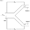
- FIG. 4 is a conceptual view conceptually illustrating an example of a flow field with a single inlet and a plurality of outlets.
- flow rates measured at the plurality of outlets may be acquired as flow rate values Q i outlet ( Q 1 outlet and Q 2 outlet in case of flow field of FIG. 4 ) of fluid at the respective outlets, and differences between pressure measured at the single inlet and pressures measured at the plurality of outlets may be acquired as pressure drop values ⁇ p i ( ⁇ p 1 and ⁇ p 2 in case of flow field of FIG. 4 ) of the fluid between the respective outlets and the single inlet.
- n may represent the number of outlets
- ⁇ p i may represent the pressure drops of the fluid between the single inlet and the respective outlets
- Q i outlet may represent the flow rates of the fluid at the respective outlets.
- the average energy dissipation rate ⁇ may be calculated by dividing the calculated total energy dissipation rate by the volume of the flow field.
- the apparent shear rate ⁇ app may be defined as a value obtained by dividing the flow rate Q i inlet at the single inlet by the cross-sectional area at the single inlet.
- the preparing of the flow numbers in the flow field may include acquiring the coefficient K p of energy dissipation rate in advance, and the coefficient K p of energy dissipation rate may be acquired for the corresponding flow field in advance.
- the coefficient K p of energy dissipation rate may be acquired through an experimental method.
- Newtonian fluid whose viscosity is known may be injected into the corresponding flow field system, i.e. the flow field with the specific shape, and a flow rate and pressure drop in a laminar flow region may be measured.
- the flow rate can be measured through a flow meter
- the pressure drop can be measured through a pressure gauge.
- the pressure drop may be calculated by comparing pressures at the start and end points of a specific section.
- the average energy dissipation rate may be calculated from the flow rate and pressure drop values in the laminar flow region and the volume of the flow field.
- the average energy dissipation rate ⁇ in the flow field which has the single inlet and the single outlet as illustrated in FIG. 2 may be expressed as a value obtained by dividing the product of the flow rate and the pressure drop in the laminar flow region by the volume of the flow field.
- two dimensionless numbers for quantifying flow characteristics based on the energy dissipation rate may be calculated based on the density, average velocity and viscosity of the Newtonian fluid, the characteristic length of the corresponding flow field, the apparent shear rate, and the average energy dissipation rate of the Newtonian fluid.
- Equation 3 ⁇ may represent the density of the fluid, U may represent the average velocity of the fluid, L may represent the characteristic length of the flow field system, and ⁇ may represent the viscosity of the fluid.
- the properties of the Newtonian fluid injected into the corresponding system may be used as the density ⁇ of the fluid and the viscosity ⁇ of the fluid in Equation 3.
- the average velocity U may be obtained by dividing the flow rate by the cross-sectional area, and the characteristic length of the system may be changed depending on the shape of the flow field.
- N p ⁇ ⁇ ⁇ ⁇ U ⁇ 2 ⁇ ⁇ app ⁇
- Equation 4 ⁇ may represent the average energy dissipation rate of the flow field, and ⁇ app may represent the apparent shear rate of the flow field.
- the average energy dissipation rate ⁇ of the flow field in Equation 4 may be calculated based on the volume of the flow field and the flow rate and pressure drop values of the Newtonian fluid, injected into the corresponding system, in the laminar flow region, and the apparent shear rate ⁇ app may be calculated based on the flow rate of the Newtonian fluid injected into the corresponding system.
- Equations 3 and 4 the values of the right sides are values which are already known or can be measured by related devices such as a velocity sensor. Thus, the Reynolds number Re and the power number N p may be calculated through the values.
- the coefficient K p of energy dissipation rate is calculated through the experimental method.
- the coefficient K p of energy dissipation rate may also be calculated through a numerical analysis method.
- the Newtonian fluid which has been used in the experimental method may be used to calculate a velocity field in the corresponding flow field.
- a local energy dissipation rate ⁇ 2 may be calculated by multiplying the viscosity of the Newtonian fluid by the square of a shear rate at a micro point of the flow field, and integrated for the entire flow field to calculate the total energy dissipation rate.
- the average energy dissipation rate may be calculated by dividing the calculated total energy dissipation rate by the volume of the flow field, and then used to calculate the coefficient K p of energy dissipation rate. After the average energy dissipation rate is calculated, the same method as the above-described experimental method may be used. That is, the Reynolds number and the power number may be calculated through the information including the calculated average energy dissipation rate, and the coefficient K p of energy dissipation rate may be calculated based on the relationship among the Reynolds number, the power number and the coefficient K p of energy dissipation rate.
- the preparing of the flow numbers in the flow field may include acquiring the coefficient K s of effective shear rate in advance, and the coefficient K s of effective shear rate may also be acquired for the corresponding flow field system in advance.
- the coefficient K s of effective shear rate may be acquired through an experimental method.
- non-Newtonian fluid xanthan gum solution or the like
- viscosity behavior viscosity-effective shear rate relationship
- the viscosity behavior (viscosity-effective shear rate relationship) of the non-Newtonian fluid may be expressed as illustrated in FIG. 1 , for example.
- the average energy dissipation rate ⁇ and the power number N p of the non-Newtonian fluid may be calculated from the flow rate and pressure drop values in the laminar flow region.
- the average energy dissipation rate ⁇ of the non-Newtonian fluid may be calculated based on the volume of the flow field and the flow rate and pressure drop values of the non-Newtonian fluid, injected into the corresponding system, in the laminar flow region.
- the power number N p may be calculated through Equation 4 based on the density ⁇ of the non-Newtonian fluid injected into the corresponding system, the average energy dissipation rate ⁇ of the non-Newtonian fluid, calculated based on the flow rate of the non-Newtonian fluid in the laminar flow region, the apparent shear rate ⁇ app and the average velocity U .
- N p ⁇ ⁇ ⁇ ⁇ U ⁇ 2 ⁇ ⁇ app ⁇
- a Reynolds number may be found, which corresponds to the power number N p of the Newtonian fluid having the same value as the power number N p calculated as described above.
- the Reynolds number at this time may be an effective Reynolds number Re eff of the complex fluid.
- the relationship between the power number N p of the Newtonian fluid and the Reynolds number Re corresponding to the power number N p may be defined by the coefficient K p of energy dissipation rate and Equation 5.
- the viscosity may be calculated through the effective Reynolds number Re eff , the density and average velocity of the non-Newtonian fluid and the characteristic length of the flow field.
- the viscosity calculated in this way may be the effective viscosity ⁇ eff of the complex fluid.
- Equation 3 ⁇ may represent the density of the fluid, U may represent the average velocity of the fluid, L may represent the characteristic length of the flow field system, and ⁇ may represent the viscosity of the fluid.
- the effective Reynolds number Re eff may be used as the Reynolds number Re
- the density of the non-Newtonian fluid injected into the corresponding system may be used as the density ⁇ of the fluid.
- the average velocity U may be obtained by dividing the flow rate by the cross-sectional area, and the characteristic length of the system may be changed depending on the shape of the flow field.
- an effective shear rate ⁇ eff may be found through the viscosity behavior (viscosity-effective shear rate relationship) of the complex fluid from the effective viscosity.
- Equation 2 K s ⁇ ⁇ app ⁇
- Equation 2 ⁇ may represent the average energy dissipation rate of the flow field, ⁇ eff may represent the effective shear rate of the flow field, ⁇ ( ⁇ eff ) may represent the viscosity of the fluid, ⁇ app represents the apparent shear rate of the flow field, K p may represent the coefficient of energy dissipation rate, and K s may represent the coefficient of effective shear rate.
- the coefficient K s of effective shear rate may also be calculated through the numerical analysis method.
- the non-Newtonian fluid whose viscosity behavior is known may be used to perform flow analysis in the flow field.
- a local energy dissipation rate ⁇ 2 may be calculated by multiplying the viscosity of the non-Newtonian fluid by the square of a shear rate at a micro point in the flow field, and then integrated for the entire flow field to calculate the total energy dissipation rate.
- the average energy dissipation rate may be calculated by dividing the total energy dissipation rate calculated as described above by the volume of the flow field, and the power number may also be calculated through Equation 4.
- N p ⁇ ⁇ ⁇ ⁇ U ⁇ 2 ⁇ ⁇ app ⁇
- Equation 4 ⁇ may represent the density of the fluid, U may represent the average velocity of the fluid, ⁇ may represent the average energy dissipation rate of the flow field, and ⁇ app may represent the apparent shear rate of the flow field.
- the density of the non-Newtonian fluid may be used as the density ⁇ of the fluid in Equation 4, and results derived through information such as the flow rate and the pressure drop, which can be acquired through flow analysis using a simulation, may be used as the average velocity U and the apparent shear rate ⁇ app of the fluid.
- a Reynolds number may be found, which corresponds to the power number N p of the Newtonian fluid having the same value as the calculated power number N p .
- the Reynolds number at this time may be an effective Reynolds number Re eff of the complex fluid.
- Equation 3 ⁇ may represent the density of the fluid, U may represent the average velocity of the fluid, L may represent the characteristic length of the flow field system, and ⁇ may represent the viscosity of the fluid.
- the density of the non-Newtonian fluid may be used as the density ⁇ of the fluid in Equation 3, and a result derived through information such as the flow rate and the pressure drop, which can be acquired through flow analysis using a simulation, may be used as the average velocity U of the fluid.
- the viscosity calculated in this way may be the effective viscosity ⁇ eff of the complex fluid.
- the effective shear rate ⁇ eff may be found from the effective viscosity through the viscosity behavior (viscosity-effective shear rate relationship) of the complex fluid.
- the coefficient K s of effective shear rate may be found through Equation 2.
- the coefficient K p of energy dissipation rate and the coefficient K s of effective shear rate may be a kind of flow numbers which do not have very much to do with the rheological properties of the fluid, and are related only to the shape of the system (flow field). Therefore, once the coefficient of energy dissipation rate and the coefficient of effective shear rate are calculated for a specific shape of flow field in advance, the flow characteristics of various complex fluids can be quantified afterwards.
- the fluid viscosity measurement system 100 can measure viscosity behaviors (viscosity, effective shear rate and relationship therebetween) of fluid or specifically non-Newtonian fluid by measuring only a flow rate and pressure drop of the actual fluid flowing in a specific shape of continuous flow field F having an inlet and outlet, when flow numbers are prepared, the flow numbers being obtained by quantifying the flow characteristics of unspecified fluids flowing in the continuous flow field F.
- the fluid viscosity measurement system 100 may used the above-described fluid viscosity measurement method.
- FIG. 5 is a conceptual view schematically illustrating a configuration of the fluid viscosity measurement system in accordance with another aspect of the embodiment of the present disclosure.
- the fluid viscosity measurement system 100 which measures viscosity in a specific shape of continuous flow field F having an inlet and outlet, may include a flow number storage unit 110 configured to store flow numbers in the flow field F; a flow rate measurement unit 120 configured to measure a flow rate of the fluid in the flow field F; a pressure measurement unit 130 configured to calculate a pressure drop in the flow field F; and a derivation unit 140 configured to calculate an average energy dissipation rate using the measured flow rate and pressure drop, and derive the viscosity of the fluid for an effective shear rate based on the average energy dissipation rate and the flow numbers in the flow field F.
- FIG. 5 illustrates an example in which the fluid viscosity measurement system 100 is applied to the continuous flow field F having the single inlet and the single outlet as illustrated in FIG. 2 .
- the shape of the continuous flow field to which the fluid viscosity measurement system 100 can be applied is not limited thereto. That is, the fluid viscosity measurement system 100 may also be applied to the continuous flow field having the plurality of inlets and the single outlet and the continuous flow field having the single inlet and the plurality of outlets as illustrated in FIGS. 3 and 4 .
- the fluid viscosity measurement system 100 may also be applied to a continuous flow field having a plurality of inlets and a plurality of outlets.
- the fluid viscosity measurement system 100 may also be applied to a continuous flow field having a complex cross-section as well as a continuous flow field having a simple cross-section such as a circular cross-section.
- the flow number storage unit 110 may store information on flow numbers obtained by quantifying the flow characteristics of unspecified fluids flowing in a specific shape of flow field with an inlet and outlet (for example, a circular cross-section pipe).
- the flow number storage unit 110 may be implemented as a nonvolatile memory, volatile memory, flash memory, hard disk drive (HDD) or solid state drive (SSD), which can store various data.
- the flow numbers of the flow field may include a coefficient K p of energy dissipation rate and/or a coefficient K s of effective shear rate for the corresponding flow field system, and be prepared through the preparing of the flow numbers in the flow viscosity measurement method. Since the preparing of the flow numbers in the flow viscosity measurement method has been described above, the detailed descriptions thereof are omitted herein.
- the flow rate measurement unit 120 may measure a flow rate of the fluid in the flow field F, which is information serving as the basis for calculating an average energy dissipation rate.
- the flow rate measurement unit 120 may include a flow meter disposed at one or more of the inlet and the outlet, and measure the flow rate of the fluid in the flow field F through the flow meter.
- the pressure measurement unit 130 may measure pressure at the inlet and/or outlet of the flow field F, in order to calculate a pressure drop in the flow field F, which is the information for calculating the average energy dissipation rate.
- the pressure drop of the flow field F may be calculated based on a difference between the pressures measured at the inlet and the outlet of the flow field F through the pressure measurement unit 130.
- the pressure measurement unit 130 may include at least a first pressure sensor 131 disposed at the inlet.
- a die installed in an extruder or injection machine which is used for processing polymer such as plastic is set to a continuous flow field as the target of viscosity measurement, pressure at an outlet of the die may correspond to the atmospheric pressure. Therefore, the pressure drop of the flow field F may be calculated by comparing the pressure at the inlet, measured by the first pressure sensor 131, to the pressure at the outlet, which is the atmospheric pressure information prepared in advance.
- the pressure measurement unit 130 may further include a second pressure sensor 132 disposed at the outlet.
- the pressure drop in the flow field F may be calculated by comparing the pressure at the inlet, measured by the first pressure sensor 131, to the pressure at the outlet, measured by the second pressure sensor 132.
- the derivation unit 140 may calculate an average energy dissipation rate by using and processing the flow rate measured by the flow rate measurement unit 120 and the pressure drop information which may be calculated through the pressure measurement unit 130, and derive the viscosity of the fluid for the effective shear rate by using and processing the information on the flow numbers in the flow field F, stored in the flow number storage unit 110.
- the derivation unit 140 may be a program module or software including a computing algorithm for generating new data by using and processing the various pieces of information stored in the flow number storage unit 110 and the various pieces of information measured through the flow rate measurement unit 120 and/or the pressure measurement.
- the derivation unit 140 may derive the viscosity of the fluid for the effective shear rate through the deriving of the viscosity of the fluid for the effective shear rate in the fluid viscosity measurement method. That is, since the deriving of the viscosity of the fluid for the effective shear rate can be performed through Equations 1 and 2 and have been described above, the detailed descriptions thereof are omitted herein.
- FIG. 6 illustrates that results obtained by calculating the viscosities of Carbopol 981 solution flows in circular pipes expanded/contracted at various ratios for the shear rate through simulations coincide with results obtained by calculating viscosities using only the flow rate and pressure drop information based on the coefficient of energy dissipation rate and the coefficient of effective shear rate, which are calculated in advance.
- the graph on the right side illustrates the actual viscosity behavior of Carbopol 981 0.2wt% solution and viscosities predicted through the method in accordance with the embodiment of the present disclosure.
- the graph shows that, when the coefficients of energy dissipation rate for the respective extraction/contraction ratios are calculated to predict the viscosities even though the extraction/contraction ratios are different, the actual viscosity behaviors can be accurately predicted.
- the Carbopol 981 solution is a representative example of non-Newtonian fluid which exhibits yield stress and shear-thinning at the same time.
- FIG. 7A is a schematic view illustrating a specific shape of die
- FIG. 7B is a graph illustrating that results obtained by calculating the viscosities of flows of two kinds of non-Newtonian fluid models in the die illustrated in FIG. 7A for the shear rate through simulations coincide with results obtained by calculating viscosities using only the flow rate and pressure drop information based on the coefficient of energy dissipation rate and the coefficient of effective shear rate, which are calculated in advance.
- FIG. 7A illustrates a specific shape of die having a single inlet and a single outlet.
- results obtained by calculating the viscosities of the two kinds of non-Newtonian fluid models (power-law and Carreau) for the shear rate, through a simulation using a program based on a finite element method (FEM), are indicated by solid lines, and results obtained by calculating viscosities for the shear rate using only the flow rate and pressure drop information based on the coefficient of energy dissipation rate and the coefficient of effective shear rate, which are calculated for the corresponding die in advance, are indicated by points.
- FIG. 7B shows that the results obtained by calculating the viscosities for the shear rate, which are derived through the simulation, coincide with the results obtained by calculating the viscosities for the shear rate, which are derived in accordance with the embodiment of the present disclosure.
- the method for predicting a flow rate or pressure drop of non-Newtonian fluid in accordance with an aspect of another embodiment of the present disclosure relates to a method capable of predicting a flow rate or pressure drop of actual non-Newtonian fluid which flows in a specific shape of flow field having an inlet and outlet like a pipe, when flow numbers obtained by quantifying flow characteristics of unspecified fluids flowing in the flow field and viscosity behaviors (viscosity, effective shear rate and relationship therebetween) of the non-Newtonian fluid are prepared in advance.
- the method for predicting a flow rate or pressure drop of non-Newtonian fluid may include preparing flow numbers in a flow field; preparing viscosity behavior information of the non-Newtonian fluid; and deriving any one piece of information between the flow rate and the pressure drop of the non-Newtonian fluid in the flow field from the other piece of information, based on the flow numbers in the flow field and the viscosity behavior information of the non-Newtonian fluid.
- the deriving of the any one piece of information between the flow rate and the pressure drop of the non-Newtonian fluid in the flow field from the other piece of information will be referred to as 'the deriving of the any one piece of information'.
- a pressure drop corresponding to the flow rate may be predicted.
- a flow rate corresponding to the pressure drop may be predicted.
- the flow characteristics of unspecified complex fluids flowing in a specific shape of flow field may be flow numbers quantified regardless of the types of fluids, i.e. dimensionless numbers.
- the flow numbers in such a flow field may include a coefficient K p of energy dissipation rate and/or a coefficient K s of effective shear rate.
- the flow numbers in such a flow field may be calculated through the relationship between a dimensionless number N p and a Reynolds number Re, which can indicate energy dissipation for a specific shape of flow field. Since the preparing of the flow numbers in the flow field is performed in substantially the same manner as the preparing of the flow numbers in the flow field in the above-described fluid viscosity measurement method, the detailed descriptions thereof are omitted herein.
- the preparing of the viscosity behavior information of the non-Newtonian fluid may include preparing the viscosity behavior curve of FIG. 1 , which shows the viscosity-effective shear rate relationship. Such a viscosity behavior curve may be obtained through a viscosity measurement device.
- Equation 6 P / V ⁇ ⁇ U ⁇ 2 ⁇ ⁇ app ⁇
- N p may represent a power number
- P may represent the product of the flow rate and the pressure drop as total stress power
- ⁇ app may represent an apparent shear rate of the flow field
- ⁇ eff may represent an effective shear rate of the flow field
- Re may represent the Reynolds number
- K p may represent the coefficient of energy dissipation rate
- K s may represent the coefficient of effective shear rate.
- the deriving of the any one piece of information may include calculating the effective shear rate using the relationship between the apparent shear rate ⁇ app and the coefficient K s of effective shear rate derived through the flow characteristics of the flow field.
- the apparent shear rate ⁇ app may indicate a function of the flow rate of the non-Newtonian fluid flowing in the flow field.
- the relationship between the apparent shear rate ⁇ app and the coefficient K s of effective shear rate may be defined as Equation 8, and the effective shear rate ⁇ eff may be derived through Equation 8.
- the effective shear rate ⁇ eff may be derived as a function of the flow rate of the non-Newtonian fluid like the apparent shear rate ⁇ app .
- an effective viscosity may be calculated through the derived effective shear rate and the prepared viscosity behaviors (viscosity-effective shear rate relationship and viscosity behavior curve) of the non-Newtonian fluid.
- the effective viscosity may be represented by ⁇ eff .
- the effective viscosity ⁇ eff may also indicate a function of the flow rate of the non-Newtonian fluid like the effective shear rate ⁇ eff .
- an effective Reynolds number may be calculated based on the relationship between the average velocity, density and viscosity of the fluid and the characteristic length of the flow field, and the derived effective viscosity.
- ⁇ may represent the density of the fluid
- U may represent the average velocity of the fluid
- L may represent the characteristic length of the flow field system
- ⁇ may represent the viscosity of the fluid.
- the average velocity U of the fluid may be obtained by dividing the flow rate of the fluid by the cross-sectional area, and the characteristic length of the flow field system may be changed depending on the shape of the flow field.
- the density ⁇ of the fluid may be decided according to the type of the non-Newtonian fluid
- the characteristic length L of the flow field may be decided according to the shape of the flow field
- the effective viscosity ⁇ eff may indicate a function of the flow rate of the fluid as the average velocity U of the fluid and the viscosity ⁇ of the fluid. Therefore, the effective Reynolds number Re eff derived as the Reynolds number Re may also indicate a function of the flow rate of the fluid.
- the prepared coefficient K s of effective shear rate in the flow field and the previously derived effective Reynolds number Re eff may be used to calculate a power number.
- the power number may be derived through Equation 7.
- the power number N p derived through the Reynolds number Re may also indicate a function of the flow rate of the fluid.
- Equation 6 may be used.
- the density ⁇ of the fluid may be decided according to the type of the non-Newtonian fluid
- the volume of the fluid may be decided according to the shape of the flow field
- the average velocity U , the apparent shear rate ⁇ app and the power number N p of the fluid may be functions of the flow rate of the fluid as described above. Therefore, the total power P for stress, derived through Equation 6, may also indicate a function of the flow rate of the fluid.
- the total power P for stress may be expressed as the product of the pressure drop and the flow rate of the fluid as expressed by Equation 10.
- P ⁇ ⁇ p ⁇ Q
- Equation 10 P may represent the total power P for stress, ⁇ p may represent the pressure drop of the fluid, and Q may represent the flow rate of the fluid.
- the corresponding equation may be arranged as an equation which includes a constant number decided by the shape of the flow field, the flow characteristics in the flow field, and the viscosity behavior of the non-Newtonian fluid, and variable numbers such as the pressure drop and flow rate of the fluid. That is, the relationship between pressure drop and flow rate of specific non-Newtonian fluid in the corresponding flow field can be derived.
- Equation 11 the relationship between pressure drop and flow rate of non-Newtonian fluid flowing in a general flow field system having a characteristic length L and the entire volume V may be derived as expressed by Equation 11 below.
- Equation 11 K p V U ⁇ ⁇ app ⁇ QL ⁇ eff
- Equation 11 ⁇ p may represent the pressure drop of the fluid, Q may represent the flow rate of the fluid, K p may represent the coefficient of energy dissipation rate, V may represent the volume of the flow field, L may represent the characteristic length of the flow field, U may represent the average velocity of the fluid, ⁇ app may represent the apparent shear rate, and ⁇ eff may represent the effective viscosity.
- the pressure drop of the non-Newtonian fluid, corresponding to the flow rate may be derived.
- Equation 11 is derived based on the function of the flow rate of the non-Newtonian fluid, and the variable numbers on the right side include a plurality of variable numbers related to the function of the flow rate of the non-Newtonian fluid. Therefore, a computing device, software or numerical analysis tool including an algorithm capable of finding a flow rate solution related to the variable numbers may be used. In addition to such a tool, another method may be used to derive the flow rate of the non-Newtonian fluid. The method may include arranging random flow rates of the non-Newtonian fluid and pressure drops corresponding to the flow rates as table data through Equation 11, and finding flow rate information corresponding to specific pressure drop information of the non-Newtonian fluid based on the arranged data.
- Equation 11 the relationship between pressure drop and flow rate in a flow field formed in a simple circular pipe having a radius R and the entire volume V may be derived as Equation 12.
- ⁇ ⁇ p 2 K p ⁇ eff V / ⁇ 2 R 6 Q
- ⁇ eff ⁇ ⁇ eff ⁇
- ⁇ eff ⁇ K s ⁇ ⁇ app ⁇
- FIG. 8 is a conceptual view illustrating a configuration of a system for predicting a flow rate or pressure drop of non-Newtonian fluid in accordance with another aspect of the another embodiment of the present disclosure.
- the system for predicting a flow rate or pressure drop of non-Newtonian fluid in accordance with the another aspect of the another embodiment of the present disclosure relates to a system capable of predicting a flow rate or pressure drop of non-Newtonian fluid which flows in a specific shape of flow field having an inlet and outlet like a pipe, when flow numbers obtained by quantifying flow characteristics of unspecified fluids flowing in the flow field and viscosity behaviors (viscosity, effective shear rate and relationship therebetween) of the non-Newtonian fluid are prepared in advance.
- Such a prediction system may use the above-described method for predicting a flow rate or pressure drop of non-Newtonian fluid in accordance with the aspect of another embodiment of the present disclosure. Since the roles of components included in the prediction system may correspond to the technical contents of the plurality of steps included in the method for predicting a flow rate or pressure drop of non-Newtonian fluid in accordance with the aspect of the another embodiment of the present disclosure, the detailed descriptions thereof are omitted herein.
- the prediction system 200 may include a flow number storage unit 210 configured to store flow numbers in a flow field; a viscosity behavior information storage unit 220 configured to store viscosity behavior information of non-Newtonian fluid; and a derivation unit 230 configured to derive any one piece of information between a flow rate and a pressure drop of the non-Newtonian fluid in the flow field from the other piece of information, based on the flow numbers in the flow field and the viscosity behavior information.
- the flow number storage unit 210 and the viscosity behavior information storage unit 220 may be implemented as a nonvolatile memory, volatile memory, flash memory, hard disk drive (HDD) or solid state drive (SSD), which can store various data.
- the derivation unit 230 may be a program module or software including a computing algorithm that generates new data by using and processing the various data stored in the flow number storage unit 210 and the viscosity behavior information storage unit 220.
- the flow number storage unit 210 may store a coefficient K p of energy dissipation rate and a coefficient K s of effective shear rate, which are acquired for the corresponding flow field system in advance. Since the method for calculating the coefficient K p of energy dissipation rate and the coefficient K s of effective shear rate has been described above, the detailed descriptions thereof are omitted herein.
- the viscosity behavior information storage unit 220 may store the viscosity behavior curve of FIG. 1 , which shows the viscosity-effective shear rate relationship of the non-Newtonian fluid as the target of prediction, and viscosity-effective shear rate coordinate information of the viscosity behavior curve.
- the derivation unit 230 may calculate a pressure drop corresponding to the flow rate of the non-Newtonian fluid or a flow rate corresponding to the pressure drop of the non-Newtonian fluid, using one or more of Equations 6, 7 and 8 described above.
- the derivation unit 230 may derive pressure drop information corresponding to the flow rate information of the non-Newtonian fluid or flow rate information corresponding to the pressure drop information of the non-Newtonian fluid, using a functional relation equation including a pressure drop variable and variables which can be derived based on the flow rate of the non-Newtonian fluid in the flow field, or table data indicating the relationship between flow rate information and pressure drop information of the non-Newtonian fluid in the flow field.
- the derivation unit 230 may include: an effective shear rate calculation unit 231 configured to calculate the effective shear rate using the relationship between the apparent shear rate and the coefficient K s of effective shear rate; an effective viscosity calculation unit 232 configured to calculate an effective viscosity using the effective shear rate and the viscosity behavior; an effective Reynolds number calculation unit 233 configured to calculate an effective Reynolds number using the effective viscosity and the relationship between the average velocity, density and viscosity of the fluid and the characteristic length of the flow field; a power number calculation unit 234 configured to calculate a power number using the coefficient K s of effective shear rate and the effective Reynolds number; and a total power calculation unit 235 configured to calculate total stress power using the average velocity and density of the fluid, the apparent shear rate, the volume of the fluid in the flow field, and the power number.
- the total power calculation unit 235 may calculate the relationship between flow rate and pressure drop of the non-Newtonian fluid in the flow field, based on the calculated total stress power.
- the derivation unit 230 may further include a flow rate information utilization unit 236 configured to calculate one or more of the apparent shear rate and the average velocity of the fluid, through the flow rate information of the non-Newtonian fluid in the flow field.
- a flow rate information utilization unit 236 configured to calculate one or more of the apparent shear rate and the average velocity of the fluid, through the flow rate information of the non-Newtonian fluid in the flow field.
- One or more of the effective shear rate calculation unit 231, the effective Reynolds number calculation unit 233 and the total power calculation unit 235 may use the information derived by the flow rate information utilization unit 236.
- the coefficient K p of energy dissipation rate and the coefficient K s of effective shear rate may be a kind of flow numbers which do not have very much to do with the rheological properties of the fluid, and are related only to the shape of the system (flow field). Therefore, once the coefficient of energy dissipation rate and the coefficient of effective shear rate are calculated for a specific shape of flow field in advance, the flow characteristics of various complex fluids or specifically non-Newtonian fluid, such as the relationship between pressure drop and flow rate, can be quantified afterwards.
- the quantified information between pressure drop and flow rate which is referred to as the die characteristics of an extrusion die used for processing polymer, may be used to easily derive the optimal process.
- FIG. 9 illustrates that results obtained by simulating pressure drops corresponding to random flow rates for flows in expanded/contracted circular pipes through flow analysis almost coincide with results obtained by predicting pressure drops corresponding to random flow rates using the method and/or system for predicting a flow rate or pressure drop of non-Newtonian fluid in accordance with the aspect of the another embodiment of the present disclosure.
- the non-Newtonian fluid model used herein may include a total of three kinds of models, that is, a power-law model, a Carreau model and a modified H-B model.
- the flows in the expanded/contracted circular pipes in FIG. 9 may have the following flow number information.
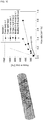
- FIG. 10 illustrates that results obtained by simulating pressure drops corresponding to random flow rates for flows in a "Kenics static mixer" through flow analysis almost coincide with the results (certain result) obtained by predicting pressure drops corresponding to random flow rates using the method and/or system for predicting a flow rate or pressure drop of non-Newtonian fluid in accordance with the aspect of the another embodiment of the present disclosure.
- the non-Newtonian fluid model used herein may include a total of three kinds of models, that is, the power-law model, the Carreau model and the modified H-B model.
- the flows in the "Kenics static mixer" in FIG. 10 may have the following flow number information.
- FIG. 11 illustrates that results obtained by simulating pressure drops corresponding to random flow rates for flows in a "porous medium with a body-centered cubic (BCC) structure" through flow analysis almost coincide with the results obtained by predicting pressure drops corresponding to random flow rates using the method and/or system for predicting a flow rate or pressure drop of non-Newtonian fluid in accordance with the aspect of the another embodiment of the present disclosure.
- BCC body-centered cubic
- the non-Newtonian fluid model used herein is the power-law model.
- the flows corresponding to respective volume fractions vf within the "porous medium with a BCC structure" in FIG. 11 may have the following flow number information.
Landscapes
- Physics & Mathematics (AREA)
- General Physics & Mathematics (AREA)
- Health & Medical Sciences (AREA)
- Life Sciences & Earth Sciences (AREA)
- Chemical & Material Sciences (AREA)
- Analytical Chemistry (AREA)
- Biochemistry (AREA)
- General Health & Medical Sciences (AREA)
- Immunology (AREA)
- Pathology (AREA)
- Fluid Mechanics (AREA)
- Measuring Volume Flow (AREA)
Abstract
Description
- The present disclosure relates to a viscosity measurement method and system for a continuous flow field, and a method and system for predicting a flow rate or pressure drop of non-Newtonian fluid in a continuous flow field.
- Rheologically complex fluid such as polymer melt and solution, particle suspension, slurry and droplet system exhibits a complex viscosity change such as shear-thinning and yield stress through a hydrodynamic interaction with a microstructure, and is applied to various processes such as a chemical process, polymer processing, electronic material (display and secondary battery) processing, food processing, cosmetics processing, paint processing, water treatment and oil drilling.
- An existing method for measuring the viscosity of such complex fluid basically takes a sample of the fluid and uses one of the following methods. A first method (i) may include putting the fluid between flat plates, applying a shearing force to one of the plates to measure a shear rate, and measuring the viscosity of the fluid through the relationship between the shearing force and the shear rate. A second method (ii) may include passing the fluid to a thin micro-tube with a simple circular or rectangular cross-section, and measuring the viscosity of the fluid using the relationship between pressure difference and flow rate.
- However, since the above two methods are induced from the principle of conversation of momentum (force balance), the methods can be applied only to a very simple shape (circular plate, circular cross-section tube or rectangular slit).
- In addition, there is the Metzner-Otto method as a flow quantification method based on an energy dissipation rate, which is applied as a scaling concept and empirical access only in flows in existing limited mixers. The Metzner-Otto method has been based on the supposition that there is an average shear rate representing the entire flow fields in a mixing system, has defined such a correlation that the average shear rate is proportional to the velocity of an impeller, and has defined an effective shear rate and effective viscosity of non-Newtonian fluid flowing in a mixer based on the fact that Newtonian fluid and non-Newtonian fluid have the same energy dissipation rate. The present disclosure has been developed to apply a quantification method based on an energy dissipation rate, which is similar to the Metzner-Otto method, to all continuous flow fields with an inlet and outlet.
- Examples of the related art may include
US Patent No. 6,412,337 . According to this related art, the Metzner-Otto concept has been expanded to measure viscosity in a static mixer. The related art is also based on the fact that Newtonian fluid and non-Newtonian fluid have the same energy dissipation rate. However, the related art is based on the supposition that a viscosity model of fluid is power-law fluid, and discloses "connecting two static mixers" to measure a pressure drop and a flow rate, in order to find two kinds of coefficients of the power-law fluid, i.e. a consistency index and a power-law index. However, the present disclosure can measure viscosity through only one on-site operation of measuring a pressure drop and a flow rate in a flow field of arbitrary geometry, without deciding a viscosity model in advance. Therefore, the present invention is different from the above-described related art, and may have a much wider application range. When the application range is wide, it may indicate that the present disclosure can treat various viscosity models of fluid, and be applied to any types of general flow fields as well as a static mixer. - In a continuous flow field, the relationships between flow rate and pressure drop for the properties of non-Newtonian fluids are very different from one another. In the related art, the relationships between flow rate and pressure drop for the respective fluids had to be separately calculated through flow analysis or experiments, which was very inconvenient.
- For example, the relationships between flow rate and pressure drop, which is referred to as die characteristics of an extrusion die used for polymer processing, serve as very important information for deciding a process condition and the like. Since the relationships between flow rate and pressure drop are different depending on the types and temperatures of polymers used for the process, the relationships between flow rate and pressure drop had to be calculated through separate experiments and analyses for respective fluids used in the process, which was very inconvenient.
- Various embodiments are directed to a method which can easily measure viscosity behaviors of fluid by calculating flow numbers in a continuous flow field of arbitrary geometry, and measuring only a flow rate and pressure drop using the flow number.
- Also, various embodiments are directed to a method which can measure the viscosity of fluid through an on-site treatment in an actual system during an in-situ process in a continuous flow field of arbitrary geometry with an inlet and outlet.
- Also, various embodiments are directed to a method and system which can easily predict a pressure drop or flow rate of non-Newtonian fluid, once only the flow characteristics of a continuous flow field of arbitrary geometry and the viscosity behaviors of the non-Newtonian fluid are prepared.
- In an embodiment, there is provided a method for measuring viscosity in a specific shape of continuous flow field having an inlet and outlet. The method may include: preparing flow numbers in the flow field; measuring a flow rate and pressure drop of fluid in the flow field; and calculating an average energy dissipation rate using the flow rate and the pressure drop, and deriving the viscosity of the fluid for an effective shear rate based on the average energy dissipation rate and the flow number in the flow field.
- The deriving of the viscosity of the fluid may include deriving the viscosity of the fluid for the effective shear
rate using Equations 

ε represents the average energy dissipation rate of the flow field as a function of the flow rate, the pressure drop and the volume of the flow field, γ̇eff represents an effective shear rate of the flow field, µ(γ̇eff ) represents the viscosity of the fluid at the effective shear rate, γ̇app represents an apparent shear rate of the flow field, Kp represents a coefficient of energy dissipation rate, and Ks represents a coefficient of effective shear rate. - The continuous flow field may have a plurality of inlets and a single outlet, and the deriving of the viscosity of the fluid may include calculating a total energy dissipation rate using Equation A below, and calculating the average energy dissipation rate based on the total energy dissipation rate and the volume of the flow field:


- The continuous flow field has a single inlet and a plurality of outlets, wherein the deriving of the viscosity of the fluid may include calculating a total energy dissipation rate using Equation B below, and calculating the average energy dissipation rate based on the total energy dissipation rate and the volume of the flow field:


- The flow number in the flow field may include a coefficient of energy dissipation rate. The preparing of the flow number in the flow field may include acquiring the coefficient of energy dissipation rate in advance. The acquiring of the coefficient of energy dissipation rate in advance may include: injecting Newtonian fluid, whose viscosity is known, into the flow field; measuring a flow rate and pressure drop of the Newtonian fluid in the flow field; calculating an average energy dissipation rate of the Newtonian fluid, using the flow rate and the pressure drop of the Newtonian fluid; calculating a Reynolds number and a power number using a density, average velocity and viscosity of the Newtonian fluid, a characteristic length of the flow field, an apparent shear rate of the Newtonian fluid, and the average energy dissipation rate of the Newtonian fluid; and calculating the coefficient of energy dissipation rate using the relationship among the Reynolds number, the power number and the coefficient of energy dissipation rate.
- The flow number in the flow field may include a coefficient of energy dissipation rate. The preparing of the flow number in the flow field may include acquiring the coefficient of energy dissipation rate in advance. The acquiring of the coefficient of energy dissipation rate in advance may include: calculating a velocity field of the flow field using Newtonian fluid; calculating a local energy dissipation rate by multiplying a viscosity of the Newtonian fluid by the square of a shear rate at a micro point of the flow field; calculating a total energy dissipation rate by integrating the local energy dissipation rate for the entire flow field; calculating an average energy dissipation rate of the Newtonian fluid by dividing the total energy dissipation rate by the volume of the flow field; calculating a Reynolds number and a power number using a density, average velocity and viscosity of the Newtonian fluid, a characteristic length of the flow field, an apparent shear rate of the Newtonian fluid, and the average energy dissipation rate of the Newtonian fluid; and calculating the coefficient of energy dissipation rate using the relationship among the Reynolds number, the power number and the coefficient of energy dissipation rate.
- The flow number in the flow field may include a coefficient of effective shear rate. The preparing of the flow number in the flow field may include acquiring the coefficient of effective shear rate in advance. The acquiring of the coefficient of effective shear rate in advance may include: injecting non-Newtonian fluid, whose viscosity behavior is known, into the flow field; measuring a flow rate and pressure drop of the non-Newtonian fluid in the flow field; calculating an average energy dissipation rate and power number of the non-Newtonian fluid, using the flow rate and the pressure drop of the non-Newtonian fluid; finding a Reynolds number of Newtonian fluid, corresponding to a power number of the Newtonian fluid, which is equal to the power number of the non-Newtonian fluid, and considering the Reynolds number of the Newtonian fluid as an effective Reynolds number; calculating a viscosity of the non-Newtonian fluid using the effective Reynolds number, a density and average velocity of the non-Newtonian fluid, and a characteristic length of the flow field, and considering the viscosity as an effective viscosity; calculating an effective shear rate of the flow field using the effective viscosity and the viscosity behavior; and calculating the coefficient of effective shear rate using the relationship between the effective shear rate and the apparent shear rate.
- The flow number in the flow field may include a coefficient of effective shear rate. The preparing of the flow number in the flow field may include acquiring the coefficient of effective shear rate in advance. The acquiring of the coefficient of effective shear rate in advance may include: performing flow analysis using non-Newtonian fluid whose viscosity behavior is known; calculating a local energy dissipation rate by multiplying a viscosity of the non-Newtonian fluid by the square of a shear rate at a micro point of the flow filed; calculating a total energy dissipation rate by integrating the local energy dissipation rate for the entire flow field; calculating an average energy dissipation rate of the non-Newtonian fluid by dividing the total energy dissipation rate by the volume of the flow field; calculating a power number using the density, average velocity and apparent shear rate of the non-Newtonian fluid, and the average energy dissipation rate; finding a Reynolds number of Newtonian fluid, corresponding to a power number of the Newtonian fluid, which is equal to the power number of the non-Newtonian fluid, and considering the corresponding Reynolds number of the Newtonian fluid as an effective Reynolds number; calculating a viscosity of the non-Newtonian fluid using the effective Reynolds number, a density and average velocity of the non-Newtonian fluid, and a characteristic length of the flow field, and considering the viscosity as an effective viscosity; calculating an effective shear rate of the flow field using the effective viscosity and the viscosity behavior; and calculating the coefficient of effective shear rate using the relationship between the effective shear rate and the apparent shear rate.
- In another embodiment, there is provided a system for measuring viscosity in a specific shape of continuous flow field having an inlet and outlet. The system may include: a flow number storage unit configured to store a flow number in the flow field; a flow rate measurement unit configured to measure a flow rate of fluid in the flow field; a pressure measurement unit configured to calculate a pressure drop in the flow field; and a derivation unit configured to calculate an average energy dissipation rate using the measured flow rate and pressure drop, and derive the viscosity of the fluid for an effective shear rate based on the average energy dissipation rate and the flow number in the flow field.
- The deviation unit derives the viscosity of the fluid for the effective shear
rate using Equations 

ε represents the average energy dissipation rate of the flow field as a function of the flow rate, the pressure drop and the volume of the flow field, γ̇eff represents the effective shear rate of the flow field, µ(γ̇eff ) represents the effective viscosity of the fluid, γ̇app represents an apparent shear rate of the flow field, Kp represents a coefficient of energy dissipation rate, and Ks represents a coefficient of effective shear rate. - The continuous flow field may have a plurality of inlets and a single outlet. The derivation unit may calculate a total energy dissipation rate using Equation A below, and calculate the average energy dissipation rate based on the total energy dissipation rate and the volume of the flow field:


- The continuous flow field may have a single inlet and a plurality of outlets. The derivation unit may calculate a total energy dissipation rate using Equation B below, and calculate the average energy dissipation rate based on the total energy dissipation rate and the volume of the flow field:


- In another embodiment, there is provided a method for predicting a flow rate or pressure drop of non-Newtonian fluid flowing in a specific shape of continuous flow field having an inlet and outlet. The method may include: preparing a flow number in the flow field; preparing viscosity behavior information of the non-Newtonian fluid; and deriving any one piece of information between the flow rate and the pressure drop of the non-Newtonian fluid in the flow field from the other piece of information, based on the flow number in the flow field and the viscosity behavior information.
- The deriving of the any one piece of information may include using one or more of
Equation 6, Equation 7 andEquation 8 below:


- The flow number in the flow field may include the coefficient of energy dissipation rate and the coefficient of effective shear rate. The deriving of the any one piece of information may include: calculating the effective shear rate of the flow field using the relationship between the apparent shear rate of the flow field and the coefficient of effective shear rate; calculating an effective viscosity using the effective shear rate of the flow field and the viscosity behavior; calculating an effective Reynolds number using the effective viscosity and the relationship between an average velocity, density and viscosity of the fluid and a characteristic length of the flow field; calculating the power number using the coefficient of effective shear rate and the effective Reynolds number; and calculating the total stress power using the average velocity, density and apparent shear rate of the fluid, the volume of the fluid in the fluid field, and the power number. The relationship between the flow rate and the pressure drop of the non-Newtonian fluid in the flow field may be calculated through the calculating of the total stress power.
- In the deriving of the any one piece of information, the any one piece of information may be the flow rate information of the non-Newtonian fluid in the flow field. The deriving of the any one piece of information may further include calculating one or more of the apparent shear rate and the average velocity of the fluid through the flow rate information of the non-Newtonian fluid in the flow field.
- In another embodiment, there is provided a system for predicting a flow rate or pressure drop of non-Newtonian fluid flowing in a specific shape of continuous flow field having an inlet and outlet. The system may include: a flow number storage unit configured to store a flow number in the flow field; a viscosity behavior information storage unit configured to store viscosity behavior information of the non-Newtonian fluid; and a derivation unit configured to derive any one piece of information between the flow rate and the pressure drop of the non-Newtonian fluid in the flow field from the other piece of information, based on the flow number in the flow field and the viscosity behavior information.
- The derivation unit may use one or more of
Equation 6, Equation 7 andEquation 8 below:


- The flow number in the flow field may include the coefficient of energy dissipation rate and the coefficient of effective shear rate. The derivation unit may include: an effective shear rate calculation unit configured to calculate the effective shear rate using the relationship between the apparent shear rate and the coefficient of effective shear rate; an effective viscosity calculation unit configured to calculate an effective viscosity using the effective shear rate and the viscosity behavior; an effective Reynolds number calculation unit configured to calculate the effective Reynolds number using the effective viscosity and the relationship between an average velocity, density and viscosity of the fluid and a characteristic length of the flow field; a power number calculation unit configured to calculate the power number using the coefficient of effective shear rate and the effective Reynolds number; and a total power calculation unit configured to calculate the total stress power using the average velocity, density and apparent shear rate of the fluid, the volume of the fluid in the fluid field, and the power number. The total power calculation unit may calculate the relationship between flow rate and pressure drop of non-Newtonian fluid in the flow field based on the calculated total stress power.
- The any one piece of information may be the flow rate information of the non-Newtonian fluid in the flow field. The derivation unit further may include a flow rate information utilization unit configured to calculate one or more of the apparent shear rate and the average velocity of the fluid through the flow rate information of non-Newtonian fluid in the flow field.
- In accordance with an embodiment of the present disclosure, it is possible to provide a method and/or system which can easily measure viscosity behaviors of fluid by calculating a flow number in a continuous flow field of arbitrary geometry and measuring only a flow rate and pressure drop using the flow number.
- Furthermore, it is possible to provide a method and/or system which can measure the viscosity of fluid through an on-site treatment in an actual system during an in-situ process in a continuous flow field of arbitrary geometry with an inlet and outlet.
- In accordance with another embodiment of the present disclosure, it is possible to provide a method and/or system which can easily predict a pressure drop or flow rate in a continuous flow field of arbitrary geometry, once only the flow characteristics of the corresponding flow field and the viscosity behaviors of the non-Newtonian fluid are prepared.
-
-
FIG. 1 is a graph illustrating the relationship between shear rate and viscosity of rheologically complex fluid. -
FIG. 2 is a conceptual view conceptually illustrating an example of a flow field with a single inlet and a single outlet. -
FIG. 3 is a conceptual view conceptually illustrating an example of a flow field with a plurality of inlets and a single outlet. -
FIG. 4 is a conceptual view conceptually illustrating an example of a flow field with a single inlet and a plurality of outlets. -
FIG. 5 is a conceptual view schematically illustrating a configuration of a fluid viscosity measurement system in accordance with another aspect of an embodiment of the present disclosure. -
FIG. 6 illustrates that results obtained by calculating the viscosities of Carbopol 981 solution flows in circular pipes expanded/contracted at various ratios for the shear rate through simulations coincide with results obtained by calculating viscosities using only flow rate and pressure drop information based on a coefficient of energy dissipation rate and a coefficient of effective shear rate, which are calculated in advance. -
FIG. 7A is a schematic view illustrating a specific shape of die. -
FIG. 7B is a graph illustrating that results obtained by calculating the viscosities of flows of two kinds of non-Newtonian fluid models in the die illustrated inFIG. 7A for the shear rate through simulations coincide with results obtained by calculating viscosities using only flow rate and pressure drop information based on a coefficient of energy dissipation rate and a coefficient of effective shear rate, which are calculated in advance. -
FIG. 8 is a conceptual view illustrating a configuration of a system for predicting a flow rate or pressure drop of non-Newtonian fluid in accordance with another aspect of another embodiment of the present disclosure. -
FIG. 9 illustrates that results obtained by simulating pressure drops corresponding to random flow rates for flows in expanded/contracted circular pipes through flow analysis almost coincide with results obtained by predicting pressure drops corresponding to random flow rates using a method and/or system for predicting a flow rate or pressure drop of non-Newtonian fluid in accordance with an aspect of the another embodiment of the present disclosure. -
FIG. 10 illustrates that results obtained by simulating pressure drops corresponding to random flow rates for flows in a "Kenics static mixer" through flow analysis almost coincide with the results obtained by predicting pressure drops corresponding to random flow rates using the method and/or system for predicting a flow rate or pressure drop of non-Newtonian fluid in accordance with the aspect of the another embodiment of the present disclosure. -
FIG. 11 illustrates that results obtained by simulating pressure drops corresponding to random flow rates for flows in a "porous medium with a body-centered cubic (BCC) structure" through flow analysis almost coincide with the results obtained by predicting pressure drops corresponding to random flow rates using the method and/or system for predicting a flow rate or pressure drop of non-Newtonian fluid in accordance with the aspect of the another embodiment of the present disclosure. - Hereafter, specific embodiments will be described in detail with reference to the accompanying drawings. Moreover, detailed descriptions of well-known functions or configurations will be ruled out in order not to unnecessarily obscure subject matters of the present invention.
- The terms of a singular form may include plural forms unless referred to the contrary. Furthermore, when a specific part "includes" or "comprises" a specific component, it indicates that the specific part does not exclude other components other than the specific component, but may further include the other components, unless referred to the contrary.
- Hereafter, a fluid viscosity measurement method in accordance with an aspect of an embodiment of the present disclosure will be described in detail. The fluid viscosity measurement method in accordance with the aspect of the present embodiment relates to a method capable of measuring viscosity behaviors (viscosity, effective shear rate and relationship therebetween) of fluid or specifically non-Newtonian fluid by measuring only a flow rate and pressure drop of the actual fluid flowing in a specific shape of continuous flow field with an inlet and outlet like a pipe, when flow numbers are prepared, the flow numbers being obtained by quantifying flow characteristics of unspecified fluids flowing in the continuous flow field.
- Such a fluid viscosity measurement method may include preparing flow numbers in a flow field; measuring a flow rate and pressure drop of fluid in the flow field; and calculating an average energy dissipation rate using the flow rate and the pressure drop, and deriving the viscosity of the fluid for an effective shear rate based on the average energy dissipation rate and the flow numbers in the flow field.
- The flow characteristics of unspecified complex fluids flowing in a specific shape of flow field may be flow numbers which are quantified regardless of the types of fluids, i.e. a dimensionless number.The flow numbers in the flow field may include a coefficient Kp of energy dissipation rate and/or a coefficient Ks of effective shear rate. The flow numbers in the flow field may be calculated through the relationship between Reynolds number Re and dimensionless number Np which can indicate energy dissipation for a specific shape of flow field. The preparing of the flow numbers in the flow field will be described below.
- The measuring of the flow rate and pressure drop of the fluid in the flow field may include measuring the flow rate using a flow meter and measuring the pressure drop using a pressure gauge. The pressure drop may be calculated through a process of comparing pressures at the start and end points of a viscosity measurement section.
- The deriving of the viscosity for the effective shear rate of the fluid may include deriving an effective shear rate γ̇eff and a viscosity µ corresponding to the effective shear rate through
Equations FIG. 1 .

- In
Equations ε may represent the average energy dissipation rate of the flow field, γ̇eff may represent the effective shear rate of the flow field, µ(γ̇eff ) may represent the viscosity of the fluid, γ̇app may represent an apparent shear rate of the flow field, Kp may represent the coefficient of energy dissipation rate, and Ks may represent the coefficient of effective shear rate. - The average energy dissipation rate
ε may be expressed as a value obtained by dividing the total energy dissipation rate by the volume of the flow field, and the total energy dissipation rate may be calculated based on the flow rate and pressure drop of the fluid in a laminar flow region. Therefore, the average energy dissipation rateε may be a function of the flow rate and pressure drop of the fluid and the volume of the flow field. - The apparent shear rate γ̇app may be defined differently for each flow field, and selected by a researcher. For example, an apparent shear rate in a circular cross-section pipe with an inlet radius R may be defined as γ̇app =4Q/πR 3. That is, the apparent shear rate may also be a function of the flow rate of the fluid.
- The effective shear rate γ̇eff is calculated by the apparent shear rate γ̇app and the coefficient Kp of energy dissipation rate which is one of the flow numbers decided according to a specific shape of flow field through
Equation 2. Thus, when the flow field is decided, the effective shear rate γ̇eff may be handled as a function of the flow rate of the fluid. -
FIG. 2 is a conceptual view conceptually illustrating an example of a flow field with a single inlet and a single outlet. - In the flow field with the single inlet and the single outlet as illustrated in
FIG. 2 , a flow rate measured at any one position of the inlet and the outlet may be acquired as a flow rate value of fluid, a difference between pressure measured at the inlet and pressure measured at the outlet may be acquired as a pressure drop value of the fluid, and the product (total energy dissipation rate) of the acquired flow rate value and the acquired pressure drop value of the fluid may be divided by the volume of the flow field, in order to calculate the average energy dissipation rateε . -
FIG. 3 is a conceptual view conceptually illustrating an example of a flow field with a plurality of inlets and a single outlet. - In the case of the flow field with the plurality of inlets and the single outlet as illustrated in
FIG. 3 , flow rates measured at the plurality of inlets may be acquired as flow rate values


FIG. 3 ) of fluid at the respective inlets, and differences between pressures measured at the plurality of inlets and pressure measured at the outlet may be acquired as pressure drop values Δpi (Δp1 and Δp2 in case of flow field ofFIG. 3 ) of the fluid between the respective inlets and the single outlet. Based on the acquired flow rate values

- In Equation A, n may represent the number of inlets, Δpi may represent the pressure drops of the fluid between the respective inlets and the single outlet, and

- Then, the average energy dissipation rate
ε may be calculated by dividing the calculated total energy dissipation rate by the volume of the flow field. - In the case of the flow field illustrated in
FIG. 3 , the apparent shear rate γ̇app may be defined as a value obtained by dividing the flow rate
-
FIG. 4 is a conceptual view conceptually illustrating an example of a flow field with a single inlet and a plurality of outlets. - In the case of the flow field with the single inlet and the plurality of outlets as illustrated in
FIG. 4 , flow rates measured at the plurality of outlets may be acquired as flow rate values


FIG. 4 ) of fluid at the respective outlets, and differences between pressure measured at the single inlet and pressures measured at the plurality of outlets may be acquired as pressure drop values Δpi (Δp1 and Δp2 in case of flow field ofFIG. 4 ) of the fluid between the respective outlets and the single inlet. Based on the acquired flow rate values

- In Equation B, n may represent the number of outlets, Δpi may represent the pressure drops of the fluid between the single inlet and the respective outlets, and

- Then, the average energy dissipation rate
ε may be calculated by dividing the calculated total energy dissipation rate by the volume of the flow field. - In the case of the flow field illustrated in
FIG. 4 , the apparent shear rate γ̇app may be defined as a value obtained by dividing the flow rate
- Hereafter, the preparing of the flow numbers in the flow field will be described.
- The preparing of the flow numbers in the flow field may include acquiring the coefficient Kp of energy dissipation rate in advance, and the coefficient Kp of energy dissipation rate may be acquired for the corresponding flow field in advance. For example, the coefficient Kp of energy dissipation rate may be acquired through an experimental method.
- First, Newtonian fluid whose viscosity is known may be injected into the corresponding flow field system, i.e. the flow field with the specific shape, and a flow rate and pressure drop in a laminar flow region may be measured. For reference, the flow rate can be measured through a flow meter, and the pressure drop can be measured through a pressure gauge. The pressure drop may be calculated by comparing pressures at the start and end points of a specific section.
- Then, the average energy dissipation rate may be calculated from the flow rate and pressure drop values in the laminar flow region and the volume of the flow field. For example, the average energy dissipation rate
ε in the flow field which has the single inlet and the single outlet as illustrated inFIG. 2 may be expressed as a value obtained by dividing the product of the flow rate and the pressure drop in the laminar flow region by the volume of the flow field. - Then, two dimensionless numbers (Reynolds number Re and power number Np) for quantifying flow characteristics based on the energy dissipation rate may be calculated based on the density, average velocity and viscosity of the Newtonian fluid, the characteristic length of the corresponding flow field, the apparent shear rate, and the average energy dissipation rate of the Newtonian fluid. For example, the two dimensionless numbers may be calculated as expressed by
Equations 3 and 4 below.
- In Equation 3, ρ may represent the density of the fluid,
U may represent the average velocity of the fluid, L may represent the characteristic length of the flow field system, and µ may represent the viscosity of the fluid. - Specifically, the properties of the Newtonian fluid injected into the corresponding system may be used as the density ρ of the fluid and the viscosity µ of the fluid in Equation 3. In Equation 3, the average velocity
U may be obtained by dividing the flow rate by the cross-sectional area, and the characteristic length of the system may be changed depending on the shape of the flow field.
- In
Equation 4,ε may represent the average energy dissipation rate of the flow field, and γ̇app may represent the apparent shear rate of the flow field. - Specifically, the average energy dissipation rate
ε of the flow field inEquation 4 may be calculated based on the volume of the flow field and the flow rate and pressure drop values of the Newtonian fluid, injected into the corresponding system, in the laminar flow region, and the apparent shear rate γ̇app may be calculated based on the flow rate of the Newtonian fluid injected into the corresponding system. - In
Equations 3 and 4, the values of the right sides are values which are already known or can be measured by related devices such as a velocity sensor. Thus, the Reynolds number Re and the power number Np may be calculated through the values. - Then, the coefficient Kp of energy dissipation rate may be calculated through Equation 5 below, which indicates the relationship among the Reynolds number Re, the power number Np and the coefficient Kp of energy dissipation rate. Equation 5 may indicate the relationship between the two dimensionless numbers, which is established in a laminar flow with a small Reynolds number.

- So far, it has been described that the coefficient Kp of energy dissipation rate is calculated through the experimental method. However, the coefficient Kp of energy dissipation rate may also be calculated through a numerical analysis method. For example, the Newtonian fluid which has been used in the experimental method may be used to calculate a velocity field in the corresponding flow field. Then, a local energy dissipation rate µγ2 may be calculated by multiplying the viscosity of the Newtonian fluid by the square of a shear rate at a micro point of the flow field, and integrated for the entire flow field to calculate the total energy dissipation rate. In another embodiment, the average energy dissipation rate may be calculated by dividing the calculated total energy dissipation rate by the volume of the flow field, and then used to calculate the coefficient Kp of energy dissipation rate. After the average energy dissipation rate is calculated, the same method as the above-described experimental method may be used. That is, the Reynolds number and the power number may be calculated through the information including the calculated average energy dissipation rate, and the coefficient Kp of energy dissipation rate may be calculated based on the relationship among the Reynolds number, the power number and the coefficient Kp of energy dissipation rate.
- The preparing of the flow numbers in the flow field may include acquiring the coefficient Ks of effective shear rate in advance, and the coefficient Ks of effective shear rate may also be acquired for the corresponding flow field system in advance. For example, the coefficient Ks of effective shear rate may be acquired through an experimental method.
- First, non-Newtonian fluid (xanthan gum solution or the like) whose viscosity behavior (viscosity-effective shear rate relationship) is known may be injected into the corresponding system, i.e. the flow field with the specific shape, and a flow rate and pressure drop may be measured. The viscosity behavior (viscosity-effective shear rate relationship) of the non-Newtonian fluid may be expressed as illustrated in
FIG. 1 , for example. - Then, the average energy dissipation rate
ε and the power number Np of the non-Newtonian fluid may be calculated from the flow rate and pressure drop values in the laminar flow region. - Specifically, the average energy dissipation rate
ε of the non-Newtonian fluid may be calculated based on the volume of the flow field and the flow rate and pressure drop values of the non-Newtonian fluid, injected into the corresponding system, in the laminar flow region. Furthermore, the power number Np may be calculated throughEquation 4 based on the density ρ of the non-Newtonian fluid injected into the corresponding system, the average energy dissipation rateε of the non-Newtonian fluid, calculated based on the flow rate of the non-Newtonian fluid in the laminar flow region, the apparent shear rate γ̇app and the average velocityU .
- Then, a Reynolds number may be found, which corresponds to the power number Np of the Newtonian fluid having the same value as the power number Np calculated as described above. The Reynolds number at this time may be an effective Reynolds number Reeff of the complex fluid. The relationship between the power number Np of the Newtonian fluid and the Reynolds number Re corresponding to the power number Np may be defined by the coefficient Kp of energy dissipation rate and Equation 5.
- Then, the viscosity may be calculated through the effective Reynolds number Reeff, the density and average velocity of the non-Newtonian fluid and the characteristic length of the flow field. For example, the above-described Equation 3 may be used. The viscosity calculated in this way may be the effective viscosity µeff of the complex fluid.

- In Equation 3, ρ may represent the density of the fluid,
U may represent the average velocity of the fluid, L may represent the characteristic length of the flow field system, and µ may represent the viscosity of the fluid. - Specifically, the effective Reynolds number Reeff may be used as the Reynolds number Re, and the density of the non-Newtonian fluid injected into the corresponding system may be used as the density ρ of the fluid. The average velocity
U may be obtained by dividing the flow rate by the cross-sectional area, and the characteristic length of the system may be changed depending on the shape of the flow field. - Then, an effective shear rate γ̇eff may be found through the viscosity behavior (viscosity-effective shear rate relationship) of the complex fluid from the effective viscosity.
- Finally, the relationship between the effective shear rate and the apparent shear rate, that is, the above-described
Equation 2 may be used to find the coefficient Ks of effective shear rate.
- In
Equation 2,ε may represent the average energy dissipation rate of the flow field, γ̇eff may represent the effective shear rate of the flow field, µ(γ̇eff ) may represent the viscosity of the fluid, γ̇app represents the apparent shear rate of the flow field, Kp may represent the coefficient of energy dissipation rate, and Ks may represent the coefficient of effective shear rate. - The coefficient Ks of effective shear rate may also be calculated through the numerical analysis method. For example, the non-Newtonian fluid whose viscosity behavior is known may be used to perform flow analysis in the flow field. Then, a local energy dissipation rate µγ2 may be calculated by multiplying the viscosity of the non-Newtonian fluid by the square of a shear rate at a micro point in the flow field, and then integrated for the entire flow field to calculate the total energy dissipation rate. Then, the average energy dissipation rate may be calculated by dividing the total energy dissipation rate calculated as described above by the volume of the flow field, and the power number may also be calculated through
Equation 4.
- In
Equation 4, ρ may represent the density of the fluid,U may represent the average velocity of the fluid,ε may represent the average energy dissipation rate of the flow field, and γ̇app may represent the apparent shear rate of the flow field. Specifically, the density of the non-Newtonian fluid may be used as the density ρ of the fluid inEquation 4, and results derived through information such as the flow rate and the pressure drop, which can be acquired through flow analysis using a simulation, may be used as the average velocityU and the apparent shear rate γ̇app of the fluid. - After the average energy dissipation rate and the power number are calculated, the same method as the above-described experimental method may be used. That is, a Reynolds number may be found, which corresponds to the power number Np of the Newtonian fluid having the same value as the calculated power number Np. The Reynolds number at this time may be an effective Reynolds number Reeff of the complex fluid. Then, the viscosity may be calculated through the effective Reynolds number and Equation 3.

- In Equation 3, ρ may represent the density of the fluid,
U may represent the average velocity of the fluid, L may represent the characteristic length of the flow field system, and µ may represent the viscosity of the fluid. Specifically, the density of the non-Newtonian fluid may be used as the density ρ of the fluid in Equation 3, and a result derived through information such as the flow rate and the pressure drop, which can be acquired through flow analysis using a simulation, may be used as the average velocityU of the fluid. - The viscosity calculated in this way may be the effective viscosity µeff of the complex fluid. Then, the effective shear rate γ̇eff may be found from the effective viscosity through the viscosity behavior (viscosity-effective shear rate relationship) of the complex fluid. Finally, the coefficient Ks of effective shear rate may be found through
Equation 2. - The coefficient Kp of energy dissipation rate and the coefficient Ks of effective shear rate, which have been described above, may be a kind of flow numbers which do not have very much to do with the rheological properties of the fluid, and are related only to the shape of the system (flow field). Therefore, once the coefficient of energy dissipation rate and the coefficient of effective shear rate are calculated for a specific shape of flow field in advance, the flow characteristics of various complex fluids can be quantified afterwards.
- Hereafter, a fluid viscosity measurement system in accordance with another aspect of the embodiment of the present disclosure will be described. The fluid
viscosity measurement system 100 can measure viscosity behaviors (viscosity, effective shear rate and relationship therebetween) of fluid or specifically non-Newtonian fluid by measuring only a flow rate and pressure drop of the actual fluid flowing in a specific shape of continuous flow field F having an inlet and outlet, when flow numbers are prepared, the flow numbers being obtained by quantifying the flow characteristics of unspecified fluids flowing in the continuous flow field F. The fluidviscosity measurement system 100 may used the above-described fluid viscosity measurement method. -
FIG. 5 is a conceptual view schematically illustrating a configuration of the fluid viscosity measurement system in accordance with another aspect of the embodiment of the present disclosure. - Referring to
FIG. 5 , the fluidviscosity measurement system 100, which measures viscosity in a specific shape of continuous flow field F having an inlet and outlet, may include a flownumber storage unit 110 configured to store flow numbers in the flow field F; a flowrate measurement unit 120 configured to measure a flow rate of the fluid in the flow field F; apressure measurement unit 130 configured to calculate a pressure drop in the flow field F; and aderivation unit 140 configured to calculate an average energy dissipation rate using the measured flow rate and pressure drop, and derive the viscosity of the fluid for an effective shear rate based on the average energy dissipation rate and the flow numbers in the flow field F. -
FIG. 5 illustrates an example in which the fluidviscosity measurement system 100 is applied to the continuous flow field F having the single inlet and the single outlet as illustrated inFIG. 2 . However, the shape of the continuous flow field to which the fluidviscosity measurement system 100 can be applied is not limited thereto. That is, the fluidviscosity measurement system 100 may also be applied to the continuous flow field having the plurality of inlets and the single outlet and the continuous flow field having the single inlet and the plurality of outlets as illustrated inFIGS. 3 and4 . Furthermore, although not illustrated, the fluidviscosity measurement system 100 may also be applied to a continuous flow field having a plurality of inlets and a plurality of outlets. In addition, the fluidviscosity measurement system 100 may also be applied to a continuous flow field having a complex cross-section as well as a continuous flow field having a simple cross-section such as a circular cross-section. - For convenience of description, the following descriptions will be focused on the example in which the fluid
viscosity measurement system 100 is applied to the continuous flow field F having the single inlet and the single outlet as illustrated inFIG. 2 . - The flow
number storage unit 110 may store information on flow numbers obtained by quantifying the flow characteristics of unspecified fluids flowing in a specific shape of flow field with an inlet and outlet (for example, a circular cross-section pipe). The flownumber storage unit 110 may be implemented as a nonvolatile memory, volatile memory, flash memory, hard disk drive (HDD) or solid state drive (SSD), which can store various data. The flow numbers of the flow field may include a coefficient Kp of energy dissipation rate and/or a coefficient Ks of effective shear rate for the corresponding flow field system, and be prepared through the preparing of the flow numbers in the flow viscosity measurement method. Since the preparing of the flow numbers in the flow viscosity measurement method has been described above, the detailed descriptions thereof are omitted herein. - The flow
rate measurement unit 120 may measure a flow rate of the fluid in the flow field F, which is information serving as the basis for calculating an average energy dissipation rate. The flowrate measurement unit 120 may include a flow meter disposed at one or more of the inlet and the outlet, and measure the flow rate of the fluid in the flow field F through the flow meter. - The
pressure measurement unit 130 may measure pressure at the inlet and/or outlet of the flow field F, in order to calculate a pressure drop in the flow field F, which is the information for calculating the average energy dissipation rate. The pressure drop of the flow field F may be calculated based on a difference between the pressures measured at the inlet and the outlet of the flow field F through thepressure measurement unit 130. - The
pressure measurement unit 130 may include at least afirst pressure sensor 131 disposed at the inlet. When a die installed in an extruder or injection machine which is used for processing polymer such as plastic is set to a continuous flow field as the target of viscosity measurement, pressure at an outlet of the die may correspond to the atmospheric pressure. Therefore, the pressure drop of the flow field F may be calculated by comparing the pressure at the inlet, measured by thefirst pressure sensor 131, to the pressure at the outlet, which is the atmospheric pressure information prepared in advance. - When the pressure at the outlet is not the atmospheric pressure, the
pressure measurement unit 130 may further include asecond pressure sensor 132 disposed at the outlet. The pressure drop in the flow field F may be calculated by comparing the pressure at the inlet, measured by thefirst pressure sensor 131, to the pressure at the outlet, measured by thesecond pressure sensor 132. - The
derivation unit 140 may calculate an average energy dissipation rate by using and processing the flow rate measured by the flowrate measurement unit 120 and the pressure drop information which may be calculated through thepressure measurement unit 130, and derive the viscosity of the fluid for the effective shear rate by using and processing the information on the flow numbers in the flow field F, stored in the flownumber storage unit 110. Thederivation unit 140 may be a program module or software including a computing algorithm for generating new data by using and processing the various pieces of information stored in the flownumber storage unit 110 and the various pieces of information measured through the flowrate measurement unit 120 and/or the pressure measurement. - The
derivation unit 140 may derive the viscosity of the fluid for the effective shear rate through the deriving of the viscosity of the fluid for the effective shear rate in the fluid viscosity measurement method. That is, since the deriving of the viscosity of the fluid for the effective shear rate can be performed throughEquations -
FIG. 6 illustrates that results obtained by calculating the viscosities of Carbopol 981 solution flows in circular pipes expanded/contracted at various ratios for the shear rate through simulations coincide with results obtained by calculating viscosities using only the flow rate and pressure drop information based on the coefficient of energy dissipation rate and the coefficient of effective shear rate, which are calculated in advance. In particular, the graph on the right side illustrates the actual viscosity behavior of Carbopol 981 0.2wt% solution and viscosities predicted through the method in accordance with the embodiment of the present disclosure. The graph shows that, when the coefficients of energy dissipation rate for the respective extraction/contraction ratios are calculated to predict the viscosities even though the extraction/contraction ratios are different, the actual viscosity behaviors can be accurately predicted. For reference, the Carbopol 981 solution is a representative example of non-Newtonian fluid which exhibits yield stress and shear-thinning at the same time. -
FIG. 7A is a schematic view illustrating a specific shape of die, andFIG. 7B is a graph illustrating that results obtained by calculating the viscosities of flows of two kinds of non-Newtonian fluid models in the die illustrated inFIG. 7A for the shear rate through simulations coincide with results obtained by calculating viscosities using only the flow rate and pressure drop information based on the coefficient of energy dissipation rate and the coefficient of effective shear rate, which are calculated in advance. Specifically,FIG. 7A illustrates a specific shape of die having a single inlet and a single outlet. InFIG. 7B , results obtained by calculating the viscosities of the two kinds of non-Newtonian fluid models (power-law and Carreau) for the shear rate, through a simulation using a program based on a finite element method (FEM), are indicated by solid lines, and results obtained by calculating viscosities for the shear rate using only the flow rate and pressure drop information based on the coefficient of energy dissipation rate and the coefficient of effective shear rate, which are calculated for the corresponding die in advance, are indicated by points.FIG. 7B shows that the results obtained by calculating the viscosities for the shear rate, which are derived through the simulation, coincide with the results obtained by calculating the viscosities for the shear rate, which are derived in accordance with the embodiment of the present disclosure. - Hereafter, a method for predicting a flow rate or pressure drop of non-Newtonian fluid in accordance with an aspect of another embodiment of the present disclosure will be described in detail. The method for predicting a flow rate or pressure drop of non-Newtonian fluid in accordance with the aspect of the another embodiment of the present disclosure relates to a method capable of predicting a flow rate or pressure drop of actual non-Newtonian fluid which flows in a specific shape of flow field having an inlet and outlet like a pipe, when flow numbers obtained by quantifying flow characteristics of unspecified fluids flowing in the flow field and viscosity behaviors (viscosity, effective shear rate and relationship therebetween) of the non-Newtonian fluid are prepared in advance.
- The method for predicting a flow rate or pressure drop of non-Newtonian fluid may include preparing flow numbers in a flow field; preparing viscosity behavior information of the non-Newtonian fluid; and deriving any one piece of information between the flow rate and the pressure drop of the non-Newtonian fluid in the flow field from the other piece of information, based on the flow numbers in the flow field and the viscosity behavior information of the non-Newtonian fluid. Hereafter, the deriving of the any one piece of information between the flow rate and the pressure drop of the non-Newtonian fluid in the flow field from the other piece of information will be referred to as 'the deriving of the any one piece of information'. Specifically, when the flow rate of the non-Newtonian fluid is decided, a pressure drop corresponding to the flow rate may be predicted. Alternatively, when the pressure drop of the non-Newtonian fluid is decided, a flow rate corresponding to the pressure drop may be predicted.
- The flow characteristics of unspecified complex fluids flowing in a specific shape of flow field may be flow numbers quantified regardless of the types of fluids, i.e. dimensionless numbers. The flow numbers in such a flow field may include a coefficient Kp of energy dissipation rate and/or a coefficient Ks of effective shear rate. The flow numbers in such a flow field may be calculated through the relationship between a dimensionless number Np and a Reynolds number Re, which can indicate energy dissipation for a specific shape of flow field. Since the preparing of the flow numbers in the flow field is performed in substantially the same manner as the preparing of the flow numbers in the flow field in the above-described fluid viscosity measurement method, the detailed descriptions thereof are omitted herein.
- The preparing of the viscosity behavior information of the non-Newtonian fluid may include preparing the viscosity behavior curve of
FIG. 1 , which shows the viscosity-effective shear rate relationship. Such a viscosity behavior curve may be obtained through a viscosity measurement device. - The deriving of the any one piece of information may be performed through one or more of
Equations Equation 6 may be the same as the equations described above. For convenience of description, however, the equations will be expressed as new equations.


- In
Equations 6 to 8, Np may represent a power number, P may represent the product of the flow rate and the pressure drop as total stress power, γ̇app may represent an apparent shear rate of the flow field, γ̇eff may represent an effective shear rate of the flow field, Re may represent the Reynolds number, Kp may represent the coefficient of energy dissipation rate, and Ks may represent the coefficient of effective shear rate. - The deriving of the any one piece of information may include calculating the effective shear rate using the relationship between the apparent shear rate γ̇app and the coefficient Ks of effective shear rate derived through the flow characteristics of the flow field. The apparent shear rate γ̇app may indicate a function of the flow rate of the non-Newtonian fluid flowing in the flow field. The relationship between the apparent shear rate γ̇app and the coefficient Ks of effective shear rate may be defined as
Equation 8, and the effective shear rate γ̇eff may be derived throughEquation 8. The effective shear rate γ̇eff may be derived as a function of the flow rate of the non-Newtonian fluid like the apparent shear rate γ̇app. - Then, an effective viscosity may be calculated through the derived effective shear rate and the prepared viscosity behaviors (viscosity-effective shear rate relationship and viscosity behavior curve) of the non-Newtonian fluid. The effective viscosity may be represented by µeff. The effective viscosity µeff may also indicate a function of the flow rate of the non-Newtonian fluid like the effective shear rate γ̇eff.
- Then, an effective Reynolds number may be calculated based on the relationship between the average velocity, density and viscosity of the fluid and the characteristic length of the flow field, and the derived effective viscosity. The relationship between the average velocity, density and viscosity of the fluid and the characteristic length of the flow field may be defined as Equation 9.

- In Equation 9, ρ may represent the density of the fluid,
U may represent the average velocity of the fluid, L may represent the characteristic length of the flow field system, and µ may represent the viscosity of the fluid. The average velocityU of the fluid may be obtained by dividing the flow rate of the fluid by the cross-sectional area, and the characteristic length of the flow field system may be changed depending on the shape of the flow field. - In Equation 9, the density ρ of the fluid may be decided according to the type of the non-Newtonian fluid, the characteristic length L of the flow field may be decided according to the shape of the flow field, and the effective viscosity µeff may indicate a function of the flow rate of the fluid as the average velocity
U of the fluid and the viscosity µ of the fluid. Therefore, the effective Reynolds number Reeff derived as the Reynolds number Re may also indicate a function of the flow rate of the fluid. - Then, the prepared coefficient Ks of effective shear rate in the flow field and the previously derived effective Reynolds number Reeff may be used to calculate a power number. Specifically, the power number may be derived through Equation 7.
- Since the previously derived effective Reynolds number Reeff may be used as the Reynolds number Re in Equation 7, the power number Np derived through the Reynolds number Re may also indicate a function of the flow rate of the fluid.
- Then, the average velocity, density and apparent shear rate of the fluid, the volume of the fluid in the fluid field, and the derived power number may be used to calculate the total stress power. Specifically,
Equation 6 may be used. - In
Equation 6, the density ρ of the fluid may be decided according to the type of the non-Newtonian fluid, the volume of the fluid may be decided according to the shape of the flow field, and the average velocityU , the apparent shear rate γ̇app and the power number Np of the fluid may be functions of the flow rate of the fluid as described above. Therefore, the total power P for stress, derived throughEquation 6, may also indicate a function of the flow rate of the fluid. - The total power P for stress may be expressed as the product of the pressure drop and the flow rate of the fluid as expressed by
Equation 10.
- In
Equation 10, P may represent the total power P for stress, Δp may represent the pressure drop of the fluid, and Q may represent the flow rate of the fluid. - Therefore, when there is established an equation indicating that the total power P for stress, derived through
Equation 6, is equal to the total power P for stress, derived throughEquation 10, the corresponding equation may be arranged as an equation which includes a constant number decided by the shape of the flow field, the flow characteristics in the flow field, and the viscosity behavior of the non-Newtonian fluid, and variable numbers such as the pressure drop and flow rate of the fluid. That is, the relationship between pressure drop and flow rate of specific non-Newtonian fluid in the corresponding flow field can be derived. - For example, the relationship between pressure drop and flow rate of non-Newtonian fluid flowing in a general flow field system having a characteristic length L and the entire volume V may be derived as expressed by Equation 11 below.

- In Equation 11, Δp may represent the pressure drop of the fluid, Q may represent the flow rate of the fluid, Kp may represent the coefficient of energy dissipation rate, V may represent the volume of the flow field, L may represent the characteristic length of the flow field,
U may represent the average velocity of the fluid, γ̇app may represent the apparent shear rate, and µeff may represent the effective viscosity. - Therefore, when the flow rate of the non-Newtonian fluid in the corresponding flow field system is decided, the pressure drop of the non-Newtonian fluid, corresponding to the flow rate, may be derived.
- On the contrary, when the pressure drop of the non-Newtonian fluid in the corresponding flow field system is decided, the flow rate of the non-Newtonian fluid, corresponding to the pressure drop, may be derived. However, Equation 11 is derived based on the function of the flow rate of the non-Newtonian fluid, and the variable numbers on the right side include a plurality of variable numbers related to the function of the flow rate of the non-Newtonian fluid. Therefore, a computing device, software or numerical analysis tool including an algorithm capable of finding a flow rate solution related to the variable numbers may be used. In addition to such a tool, another method may be used to derive the flow rate of the non-Newtonian fluid. The method may include arranging random flow rates of the non-Newtonian fluid and pressure drops corresponding to the flow rates as table data through Equation 11, and finding flow rate information corresponding to specific pressure drop information of the non-Newtonian fluid based on the arranged data.
- Based on Equation 11, the relationship between pressure drop and flow rate in a flow field formed in a simple circular pipe having a radius R and the entire volume V may be derived as Equation 12.

-
FIG. 8 is a conceptual view illustrating a configuration of a system for predicting a flow rate or pressure drop of non-Newtonian fluid in accordance with another aspect of the another embodiment of the present disclosure. - The system for predicting a flow rate or pressure drop of non-Newtonian fluid (hereafter, also referred to as 'prediction system') in accordance with the another aspect of the another embodiment of the present disclosure relates to a system capable of predicting a flow rate or pressure drop of non-Newtonian fluid which flows in a specific shape of flow field having an inlet and outlet like a pipe, when flow numbers obtained by quantifying flow characteristics of unspecified fluids flowing in the flow field and viscosity behaviors (viscosity, effective shear rate and relationship therebetween) of the non-Newtonian fluid are prepared in advance.
- Such a prediction system may use the above-described method for predicting a flow rate or pressure drop of non-Newtonian fluid in accordance with the aspect of another embodiment of the present disclosure. Since the roles of components included in the prediction system may correspond to the technical contents of the plurality of steps included in the method for predicting a flow rate or pressure drop of non-Newtonian fluid in accordance with the aspect of the another embodiment of the present disclosure, the detailed descriptions thereof are omitted herein.
- The
prediction system 200 may include a flownumber storage unit 210 configured to store flow numbers in a flow field; a viscosity behaviorinformation storage unit 220 configured to store viscosity behavior information of non-Newtonian fluid; and aderivation unit 230 configured to derive any one piece of information between a flow rate and a pressure drop of the non-Newtonian fluid in the flow field from the other piece of information, based on the flow numbers in the flow field and the viscosity behavior information. The flownumber storage unit 210 and the viscosity behaviorinformation storage unit 220 may be implemented as a nonvolatile memory, volatile memory, flash memory, hard disk drive (HDD) or solid state drive (SSD), which can store various data. Thederivation unit 230 may be a program module or software including a computing algorithm that generates new data by using and processing the various data stored in the flownumber storage unit 210 and the viscosity behaviorinformation storage unit 220. - The flow
number storage unit 210 may store a coefficient Kp of energy dissipation rate and a coefficient Ks of effective shear rate, which are acquired for the corresponding flow field system in advance. Since the method for calculating the coefficient Kp of energy dissipation rate and the coefficient Ks of effective shear rate has been described above, the detailed descriptions thereof are omitted herein. - The viscosity behavior
information storage unit 220 may store the viscosity behavior curve ofFIG. 1 , which shows the viscosity-effective shear rate relationship of the non-Newtonian fluid as the target of prediction, and viscosity-effective shear rate coordinate information of the viscosity behavior curve. - The
derivation unit 230 may calculate a pressure drop corresponding to the flow rate of the non-Newtonian fluid or a flow rate corresponding to the pressure drop of the non-Newtonian fluid, using one or more ofEquations - The
derivation unit 230 may derive pressure drop information corresponding to the flow rate information of the non-Newtonian fluid or flow rate information corresponding to the pressure drop information of the non-Newtonian fluid, using a functional relation equation including a pressure drop variable and variables which can be derived based on the flow rate of the non-Newtonian fluid in the flow field, or table data indicating the relationship between flow rate information and pressure drop information of the non-Newtonian fluid in the flow field. - The
derivation unit 230 may include: an effective shearrate calculation unit 231 configured to calculate the effective shear rate using the relationship between the apparent shear rate and the coefficient Ks of effective shear rate; an effectiveviscosity calculation unit 232 configured to calculate an effective viscosity using the effective shear rate and the viscosity behavior; an effective Reynoldsnumber calculation unit 233 configured to calculate an effective Reynolds number using the effective viscosity and the relationship between the average velocity, density and viscosity of the fluid and the characteristic length of the flow field; a powernumber calculation unit 234 configured to calculate a power number using the coefficient Ks of effective shear rate and the effective Reynolds number; and a totalpower calculation unit 235 configured to calculate total stress power using the average velocity and density of the fluid, the apparent shear rate, the volume of the fluid in the flow field, and the power number. - The total
power calculation unit 235 may calculate the relationship between flow rate and pressure drop of the non-Newtonian fluid in the flow field, based on the calculated total stress power. - The
derivation unit 230 may further include a flow rateinformation utilization unit 236 configured to calculate one or more of the apparent shear rate and the average velocity of the fluid, through the flow rate information of the non-Newtonian fluid in the flow field. - One or more of the effective shear
rate calculation unit 231, the effective Reynoldsnumber calculation unit 233 and the totalpower calculation unit 235 may use the information derived by the flow rateinformation utilization unit 236. - The coefficient Kp of energy dissipation rate and the coefficient Ks of effective shear rate, which have been described above, may be a kind of flow numbers which do not have very much to do with the rheological properties of the fluid, and are related only to the shape of the system (flow field). Therefore, once the coefficient of energy dissipation rate and the coefficient of effective shear rate are calculated for a specific shape of flow field in advance, the flow characteristics of various complex fluids or specifically non-Newtonian fluid, such as the relationship between pressure drop and flow rate, can be quantified afterwards.
- Therefore, since the relationship between pressure drop and flow rate of specific non-Newtonian fluid in a specific shape of fluid field can be easily quantified, the quantified information between pressure drop and flow rate, which is referred to as the die characteristics of an extrusion die used for processing polymer, may be used to easily derive the optimal process.
-
FIG. 9 illustrates that results obtained by simulating pressure drops corresponding to random flow rates for flows in expanded/contracted circular pipes through flow analysis almost coincide with results obtained by predicting pressure drops corresponding to random flow rates using the method and/or system for predicting a flow rate or pressure drop of non-Newtonian fluid in accordance with the aspect of the another embodiment of the present disclosure. - The non-Newtonian fluid model used herein may include a total of three kinds of models, that is, a power-law model, a Carreau model and a modified H-B model.
- The flows in the expanded/contracted circular pipes in
FIG. 9 may have the following flow number information. - Coefficient Kp of energy dissipation rate = 86, and coefficient Ks of effective shear rate = 0.71
-
FIG. 10 illustrates that results obtained by simulating pressure drops corresponding to random flow rates for flows in a "Kenics static mixer" through flow analysis almost coincide with the results (certain result) obtained by predicting pressure drops corresponding to random flow rates using the method and/or system for predicting a flow rate or pressure drop of non-Newtonian fluid in accordance with the aspect of the another embodiment of the present disclosure. - The non-Newtonian fluid model used herein may include a total of three kinds of models, that is, the power-law model, the Carreau model and the modified H-B model.
- The flows in the "Kenics static mixer" in
FIG. 10 may have the following flow number information. - Coefficient Kp of energy dissipation rate = 16.13, and coefficient Ks of effective shear rate = 1.77
-
FIG. 11 illustrates that results obtained by simulating pressure drops corresponding to random flow rates for flows in a "porous medium with a body-centered cubic (BCC) structure" through flow analysis almost coincide with the results obtained by predicting pressure drops corresponding to random flow rates using the method and/or system for predicting a flow rate or pressure drop of non-Newtonian fluid in accordance with the aspect of the another embodiment of the present disclosure. - The non-Newtonian fluid model used herein is the power-law model.
- The flows corresponding to respective volume fractions vf within the "porous medium with a BCC structure" in
FIG. 11 may have the following flow number information.
Vf=0.1: coefficient Kp of energy dissipation rate = 2.34, and coefficient Ks of effective shear rate = 1.29
Vf=0.3: coefficient Kp of energy dissipation rate = 5.78, and coefficient Ks of effective shear rate = 1.05
Vf=0.5: coefficient Kp of energy dissipation rate = 9.94, and coefficient Ks of effective shear rate = 0.9
Vf=0.65: coefficient Kp of energy dissipation rate = 13.58, and coefficient Ks of effective shear rate = 0.83 - The above-described embodiments are only some examples of the present disclosure, and the scope of the present disclosure is not limited to the above-described embodiments, but various changes, modifications or substitutes may be made by those skilled in the art. For example, components or features described in a specific embodiment may be distributed and embodied, and components or features described in different embodiments may be coupled to each other and embodied. Similarly, components or features described in the claims may be distributed or coupled to each other and embodied. Furthermore, it should be understood that the above-described embodiments belong to the scope of the present disclosure.
Claims (20)
- A method for measuring viscosity in a specific shape of continuous flow field with inlet and outlet, the method comprising:preparing a flow number in the flow field;measuring a flow rate and pressure drop of fluid in the flow field; andcalculating an average energy dissipation rate using the flow rate and the pressure drop, and deriving the viscosity of the fluid for an effective shear rate based on the average energy dissipation rate and the flow number in the flow field.
- The method of claim 1, wherein the deriving of the viscosity of the fluid comprises deriving the viscosity of the fluid for the effective shear rate using Equations 1 and 2 below:


ε represents the average energy dissipation rate of the flow field as a function of the flow rate, the pressure drop and the volume of the flow field, γ̇eff represents an effective shear rate of the flow field, µ(γ̇eff ) represents the viscosity of the fluid, γ̇app represents an apparent shear rate of the flow field, Kp represents a coefficient of energy dissipation rate, and Ks represents a coefficient of effective shear rate. - The method of claim 1, wherein the continuous flow field has a plurality of inlets and a single outlet,
wherein the deriving of the viscosity of the fluid comprises calculating a total energy dissipation rate using Equation A below, and calculating the average energy dissipation rate based on the total energy dissipation rate and the volume of the flow field:

- The method of claim 1, wherein the continuous flow field has a single inlet and a plurality of outlets,
wherein the deriving of the viscosity of the fluid comprises calculating a total energy dissipation rate using Equation B below, and calculating the average energy dissipation rate based on the total energy dissipation rate and the volume of the flow field:

- The method of claim 1, wherein the flow number in the flow field comprises a coefficient of energy dissipation rate,
wherein the preparing of the flow number in the flow field comprises acquiring the coefficient of energy dissipation rate in advance,
wherein the acquiring of the coefficient of energy dissipation rate in advance comprises:injecting Newtonian fluid, whose viscosity is known, into the flow field;measuring a flow rate and pressure drop of the Newtonian fluid in the flow field;calculating an average energy dissipation rate of the Newtonian fluid, using the flow rate and the pressure drop of the Newtonian fluid;calculating a Reynolds number and a power number using a density, average velocity and viscosity of the Newtonian fluid, a characteristic length of the flow field, an apparent shear rate of the Newtonian fluid, and the average energy dissipation rate of the Newtonian fluid; andcalculating the coefficient of energy dissipation rate using the relationship among the Reynolds number, the power number and the coefficient of energy dissipation rate. - The method of claim 1, wherein the flow number in the flow field comprises a coefficient of energy dissipation rate,
wherein the preparing of the flow number in the flow field comprises acquiring the coefficient of energy dissipation rate in advance,
wherein the acquiring of the coefficient of energy dissipation rate in advance comprises:calculating a velocity field of the flow field using Newtonian fluid;calculating a local energy dissipation rate by multiplying a viscosity of the Newtonian fluid by the square of a shear rate at a local flow field;calculating a total energy dissipation rate by integrating the local energy dissipation rate for the entire flow field;calculating an average energy dissipation rate of the Newtonian fluid by dividing the total energy dissipation rate by the volume of the flow field;calculating a Reynolds number and a power number using a density, average velocity and viscosity of the Newtonian fluid, a characteristic length of the flow field, an apparent shear rate of the Newtonian fluid, and the average energy dissipation rate of the Newtonian fluid; andcalculating the coefficient of energy dissipation rate using the relationship among the Reynolds number, the power number and the coefficient of energy dissipation rate. - The method of claim 1, wherein the flow number in the flow field comprises a coefficient of effective shear rate,
wherein the preparing of the flow number in the flow field comprises acquiring the coefficient of effective shear rate in advance,
wherein the acquiring of the coefficient of effective shear rate in advance comprises:injecting non-Newtonian fluid, whose viscosity behavior is known, into the flow field;measuring a flow rate and pressure drop of the non-Newtonian fluid in the flow field;calculating an average energy dissipation rate and power number of the non-Newtonian fluid, using the flow rate and the pressure drop of the non-Newtonian fluid;finding a Reynolds number of Newtonian fluid, corresponding to a power number of the Newtonian fluid, which is equal to the power number of the non-Newtonian fluid, and considering the Reynolds number of the Newtonian fluid as an effective Reynolds number of the non-Newtonian fluid system;calculating a viscosity of the non-Newtonian fluid using the effective Reynolds number, a density and average velocity of the non-Newtonian fluid, and a characteristic length f the flow field, and considering the viscosity as an effective viscosity of the non-Newtonian fluid system;calculating an effective shear rate of the flow field using the effective viscosity and the viscosity behavior; andcalculating the coefficient of effective shear rate using the relationship between the effective shear rate and an apparent shear rate. - The method of claim 1, wherein the flow number in the flow field comprises a coefficient of effective shear rate,
wherein the preparing of the flow number in the flow field comprises acquiring the coefficient of effective shear rate in advance,
wherein the acquiring of the coefficient of effective shear rate in advance comprises:performing flow analysis using non-Newtonian fluid whose viscosity behavior is known;calculating a local energy dissipation rate by multiplying a viscosity of the non-Newtonian fluid by the square of a shear rate at a local flow filed;calculating a total energy dissipation rate by integrating the local energy dissipation rate for the entire flow field;calculating an average energy dissipation rate of the non-Newtonian fluid by dividing the total energy dissipation rate by the volume of the flow field;calculating a power number using the density, average velocity and apparent shear rate of the non-Newtonian fluid, and the average energy dissipation rate;finding a Reynolds number of Newtonian fluid, corresponding to a power number of the Newtonian fluid, which is equal to the power number of the non-Newtonian fluid, and considering the Reynolds number of the Newtonian fluid as an effective Reynolds number of the non-Newtonain fluid;calculating a viscosity of the non-Newtonian fluid using the effective Reynolds number, a density and average velocity of the non-Newtonian fluid, and a characteristic length of the flow field, and considering the viscosity as an effective viscosity of the non-Newtonain fluid;calculating an effective shear rate of the flow field using the effective viscosity and the viscosity behavior; andcalculating the coefficient of effective shear rate using the relationship between the effective shear rate and the apparent shear rate. - A system for measuring viscosity in a specific shape of continuous flow field with inlet and outlet, the system comprising:a flow number storage unit configured to store a flow number in the flow field;a flow rate measurement unit configured to measure a flow rate of fluid in the flow field;a pressure measurement unit configured to calculate a pressure drop in the flow field; anda derivation unit configured to calculate an average energy dissipation rate using the measured flow rate and pressure drop, and derive the viscosity of the fluid for an effective shear rate based on the average energy dissipation rate and the flow number in the flow field.
- The system of claim 9, wherein the deviation unit derives the viscosity of the fluid for the effective shear rate using Equations 1 and 2 below:


ε represents the average energy dissipation rate of the flow field as a function of the flow rate, the pressure drop and the volume of the flow field, γ̇eff represents an effective shear rate of the flow field, µ(γ̇eff ) represents the viscosity of the fluid, γ̇app represents an apparent shear rate of the flow field, Kp represents a coefficient of energy dissipation rate, and Ks represents a coefficient of effective shear rate. - The system of claim 9, wherein the continuous flow field has a plurality of inlets and a single outlet,
wherein the derivation unit calculates a total energy dissipation rate using Equation A below, and calculates the average energy dissipation rate based on the total energy dissipation rate and the volume of the flow field:

- The system of claim 9, wherein the continuous flow field has a single inlet and a plurality of outlets,
wherein the derivation unit calculates a total energy dissipation rate using Equation B below, and calculates the average energy dissipation rate based on the total energy dissipation rate and the volume of the flow field:

- A method for predicting a flow rate or pressure drop of non-Newtonian fluid flowing in a specific shape of continuous flow field with inlet and outlet, the method comprising:preparing a flow number in the flow field;preparing viscosity behavior information of the non-Newtonian fluid; andderiving any one piece of information between the flow rate and the pressure drop of the non-Newtonian fluid in the flow field from the other piece of information, based on the flow number in the flow field and the viscosity behavior information.
- The method of claim 13, wherein the deriving of the any one piece of information comprises using one or more of Equation 6, Equation 7 and Equation 8 below:


- The method of claim 14, wherein the flow number in the flow field comprises the coefficient of energy dissipation rate and the coefficient of effective shear rate,
wherein the deriving of the any one piece of information comprises:calculating the effective shear rate of the flow field using the relationship between the apparent shear rate of the flow field and the coefficient of effective shear rate;calculating an effective viscosity using the effective shear rate of the flow field and the viscosity behavior;calculating an effective Reynolds number using the effective viscosity and the relationship between an average velocity, density and viscosity of the fluid and a characteristic length of the flow field;calculating the power number using the coefficient of effective shear rate and the effective Reynolds number; andcalculating the total stress power using the average velocity, density and apparent shear rate of the fluid, the volume of the fluid in the fluid field, and the power number,wherein the relationship between the flow rate and the pressure drop of the non-Newtonian fluid in the flow field is calculated through the calculating of the total stress power. - The method of claim 15, wherein in the deriving of the any one piece of information, the any one piece of information is the flow rate information of the non-Newtonian fluid in the flow field,
wherein the deriving of the any one piece of information further comprises calculating one or more of the apparent shear rate and the average velocity of the fluid through the flow rate information of the non-Newtonian fluid in the flow field. - A system for predicting a flow rate or pressure drop of non-Newtonian fluid flowing in a specific shape of continuous flow field with inlet and outlet, the system comprising:a flow number storage unit configured to store a flow number in the flow field;a viscosity behavior information storage unit configured to store viscosity behavior information of the non-Newtonian fluid; anda derivation unit configured to derive any one piece of information between the flow rate and the pressure drop of the non-Newtonian fluid in the flow field from the other piece of information, based on the flow number in the flow field and the viscosity behavior information.
- The system of claim 17, wherein the derivation unit uses one or more of Equation 6, Equation 7 and Equation 8 below:


- The system of claim 18, wherein the flow number in the flow field comprises the coefficient of energy dissipation rate and the coefficient of effective shear rate,
wherein the derivation unit comprises:an effective shear rate calculation unit configured to calculate the effective shear rate using the relationship between the apparent shear rate and the coefficient of effective shear rate;an effective viscosity calculation unit configured to calculate an effective viscosity using the effective shear rate and the viscosity behavior;an effective Reynolds number calculation unit configured to calculate the effective Reynolds number using the effective viscosity and the relationship between an average velocity, density and viscosity of the fluid and a characteristic length of the flow field;a power number calculation unit configured to calculate the power number using the coefficient of effective shear rate and the effective Reynolds number; anda total power calculation unit configured to calculate the total stress power using the average velocity, density and apparent shear rate of the fluid, the volume of the fluid in the fluid field, and the power number,wherein the total power calculation unit calculates the relationship between flow rate and pressure drop of non-Newtonian fluid in the flow field based on the calculated total stress power. - The system of claim 19, wherein the any one piece of information is the flow rate information of the non-Newtonian fluid in the flow field,
wherein the derivation unit further comprises a flow rate information utilization unit configured to calculate one or more of the apparent shear rate and the average velocity of the fluid through the flow rate information of non-Newtonian fluid in the flow field.
Applications Claiming Priority (3)
| Application Number | Priority Date | Filing Date | Title |
|---|---|---|---|
| KR20170048086 | 2017-04-13 | ||
| KR1020170154237A KR102013036B1 (en) | 2017-04-13 | 2017-11-17 | Viscosity measurement method/device for continuous flows, and method/system for measuring anyone of flowrate and pressure drop of non-newtonian fluids in continuous flows |
| PCT/KR2018/004117 WO2018190585A2 (en) | 2017-04-13 | 2018-04-09 | Method and system for measuring viscosity in continuous flow field, and method and system for predicting flow rate or pressure drop of non-newtonian fluid in continuous flow field |
Publications (3)
| Publication Number | Publication Date |
|---|---|
| EP3614123A2 true EP3614123A2 (en) | 2020-02-26 |
| EP3614123A4 EP3614123A4 (en) | 2021-06-23 |
| EP3614123B1 EP3614123B1 (en) | 2023-07-12 |
Family
ID=64101642
Family Applications (1)
| Application Number | Title | Priority Date | Filing Date |
|---|---|---|---|
| EP18783849.5A Active EP3614123B1 (en) | 2017-04-13 | 2018-04-09 | Method and system for measuring viscosity in continuous flow field |
Country Status (2)
| Country | Link |
|---|---|
| EP (1) | EP3614123B1 (en) |
| KR (1) | KR102013036B1 (en) |
Families Citing this family (4)
| Publication number | Priority date | Publication date | Assignee | Title |
|---|---|---|---|---|
| KR20240015802A (en) | 2022-07-27 | 2024-02-06 | 경상국립대학교산학협력단 | Prediction Method for Rotation Rate, Flow Rate, Back Pressure and Torque of Internal Flow in a Twin Screw Mixer |
| KR20240048697A (en) * | 2022-10-07 | 2024-04-16 | 경상국립대학교산학협력단 | Flow quantification method of drilling flow and its application to viscosity monitoring |
| KR20240124507A (en) | 2023-02-09 | 2024-08-19 | 경상국립대학교산학협력단 | Viscosity Measurement System and Method of Non-Newton Fluid Using Falling Ball |
| KR20240126097A (en) | 2023-02-13 | 2024-08-20 | 경상국립대학교산학협력단 | System and method for measuring viscosity of non-Newton fluid using syringe flow |
Family Cites Families (6)
| Publication number | Priority date | Publication date | Assignee | Title |
|---|---|---|---|---|
| US6412337B1 (en) | 2000-01-28 | 2002-07-02 | Polyvalor S.E.C. | Apparatus and method for measuring the rheological properties of a power law fluid |
| KR101128073B1 (en) * | 2007-03-14 | 2012-04-13 | 마이크로 모우션, 인코포레이티드 | Vibratory flow meter and method for determining viscosity in a flow material |
| KR101103626B1 (en) * | 2009-10-08 | 2012-01-09 | 광주과학기술원 | Device for measuring fluid viscosity |
| KR101076768B1 (en) * | 2009-10-12 | 2011-10-26 | 광주과학기술원 | Device for measuring fluid viscosity |
| KR101215353B1 (en) * | 2011-03-03 | 2012-12-26 | 광주과학기술원 | Fluid viscosity measuring device and method of measuring fluid-viscosity |
| AU2015252820B2 (en) * | 2014-05-02 | 2020-03-05 | Schlumberger Technology B.V. | Viscometer and methods of use thereof |
-
2017
- 2017-11-17 KR KR1020170154237A patent/KR102013036B1/en active IP Right Grant
-
2018
- 2018-04-09 EP EP18783849.5A patent/EP3614123B1/en active Active
Also Published As
| Publication number | Publication date |
|---|---|
| EP3614123A4 (en) | 2021-06-23 |
| KR102013036B1 (en) | 2019-10-21 |
| EP3614123B1 (en) | 2023-07-12 |
| KR20180115606A (en) | 2018-10-23 |
Similar Documents
| Publication | Publication Date | Title |
|---|---|---|
| EP3614123B1 (en) | Method and system for measuring viscosity in continuous flow field | |
| Galindo-Rosales et al. | Microfluidic systems for the analysis of viscoelastic fluid flow phenomena in porous media | |
| Jendrejack et al. | DNA dynamics in a microchannel | |
| Dai et al. | Effect of surface roughness on liquid friction and transition characteristics in micro-and mini-channels | |
| Zhang et al. | On passing a non-Newtonian circulating tumor cell (CTC) through a deformation-based microfluidic chip | |
| Preira et al. | Single cell rheometry with a microfluidic constriction: Quantitative control of friction and fluid leaks between cell and channel walls | |
| Foletti et al. | Experimental investigation on two-phase air/high-viscosity-oil flow in a horizontal pipe | |
| Ngo et al. | Effects of junction angle and viscosity ratio on droplet formation in microfluidic cross-junction | |
| Lee et al. | A differential pressure extensional rheometer on a chip with fully developed elongational flow | |
| Chen et al. | Preliminary study of polymer melt rheological behavior flowing through micro-channels | |
| Chekifi | Droplet breakup regime in a cross-junction device with lateral obstacles | |
| Soh et al. | Improved volume-of-fluid (VOF) model for predictions of velocity fields and droplet lengths in microchannels | |
| Hoshyargar et al. | Hydrodynamic dispersion by electroosmotic flow of viscoelastic fluids within a slit microchannel | |
| Nyström et al. | Extracting extensional properties through excess pressure drop estimation in axisymmetric contraction and expansion flows for constant shear viscosity, extension strain-hardening fluids | |
| Boyko et al. | Flow rate–pressure drop relation for shear-thinning fluids in narrow channels: approximate solutions and comparison with experiments | |
| Lee et al. | The significance of slip in matching polyethylene processing data with numerical simulation | |
| Kadivar | Modeling droplet deformation through converging–diverging microchannels at low Reynolds number | |
| Zografos et al. | Optimised multi-stream microfluidic designs for controlled extensional deformation | |
| Keunings | Advances in the computer modeling of the flow of polymetric liquids | |
| Kim et al. | Gas–liquid two-phase flows in rectangular polymer micro-channels | |
| Jafari et al. | CFD study of droplet formation in a cross-Junction microfluidic device: investigating the impact of outflow channel design and viscosity ratio | |
| Yamamoto et al. | Drag reduction of slug flows in microchannels by modifying the size of T-junctions | |
| Fayed et al. | On laminar flow of non-Newtonian fluids in porous media | |
| Saber et al. | A computational study of curvature effect on pressure drop of gas-liquid two-phase flow through 90 degree elbow | |
| Roland et al. | Analyzing the Viscous Dissipation of a Two-Dimensional Flow of Non-Newtonian Fluids in Single-Screw Extruders |
Legal Events
| Date | Code | Title | Description |
|---|---|---|---|
| STAA | Information on the status of an ep patent application or granted ep patent |
Free format text: STATUS: THE INTERNATIONAL PUBLICATION HAS BEEN MADE |
|
| PUAI | Public reference made under article 153(3) epc to a published international application that has entered the european phase |
Free format text: ORIGINAL CODE: 0009012 |
|
| STAA | Information on the status of an ep patent application or granted ep patent |
Free format text: STATUS: REQUEST FOR EXAMINATION WAS MADE |
|
| 17P | Request for examination filed |
Effective date: 20191113 |
|
| AK | Designated contracting states |
Kind code of ref document: A2 Designated state(s): AL AT BE BG CH CY CZ DE DK EE ES FI FR GB GR HR HU IE IS IT LI LT LU LV MC MK MT NL NO PL PT RO RS SE SI SK SM TR |
|
| AX | Request for extension of the european patent |
Extension state: BA ME |
|
| DAV | Request for validation of the european patent (deleted) | ||
| DAX | Request for extension of the european patent (deleted) | ||
| RIC1 | Information provided on ipc code assigned before grant |
Ipc: G01N 11/02 20060101AFI20210212BHEP Ipc: G01N 11/00 20060101ALI20210212BHEP Ipc: G01F 1/34 20060101ALI20210212BHEP Ipc: G01N 11/08 20060101ALI20210212BHEP |
|
| A4 | Supplementary search report drawn up and despatched |
Effective date: 20210521 |
|
| RIC1 | Information provided on ipc code assigned before grant |
Ipc: G01N 11/02 20060101AFI20210517BHEP Ipc: G01N 11/00 20060101ALI20210517BHEP Ipc: G01F 1/34 20060101ALI20210517BHEP Ipc: G01N 11/08 20060101ALI20210517BHEP |
|
| REG | Reference to a national code |
Ref document number: 602018053260 Country of ref document: DE Ref country code: DE Ref legal event code: R079 Free format text: PREVIOUS MAIN CLASS: G01N0011020000 Ipc: G01F0001000000 |
|
| GRAP | Despatch of communication of intention to grant a patent |
Free format text: ORIGINAL CODE: EPIDOSNIGR1 |
|
| STAA | Information on the status of an ep patent application or granted ep patent |
Free format text: STATUS: GRANT OF PATENT IS INTENDED |
|
| RIC1 | Information provided on ipc code assigned before grant |
Ipc: G01N 11/00 20060101ALN20230228BHEP Ipc: G01F 1/34 20060101ALI20230228BHEP Ipc: G01N 11/08 20060101ALI20230228BHEP Ipc: G01F 1/00 20060101AFI20230228BHEP |
|
| RIC1 | Information provided on ipc code assigned before grant |
Ipc: G01N 11/00 20060101ALN20230309BHEP Ipc: G01F 1/34 20060101ALI20230309BHEP Ipc: G01N 11/08 20060101ALI20230309BHEP Ipc: G01F 1/00 20060101AFI20230309BHEP |
|
| RIC1 | Information provided on ipc code assigned before grant |
Ipc: G01N 11/00 20060101ALN20230320BHEP Ipc: G01F 1/34 20060101ALI20230320BHEP Ipc: G01N 11/08 20060101ALI20230320BHEP Ipc: G01F 1/00 20060101AFI20230320BHEP |
|
| INTG | Intention to grant announced |
Effective date: 20230405 |
|
| GRAS | Grant fee paid |
Free format text: ORIGINAL CODE: EPIDOSNIGR3 |
|
| GRAA | (expected) grant |
Free format text: ORIGINAL CODE: 0009210 |
|
| STAA | Information on the status of an ep patent application or granted ep patent |
Free format text: STATUS: THE PATENT HAS BEEN GRANTED |
|
| AK | Designated contracting states |
Kind code of ref document: B1 Designated state(s): AL AT BE BG CH CY CZ DE DK EE ES FI FR GB GR HR HU IE IS IT LI LT LU LV MC MK MT NL NO PL PT RO RS SE SI SK SM TR |
|
| REG | Reference to a national code |
Ref country code: CH Ref legal event code: EP |
|
| REG | Reference to a national code |
Ref country code: IE Ref legal event code: FG4D |
|
| REG | Reference to a national code |
Ref country code: DE Ref legal event code: R096 Ref document number: 602018053260 Country of ref document: DE |
|
| REG | Reference to a national code |
Ref country code: LT Ref legal event code: MG9D |
|
| REG | Reference to a national code |
Ref country code: NL Ref legal event code: MP Effective date: 20230712 |
|
| REG | Reference to a national code |
Ref country code: AT Ref legal event code: MK05 Ref document number: 1587634 Country of ref document: AT Kind code of ref document: T Effective date: 20230712 |
|
| PG25 | Lapsed in a contracting state [announced via postgrant information from national office to epo] |
Ref country code: NL Free format text: LAPSE BECAUSE OF FAILURE TO SUBMIT A TRANSLATION OF THE DESCRIPTION OR TO PAY THE FEE WITHIN THE PRESCRIBED TIME-LIMIT Effective date: 20230712 |
|
| PG25 | Lapsed in a contracting state [announced via postgrant information from national office to epo] |
Ref country code: GR Free format text: LAPSE BECAUSE OF FAILURE TO SUBMIT A TRANSLATION OF THE DESCRIPTION OR TO PAY THE FEE WITHIN THE PRESCRIBED TIME-LIMIT Effective date: 20231013 |
|
| PG25 | Lapsed in a contracting state [announced via postgrant information from national office to epo] |
Ref country code: ES Free format text: LAPSE BECAUSE OF FAILURE TO SUBMIT A TRANSLATION OF THE DESCRIPTION OR TO PAY THE FEE WITHIN THE PRESCRIBED TIME-LIMIT Effective date: 20230712 |
|
| PG25 | Lapsed in a contracting state [announced via postgrant information from national office to epo] |
Ref country code: IS Free format text: LAPSE BECAUSE OF FAILURE TO SUBMIT A TRANSLATION OF THE DESCRIPTION OR TO PAY THE FEE WITHIN THE PRESCRIBED TIME-LIMIT Effective date: 20231112 |
|
| PG25 | Lapsed in a contracting state [announced via postgrant information from national office to epo] |
Ref country code: SE Free format text: LAPSE BECAUSE OF FAILURE TO SUBMIT A TRANSLATION OF THE DESCRIPTION OR TO PAY THE FEE WITHIN THE PRESCRIBED TIME-LIMIT Effective date: 20230712 Ref country code: RS Free format text: LAPSE BECAUSE OF FAILURE TO SUBMIT A TRANSLATION OF THE DESCRIPTION OR TO PAY THE FEE WITHIN THE PRESCRIBED TIME-LIMIT Effective date: 20230712 Ref country code: PT Free format text: LAPSE BECAUSE OF FAILURE TO SUBMIT A TRANSLATION OF THE DESCRIPTION OR TO PAY THE FEE WITHIN THE PRESCRIBED TIME-LIMIT Effective date: 20231113 Ref country code: NO Free format text: LAPSE BECAUSE OF FAILURE TO SUBMIT A TRANSLATION OF THE DESCRIPTION OR TO PAY THE FEE WITHIN THE PRESCRIBED TIME-LIMIT Effective date: 20231012 Ref country code: LV Free format text: LAPSE BECAUSE OF FAILURE TO SUBMIT A TRANSLATION OF THE DESCRIPTION OR TO PAY THE FEE WITHIN THE PRESCRIBED TIME-LIMIT Effective date: 20230712 Ref country code: LT Free format text: LAPSE BECAUSE OF FAILURE TO SUBMIT A TRANSLATION OF THE DESCRIPTION OR TO PAY THE FEE WITHIN THE PRESCRIBED TIME-LIMIT Effective date: 20230712 Ref country code: IS Free format text: LAPSE BECAUSE OF FAILURE TO SUBMIT A TRANSLATION OF THE DESCRIPTION OR TO PAY THE FEE WITHIN THE PRESCRIBED TIME-LIMIT Effective date: 20231112 Ref country code: HR Free format text: LAPSE BECAUSE OF FAILURE TO SUBMIT A TRANSLATION OF THE DESCRIPTION OR TO PAY THE FEE WITHIN THE PRESCRIBED TIME-LIMIT Effective date: 20230712 Ref country code: GR Free format text: LAPSE BECAUSE OF FAILURE TO SUBMIT A TRANSLATION OF THE DESCRIPTION OR TO PAY THE FEE WITHIN THE PRESCRIBED TIME-LIMIT Effective date: 20231013 Ref country code: FI Free format text: LAPSE BECAUSE OF FAILURE TO SUBMIT A TRANSLATION OF THE DESCRIPTION OR TO PAY THE FEE WITHIN THE PRESCRIBED TIME-LIMIT Effective date: 20230712 Ref country code: ES Free format text: LAPSE BECAUSE OF FAILURE TO SUBMIT A TRANSLATION OF THE DESCRIPTION OR TO PAY THE FEE WITHIN THE PRESCRIBED TIME-LIMIT Effective date: 20230712 Ref country code: AT Free format text: LAPSE BECAUSE OF FAILURE TO SUBMIT A TRANSLATION OF THE DESCRIPTION OR TO PAY THE FEE WITHIN THE PRESCRIBED TIME-LIMIT Effective date: 20230712 |
|
| PG25 | Lapsed in a contracting state [announced via postgrant information from national office to epo] |
Ref country code: PL Free format text: LAPSE BECAUSE OF FAILURE TO SUBMIT A TRANSLATION OF THE DESCRIPTION OR TO PAY THE FEE WITHIN THE PRESCRIBED TIME-LIMIT Effective date: 20230712 |
|
| REG | Reference to a national code |
Ref country code: DE Ref legal event code: R097 Ref document number: 602018053260 Country of ref document: DE |
|
| PG25 | Lapsed in a contracting state [announced via postgrant information from national office to epo] |
Ref country code: SM Free format text: LAPSE BECAUSE OF FAILURE TO SUBMIT A TRANSLATION OF THE DESCRIPTION OR TO PAY THE FEE WITHIN THE PRESCRIBED TIME-LIMIT Effective date: 20230712 Ref country code: RO Free format text: LAPSE BECAUSE OF FAILURE TO SUBMIT A TRANSLATION OF THE DESCRIPTION OR TO PAY THE FEE WITHIN THE PRESCRIBED TIME-LIMIT Effective date: 20230712 Ref country code: EE Free format text: LAPSE BECAUSE OF FAILURE TO SUBMIT A TRANSLATION OF THE DESCRIPTION OR TO PAY THE FEE WITHIN THE PRESCRIBED TIME-LIMIT Effective date: 20230712 Ref country code: DK Free format text: LAPSE BECAUSE OF FAILURE TO SUBMIT A TRANSLATION OF THE DESCRIPTION OR TO PAY THE FEE WITHIN THE PRESCRIBED TIME-LIMIT Effective date: 20230712 Ref country code: CZ Free format text: LAPSE BECAUSE OF FAILURE TO SUBMIT A TRANSLATION OF THE DESCRIPTION OR TO PAY THE FEE WITHIN THE PRESCRIBED TIME-LIMIT Effective date: 20230712 Ref country code: SK Free format text: LAPSE BECAUSE OF FAILURE TO SUBMIT A TRANSLATION OF THE DESCRIPTION OR TO PAY THE FEE WITHIN THE PRESCRIBED TIME-LIMIT Effective date: 20230712 |
|
| PLBE | No opposition filed within time limit |
Free format text: ORIGINAL CODE: 0009261 |
|
| STAA | Information on the status of an ep patent application or granted ep patent |
Free format text: STATUS: NO OPPOSITION FILED WITHIN TIME LIMIT |
|
| PG25 | Lapsed in a contracting state [announced via postgrant information from national office to epo] |
Ref country code: IT Free format text: LAPSE BECAUSE OF FAILURE TO SUBMIT A TRANSLATION OF THE DESCRIPTION OR TO PAY THE FEE WITHIN THE PRESCRIBED TIME-LIMIT Effective date: 20230712 |
|
| 26N | No opposition filed |
Effective date: 20240415 |
|
| PGFP | Annual fee paid to national office [announced via postgrant information from national office to epo] |
Ref country code: DE Payment date: 20240617 Year of fee payment: 7 |
|
| PG25 | Lapsed in a contracting state [announced via postgrant information from national office to epo] |
Ref country code: SI Free format text: LAPSE BECAUSE OF FAILURE TO SUBMIT A TRANSLATION OF THE DESCRIPTION OR TO PAY THE FEE WITHIN THE PRESCRIBED TIME-LIMIT Effective date: 20230712 |