EP3614074A1 - Double-pipe eat exchanger - Google Patents
Double-pipe eat exchanger Download PDFInfo
- Publication number
- EP3614074A1 EP3614074A1 EP19185609.5A EP19185609A EP3614074A1 EP 3614074 A1 EP3614074 A1 EP 3614074A1 EP 19185609 A EP19185609 A EP 19185609A EP 3614074 A1 EP3614074 A1 EP 3614074A1
- Authority
- EP
- European Patent Office
- Prior art keywords
- pipe
- helical
- inner pipe
- flow passage
- pressure refrigerant
- Prior art date
- Legal status (The legal status is an assumption and is not a legal conclusion. Google has not performed a legal analysis and makes no representation as to the accuracy of the status listed.)
- Granted
Links
Images




Classifications
-
- F—MECHANICAL ENGINEERING; LIGHTING; HEATING; WEAPONS; BLASTING
- F25—REFRIGERATION OR COOLING; COMBINED HEATING AND REFRIGERATION SYSTEMS; HEAT PUMP SYSTEMS; MANUFACTURE OR STORAGE OF ICE; LIQUEFACTION SOLIDIFICATION OF GASES
- F25B—REFRIGERATION MACHINES, PLANTS OR SYSTEMS; COMBINED HEATING AND REFRIGERATION SYSTEMS; HEAT PUMP SYSTEMS
- F25B40/00—Subcoolers, desuperheaters or superheaters
-
- B—PERFORMING OPERATIONS; TRANSPORTING
- B60—VEHICLES IN GENERAL
- B60H—ARRANGEMENTS OF HEATING, COOLING, VENTILATING OR OTHER AIR-TREATING DEVICES SPECIALLY ADAPTED FOR PASSENGER OR GOODS SPACES OF VEHICLES
- B60H1/00—Heating, cooling or ventilating devices
- B60H1/00321—Heat exchangers for air-conditioning devices
-
- B—PERFORMING OPERATIONS; TRANSPORTING
- B60—VEHICLES IN GENERAL
- B60H—ARRANGEMENTS OF HEATING, COOLING, VENTILATING OR OTHER AIR-TREATING DEVICES SPECIALLY ADAPTED FOR PASSENGER OR GOODS SPACES OF VEHICLES
- B60H1/00—Heating, cooling or ventilating devices
- B60H1/32—Cooling devices
-
- B—PERFORMING OPERATIONS; TRANSPORTING
- B60—VEHICLES IN GENERAL
- B60H—ARRANGEMENTS OF HEATING, COOLING, VENTILATING OR OTHER AIR-TREATING DEVICES SPECIALLY ADAPTED FOR PASSENGER OR GOODS SPACES OF VEHICLES
- B60H1/00—Heating, cooling or ventilating devices
- B60H1/32—Cooling devices
- B60H1/3204—Cooling devices using compression
-
- F—MECHANICAL ENGINEERING; LIGHTING; HEATING; WEAPONS; BLASTING
- F28—HEAT EXCHANGE IN GENERAL
- F28D—HEAT-EXCHANGE APPARATUS, NOT PROVIDED FOR IN ANOTHER SUBCLASS, IN WHICH THE HEAT-EXCHANGE MEDIA DO NOT COME INTO DIRECT CONTACT
- F28D7/00—Heat-exchange apparatus having stationary tubular conduit assemblies for both heat-exchange media, the media being in contact with different sides of a conduit wall
- F28D7/10—Heat-exchange apparatus having stationary tubular conduit assemblies for both heat-exchange media, the media being in contact with different sides of a conduit wall the conduits being arranged one within the other, e.g. concentrically
- F28D7/106—Heat-exchange apparatus having stationary tubular conduit assemblies for both heat-exchange media, the media being in contact with different sides of a conduit wall the conduits being arranged one within the other, e.g. concentrically consisting of two coaxial conduits or modules of two coaxial conduits
-
- F—MECHANICAL ENGINEERING; LIGHTING; HEATING; WEAPONS; BLASTING
- F28—HEAT EXCHANGE IN GENERAL
- F28F—DETAILS OF HEAT-EXCHANGE AND HEAT-TRANSFER APPARATUS, OF GENERAL APPLICATION
- F28F1/00—Tubular elements; Assemblies of tubular elements
- F28F1/08—Tubular elements crimped or corrugated in longitudinal section
-
- F—MECHANICAL ENGINEERING; LIGHTING; HEATING; WEAPONS; BLASTING
- F28—HEAT EXCHANGE IN GENERAL
- F28F—DETAILS OF HEAT-EXCHANGE AND HEAT-TRANSFER APPARATUS, OF GENERAL APPLICATION
- F28F1/00—Tubular elements; Assemblies of tubular elements
- F28F1/10—Tubular elements and assemblies thereof with means for increasing heat-transfer area, e.g. with fins, with projections, with recesses
- F28F1/40—Tubular elements and assemblies thereof with means for increasing heat-transfer area, e.g. with fins, with projections, with recesses the means being only inside the tubular element
-
- F—MECHANICAL ENGINEERING; LIGHTING; HEATING; WEAPONS; BLASTING
- F28—HEAT EXCHANGE IN GENERAL
- F28F—DETAILS OF HEAT-EXCHANGE AND HEAT-TRANSFER APPARATUS, OF GENERAL APPLICATION
- F28F13/00—Arrangements for modifying heat-transfer, e.g. increasing, decreasing
- F28F13/06—Arrangements for modifying heat-transfer, e.g. increasing, decreasing by affecting the pattern of flow of the heat-exchange media
- F28F13/12—Arrangements for modifying heat-transfer, e.g. increasing, decreasing by affecting the pattern of flow of the heat-exchange media by creating turbulence, e.g. by stirring, by increasing the force of circulation
Definitions
- the present invention relates to a double-pipe heat exchanger disposed in a refrigeration cycle of a vehicle air conditioner.
- a double pipe double-pipe heat exchanger
- the double pipe disclosed in Patent Literature 1 is configured such that a helical fin is inserted into the inner pipe and the low-temperature, low-pressure refrigerant is helically revolved and agitated when the low-temperature, low-pressure refrigerant flows in the fin, and indicates that the efficiency of heat exchange between the low-temperature, low-pressure refrigerant and the high-temperature, high-pressure refrigerant can be improved.
- the double pipe disclosed in Patent Literature 2 is configured such that a helical groove is formed in the inner pipe, ridge portions into which the groove is partitioned abut on the inner peripheral surface of the outer pipe, the high-temperature, high-pressure refrigerant is helically revolved and agitated when the high-temperature, high-pressure refrigerant flows between the outer peripheral surface of the inner pipe and the inner peripheral surface of the outer pipe, and indicates that the efficiency of heat exchange between the high-temperature, high-pressure refrigerant and the low-temperature, low-pressure refrigerant can be improved.
- Patent Literature 1 is unable to agitate the refrigerant flowing between the outer peripheral surface of the inner pipe and the inner peripheral surface of the outer pipe while the double pipe can agitate the refrigerant flowing in an inner portion of the inner pipe; thus, the double pipe has room for improvement in the efficiency of heat exchange.
- the double pipe disclosed in Patent Literature 2 enables the refrigerant flowing in an inner portion of the inner pipe to flow in such a manner as to produce a short-circuit in an axial direction of the double pipe while the double pipe can agitate the refrigerant flowing between the outer peripheral surface of the inner pipe and the inner peripheral surface of the outer pipe; thus, the double pipe can agitate the refrigerant only insufficiently and has room for improvement in the efficiency of heat exchange.
- a heat exchanger in which the high-temperature, high-pressure refrigerant flows is a pressure chamber which is a tubular body; thus, an overall shape of the heat exchanger is long and thin and the heat exchanger is required to improve a strength as a structure.
- An object of the present invention is, therefore, to provide a double pipe that can reliably agitate a flowing refrigerant to improve efficiency of heat exchange and that can improve a structural strength.
- a double-pipe heat exchanger including: an outer pipe; an inner pipe disposed an inner portion of the outer pipe; and a helical member that is disposed in an internal space of the inner pipe and that helically partitions the internal space, wherein a gap space between an inner peripheral surface in the inner portion of the outer pipe and an outer peripheral surface of the inner pipe is a first refrigerant flow passage, the internal space of the inner pipe is a second refrigerant flow passage, a refrigerant flowing in the first refrigerant flow passage flows into the first refrigerant flow passage from the other side of the inner pipe in an axial direction of the inner pipe and then flows out from one side, a refrigerant flowing in the second refrigerant flow passage flows into the second refrigerant flow passage from the one side of the inner pipe in the axial direction and then flows out from the other side, and the first refrigerant flow passage is helically partitioned.
- the refrigerant flowing in the second refrigerant flow passage but also the refrigerant flowing in the first refrigerant flow passage flows while helically rotating; thus, the two refrigerants are agitated and the efficiency of heat exchange is improved.
- the helical member is disposed in the second refrigerant flow passage but also the first refrigerant flow passage is helically partitioned so that the first refrigerant flow passage has a helical shape; thus, the structure is strengthened.
- the double-pipe heat exchanger is preferably configured such that in a view from the one side to the other side of the inner pipe 30 in the axial direction, a helical rotation direction of the refrigerant flowing in the first refrigerant flow passage is opposite to a helical rotation direction of the refrigerant flowing in the second refrigerant flow passage.
- the refrigerant flowing in the first refrigerant flow passage and the refrigerant flowing in the second refrigerant flow passage flow while being opposed to each other; thus, the efficiency of heat exchange is further improved.
- the double-pipe heat exchanger is preferably configured such that in the axial direction of the inner pipe, a helical pitch of the first refrigerant flow passage is equal to a helical pitch of the helical member. Rationally causing the first refrigerant flow passage and the second refrigerant flow passage to be opposed to each other makes it possible to improve the efficiency of heat exchange.
- the double-pipe heat exchanger is preferably configured such that first helical abutting lines that are abutting portions between helical grooves helically partitioning the first refrigerant flow passage and the outer peripheral surface of the inner pipe are opposed to second helical abutting lines that are abutting portions between the helical member and an inner peripheral surface of the inner pipe across the inner pipe. Rationally causing the first refrigerant flow passage and the second refrigerant flow passage to be opposed to each other makes it possible to improve the efficiency of heat exchange.
- the double-pipe heat exchanger may be configured such that in a view from the one side to the other side of the inner pipe 30 in the axial direction, a helical rotation direction of the refrigerant flowing in the first refrigerant flow passage is equal to a helical rotation direction of the refrigerant flowing in the second refrigerant flow passage. Since the double-pipe heat exchanger can be configured such that the first refrigerant flow passage intersects the second refrigerant flow passage, it is possible to strengthen the structure of the double pipe while improving the efficiency of heat exchange between the refrigerant flowing in the first refrigerant flow passage and the refrigerant flowing in the second refrigerant flow passage.
- the double pipe heat exchanger that can reliably agitate the flowing refrigerants to improve the efficiency of heat exchange and that can improve a structural strength.
- FIG. 1 is a schematic configuration diagram illustrating a refrigeration cycle 1 of a vehicle air conditioner in which a double-pipe heat exchanger 10 according to an embodiment of the present invention is disposed.
- a compressor 2 when activated, then a high-temperature, high-pressure refrigerant is delivered and arrives at an expanding device 4 by way of a condenser 3 and a high-pressure refrigerant passage 11 of the double-pipe heat exchanger 10 along a flow denoted by white arrows in FIG. 1 .
- the refrigerant expanded by the expanding device 4 is made into a low-temperature, low-pressure refrigerant and the low-temperature, low-pressure refrigerant arrives at the compressor 2 by way of an evaporator 5, a low-pressure refrigerant passage 12 of the double-pipe heat exchanger 10, and an accumulator 6 along a flow denoted by black arrows in FIG. 1 .
- the double-pipe heat exchanger 10 is a member that transfers heat between the high-temperature, high-pressure refrigerant and the low-temperature, low-pressure refrigerant circulating in an inner portion of the refrigeration cycle 1 and is often referred to as an "internal heat exchanger".
- FIG. 1 illustrates an example of the refrigeration cycle 1 of the vehicle air conditioner in which the double-pipe heat exchanger 10 described below is disposed.
- the refrigeration cycle 1 has the compressor 2 that compresses the refrigerant, the condenser 3 that cools the refrigerant compressed by this compressor 2, the expanding device 4 that reduces the pressure of the refrigerant flowing out from this condenser 3 and that expands the refrigerant, the evaporator 5 that evaporates the refrigerant the pressure of which is reduced by this expanding device 4, and the accumulator 6 that separates the refrigerant flowing out from this evaporator 5 into a gaseous refrigerant and a liquid refrigerant and that discharges the gaseous refrigerant.
- the double-pipe heat exchanger 10 configured with the high-pressure refrigerant passage 11 in which a refrigerant flows from the condenser 3 to the expanding device 4 and the low-pressure refrigerant passage 12 in which a refrigerant flows from the evaporator 5 to the accumulator 6 is disposed in this refrigeration cycle 1. Disposing the double-pipe heat exchanger 10 makes it possible to reduce an enthalpy of the refrigerant flowing into the evaporator 5 and to enhance a cooling capacity of the refrigeration cycle 1.
- the refrigeration cycle 1 is configured to be able to circulate the refrigerants by being configured with a pipe 13a that connects the compressor 2 to the condenser 3 either directly or indirectly, a pipe 13b that connects the condenser 3 to the high-pressure refrigerant passage 11 of the double-pipe heat exchanger 10 either directly or indirectly, a pipe 13c that connects the high-pressure refrigerant passage 11 of the double-pipe heat exchanger 10 to the expanding device 4 either directly or indirectly, a pipe 13d that connects the expanding device 4 to the evaporator 5 either directly or indirectly, a pipe 13e that connects the evaporator 5 to the low-pressure refrigerant passage 12 of the double-pipe heat exchanger 10 either directly or indirectly, a pipe 13f that connects the low-pressure refrigerant passage 12 of the double-pipe heat exchanger 10 to the accumulator 6 either directly or indirectly, and a pipe 13g that connects the accumulator 6 to the compressor 2 either directly or indirectly.
- the accumulator 6 is illustrated in this embodiment as a member that separates the refrigerant into a gaseous refrigerant and a liquid refrigerant
- a liquid tank may be disposed between the condenser 3 and the high-pressure refrigerant passage 11 of the double-pipe heat exchanger 10 as an alternative to the accumulator 6.
- the refrigeration cycle 1 has a structure configured with the pipe 13d between the expanding device 4 and the evaporator 5, the pipe 13d may be omitted and the expanding device 4 may be directly connected to the evaporator 5.
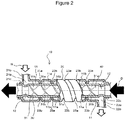
- FIG. 2 is a cross-sectional schematic view for explaining the double-pipe heat exchanger 10 illustrated in FIG. 1 as a first embodiment.
- the double-pipe heat exchanger 10 has an outer pipe 20 and an inner pipe 30 disposed inside of this outer pipe 20, and both the outer pipe 20 and the inner pipe 20 are made of aluminum or aluminum alloy.
- a gap space between an inner peripheral surface of an inner portion of the outer pipe 20 and an outer peripheral surface of the inner pipe 30 is a first refrigerant flow passage (high-pressure refrigerant passage) 11 in which a first refrigerant (high-temperature, high-pressure refrigerant) flows, and an inner space of the inner pipe 30 is a second refrigerant flow passage (low-pressure refrigerant passage) 12 in which a second refrigerant (low-temperature, low-pressure refrigerant) flows.
- the outer pipe 20 is configured with an inlet port 21a into which a high-pressure refrigerant flows, and a high-pressure refrigerant introduction pipe 21b that is connected to the pipe 13b and that introduces the high-pressure refrigerant to the inlet port 21a.
- the outer pipe 20 is also configured with an outlet port 22a from which the high-pressure refrigerant flows out, and a high-pressure refrigerant discharge pipe 22b that introduces the high-pressure refrigerant discharged from the outlet port 22a to the pipe 13c.
- An end portion on the other side (left-hand side in FIG. 2 ) of the outer pipe 20 is a sealing portion 21c that seals an outer periphery of the inner pipe 30, while an end portion on one side (right-hand side in FIG. 2 ) of the outer pipe 20 is a sealing portion 22c that seals the outer periphery of the inner pipe 30.
- a first helical groove 23a and a second helical groove 23b that are of a helical shape and formed recessed toward the inner pipe are formed between the inlet port 21a and the outlet port 22a.
- the first helical groove 23a and the second helical groove 23b are apart equidistantly. Peak portions of the first helical groove 23a and those of the second helical groove 23b abut on the outer peripheral surface of the inner pipe 30.
- the high-pressure refrigerant passage 11 is thereby partitioned into a first high-pressure refrigerant flow passage 11a and a second high-pressure refrigerant flow passage 11b and formed helically around the outer peripheral surface of the inner pipe 30.
- An end portion (not shown) on one side of the inner pipe 30 is connected to the pipe 13e, while an end portion (not shown) on the other side of the inner pipe 30 is connected to the pipe 13f.
- a helical member 40 that helically partitions an internal space 31 of the inner pipe 30 is disposed in this internal space 31.
- the helical member 40 is formed with aluminum or aluminum alloy.
- the helical member 40 is formed with resin such as polypropylene.
- the helical member 40 is formed such that a planar plate member is twisted along an axial direction of the inner pipe 30. End portions of the helical member 40 in a radial direction abut on the inner peripheral surface of the inner pipe 3.
- the internal space 31 of the inner pipe 30 is thereby partitioned into a first helical space 31a and a second helical space 31b each of a helical shape.
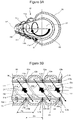
- FIGS. 3A and 3B are explanatory diagrams for explaining flows of the refrigerants flowing in the inner portion of the double-pipe heat exchanger illustrated in FIG. 2 , where FIG. 3A is a perspective view of the double-pipe heat exchanger viewed from a neighborhood on one side to the other side, and FIG. 3B is a partial cross-sectional view of the double-pipe heat exchanger.
- the helical member 40 is not shown.
- the high-pressure refrigerant flowing into the other side of the first refrigerant flow passage (high-pressure refrigerant flow passage) 11 via the high-pressure refrigerant introduction pipe 21b and the inlet port 21a moves in the axial direction of the inner pipe 30 while being revolved helically about the outer periphery of the inner pipe 30 as denoted by dotted lines H1 and H2 and flows toward one side of the high-pressure refrigerant flow passage 11.
- the flow H1 denotes the high-pressure refrigerant flowing in the first high-pressure refrigerant flow passage 11a and the flow H2 denotes the high-pressure refrigerant flowing in the second high-pressure refrigerant flow passage 11b.
- the flows H of the high-pressure refrigerant rotate counterclockwise in a view from one side to the other side of the inner pipe 30 in the axial direction thereof.
- the low-pressure refrigerant flowing into the end portion on one side of the low-pressure refrigerant flow passage 12 moves in the axial direction of the inner pipe 30 while being revolved helically in the internal space 31 of the inner pipe 30 and flows toward the other side of the low-pressure refrigerant flow passage 12 as denoted by a solid line D.
- the flow D of the low-pressure refrigerant rotates clockwise in a view from one side to the other side of the inner pipe 30 in the axial direction thereof.
- a rotation direction of the flows H of the high-pressure refrigerant is opposite to that of the flow D of the low-pressure refrigerant.
- the low-pressure refrigerant flows helically as denoted by the flow D and the high-pressure refrigerant also flows helically as denoted by the flows H1 and H2 and the low-pressure refrigerant and the high-pressure refrigerant are agitated; thus, efficiency of heat exchange of this double-pipe heat exchanger 10 is improved. Furthermore, as illustrated in FIG. 3A , the low-pressure refrigerant flows helically as denoted by the flow D and the high-pressure refrigerant also flows helically as denoted by the flows H1 and H2 and the low-pressure refrigerant and the high-pressure refrigerant are agitated; thus, efficiency of heat exchange of this double-pipe heat exchanger 10 is improved. Furthermore, as illustrated in FIG.
- the double-pipe heat exchanger 10 is configured such that the peaks of the first helical groove 23a and those of the second helical groove 23b abut on the outer peripheral surface of the inner pipe 30; thus, the outer pipe 20 and the inner pipe 30 contact each other entirely in an axial direction of the double-pipe heat exchanger 10 and a mechanical strength can be improved.
- FIG. 3B is a partial cross-sectional view of the double-pipe heat exchanger 10 partially cut to include the axis of the inner pipe, black arrows D1 and D2 denote the flow of the low-pressure refrigerant flowing forward of the helical member 40 on a paper sheet, and dotted arrows H1 and H2 denote the flow of the high-pressure refrigerant flowing forward of the inner pipe 30 on the paper sheet.
- the double-pipe heat exchanger 10 is configured such that first helical abutting lines L1a and L1b that are abutting portions between the peaks of the first helical groove 23a and the second helical groove 23b and the outer peripheral surface of the inner pipe 30 are opposed to second helical abutting lines L2a and L2b that are abutting portions between the helical member 40 and the inner peripheral surface of the inner pipe 30 across the inner pipe 30.
- a helical pitch P1 of the first refrigerant flow passage 11 that is a dimension between the first line L1a out of the first helical abutting lines that is the abutting line between each peak of the first helical groove 23a and the outer peripheral surface of the inner pipe 30 and the second line L1b out of the first helical abutting lines that is the abutting line between each peak of the second helical groove 23b and the outer peripheral surface of the inner pipe 30 is set equivalent to a pitch P2 of the second helical abutting lines that are the abutting lines between the helical member 40 and the inner peripheral surface of the inner pipe 30.
- the flow H1 of the high-pressure refrigerant and the flow D1 of the low-pressure refrigerant are opposed flows and the flow H2 of the high-pressure refrigerant and the flow D2 of the low-pressure refrigerant are opposed flows generally in all courses in which the high-pressure refrigerant and the low-pressure refrigerant flow in the double-pipe heat exchanger 10. It is thus possible to effectively improve the efficiency of heat exchange.
- the double-pipe heat exchanger according to the first embodiment is manufactured as follows. First, a metal plane plate that forms basis for the helical member 40 is twisted or the helical member 40 of the helical shape is prepared by a resin molding process. Next, the helical member 40 is inserted into the inner pipe 30. At this time, an outside diameter of the helical member 40 is preferably slightly larger than a diameter of the inner peripheral surface of the inner pipe 30. After insertion of the helical member 40 into the inner pipe 30, movement of a position of the helical member 40 in a rotation direction thereof can be restricted.
- the inner pipe 30 in the neighborhoods of outer sides of two end portions of the helical member 40 is subjected to a shrinkage process and movement of a position of the helical member 40 in the axial direction thereof is restricted.
- the inner pipe 30, into which the helical member 40 is inserted is inserted into an inner side of the outer pipe 20 in which the inlet port 21a and the outlet port 22a are formed.
- the inner pipe 30 After insertion of the inner pipe 30 into a predetermined position, one end portion and the other end portion of the outer pipe are subjected to a shrinkage process to form the sealing portions 21c and 22c.
- helical grooves are configured in the outer peripheral surface of the outer pipe 30 partially in a depressed fashion using a dedicated tool or device. In this first embodiment, two helical grooves that do not intersect each other are formed.
- the first refrigerant flow passage (high-pressure refrigerant flow passage) 11 is partitioned into the first high-pressure refrigerant flow passage 11a and the second high-pressure refrigerant flow passage 11b.
- the high-pressure refrigerant introduction pipe 21b and the high-pressure refrigerant discharge pipe 22b are mounted in the inlet port 21a and the outlet port 22a, respectively.
- a brazing technique is used for mounting.
- a process for bending the double-pipe heat exchanger may be added before or after mounting the high-pressure refrigerant introduction pipe 21b and the high-pressure refrigerant discharge pipe 22b as needed.
- a material that can resist bending is selected to prevent occurrence of breaking or damage due to the bending.
- aluminum, aluminum alloy, or an elastic material is used for the helical member 40.
- FIGS. 4A and 4B illustrate a double-pipe heat exchanger 110 configured with a third helical groove 23c and a fourth helical groove 23d as an alternative to the first helical groove 23a and the second helical groove 23b formed in the outer pipe 30 in the double-pipe heat exchanger illustrated in FIG. 2 .
- the first refrigerant flow passage (high-pressure refrigerant flow passage) 11 is helically partitioned into a third high-pressure refrigerant flow passage 11c and a fourth high-pressure refrigerant flow passage 11d by the third helical groove 23c and the fourth helical groove 23d.
- the helical member 40 is omitted.
- the high-pressure refrigerant flowing into the other side of the first refrigerant flow passage (high-pressure refrigerant flow passage) 11 via the high-pressure refrigerant introduction pipe 21b and the inlet port 21a moves in the axial direction of the inner pipe 30 while being revolved helically about the outer periphery of the inner pipe 30 as denoted by dotted lines H3 and H4 and flows toward one side of the high-pressure refrigerant flow passage 11.
- the flow H3 denotes the high-pressure refrigerant flowing in the third high-pressure refrigerant flow passage 11c and the flow H4 denotes the high-pressure refrigerant flowing in the fourth high-pressure refrigerant flow passage 11d.
- the flows H of the high-pressure refrigerant rotate clockwise in a view from one side to the other side of the inner pipe 30 in the axial direction thereof.
- the low-pressure refrigerant flows helically as denoted by the flow D and the high-pressure refrigerant also flows helically as denoted by the flows H3 and H4 and the low-pressure refrigerant and the high-pressure refrigerant are agitated; thus, the efficiency of heat exchange of this double-pipe heat exchanger 110 is improved. Furthermore, as illustrated in FIG. 4A , the low-pressure refrigerant flows helically as denoted by the flow D and the high-pressure refrigerant also flows helically as denoted by the flows H3 and H4 and the low-pressure refrigerant and the high-pressure refrigerant are agitated; thus, the efficiency of heat exchange of this double-pipe heat exchanger 110 is improved. Furthermore, as illustrated in FIG.
- the double-pipe heat exchanger 110 is configured such that peaks of the third helical groove 23c and those of the fourth helical groove 23d abut on the outer peripheral surface of the inner pipe 30; thus, the outer pipe 20 and the inner pipe 30 contact each other entirely in an axial direction of the double-pipe heat exchanger 110 and a mechanical strength can be, therefore, improved.
- FIG. 4B is a cross-sectional view illustrating part of the double-pipe heat exchanger 110, the black arrows D1 and D2 denote the flow of the low-pressure refrigerant flowing forward of the helical member 40 on a paper sheet, and dotted arrows H3 and H4 denote the flow of the high-pressure refrigerant flowing forward of the inner pipe 30 on the paper sheet.
- a helical pitch P3 of the first refrigerant flow passage 11 that is a dimension between a first line L3a out of third helical abutting lines that is the abutting line between each peak of the third helical groove 23c and the outer peripheral surface of the inner pipe 30 and the second line L1b out of the first helical abutting lines that is the abutting line between each peak of the second helical groove 23b and the outer peripheral surface of the inner pipe 30 is set equivalent to the pitch P2 of the second helical abutting lines that are the abutting lines between the helical member 40 and the inner peripheral surface of the inner pipe 30.
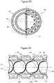
- FIG. 5A is a schematic cross-sectional view of the double-pipe heat exchanger 110 according to the second embodiment cut perpendicularly to the axis of the inner pipe 30 and viewed from one side to the other side.
- FIG. 5B is a partial cross-sectional view of this double-pipe heat exchanger 110 cut to include the axis of the inner pipe.
- structures of the third helical abutting lines (L3a and L3b) and the second helical abutting lines (L2a and L2b) on a thick dotted line M illustrated in FIG. 5A will be described.
- the first line L3a out of the third helical abutting lines that is the abutting line between each peak of the third helical groove 23c and the outer peripheral surface of the inner pipe 30 and the second line L3b out of the third helical abutting lines that is the abutting line between each peak of the fourth helical groove 23d and the outer peripheral surface of the inner pipe 30 are denoted by thick dotted lines .
- the second helical abutting lines L2a and L2b that are the abutting lines between the helical member 40 and the inner peripheral surface of the inner pipe 30 are denoted by thick solid lines.
- the third helical abutting lines L3a and L3b intersect the second helical abutting lines L2a and L2b.
- the third helical abutting lines L3a and L3b that are portions in which the outer pipe 20 abuts on the inner pipe 30 to intersect the second helical abutting lines L2a and L2b that are portions in which the helical member 40 abuts on the inner pipe 30 makes it possible to more reliably improve a mechanical strength of the double-pipe heat exchanger 110.
- a third embodiment will next be described with reference to FIG. 6 .
- a double-pipe heat exchanger 210 in this embodiment is similarly configured with the outer pipe 20, the inner pipe 30, and a helical member 240 that is disposed in the internal space of the inner pipe and that helically partitions the internal space.
- the first helical groove 23a and the second helical groove 23b that are of the helical shape and formed recessed toward the inner pipe are formed between the inlet port 21a and the outlet port 22a.
- the first helical groove 23a and the second helical groove 23b of the helical shape are not formed entirely between the inlet port 21a and the outlet port 22a and not formed in portions proximate to the outlet port 22a.
- the high-pressure refrigerant H flowing from the inlet port 21a flows first as a helical flow H5 since the high-pressure refrigerant passage 11 is helically partitioned by the first helical groove 23a and the second helical groove 23b in the vicinity of the inlet port 21a.
- the high-pressure refrigerant H flows as a helical flow H6 that is a flow toward the helical outlet port 22a along the axial direction, compared with the helical flow H5, while keeping an impetus of the helical flow (impetus of the flow in a circumferential direction) to a certain extent.
- the high-pressure refrigerant flowing from the inlet port 21a flows toward the outlet port 22a while the high-pressure refrigerant is agitated and an increase in a passage resistance is suppressed.
- the helical member 240 disposed in the internal space of the inner pipe 30 has a length in a direction along the axial direction sufficiently smaller than a length of the inner pipe 30 in the axial direction and is disposed in the vicinity of the end portion on one side of the inner pipe 30.
- the helical member 240 is preferably configured such that the low-pressure refrigerant flowing from the end portion on one side of the inner pipe 30 rotates 180° or more. If the helical member 240 is configured such that the low-pressure refrigerant rotates less than 180°, components of the low-pressure refrigerant flowing from the end portion on one side of the inner pipe 30 and flowing linearly in the axial direction of the inner pipe remain, possibly resulting in an inefficient agitation effect.
- the low-pressure refrigerant D flows into the inner pipe 30, in which such a short helical member 240 is disposed, from one side, the low-pressure refrigerant D flows first as a helical flow D2.
- the low-pressure refrigerant passing through the helical member 240 flows toward the other side of the inner pipe while the impetus of the helical flow (flow of the impetus in the circumferential direction) is kept to a certain extent and a flow direction of the helical flow is gradually changed to the direction along the axial direction of the inner pipe 30 as denoted by helical flows D3 and D4.
- the high/low-pressure refrigerant flowing from one side (right-hand side in FIG. 6 ) flows toward the other side (left-hand side in FIG. 6 ) while the low-pressure refrigerant is agitated and the increase in the passage resistance is suppressed.
- the double-pipe heat exchanger 210 according to the third embodiment can suppress the increase in the passage resistance while improving the efficiency of heat exchange.
- a fourth embodiment will next be described with reference to FIG. 7 .
- a double-pipe heat exchanger 310 in this embodiment is similarly configured with the outer pipe 20, the inner pipe 30, and a helical member 340 that is disposed in the internal space of the inner pipe and that helically partitions the internal space.
- the first helical groove 23a and the second helical groove 23b that are of the helical shape and formed recessed toward the inner pipe are formed between the inlet port 21a and the outlet port 22a.
- the first helical groove 23a and the second helical groove 23b of the helical shape are not formed entirely between the inlet port 21a and the outlet port 22a and not formed in portions proximate to the outlet port 22a. So far, the fourth embodiment is similar to the third embodiment.
- the first helical groove 23a and the second helical groove 23b of the helical shape are formed as a first helical groove 23a' and a second helical groove 23b' having peak portions apart from the outer peripheral surface of the inner pipe 30 in an intermediate location between the inlet port 21a and the outlet port 22a of the outer pipe 20 (which means not only the intermediate location in a strict sense but also neighborhoods of a central portion of the double-pipe heat exchanger in the axial direction thereof) .
- the high-pressure refrigerant H flowing from the inlet port 21a flows first as a helical flow H7 since the high-pressure refrigerant passage 11 is helically partitioned by the first helical groove 23a and the second helical groove 23b in the vicinity of the inlet port 21a.
- the high-pressure refrigerant H flows as a helical flow H8 generally equivalent in helical direction to the helical flow H7 but smaller in flow rate than the helical flow H7 and as an axial flow H9 flowing in gaps between the peak portions of the first helical groove 23a' and of the second helical groove 23b' and the outer peripheral surface of the inner pipe 30.
- the high-pressure refrigerant H flows as a helical flow H10 that is a flow toward the helical outlet port 22a along the axial direction, compared with the helical flow H8, while keeping the impetus of the helical flow (impetus of the flow in the circumferential direction) to a certain extent. Even with such a configuration, the high-pressure refrigerant H can flow while the impetus of the helical flow is kept to a certain extent and an increase in the passage resistance of the high-pressure refrigerant H can be suppressed.
- the helical member 340 disposed in the internal space of the inner pipe 30 has a length in a direction along the axial direction sufficiently smaller than the length of the inner pipe 30 in the axial direction and is disposed in the vicinity of the end portion on one side of the inner pipe 30.
- a diameter of the helical member 340 is formed such that the low-pressure refrigerant D flowing from the end portion on one side of the inner pipe 30 rotates 180° or more and that the diameter then gradually decreases toward the other side.
- the low-pressure refrigerant D flowing from the end portion on one side of the inner pipe 30 flows as a helical flow D5 and then flows toward the other side of the inner pipe while a flow direction of the helical flow is gradually changed to the direction along the axial direction of the inner pipe 30 as denoted by helical flows D6 and D7. Even with such a configuration, the low-pressure refrigerant can flow while the impetus of the helical flow is kept to a certain extent and an increase in the passage resistance of the low-pressure refrigerant D can be suppressed.
- a helical fin (not shown) that helically partitions a space of this high-pressure refrigerant passage 11 and that is a separate member from the outer pipe 20 and the inner pipe 30 may be disposed in the high-pressure refrigerant passage 11. This can dispense with a process for forming the first helical groove 23a and the second helical groove 23b in the outer pipe 30.
- the vehicle air conditioner according to the present invention can be manufactured industrially and can be handled as an object for commercial trading, the vehicle air conditioner according to the present invention is of economic value and industrially available.
Landscapes
- Engineering & Computer Science (AREA)
- Physics & Mathematics (AREA)
- Thermal Sciences (AREA)
- Mechanical Engineering (AREA)
- General Engineering & Computer Science (AREA)
- Geometry (AREA)
- Heat-Exchange Devices With Radiators And Conduit Assemblies (AREA)
Abstract
Description
- The present invention relates to a double-pipe heat exchanger disposed in a refrigeration cycle of a vehicle air conditioner.
- As disclosed in
Patent Literatures 1 and 2, a double pipe (double-pipe heat exchanger) that has an inner pie and an outer pipe disposed outside of this inner pipe and that transfers heat between a low-temperature, low-pressure refrigerant flowing to an inner side of the inner pipe and a high-temperature, high-pressure refrigerant flowing between an outer peripheral surface of the inner pipe and an inner peripheral surface of the outer pipe has been conventionally known as a device that enhances the cooling capacity of a refrigeration cycle of a vehicle air conditioner. - The double pipe disclosed in
Patent Literature 1 is configured such that a helical fin is inserted into the inner pipe and the low-temperature, low-pressure refrigerant is helically revolved and agitated when the low-temperature, low-pressure refrigerant flows in the fin, and indicates that the efficiency of heat exchange between the low-temperature, low-pressure refrigerant and the high-temperature, high-pressure refrigerant can be improved. - The double pipe disclosed in Patent Literature 2 is configured such that a helical groove is formed in the inner pipe, ridge portions into which the groove is partitioned abut on the inner peripheral surface of the outer pipe, the high-temperature, high-pressure refrigerant is helically revolved and agitated when the high-temperature, high-pressure refrigerant flows between the outer peripheral surface of the inner pipe and the inner peripheral surface of the outer pipe, and indicates that the efficiency of heat exchange between the high-temperature, high-pressure refrigerant and the low-temperature, low-pressure refrigerant can be improved.
- Patent Literature 1:
JP-A-2018-021699 - Patent Literature 2:
JP-A-2006-162241 - However, the double pipe disclosed in
Patent Literature 1 is unable to agitate the refrigerant flowing between the outer peripheral surface of the inner pipe and the inner peripheral surface of the outer pipe while the double pipe can agitate the refrigerant flowing in an inner portion of the inner pipe; thus, the double pipe has room for improvement in the efficiency of heat exchange. - Furthermore, the double pipe disclosed in Patent Literature 2 enables the refrigerant flowing in an inner portion of the inner pipe to flow in such a manner as to produce a short-circuit in an axial direction of the double pipe while the double pipe can agitate the refrigerant flowing between the outer peripheral surface of the inner pipe and the inner peripheral surface of the outer pipe; thus, the double pipe can agitate the refrigerant only insufficiently and has room for improvement in the efficiency of heat exchange.
- Meanwhile, a heat exchanger in which the high-temperature, high-pressure refrigerant flows is a pressure chamber which is a tubular body; thus, an overall shape of the heat exchanger is long and thin and the heat exchanger is required to improve a strength as a structure.
- An object of the present invention is, therefore, to provide a double pipe that can reliably agitate a flowing refrigerant to improve efficiency of heat exchange and that can improve a structural strength.
- According to a preferred embodiment of the present invention, provided is a double-pipe heat exchanger including: an outer pipe; an inner pipe disposed an inner portion of the outer pipe; and a helical member that is disposed in an internal space of the inner pipe and that helically partitions the internal space, wherein a gap space between an inner peripheral surface in the inner portion of the outer pipe and an outer peripheral surface of the inner pipe is a first refrigerant flow passage, the internal space of the inner pipe is a second refrigerant flow passage, a refrigerant flowing in the first refrigerant flow passage flows into the first refrigerant flow passage from the other side of the inner pipe in an axial direction of the inner pipe and then flows out from one side, a refrigerant flowing in the second refrigerant flow passage flows into the second refrigerant flow passage from the one side of the inner pipe in the axial direction and then flows out from the other side, and the first refrigerant flow passage is helically partitioned.
- Therefore, not only the refrigerant flowing in the second refrigerant flow passage but also the refrigerant flowing in the first refrigerant flow passage flows while helically rotating; thus, the two refrigerants are agitated and the efficiency of heat exchange is improved. Moreover, not only the helical member is disposed in the second refrigerant flow passage but also the first refrigerant flow passage is helically partitioned so that the first refrigerant flow passage has a helical shape; thus, the structure is strengthened.
- Furthermore, the double-pipe heat exchanger is preferably configured such that in a view from the one side to the other side of the
inner pipe 30 in the axial direction, a helical rotation direction of the refrigerant flowing in the first refrigerant flow passage is opposite to a helical rotation direction of the refrigerant flowing in the second refrigerant flow passage. In the double pipe, the refrigerant flowing in the first refrigerant flow passage and the refrigerant flowing in the second refrigerant flow passage flow while being opposed to each other; thus, the efficiency of heat exchange is further improved. - Moreover, the double-pipe heat exchanger is preferably configured such that in the axial direction of the inner pipe, a helical pitch of the first refrigerant flow passage is equal to a helical pitch of the helical member. Rationally causing the first refrigerant flow passage and the second refrigerant flow passage to be opposed to each other makes it possible to improve the efficiency of heat exchange.
- Furthermore, the double-pipe heat exchanger is preferably configured such that first helical abutting lines that are abutting portions between helical grooves helically partitioning the first refrigerant flow passage and the outer peripheral surface of the inner pipe are opposed to second helical abutting lines that are abutting portions between the helical member and an inner peripheral surface of the inner pipe across the inner pipe. Rationally causing the first refrigerant flow passage and the second refrigerant flow passage to be opposed to each other makes it possible to improve the efficiency of heat exchange.
- Moreover, the double-pipe heat exchanger may be configured such that in a view from the one side to the other side of the
inner pipe 30 in the axial direction, a helical rotation direction of the refrigerant flowing in the first refrigerant flow passage is equal to a helical rotation direction of the refrigerant flowing in the second refrigerant flow passage. Since the double-pipe heat exchanger can be configured such that the first refrigerant flow passage intersects the second refrigerant flow passage, it is possible to strengthen the structure of the double pipe while improving the efficiency of heat exchange between the refrigerant flowing in the first refrigerant flow passage and the refrigerant flowing in the second refrigerant flow passage. - According to the embodiment of the present invention, it is possible to provide the double pipe heat exchanger that can reliably agitate the flowing refrigerants to improve the efficiency of heat exchange and that can improve a structural strength.
-
-
FIG. 1 is a schematic configuration diagram illustrating a refrigeration cycle of a vehicle air conditioner in which a double-pipe heat exchanger according to an embodiment of the present invention is disposed. -
FIG. 2 is a schematic cross-sectional view of the double-pipe heat exchanger according to a first embodiment. -
FIGS. 3A and 3B are explanatory diagrams for explaining flows of refrigerants flowing in an inner portion of the double-pipe heat exchanger according to the first embodiment, whereFIG. 3A is a perspective view of the double-pipe heat exchanger viewed from a neighborhood on one side to the other side andFIG. 3B is a partial cross-sectional view of the double-pipe heat exchanger cut to include an axis of an inner pipe. -
FIGS. 4A and 4B are explanatory diagrams for explaining flows of refrigerants flowing in an inner portion of a double-pipe heat exchanger according to a second embodiment, whereFIG. 4A is a perspective view of the double-pipe heat exchanger viewed from a neighborhood on one side to the other side andFIG. 4B is a partial cross-sectional view of the double-pipe heat exchanger cut to include an axis of an inner pipe. -
FIGS. 5A and 5B are explanatory diagrams for explaining a structure of the double-pipe heat exchanger according to the second embodiment, whereFIG. 5A is a schematic cross-sectional view of the double-pipe heat exchanger cut perpendicularly to the axis of the inner pipe and viewed from one side to the other side, andFIG. 5B is a partial cross-sectional view of the double-pipe heat exchanger cut to include the axis of the inner pipe. -
FIG. 6 is a schematic cross-sectional view of a double-pipe heat exchanger according to a third embodiment. -
FIG. 7 is a schematic cross-sectional view of a double-pipe heat exchanger according to a fourth embodiment. - Embodiments of a double-pipe heat exchanger according to the present invention will be described hereinafter with reference to the drawings. The embodiments described hereinafter are embodiments of the present invention and the present invention is not limited to the following embodiments . It is assumed that constituent elements denoted by the same reference symbols and signs in the present specification and the drawings are mutually identical. Various modifications may be made as long as advantages of the present invention can be exhibited.
-
FIG. 1 is a schematic configuration diagram illustrating arefrigeration cycle 1 of a vehicle air conditioner in which a double-pipe heat exchanger 10 according to an embodiment of the present invention is disposed. - In the
refrigeration cycle 1 configured in this way, when a compressor 2 is activated, then a high-temperature, high-pressure refrigerant is delivered and arrives at an expanding device 4 by way of acondenser 3 and a high-pressure refrigerant passage 11 of the double-pipe heat exchanger 10 along a flow denoted by white arrows inFIG. 1 . The refrigerant expanded by the expanding device 4 is made into a low-temperature, low-pressure refrigerant and the low-temperature, low-pressure refrigerant arrives at the compressor 2 by way of an evaporator 5, a low-pressure refrigerant passage 12 of the double-pipe heat exchanger 10, and an accumulator 6 along a flow denoted by black arrows inFIG. 1 . The double-pipe heat exchanger 10 is a member that transfers heat between the high-temperature, high-pressure refrigerant and the low-temperature, low-pressure refrigerant circulating in an inner portion of therefrigeration cycle 1 and is often referred to as an "internal heat exchanger". -
FIG. 1 illustrates an example of therefrigeration cycle 1 of the vehicle air conditioner in which the double-pipe heat exchanger 10 described below is disposed. - The
refrigeration cycle 1 has the compressor 2 that compresses the refrigerant, thecondenser 3 that cools the refrigerant compressed by this compressor 2, the expanding device 4 that reduces the pressure of the refrigerant flowing out from thiscondenser 3 and that expands the refrigerant, the evaporator 5 that evaporates the refrigerant the pressure of which is reduced by this expanding device 4, and the accumulator 6 that separates the refrigerant flowing out from this evaporator 5 into a gaseous refrigerant and a liquid refrigerant and that discharges the gaseous refrigerant. Furthermore, the double-pipe heat exchanger 10 configured with the high-pressure refrigerant passage 11 in which a refrigerant flows from thecondenser 3 to the expanding device 4 and the low-pressure refrigerant passage 12 in which a refrigerant flows from the evaporator 5 to the accumulator 6 is disposed in thisrefrigeration cycle 1. Disposing the double-pipe heat exchanger 10 makes it possible to reduce an enthalpy of the refrigerant flowing into the evaporator 5 and to enhance a cooling capacity of therefrigeration cycle 1. - The
refrigeration cycle 1 is configured to be able to circulate the refrigerants by being configured with apipe 13a that connects the compressor 2 to thecondenser 3 either directly or indirectly, apipe 13b that connects thecondenser 3 to the high-pressure refrigerant passage 11 of the double-pipe heat exchanger 10 either directly or indirectly, apipe 13c that connects the high-pressure refrigerant passage 11 of the double-pipe heat exchanger 10 to the expanding device 4 either directly or indirectly, apipe 13d that connects the expanding device 4 to the evaporator 5 either directly or indirectly, apipe 13e that connects the evaporator 5 to the low-pressure refrigerant passage 12 of the double-pipe heat exchanger 10 either directly or indirectly, apipe 13f that connects the low-pressure refrigerant passage 12 of the double-pipe heat exchanger 10 to the accumulator 6 either directly or indirectly, and apipe 13g that connects the accumulator 6 to the compressor 2 either directly or indirectly. While the accumulator 6 is illustrated in this embodiment as a member that separates the refrigerant into a gaseous refrigerant and a liquid refrigerant, a liquid tank may be disposed between thecondenser 3 and the high-pressure refrigerant passage 11 of the double-pipe heat exchanger 10 as an alternative to the accumulator 6. Furthermore, while it is described that therefrigeration cycle 1 has a structure configured with thepipe 13d between the expanding device 4 and the evaporator 5, thepipe 13d may be omitted and the expanding device 4 may be directly connected to the evaporator 5. -
FIG. 2 is a cross-sectional schematic view for explaining the double-pipe heat exchanger 10 illustrated inFIG. 1 as a first embodiment. The double-pipe heat exchanger 10 has anouter pipe 20 and aninner pipe 30 disposed inside of thisouter pipe 20, and both theouter pipe 20 and theinner pipe 20 are made of aluminum or aluminum alloy. A gap space between an inner peripheral surface of an inner portion of theouter pipe 20 and an outer peripheral surface of theinner pipe 30 is a first refrigerant flow passage (high-pressure refrigerant passage) 11 in which a first refrigerant (high-temperature, high-pressure refrigerant) flows, and an inner space of theinner pipe 30 is a second refrigerant flow passage (low-pressure refrigerant passage) 12 in which a second refrigerant (low-temperature, low-pressure refrigerant) flows. - The
outer pipe 20 is configured with aninlet port 21a into which a high-pressure refrigerant flows, and a high-pressurerefrigerant introduction pipe 21b that is connected to thepipe 13b and that introduces the high-pressure refrigerant to theinlet port 21a. Theouter pipe 20 is also configured with anoutlet port 22a from which the high-pressure refrigerant flows out, and a high-pressurerefrigerant discharge pipe 22b that introduces the high-pressure refrigerant discharged from theoutlet port 22a to thepipe 13c. An end portion on the other side (left-hand side inFIG. 2 ) of theouter pipe 20 is a sealingportion 21c that seals an outer periphery of theinner pipe 30, while an end portion on one side (right-hand side inFIG. 2 ) of theouter pipe 20 is a sealingportion 22c that seals the outer periphery of theinner pipe 30. - A first
helical groove 23a and a secondhelical groove 23b that are of a helical shape and formed recessed toward the inner pipe are formed between theinlet port 21a and theoutlet port 22a. The firsthelical groove 23a and the secondhelical groove 23b are apart equidistantly. Peak portions of the firsthelical groove 23a and those of the secondhelical groove 23b abut on the outer peripheral surface of theinner pipe 30. The high-pressure refrigerant passage 11 is thereby partitioned into a first high-pressurerefrigerant flow passage 11a and a second high-pressurerefrigerant flow passage 11b and formed helically around the outer peripheral surface of theinner pipe 30. - An end portion (not shown) on one side of the
inner pipe 30 is connected to thepipe 13e, while an end portion (not shown) on the other side of theinner pipe 30 is connected to thepipe 13f. - A
helical member 40 that helically partitions aninternal space 31 of theinner pipe 30 is disposed in thisinternal space 31. Thehelical member 40 is formed with aluminum or aluminum alloy. Alternatively, thehelical member 40 is formed with resin such as polypropylene. Thehelical member 40 is formed such that a planar plate member is twisted along an axial direction of theinner pipe 30. End portions of thehelical member 40 in a radial direction abut on the inner peripheral surface of theinner pipe 3. Theinternal space 31 of theinner pipe 30 is thereby partitioned into a firsthelical space 31a and a secondhelical space 31b each of a helical shape. -
FIGS. 3A and 3B are explanatory diagrams for explaining flows of the refrigerants flowing in the inner portion of the double-pipe heat exchanger illustrated inFIG. 2 , whereFIG. 3A is a perspective view of the double-pipe heat exchanger viewed from a neighborhood on one side to the other side, andFIG. 3B is a partial cross-sectional view of the double-pipe heat exchanger. - In
FIG. 3A , thehelical member 40 is not shown. The high-pressure refrigerant flowing into the other side of the first refrigerant flow passage (high-pressure refrigerant flow passage) 11 via the high-pressurerefrigerant introduction pipe 21b and theinlet port 21a moves in the axial direction of theinner pipe 30 while being revolved helically about the outer periphery of theinner pipe 30 as denoted by dotted lines H1 and H2 and flows toward one side of the high-pressurerefrigerant flow passage 11. The flow H1 denotes the high-pressure refrigerant flowing in the first high-pressurerefrigerant flow passage 11a and the flow H2 denotes the high-pressure refrigerant flowing in the second high-pressurerefrigerant flow passage 11b. In an example ofFIG. 3A , the flows H of the high-pressure refrigerant rotate counterclockwise in a view from one side to the other side of theinner pipe 30 in the axial direction thereof. - On the other hand, in the
inner pipe 30, the low-pressure refrigerant flowing into the end portion on one side of the low-pressurerefrigerant flow passage 12 moves in the axial direction of theinner pipe 30 while being revolved helically in theinternal space 31 of theinner pipe 30 and flows toward the other side of the low-pressurerefrigerant flow passage 12 as denoted by a solid line D. In the example ofFIG. 3A , the flow D of the low-pressure refrigerant rotates clockwise in a view from one side to the other side of theinner pipe 30 in the axial direction thereof. In other words, a rotation direction of the flows H of the high-pressure refrigerant is opposite to that of the flow D of the low-pressure refrigerant. - In
FIG. 3A , the low-pressure refrigerant flows helically as denoted by the flow D and the high-pressure refrigerant also flows helically as denoted by the flows H1 and H2 and the low-pressure refrigerant and the high-pressure refrigerant are agitated; thus, efficiency of heat exchange of this double-pipe heat exchanger 10 is improved. Furthermore, as illustrated inFIG. 3B , the double-pipe heat exchanger 10 is configured such that the peaks of the firsthelical groove 23a and those of the secondhelical groove 23b abut on the outer peripheral surface of theinner pipe 30; thus, theouter pipe 20 and theinner pipe 30 contact each other entirely in an axial direction of the double-pipe heat exchanger 10 and a mechanical strength can be improved. -
FIG. 3B is a partial cross-sectional view of the double-pipe heat exchanger 10 partially cut to include the axis of the inner pipe, black arrows D1 and D2 denote the flow of the low-pressure refrigerant flowing forward of thehelical member 40 on a paper sheet, and dotted arrows H1 and H2 denote the flow of the high-pressure refrigerant flowing forward of theinner pipe 30 on the paper sheet. The double-pipe heat exchanger 10 is configured such that first helical abutting lines L1a and L1b that are abutting portions between the peaks of the firsthelical groove 23a and the secondhelical groove 23b and the outer peripheral surface of theinner pipe 30 are opposed to second helical abutting lines L2a and L2b that are abutting portions between thehelical member 40 and the inner peripheral surface of theinner pipe 30 across theinner pipe 30. Furthermore, a helical pitch P1 of the firstrefrigerant flow passage 11 that is a dimension between the first line L1a out of the first helical abutting lines that is the abutting line between each peak of the firsthelical groove 23a and the outer peripheral surface of theinner pipe 30 and the second line L1b out of the first helical abutting lines that is the abutting line between each peak of the secondhelical groove 23b and the outer peripheral surface of theinner pipe 30 is set equivalent to a pitch P2 of the second helical abutting lines that are the abutting lines between thehelical member 40 and the inner peripheral surface of theinner pipe 30. - As illustrated in
FIG. 3B , the flow H1 of the high-pressure refrigerant and the flow D1 of the low-pressure refrigerant are opposed flows and the flow H2 of the high-pressure refrigerant and the flow D2 of the low-pressure refrigerant are opposed flows generally in all courses in which the high-pressure refrigerant and the low-pressure refrigerant flow in the double-pipe heat exchanger 10. It is thus possible to effectively improve the efficiency of heat exchange. - Configuring the double-pipe heat exchanger such that the first helical abutting lines L1a and L1b are opposed to the second helical abutting lines L2a and L2b across the
inner pipe 30, in particular, makes it possible to oppose the high-pressure refrigerant flow passage to the low-pressure refrigerant flow passage, to make smooth the movement of relatively low heat TC to the high-pressure refrigerant and movement of relatively high heat TW to the low-pressure refrigerant, and to effectively improve the efficiency of heat exchange. - The double-pipe heat exchanger according to the first embodiment is manufactured as follows. First, a metal plane plate that forms basis for the
helical member 40 is twisted or thehelical member 40 of the helical shape is prepared by a resin molding process. Next, thehelical member 40 is inserted into theinner pipe 30. At this time, an outside diameter of thehelical member 40 is preferably slightly larger than a diameter of the inner peripheral surface of theinner pipe 30. After insertion of thehelical member 40 into theinner pipe 30, movement of a position of thehelical member 40 in a rotation direction thereof can be restricted. After insertion of thehelical member 40 into theinner pipe 30, theinner pipe 30 in the neighborhoods of outer sides of two end portions of thehelical member 40 is subjected to a shrinkage process and movement of a position of thehelical member 40 in the axial direction thereof is restricted. - Next, the
inner pipe 30, into which thehelical member 40 is inserted, is inserted into an inner side of theouter pipe 20 in which theinlet port 21a and theoutlet port 22a are formed. After insertion of theinner pipe 30 into a predetermined position, one end portion and the other end portion of the outer pipe are subjected to a shrinkage process to form the sealingportions outer pipe 30 partially in a depressed fashion using a dedicated tool or device. In this first embodiment, two helical grooves that do not intersect each other are formed. Through this process, the first refrigerant flow passage (high-pressure refrigerant flow passage) 11 is partitioned into the first high-pressurerefrigerant flow passage 11a and the second high-pressurerefrigerant flow passage 11b. - Finally, the high-pressure
refrigerant introduction pipe 21b and the high-pressurerefrigerant discharge pipe 22b are mounted in theinlet port 21a and theoutlet port 22a, respectively. For example, a brazing technique is used for mounting. A process for bending the double-pipe heat exchanger may be added before or after mounting the high-pressurerefrigerant introduction pipe 21b and the high-pressurerefrigerant discharge pipe 22b as needed. However, a material that can resist bending is selected to prevent occurrence of breaking or damage due to the bending. For example, aluminum, aluminum alloy, or an elastic material is used for thehelical member 40. - While the first embodiment of the present invention has been described so far, a second embodiment will be described with reference to
FIGS. 4A and 4B . -
FIGS. 4A and 4B illustrate a double-pipe heat exchanger 110 configured with a thirdhelical groove 23c and a fourthhelical groove 23d as an alternative to the firsthelical groove 23a and the secondhelical groove 23b formed in theouter pipe 30 in the double-pipe heat exchanger illustrated inFIG. 2 . As illustrated inFIG. 4B , the first refrigerant flow passage (high-pressure refrigerant flow passage) 11 is helically partitioned into a third high-pressurerefrigerant flow passage 11c and a fourth high-pressurerefrigerant flow passage 11d by the thirdhelical groove 23c and the fourthhelical groove 23d. - Similarly in
FIG. 4A , thehelical member 40 is omitted. The high-pressure refrigerant flowing into the other side of the first refrigerant flow passage (high-pressure refrigerant flow passage) 11 via the high-pressurerefrigerant introduction pipe 21b and theinlet port 21a moves in the axial direction of theinner pipe 30 while being revolved helically about the outer periphery of theinner pipe 30 as denoted by dotted lines H3 and H4 and flows toward one side of the high-pressurerefrigerant flow passage 11. The flow H3 denotes the high-pressure refrigerant flowing in the third high-pressurerefrigerant flow passage 11c and the flow H4 denotes the high-pressure refrigerant flowing in the fourth high-pressurerefrigerant flow passage 11d. In an example ofFIG. 4A , the flows H of the high-pressure refrigerant rotate clockwise in a view from one side to the other side of theinner pipe 30 in the axial direction thereof. - Similarly in
FIG. 4A , the low-pressure refrigerant flows helically as denoted by the flow D and the high-pressure refrigerant also flows helically as denoted by the flows H3 and H4 and the low-pressure refrigerant and the high-pressure refrigerant are agitated; thus, the efficiency of heat exchange of this double-pipe heat exchanger 110 is improved. Furthermore, as illustrated inFIG. 4B , the double-pipe heat exchanger 110 is configured such that peaks of the thirdhelical groove 23c and those of the fourthhelical groove 23d abut on the outer peripheral surface of theinner pipe 30; thus, theouter pipe 20 and theinner pipe 30 contact each other entirely in an axial direction of the double-pipe heat exchanger 110 and a mechanical strength can be, therefore, improved. -
FIG. 4B is a cross-sectional view illustrating part of the double-pipe heat exchanger 110, the black arrows D1 and D2 denote the flow of the low-pressure refrigerant flowing forward of thehelical member 40 on a paper sheet, and dotted arrows H3 and H4 denote the flow of the high-pressure refrigerant flowing forward of theinner pipe 30 on the paper sheet. A helical pitch P3 of the firstrefrigerant flow passage 11 that is a dimension between a first line L3a out of third helical abutting lines that is the abutting line between each peak of the thirdhelical groove 23c and the outer peripheral surface of theinner pipe 30 and the second line L1b out of the first helical abutting lines that is the abutting line between each peak of the secondhelical groove 23b and the outer peripheral surface of theinner pipe 30 is set equivalent to the pitch P2 of the second helical abutting lines that are the abutting lines between thehelical member 40 and the inner peripheral surface of theinner pipe 30. -
FIG. 5A is a schematic cross-sectional view of the double-pipe heat exchanger 110 according to the second embodiment cut perpendicularly to the axis of theinner pipe 30 and viewed from one side to the other side. Furthermore,FIG. 5B is a partial cross-sectional view of this double-pipe heat exchanger 110 cut to include the axis of the inner pipe. With reference toFIG. 5B , structures of the third helical abutting lines (L3a and L3b) and the second helical abutting lines (L2a and L2b) on a thick dotted line M illustrated inFIG. 5A will be described. - In
FIG. 5B , the first line L3a out of the third helical abutting lines that is the abutting line between each peak of the thirdhelical groove 23c and the outer peripheral surface of theinner pipe 30 and the second line L3b out of the third helical abutting lines that is the abutting line between each peak of the fourthhelical groove 23d and the outer peripheral surface of theinner pipe 30 are denoted by thick dotted lines . In addition, inFIG. 5B , the second helical abutting lines L2a and L2b that are the abutting lines between thehelical member 40 and the inner peripheral surface of theinner pipe 30 are denoted by thick solid lines. As can be understood fromFIG. 5B , the third helical abutting lines L3a and L3b intersect the second helical abutting lines L2a and L2b. In this way, causing the third helical abutting lines L3a and L3b that are portions in which theouter pipe 20 abuts on theinner pipe 30 to intersect the second helical abutting lines L2a and L2b that are portions in which thehelical member 40 abuts on theinner pipe 30 makes it possible to more reliably improve a mechanical strength of the double-pipe heat exchanger 110. - A third embodiment will next be described with reference to
FIG. 6 . - A double-
pipe heat exchanger 210 in this embodiment is similarly configured with theouter pipe 20, theinner pipe 30, and ahelical member 240 that is disposed in the internal space of the inner pipe and that helically partitions the internal space. - The first
helical groove 23a and the secondhelical groove 23b that are of the helical shape and formed recessed toward the inner pipe are formed between theinlet port 21a and theoutlet port 22a. Here, the firsthelical groove 23a and the secondhelical groove 23b of the helical shape are not formed entirely between theinlet port 21a and theoutlet port 22a and not formed in portions proximate to theoutlet port 22a. Owing to this, the high-pressure refrigerant H flowing from theinlet port 21a flows first as a helical flow H5 since the high-pressure refrigerant passage 11 is helically partitioned by the firsthelical groove 23a and the secondhelical groove 23b in the vicinity of theinlet port 21a. Next, after passing through helical grooves 23ae and 23be farthest from theinlet port 21a, the high-pressure refrigerant H flows as a helical flow H6 that is a flow toward thehelical outlet port 22a along the axial direction, compared with the helical flow H5, while keeping an impetus of the helical flow (impetus of the flow in a circumferential direction) to a certain extent. In other words, the high-pressure refrigerant flowing from theinlet port 21a flows toward theoutlet port 22a while the high-pressure refrigerant is agitated and an increase in a passage resistance is suppressed. - The
helical member 240 disposed in the internal space of theinner pipe 30 has a length in a direction along the axial direction sufficiently smaller than a length of theinner pipe 30 in the axial direction and is disposed in the vicinity of the end portion on one side of theinner pipe 30. Thehelical member 240 is preferably configured such that the low-pressure refrigerant flowing from the end portion on one side of theinner pipe 30 rotates 180° or more. If thehelical member 240 is configured such that the low-pressure refrigerant rotates less than 180°, components of the low-pressure refrigerant flowing from the end portion on one side of theinner pipe 30 and flowing linearly in the axial direction of the inner pipe remain, possibly resulting in an inefficient agitation effect. - When the low-pressure refrigerant D flows into the
inner pipe 30, in which such a shorthelical member 240 is disposed, from one side, the low-pressure refrigerant D flows first as a helical flow D2. Next, the low-pressure refrigerant passing through thehelical member 240 flows toward the other side of the inner pipe while the impetus of the helical flow (flow of the impetus in the circumferential direction) is kept to a certain extent and a flow direction of the helical flow is gradually changed to the direction along the axial direction of theinner pipe 30 as denoted by helical flows D3 and D4. In other words, the high/low-pressure refrigerant flowing from one side (right-hand side inFIG. 6 ) flows toward the other side (left-hand side inFIG. 6 ) while the low-pressure refrigerant is agitated and the increase in the passage resistance is suppressed. - In this way, the double-
pipe heat exchanger 210 according to the third embodiment can suppress the increase in the passage resistance while improving the efficiency of heat exchange. - A fourth embodiment will next be described with reference to
FIG. 7 . - A double-
pipe heat exchanger 310 in this embodiment is similarly configured with theouter pipe 20, theinner pipe 30, and ahelical member 340 that is disposed in the internal space of the inner pipe and that helically partitions the internal space. - The first
helical groove 23a and the secondhelical groove 23b that are of the helical shape and formed recessed toward the inner pipe are formed between theinlet port 21a and theoutlet port 22a. Here, the firsthelical groove 23a and the secondhelical groove 23b of the helical shape are not formed entirely between theinlet port 21a and theoutlet port 22a and not formed in portions proximate to theoutlet port 22a. So far, the fourth embodiment is similar to the third embodiment. - The first
helical groove 23a and the secondhelical groove 23b of the helical shape are formed as a firsthelical groove 23a' and a secondhelical groove 23b' having peak portions apart from the outer peripheral surface of theinner pipe 30 in an intermediate location between theinlet port 21a and theoutlet port 22a of the outer pipe 20 (which means not only the intermediate location in a strict sense but also neighborhoods of a central portion of the double-pipe heat exchanger in the axial direction thereof) . Owing to this, the high-pressure refrigerant H flowing from theinlet port 21a flows first as a helical flow H7 since the high-pressure refrigerant passage 11 is helically partitioned by the firsthelical groove 23a and the secondhelical groove 23b in the vicinity of theinlet port 21a. Next, after arriving at the firsthelical groove 23a' and the secondhelical groove 23b' having the peak portions apart from the outer peripheral surface of theinner pipe 30, the high-pressure refrigerant H flows as a helical flow H8 generally equivalent in helical direction to the helical flow H7 but smaller in flow rate than the helical flow H7 and as an axial flow H9 flowing in gaps between the peak portions of the firsthelical groove 23a' and of the secondhelical groove 23b' and the outer peripheral surface of theinner pipe 30. Furthermore, after passing throughhelical grooves 23a' e and 23b' e farthest from theinlet port 21a, the high-pressure refrigerant H flows as a helical flow H10 that is a flow toward thehelical outlet port 22a along the axial direction, compared with the helical flow H8, while keeping the impetus of the helical flow (impetus of the flow in the circumferential direction) to a certain extent. Even with such a configuration, the high-pressure refrigerant H can flow while the impetus of the helical flow is kept to a certain extent and an increase in the passage resistance of the high-pressure refrigerant H can be suppressed. - The
helical member 340 disposed in the internal space of theinner pipe 30 has a length in a direction along the axial direction sufficiently smaller than the length of theinner pipe 30 in the axial direction and is disposed in the vicinity of the end portion on one side of theinner pipe 30. A diameter of thehelical member 340 is formed such that the low-pressure refrigerant D flowing from the end portion on one side of theinner pipe 30 rotates 180° or more and that the diameter then gradually decreases toward the other side. The low-pressure refrigerant D flowing from the end portion on one side of theinner pipe 30 flows as a helical flow D5 and then flows toward the other side of the inner pipe while a flow direction of the helical flow is gradually changed to the direction along the axial direction of theinner pipe 30 as denoted by helical flows D6 and D7. Even with such a configuration, the low-pressure refrigerant can flow while the impetus of the helical flow is kept to a certain extent and an increase in the passage resistance of the low-pressure refrigerant D can be suppressed. - While the present invention has been described so far using the embodiments such that the outer pipe has the first
helical groove 23a and the secondhelical groove 23b formed recessed toward the inner pipe, the other embodiment may be adopted without departure from the concept of the present invention. For example, a helical fin (not shown) that helically partitions a space of this high-pressure refrigerant passage 11 and that is a separate member from theouter pipe 20 and theinner pipe 30 may be disposed in the high-pressure refrigerant passage 11. This can dispense with a process for forming the firsthelical groove 23a and the secondhelical groove 23b in theouter pipe 30. - Since the vehicle air conditioner according to the present invention can be manufactured industrially and can be handled as an object for commercial trading, the vehicle air conditioner according to the present invention is of economic value and industrially available.
-
- 1: Refrigeration cycle
- 2: Compressor
- 3: Condenser
- 4: Expanding device
- 5: Evaporator
- 6: Accumulator
- 10, 110, 210, 310: Double-pipe heat exchanger
- 11: First refrigerant flow passage (high-pressure refrigerant flow passage)
- 11a: First high-pressure refrigerant flow passage
- 11b: Second high-pressure refrigerant flow passage
- 11c: Third high-pressure refrigerant flow passage
- 11d: Fourth high-pressure refrigerant flow passage
- 12: Second refrigerant flow passage (low-pressure refrigerant flow passage)
- 13a, 13b, 13c, 13d, 13e, 13f, 13g: Pipe
- 20: Outer pipe
- 21a: Inlet port
- 21b: High-pressure refrigerant introduction pipe
- 21c: Sealing portion
- 22a: Outlet port
- 22b: High-pressure refrigerant discharge pipe
- 22c: Sealing portion
- 23a: First helical groove
- 23b: Second helical groove
- 23c: Third helical groove
- 23d: Fourth helical groove
- 30: Inner pipe
- 31: Internal space of inner pipe
- 31a: First helical space
- 31b: Second helical space
- 40, 240, 340: Helical member
- D, D1 to D7: Flow of low-pressure refrigerant
- H, H1 to H10: Flow of high-pressure refrigerant
- P1, P3: Helical pitch of first refrigerant flow passage
- P2: Helical pitch of helical member
Claims (5)
- A double-pipe heat exchanger (10, 110, 210, 310) comprising:an outer pipe (20);an inner pipe (30) disposed an inner portion of the outer pipe; anda helical member (40, 240, 340) that is disposed in an internal space (31) of the inner pipe and that helically partitions the internal space, whereina gap space between an inner peripheral surface in the inner portion of the outer pipe and an outer peripheral surface of the inner pipe is a first refrigerant flow passage (11),the internal space of the inner pipe is a second refrigerant flow passage (12),a refrigerant flowing in the first refrigerant flow passage (11) flows into the first refrigerant flow passage (11) from the other side of the inner pipe (30) in an axial direction of the inner pipe (30) and then flows out from one side,a refrigerant flowing in the second refrigerant flow passage (12) flows into the second refrigerant flow passage (12) from the one side of the inner pipe (30) in the axial direction and then flows out from the other side, andthe first refrigerant flow passage (11) is helically partitioned.
- The double-pipe heat exchanger according to claim 1, wherein
in a view from the one side to the other side of the inner pipe (30) in the axial direction, a helical rotation direction of the refrigerant flowing in the first refrigerant flow passage (11) is opposite to a helical rotation direction of the refrigerant flowing in the second refrigerant flow passage (12) . - The double-pipe heat exchanger according to claim 2, wherein
in the axial direction of the inner pipe, a helical pitch (P1) of the first refrigerant flow passage (11) is equal to a helical pitch (P2) of the helical member (40). - The double-pipe heat exchanger according to claim 3, wherein
first helical abutting lines (L1a, L1b) that are abutting portions between helical grooves (23a, 23b) helically partitioning the first refrigerant flow passage (11) and the outer peripheral surface of the inner pipe (30) are opposed to second helical abutting lines (L2a, L2b) that are abutting portions between the helical member (40) and an inner peripheral surface of the inner pipe (30) across the inner pipe (30) . - The double-pipe heat exchanger according to claim 1, wherein
in a view from the one side to the other side of the inner pipe (30) in the axial direction, a helical rotation direction of the refrigerant flowing in the first refrigerant flow passage is equal to a helical rotation direction of the refrigerant flowing in the second refrigerant flow passage.
Applications Claiming Priority (1)
| Application Number | Priority Date | Filing Date | Title |
|---|---|---|---|
| JP2018136713A JP2020012619A (en) | 2018-07-20 | 2018-07-20 | Double-pipe heat exchanger |
Publications (2)
| Publication Number | Publication Date |
|---|---|
| EP3614074A1 true EP3614074A1 (en) | 2020-02-26 |
| EP3614074B1 EP3614074B1 (en) | 2022-04-06 |
Family
ID=67226197
Family Applications (1)
| Application Number | Title | Priority Date | Filing Date |
|---|---|---|---|
| EP19185609.5A Active EP3614074B1 (en) | 2018-07-20 | 2019-07-10 | Double-pipe eat exchanger |
Country Status (3)
| Country | Link |
|---|---|
| EP (1) | EP3614074B1 (en) |
| JP (1) | JP2020012619A (en) |
| CN (1) | CN110733310A (en) |
Cited By (3)
| Publication number | Priority date | Publication date | Assignee | Title |
|---|---|---|---|---|
| EP3754284A1 (en) * | 2019-05-31 | 2020-12-23 | Panasonic Intellectual Property Management Co., Ltd. | Heat exchanger and refrigeration cycle device |
| CN113291123A (en) * | 2021-06-28 | 2021-08-24 | 上海应用技术大学 | Novel spiral coaxial tube heat exchanger for automobile air conditioner |
| GB2612610A (en) * | 2021-11-05 | 2023-05-10 | Daimler Truck AG | Cooling device for a vehicle as well as vehicle |
Families Citing this family (6)
| Publication number | Priority date | Publication date | Assignee | Title |
|---|---|---|---|---|
| KR102205094B1 (en) * | 2020-05-11 | 2021-01-19 | 정춘식 | High-efficiency heatpipe |
| KR102179343B1 (en) * | 2020-05-11 | 2020-11-16 | 정춘식 | Heatpipe high efficiency cooling system |
| CN114379311B (en) * | 2020-10-22 | 2025-09-09 | 绍兴三花汽车热管理科技有限公司 | Fluid management device and thermal management system |
| JP2022110523A (en) * | 2021-01-18 | 2022-07-29 | 日本碍子株式会社 | Flow path member of heat exchanger, and heat exchanger |
| CN112985116A (en) * | 2021-04-08 | 2021-06-18 | 顺德职业技术学院 | Internal spiral heat exchanger |
| CN114152114B (en) * | 2022-02-10 | 2022-06-10 | 潍坊金健钛设备有限公司 | Tube type heat exchanger |
Citations (4)
| Publication number | Priority date | Publication date | Assignee | Title |
|---|---|---|---|---|
| JP2006162241A (en) | 2004-11-09 | 2006-06-22 | Denso Corp | Double tube, manufacturing method thereof, and refrigeration cycle apparatus including the same |
| EP2420790A2 (en) * | 2010-08-18 | 2012-02-22 | Halla Climate Control Corp. | Double pipe type heat exchanger and method for manufacturing the same |
| EP2431698A1 (en) * | 2010-09-16 | 2012-03-21 | DYTECH - Dynamic Fluid Technologies S.p.A. | Heat exchanger especially for an air conditioning system of a vehicle |
| JP2018021699A (en) | 2016-08-03 | 2018-02-08 | カルソニックカンセイ株式会社 | Double pipe |
Family Cites Families (9)
| Publication number | Priority date | Publication date | Assignee | Title |
|---|---|---|---|---|
| JPS4858559U (en) * | 1971-10-30 | 1973-07-25 | ||
| JPS5389642U (en) * | 1976-12-23 | 1978-07-22 | ||
| US4869314A (en) * | 1985-09-26 | 1989-09-26 | Laing Oliver P | Heat exchanger with secondary and tertiary heat exchange surface |
| JPS63259387A (en) * | 1987-04-14 | 1988-10-26 | Akutoronikusu Kk | Heat exchanging section of double-wall structured heat exchanger |
| JP6168973B2 (en) * | 2013-11-26 | 2017-07-26 | シャープ株式会社 | Heat exchanger |
| JP3188901U (en) * | 2013-12-02 | 2014-02-13 | 楊 泰和 | Heat exchanger |
| CN106323049A (en) * | 2015-06-30 | 2017-01-11 | 吴新祥 | Tube |
| JP2017198392A (en) * | 2016-04-27 | 2017-11-02 | 株式会社ヴァレオジャパン | Double tube |
| CN106482547A (en) * | 2016-11-30 | 2017-03-08 | 东北石油大学 | Inside and outside Double helix is wandered about as a refugee heart separate type heat exchanger |
-
2018
- 2018-07-20 JP JP2018136713A patent/JP2020012619A/en active Pending
-
2019
- 2019-07-10 EP EP19185609.5A patent/EP3614074B1/en active Active
- 2019-07-18 CN CN201910649083.XA patent/CN110733310A/en active Pending
Patent Citations (4)
| Publication number | Priority date | Publication date | Assignee | Title |
|---|---|---|---|---|
| JP2006162241A (en) | 2004-11-09 | 2006-06-22 | Denso Corp | Double tube, manufacturing method thereof, and refrigeration cycle apparatus including the same |
| EP2420790A2 (en) * | 2010-08-18 | 2012-02-22 | Halla Climate Control Corp. | Double pipe type heat exchanger and method for manufacturing the same |
| EP2431698A1 (en) * | 2010-09-16 | 2012-03-21 | DYTECH - Dynamic Fluid Technologies S.p.A. | Heat exchanger especially for an air conditioning system of a vehicle |
| JP2018021699A (en) | 2016-08-03 | 2018-02-08 | カルソニックカンセイ株式会社 | Double pipe |
Cited By (4)
| Publication number | Priority date | Publication date | Assignee | Title |
|---|---|---|---|---|
| EP3754284A1 (en) * | 2019-05-31 | 2020-12-23 | Panasonic Intellectual Property Management Co., Ltd. | Heat exchanger and refrigeration cycle device |
| CN113291123A (en) * | 2021-06-28 | 2021-08-24 | 上海应用技术大学 | Novel spiral coaxial tube heat exchanger for automobile air conditioner |
| CN113291123B (en) * | 2021-06-28 | 2023-02-24 | 上海应用技术大学 | Spiral coaxial tube heat exchanger for automobile air conditioner |
| GB2612610A (en) * | 2021-11-05 | 2023-05-10 | Daimler Truck AG | Cooling device for a vehicle as well as vehicle |
Also Published As
| Publication number | Publication date |
|---|---|
| CN110733310A (en) | 2020-01-31 |
| JP2020012619A (en) | 2020-01-23 |
| EP3614074B1 (en) | 2022-04-06 |
Similar Documents
| Publication | Publication Date | Title |
|---|---|---|
| EP3614074B1 (en) | Double-pipe eat exchanger | |
| CN101432590B (en) | Heat exchangers and refrigeration and air conditioning units | |
| AU2006293191B2 (en) | Air conditioning apparatus | |
| US20180135916A1 (en) | Heat-exchanging device | |
| EP3640549B1 (en) | Air conditioner system and air conditioner having same | |
| WO2015025702A1 (en) | Heat exchanger, air conditioner, refrigeration cycle device, and method for producing heat exchanger | |
| EP3239638A1 (en) | Double pipe | |
| EP3795927B1 (en) | Refrigeration cycle device | |
| JP2018535378A (en) | Liquefaction promoting device by fluid agitation installed on the piping path of heat pump system | |
| US11885570B2 (en) | Cooling system | |
| US20080066488A1 (en) | Heat Exchanger, Intermediate Heat Exchanger, and Refrigeration Cycle | |
| JP2016035376A (en) | Evaporator | |
| WO2007013439A1 (en) | Heat exchanger | |
| EP3951301B1 (en) | Heat exchanger and refrigeration cycle device | |
| JP5141730B2 (en) | Heat exchanger and refrigeration air conditioner | |
| US20110094251A1 (en) | Dual turbo centrifugal chiller | |
| JP4179092B2 (en) | Heat exchanger | |
| CN101915480B (en) | Heat exchanger and refrigeration air conditioning device | |
| CN108007025A (en) | Dispenser, compressor, air-conditioner system and there is its air conditioner | |
| EP3594576A1 (en) | Refrigeration device | |
| JP2016053473A (en) | Heat exchanger and refrigeration cycle device | |
| JP6651692B2 (en) | Double tube internal heat exchanger | |
| EP3885690B1 (en) | Heat exchanger and refrigeration cycle device | |
| CN1971197A (en) | Piping for heat exchanger and refrigerating system using same | |
| JP2015028313A (en) | Axial vane type compressor |
Legal Events
| Date | Code | Title | Description |
|---|---|---|---|
| PUAI | Public reference made under article 153(3) epc to a published international application that has entered the european phase |
Free format text: ORIGINAL CODE: 0009012 |
|
| STAA | Information on the status of an ep patent application or granted ep patent |
Free format text: STATUS: THE APPLICATION HAS BEEN PUBLISHED |
|
| AK | Designated contracting states |
Kind code of ref document: A1 Designated state(s): AL AT BE BG CH CY CZ DE DK EE ES FI FR GB GR HR HU IE IS IT LI LT LU LV MC MK MT NL NO PL PT RO RS SE SI SK SM TR |
|
| AX | Request for extension of the european patent |
Extension state: BA ME |
|
| STAA | Information on the status of an ep patent application or granted ep patent |
Free format text: STATUS: REQUEST FOR EXAMINATION WAS MADE |
|
| 17P | Request for examination filed |
Effective date: 20200825 |
|
| RBV | Designated contracting states (corrected) |
Designated state(s): AL AT BE BG CH CY CZ DE DK EE ES FI FR GB GR HR HU IE IS IT LI LT LU LV MC MK MT NL NO PL PT RO RS SE SI SK SM TR |
|
| GRAP | Despatch of communication of intention to grant a patent |
Free format text: ORIGINAL CODE: EPIDOSNIGR1 |
|
| STAA | Information on the status of an ep patent application or granted ep patent |
Free format text: STATUS: GRANT OF PATENT IS INTENDED |
|
| GRAS | Grant fee paid |
Free format text: ORIGINAL CODE: EPIDOSNIGR3 |
|
| INTG | Intention to grant announced |
Effective date: 20220202 |
|
| GRAA | (expected) grant |
Free format text: ORIGINAL CODE: 0009210 |
|
| STAA | Information on the status of an ep patent application or granted ep patent |
Free format text: STATUS: THE PATENT HAS BEEN GRANTED |
|
| AK | Designated contracting states |
Kind code of ref document: B1 Designated state(s): AL AT BE BG CH CY CZ DE DK EE ES FI FR GB GR HR HU IE IS IT LI LT LU LV MC MK MT NL NO PL PT RO RS SE SI SK SM TR |
|
| REG | Reference to a national code |
Ref country code: GB Ref legal event code: FG4D |
|
| REG | Reference to a national code |
Ref country code: CH Ref legal event code: EP |
|
| REG | Reference to a national code |
Ref country code: AT Ref legal event code: REF Ref document number: 1481691 Country of ref document: AT Kind code of ref document: T Effective date: 20220415 |
|
| REG | Reference to a national code |
Ref country code: IE Ref legal event code: FG4D |
|
| REG | Reference to a national code |
Ref country code: DE Ref legal event code: R096 Ref document number: 602019013294 Country of ref document: DE |
|
| REG | Reference to a national code |
Ref country code: LT Ref legal event code: MG9D |
|
| REG | Reference to a national code |
Ref country code: NL Ref legal event code: MP Effective date: 20220406 |
|
| REG | Reference to a national code |
Ref country code: AT Ref legal event code: MK05 Ref document number: 1481691 Country of ref document: AT Kind code of ref document: T Effective date: 20220406 |
|
| PG25 | Lapsed in a contracting state [announced via postgrant information from national office to epo] |
Ref country code: NL Free format text: LAPSE BECAUSE OF FAILURE TO SUBMIT A TRANSLATION OF THE DESCRIPTION OR TO PAY THE FEE WITHIN THE PRESCRIBED TIME-LIMIT Effective date: 20220406 |
|
| PG25 | Lapsed in a contracting state [announced via postgrant information from national office to epo] |
Ref country code: SE Free format text: LAPSE BECAUSE OF FAILURE TO SUBMIT A TRANSLATION OF THE DESCRIPTION OR TO PAY THE FEE WITHIN THE PRESCRIBED TIME-LIMIT Effective date: 20220406 Ref country code: PT Free format text: LAPSE BECAUSE OF FAILURE TO SUBMIT A TRANSLATION OF THE DESCRIPTION OR TO PAY THE FEE WITHIN THE PRESCRIBED TIME-LIMIT Effective date: 20220808 Ref country code: NO Free format text: LAPSE BECAUSE OF FAILURE TO SUBMIT A TRANSLATION OF THE DESCRIPTION OR TO PAY THE FEE WITHIN THE PRESCRIBED TIME-LIMIT Effective date: 20220706 Ref country code: LT Free format text: LAPSE BECAUSE OF FAILURE TO SUBMIT A TRANSLATION OF THE DESCRIPTION OR TO PAY THE FEE WITHIN THE PRESCRIBED TIME-LIMIT Effective date: 20220406 Ref country code: HR Free format text: LAPSE BECAUSE OF FAILURE TO SUBMIT A TRANSLATION OF THE DESCRIPTION OR TO PAY THE FEE WITHIN THE PRESCRIBED TIME-LIMIT Effective date: 20220406 Ref country code: GR Free format text: LAPSE BECAUSE OF FAILURE TO SUBMIT A TRANSLATION OF THE DESCRIPTION OR TO PAY THE FEE WITHIN THE PRESCRIBED TIME-LIMIT Effective date: 20220707 Ref country code: FI Free format text: LAPSE BECAUSE OF FAILURE TO SUBMIT A TRANSLATION OF THE DESCRIPTION OR TO PAY THE FEE WITHIN THE PRESCRIBED TIME-LIMIT Effective date: 20220406 Ref country code: ES Free format text: LAPSE BECAUSE OF FAILURE TO SUBMIT A TRANSLATION OF THE DESCRIPTION OR TO PAY THE FEE WITHIN THE PRESCRIBED TIME-LIMIT Effective date: 20220406 Ref country code: BG Free format text: LAPSE BECAUSE OF FAILURE TO SUBMIT A TRANSLATION OF THE DESCRIPTION OR TO PAY THE FEE WITHIN THE PRESCRIBED TIME-LIMIT Effective date: 20220706 Ref country code: AT Free format text: LAPSE BECAUSE OF FAILURE TO SUBMIT A TRANSLATION OF THE DESCRIPTION OR TO PAY THE FEE WITHIN THE PRESCRIBED TIME-LIMIT Effective date: 20220406 |
|
| PG25 | Lapsed in a contracting state [announced via postgrant information from national office to epo] |
Ref country code: RS Free format text: LAPSE BECAUSE OF FAILURE TO SUBMIT A TRANSLATION OF THE DESCRIPTION OR TO PAY THE FEE WITHIN THE PRESCRIBED TIME-LIMIT Effective date: 20220406 Ref country code: PL Free format text: LAPSE BECAUSE OF FAILURE TO SUBMIT A TRANSLATION OF THE DESCRIPTION OR TO PAY THE FEE WITHIN THE PRESCRIBED TIME-LIMIT Effective date: 20220406 Ref country code: LV Free format text: LAPSE BECAUSE OF FAILURE TO SUBMIT A TRANSLATION OF THE DESCRIPTION OR TO PAY THE FEE WITHIN THE PRESCRIBED TIME-LIMIT Effective date: 20220406 Ref country code: IS Free format text: LAPSE BECAUSE OF FAILURE TO SUBMIT A TRANSLATION OF THE DESCRIPTION OR TO PAY THE FEE WITHIN THE PRESCRIBED TIME-LIMIT Effective date: 20220806 |
|
| REG | Reference to a national code |
Ref country code: DE Ref legal event code: R097 Ref document number: 602019013294 Country of ref document: DE |
|
| PG25 | Lapsed in a contracting state [announced via postgrant information from national office to epo] |
Ref country code: SM Free format text: LAPSE BECAUSE OF FAILURE TO SUBMIT A TRANSLATION OF THE DESCRIPTION OR TO PAY THE FEE WITHIN THE PRESCRIBED TIME-LIMIT Effective date: 20220406 Ref country code: SK Free format text: LAPSE BECAUSE OF FAILURE TO SUBMIT A TRANSLATION OF THE DESCRIPTION OR TO PAY THE FEE WITHIN THE PRESCRIBED TIME-LIMIT Effective date: 20220406 Ref country code: RO Free format text: LAPSE BECAUSE OF FAILURE TO SUBMIT A TRANSLATION OF THE DESCRIPTION OR TO PAY THE FEE WITHIN THE PRESCRIBED TIME-LIMIT Effective date: 20220406 Ref country code: EE Free format text: LAPSE BECAUSE OF FAILURE TO SUBMIT A TRANSLATION OF THE DESCRIPTION OR TO PAY THE FEE WITHIN THE PRESCRIBED TIME-LIMIT Effective date: 20220406 Ref country code: DK Free format text: LAPSE BECAUSE OF FAILURE TO SUBMIT A TRANSLATION OF THE DESCRIPTION OR TO PAY THE FEE WITHIN THE PRESCRIBED TIME-LIMIT Effective date: 20220406 Ref country code: CZ Free format text: LAPSE BECAUSE OF FAILURE TO SUBMIT A TRANSLATION OF THE DESCRIPTION OR TO PAY THE FEE WITHIN THE PRESCRIBED TIME-LIMIT Effective date: 20220406 |
|
| PLBE | No opposition filed within time limit |
Free format text: ORIGINAL CODE: 0009261 |
|
| STAA | Information on the status of an ep patent application or granted ep patent |
Free format text: STATUS: NO OPPOSITION FILED WITHIN TIME LIMIT |
|
| PG25 | Lapsed in a contracting state [announced via postgrant information from national office to epo] |
Ref country code: MC Free format text: LAPSE BECAUSE OF FAILURE TO SUBMIT A TRANSLATION OF THE DESCRIPTION OR TO PAY THE FEE WITHIN THE PRESCRIBED TIME-LIMIT Effective date: 20220406 |
|
| REG | Reference to a national code |
Ref country code: CH Ref legal event code: PL |
|
| 26N | No opposition filed |
Effective date: 20230110 |
|
| REG | Reference to a national code |
Ref country code: BE Ref legal event code: MM Effective date: 20220731 |
|
| PG25 | Lapsed in a contracting state [announced via postgrant information from national office to epo] |
Ref country code: AL Free format text: LAPSE BECAUSE OF FAILURE TO SUBMIT A TRANSLATION OF THE DESCRIPTION OR TO PAY THE FEE WITHIN THE PRESCRIBED TIME-LIMIT Effective date: 20220406 |
|
| PG25 | Lapsed in a contracting state [announced via postgrant information from national office to epo] |
Ref country code: LU Free format text: LAPSE BECAUSE OF NON-PAYMENT OF DUE FEES Effective date: 20220710 Ref country code: LI Free format text: LAPSE BECAUSE OF NON-PAYMENT OF DUE FEES Effective date: 20220731 Ref country code: CH Free format text: LAPSE BECAUSE OF NON-PAYMENT OF DUE FEES Effective date: 20220731 |
|
| PG25 | Lapsed in a contracting state [announced via postgrant information from national office to epo] |
Ref country code: SI Free format text: LAPSE BECAUSE OF FAILURE TO SUBMIT A TRANSLATION OF THE DESCRIPTION OR TO PAY THE FEE WITHIN THE PRESCRIBED TIME-LIMIT Effective date: 20220406 Ref country code: BE Free format text: LAPSE BECAUSE OF NON-PAYMENT OF DUE FEES Effective date: 20220731 |
|
| PG25 | Lapsed in a contracting state [announced via postgrant information from national office to epo] |
Ref country code: IE Free format text: LAPSE BECAUSE OF NON-PAYMENT OF DUE FEES Effective date: 20220710 |
|
| P01 | Opt-out of the competence of the unified patent court (upc) registered |
Effective date: 20230629 |
|
| PG25 | Lapsed in a contracting state [announced via postgrant information from national office to epo] |
Ref country code: IT Free format text: LAPSE BECAUSE OF FAILURE TO SUBMIT A TRANSLATION OF THE DESCRIPTION OR TO PAY THE FEE WITHIN THE PRESCRIBED TIME-LIMIT Effective date: 20220406 |
|
| GBPC | Gb: european patent ceased through non-payment of renewal fee |
Effective date: 20230710 |
|
| PG25 | Lapsed in a contracting state [announced via postgrant information from national office to epo] |
Ref country code: HU Free format text: LAPSE BECAUSE OF FAILURE TO SUBMIT A TRANSLATION OF THE DESCRIPTION OR TO PAY THE FEE WITHIN THE PRESCRIBED TIME-LIMIT; INVALID AB INITIO Effective date: 20190710 |
|
| PG25 | Lapsed in a contracting state [announced via postgrant information from national office to epo] |
Ref country code: MK Free format text: LAPSE BECAUSE OF FAILURE TO SUBMIT A TRANSLATION OF THE DESCRIPTION OR TO PAY THE FEE WITHIN THE PRESCRIBED TIME-LIMIT Effective date: 20220406 Ref country code: CY Free format text: LAPSE BECAUSE OF FAILURE TO SUBMIT A TRANSLATION OF THE DESCRIPTION OR TO PAY THE FEE WITHIN THE PRESCRIBED TIME-LIMIT Effective date: 20220406 Ref country code: GB Free format text: LAPSE BECAUSE OF NON-PAYMENT OF DUE FEES Effective date: 20230710 |
|
| PG25 | Lapsed in a contracting state [announced via postgrant information from national office to epo] |
Ref country code: TR Free format text: LAPSE BECAUSE OF FAILURE TO SUBMIT A TRANSLATION OF THE DESCRIPTION OR TO PAY THE FEE WITHIN THE PRESCRIBED TIME-LIMIT Effective date: 20220406 |
|
| PG25 | Lapsed in a contracting state [announced via postgrant information from national office to epo] |
Ref country code: MT Free format text: LAPSE BECAUSE OF FAILURE TO SUBMIT A TRANSLATION OF THE DESCRIPTION OR TO PAY THE FEE WITHIN THE PRESCRIBED TIME-LIMIT Effective date: 20220406 |
|
| PG25 | Lapsed in a contracting state [announced via postgrant information from national office to epo] |
Ref country code: BG Free format text: LAPSE BECAUSE OF FAILURE TO SUBMIT A TRANSLATION OF THE DESCRIPTION OR TO PAY THE FEE WITHIN THE PRESCRIBED TIME-LIMIT Effective date: 20220406 |
|
| PG25 | Lapsed in a contracting state [announced via postgrant information from national office to epo] |
Ref country code: BG Free format text: LAPSE BECAUSE OF FAILURE TO SUBMIT A TRANSLATION OF THE DESCRIPTION OR TO PAY THE FEE WITHIN THE PRESCRIBED TIME-LIMIT Effective date: 20220406 |
|
| PGFP | Annual fee paid to national office [announced via postgrant information from national office to epo] |
Ref country code: DE Payment date: 20250711 Year of fee payment: 7 |
|
| PGFP | Annual fee paid to national office [announced via postgrant information from national office to epo] |
Ref country code: FR Payment date: 20250730 Year of fee payment: 7 |