EP3614043A1 - Control device for vehicular lamp, control method for vehicular lamp, vehicular lamp system - Google Patents
Control device for vehicular lamp, control method for vehicular lamp, vehicular lamp system Download PDFInfo
- Publication number
- EP3614043A1 EP3614043A1 EP19190553.8A EP19190553A EP3614043A1 EP 3614043 A1 EP3614043 A1 EP 3614043A1 EP 19190553 A EP19190553 A EP 19190553A EP 3614043 A1 EP3614043 A1 EP 3614043A1
- Authority
- EP
- European Patent Office
- Prior art keywords
- liquid crystal
- crystal element
- light
- light source
- vehicular lamp
- Prior art date
- Legal status (The legal status is an assumption and is not a legal conclusion. Google has not performed a legal analysis and makes no representation as to the accuracy of the status listed.)
- Withdrawn
Links
Images


Classifications
-
- G—PHYSICS
- G02—OPTICS
- G02F—OPTICAL DEVICES OR ARRANGEMENTS FOR THE CONTROL OF LIGHT BY MODIFICATION OF THE OPTICAL PROPERTIES OF THE MEDIA OF THE ELEMENTS INVOLVED THEREIN; NON-LINEAR OPTICS; FREQUENCY-CHANGING OF LIGHT; OPTICAL LOGIC ELEMENTS; OPTICAL ANALOGUE/DIGITAL CONVERTERS
- G02F1/00—Devices or arrangements for the control of the intensity, colour, phase, polarisation or direction of light arriving from an independent light source, e.g. switching, gating or modulating; Non-linear optics
- G02F1/01—Devices or arrangements for the control of the intensity, colour, phase, polarisation or direction of light arriving from an independent light source, e.g. switching, gating or modulating; Non-linear optics for the control of the intensity, phase, polarisation or colour
- G02F1/13—Devices or arrangements for the control of the intensity, colour, phase, polarisation or direction of light arriving from an independent light source, e.g. switching, gating or modulating; Non-linear optics for the control of the intensity, phase, polarisation or colour based on liquid crystals, e.g. single liquid crystal display cells
- G02F1/133—Constructional arrangements; Operation of liquid crystal cells; Circuit arrangements
- G02F1/1333—Constructional arrangements; Manufacturing methods
- G02F1/133382—Heating or cooling of liquid crystal cells other than for activation, e.g. circuits or arrangements for temperature control, stabilisation or uniform distribution over the cell
-
- F—MECHANICAL ENGINEERING; LIGHTING; HEATING; WEAPONS; BLASTING
- F21—LIGHTING
- F21S—NON-PORTABLE LIGHTING DEVICES; SYSTEMS THEREOF; VEHICLE LIGHTING DEVICES SPECIALLY ADAPTED FOR VEHICLE EXTERIORS
- F21S45/00—Arrangements within vehicle lighting devices specially adapted for vehicle exteriors, for purposes other than emission or distribution of light
- F21S45/60—Heating of lighting devices, e.g. for demisting
-
- F—MECHANICAL ENGINEERING; LIGHTING; HEATING; WEAPONS; BLASTING
- F21—LIGHTING
- F21S—NON-PORTABLE LIGHTING DEVICES; SYSTEMS THEREOF; VEHICLE LIGHTING DEVICES SPECIALLY ADAPTED FOR VEHICLE EXTERIORS
- F21S41/00—Illuminating devices specially adapted for vehicle exteriors, e.g. headlamps
- F21S41/60—Illuminating devices specially adapted for vehicle exteriors, e.g. headlamps characterised by a variable light distribution
- F21S41/63—Illuminating devices specially adapted for vehicle exteriors, e.g. headlamps characterised by a variable light distribution by acting on refractors, filters or transparent cover plates
- F21S41/64—Illuminating devices specially adapted for vehicle exteriors, e.g. headlamps characterised by a variable light distribution by acting on refractors, filters or transparent cover plates by changing their light transmissivity, e.g. by liquid crystal or electrochromic devices
- F21S41/645—Illuminating devices specially adapted for vehicle exteriors, e.g. headlamps characterised by a variable light distribution by acting on refractors, filters or transparent cover plates by changing their light transmissivity, e.g. by liquid crystal or electrochromic devices by electro-optic means, e.g. liquid crystal or electrochromic devices
Definitions
- the present invention relates to a technique for controlling a vehicular lamp system that performs light distribution control using a liquid crystal element.
- the environment in which the own vehicle is used varies, and sometimes the vehicle may be placed in a cryogenic environment (for example, minus several tens of degrees Celsius). Under such cryogenic environment, generally, the responsiveness of the liquid crystal elements decreases significantly.
- FIG. 1 is a diagram showing an overall configuration of a vehicular lamp system according to one embodiment.
- the illustrated vehicular lamp system is capable of performing selective light irradiation within the high beam irradiation range toward the front of the vehicle, and is configured to include a control part 1, an imaging unit 2, a light switch 3, a cooling water temperature sensor 4 (abbreviated as COOLING WATER TEMP SENSOR in FIG. 1 ), an oil temperature sensor 5 (abbreviated as OIL TEMP SENSOR in FIG. 1 ), and a pair of headlights 6L and 6R.
- COOLING WATER TEMP SENSOR in FIG. 1
- OIL TEMP SENSOR oil temperature sensor 5
- the control part 1 controls the whole operation of the vehicular lamp system.
- the control part 1 carries out a predetermined operation program in a computer system comprising a CPU, ROM, RAM, etc, for example.
- the control part 1 is configured to include a heating control part 11 which is adapted to control heating of the liquid crystal element included in each headlight 6L and 6R, a liquid crystal control part 12 which is adapted to control the operation of the liquid crystal element, a light source control part 13 which is adapted to control the operation of the light source included in each headlight 6L and 6R, and a light distribution setting part 14 (abbreviated as LIGHT DIST SETTING PART in FIG. 1 ) which is adapted to set a light distribution pattern when selective light irradiation is performed within the high beam irradiation range.
- a heating control part 11 which is adapted to control heating of the liquid crystal element included in each headlight 6L and 6R
- a liquid crystal control part 12 which is adapted to control the operation of the liquid crystal element
- the imaging unit 2 is configured to include a camera 21 and an image processing part 22.
- the camera 21 is installed at a predetermined position of the vehicle (for example, upper portion inside the windshield), and captures the space in front of the vehicle to generate an image.
- the image processing part 22 is adapted to perform a predetermined image recognition process on the image generated by the camera 21 to detect a preceding vehicle, an oncoming vehicle, a pedestrian, a traffic lane, etc. existing in front of the vehicle.
- a light distribution pattern is established by the light distribution setting part 14 described above in accordance with the detected preceding vehicle, oncoming vehicle, etc., and the operation of a liquid crystal drive part 32 is controlled by the liquid crystal control part 12 so as to form an image according to the light distribution pattern.
- some or all of the functions of the image processing part 22 may be realized in the control part 1.
- the light switch 3 is provided near the driver's seat of the vehicle, and is used by the driver to switch on or switch off the headlights and/or to briefly switch on high-beam (flash high-beam).
- the cooling water temperature sensor 4 detects the cooling water temperature of the vehicle.
- the oil temperature sensor 5 detects the engine oil temperature of the vehicle.
- the pair of headlights 6L and 6R are installed respectively on the left and right of the front of the vehicle.
- Each of the headlights 6L and 6R is configured to include an LED drive part 31, a liquid crystal drive part 32, a headlight temperature sensor 33 (abbreviated as HEADLIGHT TEMP SENSOR in FIG. 1 ), and a lamp unit 34.
- the LED drive part 31 drives the LED included in the light source provided in the lamp unit 34 based on the control signal provided from the light source control part 13.
- the liquid crystal drive part 32 drives the liquid crystal element provided in the lamp unit 34 based on the control signal provided from the liquid crystal control part 12.
- a “liquid crystal operation control part” is configured to include the liquid crystal control part 12 of the control part 1 and the plurality of liquid crystal drive parts 32 of the respective headlights 6L and 6R
- a “light source operation control part” is configured to include the light source control part 13 of the control part 1 and the plurality of LED drive parts 31 of the respective headlights 6L and 6R.
- Each headlight temperature sensor 33 is installed at an appropriate position within the housing of the respective headlights 6L and 6R, and the sensor detects the temperature inside the housing of the respective headlights 6L and 6, more preferably, the sensor detects the temperature near the lamp unit 34.
- the lamp unit 34 is driven by each of the LED drive part 31 and the liquid crystal drive part 32 to emit light in front of the vehicle according to various light distribution patterns.
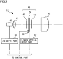
- FIG. 2 is a diagram showing a configuration example of a lamp unit.
- the lamp unit 34 in the illustrated example is configured to include a light source 40, a condensing lens 41, a liquid crystal panel 42, a pair of polarizers 43 and 44, and a projection lens 46.
- the liquid crystal element 45 is configured to include the liquid crystal panel 42 and the pair of polarizers 43 and 44.
- the light source 40 is configured to include LEDs (semiconductor light emitting elements) and is driven by the LED drive part 31 to emit light.
- the condensing lens 41 condenses the light emitted from the light source 40 and causes the light to enter the liquid crystal element 45.
- the liquid crystal element 45 is driven by the liquid crystal drive part 32 to form an image corresponding to various light distribution patterns by modulating incident light.
- the pair of polarizers 43 and 44 are disposed to face each other with the liquid crystal panel 42 interposed therebetween. There is no close contact between the pair of polarizers 43 and 44 and the liquid crystal panel 42, and a predetermined gap is provided therebetween.
- the pair of polarizers 43 and 44 are arranged such that their absorption axes are substantially orthogonal.
- a wire grid polarizer is preferably used, for example.
- the liquid crystal panel 42 a vertical alignment type liquid crystal panel is used. That is, the liquid crystal element 45 is configured as a normally black type liquid crystal element in which the light transmittance is extremely low (substantially a light-shielded state) when no voltage is applied.
- the projection lens 46 projects the image of the light formed by the liquid crystal element 45 toward front of the vehicle. Thereby, a light distribution pattern corresponding to the image of the light is formed in front of the vehicle.
- the headlight temperature sensor 33 is preferably installed in the vicinity of the liquid crystal panel 42 (for example, on the substrate surface). Thereby, the temperature of the liquid crystal panel 42 can be detected more reliably.
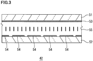
- FIG. 3 is a schematic cross-sectional view showing a configuration example of a liquid crystal panel.
- the illustrated liquid crystal panel 42 is configured to include a first substrate 51, a second substrate 52, a first electrode 53, a second electrode 54, and a liquid crystal layer 55.
- the first substrate 51 and the second substrate 52 are transparent substrates such as a glass substrate, a plastic substrate, etc., respectively. As illustrated, the first substrate 51 and the second substrate 52 are bonded together with a predetermined gap (for example, about 4 ⁇ m).
- the first electrode 53 is provided on one surface side of the first substrate 51.
- the second electrode 54 is provided on one surface side of the second substrate 52.
- the first electrode 53 and the second electrode 54 are each formed by appropriately patterning a transparent conductive film such as indium tin oxide (ITO).
- ITO indium tin oxide
- Each overlapping region of the first electrode 53 and the second electrode 54 becomes a pixel region (a light modulation region), and modulation can be applied individually to light incident to each of the pixel regions.
- an alignment film is provided on one surface of each of the first substrate 51 and the second substrate 52 so as to cover each electrode.
- the liquid crystal layer 55 is provided between the first substrate 51 and the second substrate 52.
- the liquid crystal layer 55 is configured to use a liquid crystal material having a negative dielectric anisotropy ⁇ .
- the refractive index anisotropy ⁇ n of the liquid crystal material is about 0.09, for example.
- the plurality of thick straight lines illustrated in the liquid crystal layer 55 area schematically indicates the alignment direction of liquid crystal molecules in the liquid crystal layer 55.
- the alignment direction of the liquid crystal molecules when no voltage is applied is vertically aligned, and is substantially perpendicular (for example, 89.9°, etc.) to the substrate surfaces of the first substrate 51 and the second substrate 52.
- the operation mode of the liquid crystal layer 55 is not limited to the exemplified vertical alignment mode, and various operation modes such as TN mode or IPS mode can be used.
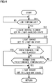
- FIG. 4 is a flowchart showing an operation procedure of the control part.
- an operation procedure is shown where the light emitted from the light source 40 of the lamp unit 34 is used to heat the liquid crystal element 45 to rapidly increase its temperature when the environmental temperature is extremely low after the start of the vehicle power unit.
- the processing sequence may be changed so long as no inconsistency occurs in the process, and is not limited to the illustrated processing sequence. Further, the start of the vehicle power unit is detected based on the operating state of the ignition switch, etc., for example.
- the heating control part 11 of the control part 1 determines whether or not the liquid crystal element 45 is estimated to be in a low temperature state meeting a certain standard (STEP S11). In the present embodiment, based on the temperatures detected by the plurality of headlight temperature sensors 33 of the respective headlights 6L and 6R, for example, when the temperature is -20° C. or lower, it is determined to be in a estimated low temperature state. Here, since two temperatures are detected by two of the headlight temperature sensors 33, the determination may be performed using any lower temperature, or the determination may be performed using an average value of the two temperatures, for example.
- the liquid crystal element 45 is estimated to be in a low temperature state meeting a certain standard may be determined based on the temperature detected by the cooling water temperature sensor 4 or the oil temperature sensor 5.
- the correlation between the temperature of the liquid crystal element 45 and the temperature of the cooling water and/or engine oil may be obtained in advance by experiments etc, and the temperature of the liquid crystal element 45 may be estimated based on the experiment data.
- STEP S11 If the temperature is not low (STEP S11; NO), the determination in STEP S11 is repeated at regular intervals. Therefore, even when the temperature of the lamp unit 34 drops for some reason after some time after starting the vehicle power unit, it is possible to start the heating operation of the liquid crystal element 45 at that point. In this case, it is preferable to initiate this operation when the vehicle is at a stop.
- the liquid crystal control part 12 instructed by the heating control part 11 of the control part 1 provides a signal to the liquid crystal drive part 32 in order to set the liquid crystal element 45 to a light-shielded state (STEP S12).
- the liquid crystal element 45 of the present embodiment is a normally black type, a control signal is provided to the liquid crystal drive part 32 so as to maintain the no voltage applied state.
- the liquid crystal element 45 is a normally white type
- a control signal is transmitted to perform such driving from the liquid crystal control part 12 of the control part 1 to the liquid crystal drive part 32.
- the light source control part 13 instructed by the heating control part 11 of the control part 1 transmits a control signal to the LED drive part 31 of the respective headlights 6L and 6R, thereby setting each light source 40 to a light-on state (STEP S13).
- a drive current greater than the rated current value may be applied to the LED of each light source 40, for example. Since it is a very short time to light the LED in such a condition and since the environmental temperature is extremely low, no damage is done to the LED.
- the plurality of liquid crystal elements 45 since the plurality of liquid crystal elements 45 is set to the light-shielded state, light hardly leaks from the respective headlights 6L and 6R to the outside. And the responsiveness of the plurality of liquid crystal elements 45 can be enhanced by heating the plurality of liquid crystal elements 45 using the light emitted from each light source 40 to raise its temperature. For example, when light from the light source 40 is absorbed by the pair of polarizers 43 and 44 and the temperature of each of the polarizer 43 and 44 rises, heat is transmitted to the liquid crystal panel 42 and the temperature of the liquid crystal panel 42 also rises. Thereby, heating of the panel can be performed.
- the heating control part 11 of the control part 1 determines whether or not a predetermined time has elapsed since each light source 40 was set to a light-on state (STEP S14).
- the predetermined time may be set to a constant value, or the predetermined time may be set in accordance with the level of temperature detected by the plurality of headlight temperature sensors 33 where the predetermined time becomes longer as the temperature becomes lower.
- the predetermined time is preferably set, for example, as the time required for the temperature of the liquid crystal element 45 to be higher than -20° C., and can be set for several tens of seconds to one minute. This is because the response time for briefly switching on high-beam is generally about 200 ms when -20° C. or higher although this depends on the conditions of the liquid crystal element 45 and the driving voltage, and it becomes possible to sufficiently cope with the light distribution control of high-beam flashing, etc.
- the heating control part 11 of the control part 1 determines whether or not the temperature of the liquid crystal element 45 has become equal to or higher than the predetermined temperature (STEP S15). If the temperature is not equal to or higher than the predetermined temperature (STEP S15; NO), the process returns to step S14. By carrying out this process, the lighting of the light source 40 is stopped in the event that the liquid crystal element 45 is sufficiently heated even when the predetermined time has not elapsed, thereby allowing to prevent the temperature of the liquid crystal element 45 from rising more than necessary.
- the light source control part 13 receiving the instruction from the heating control part 11 of the control part 1 transmits a control signal to the LED drive parts 31 of the respective headlights 6L and 6R, thereby setting each light source 40 to a light-off state (STEP S16).
- the light source control part 13 of the control part 1 cancels the light-off state and sets each light source 40 to a light-on state at a rated current value or less of the LED. Thereafter, the process returns to STEP S11.
- the light-on/light-off of the light source 40 may be determined based on the temperature without determining the elapsed time, and conversely, the light-on/light-off of the light source 40 may be determined based on the elapsed time without determining the temperature.
- FIG. 5 A configuration example of the lamp unit 34a in such a case is shown in FIG. 5 .
- metal particles for example, gold particles
- metal particles of nanometer size are added as a near infrared ray absorbing material to the liquid crystal layer of the liquid crystal panel 42a of the liquid crystal element 45.
- metal particles of nanometer size may be added to the film on the substrate such as the alignment film of the liquid crystal panel 42a or other protective film. Then, when heating is performed by the light source 40 as described above, a light source 35 also irradiates near infrared rays to the liquid crystal panel 42a.
- the near infrared rays (for example, a wavelength of about 3 ⁇ m or less) from the light source 35 directly irradiates the liquid crystal panel 42a without passing through the pair of polarizers 43 and 44.
- the near infrared rays are absorbed by the metal particles in the liquid crystal panel 42a, thereby enabling the temperature of the liquid crystal panel 42a to rise more efficiently.
- the light source 35 may be omitted.
- each of the projection lens 46, the polarizer 44 located on the projection lens 46 side, and the casing (outer lens etc.) of the lamp unit 34a has an infrared absorbing function.
- it allows to prevent an unintended heating of the liquid crystal panel 42a due to infrared rays such as sunlight incident from the outside.
Landscapes
- Physics & Mathematics (AREA)
- Chemical & Material Sciences (AREA)
- Crystallography & Structural Chemistry (AREA)
- Engineering & Computer Science (AREA)
- General Engineering & Computer Science (AREA)
- Nonlinear Science (AREA)
- General Physics & Mathematics (AREA)
- Optics & Photonics (AREA)
- Mathematical Physics (AREA)
- Lighting Device Outwards From Vehicle And Optical Signal (AREA)
- Mechanical Engineering (AREA)
Abstract
Description
- The present invention relates to a technique for controlling a vehicular lamp system that performs light distribution control using a liquid crystal element.
- Conventionally, a technique to control light distribution in which the shape and illuminance, etc. of light irradiated to the front of its own vehicle are controlled by using liquid crystal elements is known. (For example, refer to Japanese Unexamined Patent Application Publication No.
2005-183327 - Here, the environment in which the own vehicle is used varies, and sometimes the vehicle may be placed in a cryogenic environment (for example, minus several tens of degrees Celsius). Under such cryogenic environment, generally, the responsiveness of the liquid crystal elements decreases significantly.
- Thus, when normally black type liquid crystal elements are used for example, it may become difficult to irradiate high beam immediately after starting the vehicle power unit. For example, when the driver attempts to flash high-beams (briefly switch on high-beams), the liquid crystal elements may not respond in time, and inconvenience where high beam is hardly irradiated could occur.
- In a specific aspect, in a vehicular lamp system using a liquid crystal element, it is an object of the present invention to provide a technique capable of reliably performing light irradiation even in a cryogenic environment.
-
- [1] A control device for a vehicular lamp according to one aspect of the present invention is (a) a device adapted to control the operation of a vehicular lamp configured to include a light source and a liquid crystal element where (b) the liquid crystal element is set to a light-shielded state and the light source is set to a light-on state when the temperature of the liquid crystal element is estimated to be lower than a predetermined value, thereby heating the liquid crystal element by the light emitted from the light source.
- [2] A control device for a vehicular lamp according to one aspect of the present invention is (a) a device adapted to control the operation of a vehicular lamp configured to include a light source and a liquid crystal element which forms an image using light emitted from the light source including: (b) a heating control part adapted to control the heating of the liquid crystal element, (c) a liquid crystal operation control part adapted to control the operation of the liquid crystal element, (d) a light source operation control part adapted to control the operation of the light source (e) where the heating control part instructs the liquid crystal operation control part to set the liquid crystal element to a light-shielded state and instructs the liquid crystal operation control part to set the light source to a light-on state when the temperature of the liquid crystal element is estimated to be lower than a predetermined value.
- [3] A control method for a vehicular lamp according to one aspect of the present invention is (a) a method adapted to control the operation of a vehicular lamp configured to include a light source and a liquid crystal element where (b) the liquid crystal element is set to a light-shielded state and the light source is set to a light-on state when the temperature of the liquid crystal element is estimated to be lower than a predetermined value, thereby heating the liquid crystal element by the light emitted from the light source.
- [4] A vehicular lamp system according to one aspect of the present invention is a vehicular lamp system including the above-described control device and a vehicular lamp controlled by the control device.
- According to the above configurations, in a vehicular lamp system using a liquid crystal element, it is possible to reliably perform light irradiation even in a cryogenic environment.
-
-
FIG. 1 is a diagram showing an overall configuration of a vehicular lamp system according to one embodiment. -
FIG. 2 is a diagram showing a configuration example of a lamp unit. -
FIG. 3 is a schematic cross-sectional view showing a configuration example of a liquid crystal panel. -
FIG. 4 is a flowchart showing an operation procedure of the control part. -
FIG. 5 is a diagram showing a modified configuration example of the lamp unit. -
FIG. 1 is a diagram showing an overall configuration of a vehicular lamp system according to one embodiment. The illustrated vehicular lamp system is capable of performing selective light irradiation within the high beam irradiation range toward the front of the vehicle, and is configured to include a control part 1, animaging unit 2, alight switch 3, a cooling water temperature sensor 4 (abbreviated as COOLING WATER TEMP SENSOR inFIG. 1 ), an oil temperature sensor 5 (abbreviated as OIL TEMP SENSOR inFIG. 1 ), and a pair ofheadlights - The control part 1 controls the whole operation of the vehicular lamp system. The control part 1 carries out a predetermined operation program in a computer system comprising a CPU, ROM, RAM, etc, for example. As functional blocks realized by executing the operation program, the control part 1 is configured to include a
heating control part 11 which is adapted to control heating of the liquid crystal element included in eachheadlight crystal control part 12 which is adapted to control the operation of the liquid crystal element, a lightsource control part 13 which is adapted to control the operation of the light source included in eachheadlight FIG. 1 ) which is adapted to set a light distribution pattern when selective light irradiation is performed within the high beam irradiation range. - The
imaging unit 2 is configured to include acamera 21 and animage processing part 22. Thecamera 21 is installed at a predetermined position of the vehicle (for example, upper portion inside the windshield), and captures the space in front of the vehicle to generate an image. Theimage processing part 22 is adapted to perform a predetermined image recognition process on the image generated by thecamera 21 to detect a preceding vehicle, an oncoming vehicle, a pedestrian, a traffic lane, etc. existing in front of the vehicle. A light distribution pattern is established by the lightdistribution setting part 14 described above in accordance with the detected preceding vehicle, oncoming vehicle, etc., and the operation of a liquidcrystal drive part 32 is controlled by the liquidcrystal control part 12 so as to form an image according to the light distribution pattern. Here, note that some or all of the functions of theimage processing part 22 may be realized in the control part 1. - The
light switch 3 is provided near the driver's seat of the vehicle, and is used by the driver to switch on or switch off the headlights and/or to briefly switch on high-beam (flash high-beam). - The cooling
water temperature sensor 4 detects the cooling water temperature of the vehicle. Theoil temperature sensor 5 detects the engine oil temperature of the vehicle. Here, since each of these sensors is usually already provided in the vehicle, they can be utilized. - The pair of
headlights headlights LED drive part 31, a liquidcrystal drive part 32, a headlight temperature sensor 33 (abbreviated as HEADLIGHT TEMP SENSOR inFIG. 1 ), and alamp unit 34. - The
LED drive part 31 drives the LED included in the light source provided in thelamp unit 34 based on the control signal provided from the lightsource control part 13. The liquidcrystal drive part 32 drives the liquid crystal element provided in thelamp unit 34 based on the control signal provided from the liquidcrystal control part 12. - Here, in the present embodiment, a "liquid crystal operation control part" is configured to include the liquid
crystal control part 12 of the control part 1 and the plurality of liquidcrystal drive parts 32 of therespective headlights source control part 13 of the control part 1 and the plurality ofLED drive parts 31 of therespective headlights - Each
headlight temperature sensor 33 is installed at an appropriate position within the housing of therespective headlights respective headlights 6L and 6, more preferably, the sensor detects the temperature near thelamp unit 34. - The
lamp unit 34 is driven by each of theLED drive part 31 and the liquidcrystal drive part 32 to emit light in front of the vehicle according to various light distribution patterns. -
FIG. 2 is a diagram showing a configuration example of a lamp unit. Thelamp unit 34 in the illustrated example is configured to include alight source 40, acondensing lens 41, aliquid crystal panel 42, a pair ofpolarizers projection lens 46. Here, theliquid crystal element 45 is configured to include theliquid crystal panel 42 and the pair ofpolarizers - The
light source 40 is configured to include LEDs (semiconductor light emitting elements) and is driven by theLED drive part 31 to emit light. Thecondensing lens 41 condenses the light emitted from thelight source 40 and causes the light to enter theliquid crystal element 45. - The
liquid crystal element 45 is driven by the liquidcrystal drive part 32 to form an image corresponding to various light distribution patterns by modulating incident light. In thisliquid crystal element 45, the pair ofpolarizers liquid crystal panel 42 interposed therebetween. There is no close contact between the pair ofpolarizers liquid crystal panel 42, and a predetermined gap is provided therebetween. In the present embodiment, the pair ofpolarizers polarizers - Further, as the
liquid crystal panel 42, a vertical alignment type liquid crystal panel is used. That is, theliquid crystal element 45 is configured as a normally black type liquid crystal element in which the light transmittance is extremely low (substantially a light-shielded state) when no voltage is applied. - The
projection lens 46 projects the image of the light formed by theliquid crystal element 45 toward front of the vehicle. Thereby, a light distribution pattern corresponding to the image of the light is formed in front of the vehicle. - Here, as shown in
FIG. 2 , theheadlight temperature sensor 33 is preferably installed in the vicinity of the liquid crystal panel 42 (for example, on the substrate surface). Thereby, the temperature of theliquid crystal panel 42 can be detected more reliably. -
FIG. 3 is a schematic cross-sectional view showing a configuration example of a liquid crystal panel. The illustratedliquid crystal panel 42 is configured to include afirst substrate 51, asecond substrate 52, afirst electrode 53, asecond electrode 54, and aliquid crystal layer 55. - The
first substrate 51 and thesecond substrate 52 are transparent substrates such as a glass substrate, a plastic substrate, etc., respectively. As illustrated, thefirst substrate 51 and thesecond substrate 52 are bonded together with a predetermined gap (for example, about 4 µm). - The
first electrode 53 is provided on one surface side of thefirst substrate 51. Similarly, thesecond electrode 54 is provided on one surface side of thesecond substrate 52. Thefirst electrode 53 and thesecond electrode 54 are each formed by appropriately patterning a transparent conductive film such as indium tin oxide (ITO). Each overlapping region of thefirst electrode 53 and thesecond electrode 54 becomes a pixel region (a light modulation region), and modulation can be applied individually to light incident to each of the pixel regions. - Here, although not shown, an alignment film is provided on one surface of each of the
first substrate 51 and thesecond substrate 52 so as to cover each electrode. - The
liquid crystal layer 55 is provided between thefirst substrate 51 and thesecond substrate 52. In the present embodiment, theliquid crystal layer 55 is configured to use a liquid crystal material having a negative dielectric anisotropy Δε. The refractive index anisotropy Δn of the liquid crystal material is about 0.09, for example. The plurality of thick straight lines illustrated in theliquid crystal layer 55 area schematically indicates the alignment direction of liquid crystal molecules in theliquid crystal layer 55. In theliquid crystal layer 55 of this embodiment, the alignment direction of the liquid crystal molecules when no voltage is applied is vertically aligned, and is substantially perpendicular (for example, 89.9°, etc.) to the substrate surfaces of thefirst substrate 51 and thesecond substrate 52. Here, the operation mode of theliquid crystal layer 55 is not limited to the exemplified vertical alignment mode, and various operation modes such as TN mode or IPS mode can be used. -
FIG. 4 is a flowchart showing an operation procedure of the control part. Here, an operation procedure is shown where the light emitted from thelight source 40 of thelamp unit 34 is used to heat theliquid crystal element 45 to rapidly increase its temperature when the environmental temperature is extremely low after the start of the vehicle power unit. Here, the processing sequence may be changed so long as no inconsistency occurs in the process, and is not limited to the illustrated processing sequence. Further, the start of the vehicle power unit is detected based on the operating state of the ignition switch, etc., for example. - The
heating control part 11 of the control part 1 determines whether or not theliquid crystal element 45 is estimated to be in a low temperature state meeting a certain standard (STEP S11). In the present embodiment, based on the temperatures detected by the plurality ofheadlight temperature sensors 33 of therespective headlights headlight temperature sensors 33, the determination may be performed using any lower temperature, or the determination may be performed using an average value of the two temperatures, for example. - Furthermore, whether or not the
liquid crystal element 45 is estimated to be in a low temperature state meeting a certain standard may be determined based on the temperature detected by the coolingwater temperature sensor 4 or theoil temperature sensor 5. In this case, the correlation between the temperature of theliquid crystal element 45 and the temperature of the cooling water and/or engine oil may be obtained in advance by experiments etc, and the temperature of theliquid crystal element 45 may be estimated based on the experiment data. - If the temperature is not low (STEP S11; NO), the determination in STEP S11 is repeated at regular intervals. Therefore, even when the temperature of the
lamp unit 34 drops for some reason after some time after starting the vehicle power unit, it is possible to start the heating operation of theliquid crystal element 45 at that point. In this case, it is preferable to initiate this operation when the vehicle is at a stop. - If the temperature is low (STEP S11; YES), the liquid
crystal control part 12 instructed by theheating control part 11 of the control part 1 provides a signal to the liquidcrystal drive part 32 in order to set theliquid crystal element 45 to a light-shielded state (STEP S12). Here, since theliquid crystal element 45 of the present embodiment is a normally black type, a control signal is provided to the liquidcrystal drive part 32 so as to maintain the no voltage applied state. - Here, in the case where the
liquid crystal element 45 is a normally white type, since theliquid crystal element 45 needs to be in a light-shielded state, a control signal is transmitted to perform such driving from the liquidcrystal control part 12 of the control part 1 to the liquidcrystal drive part 32. - Next, the light
source control part 13 instructed by theheating control part 11 of the control part 1 transmits a control signal to theLED drive part 31 of therespective headlights light source 40 to a light-on state (STEP S13). Here, a drive current greater than the rated current value may be applied to the LED of eachlight source 40, for example. Since it is a very short time to light the LED in such a condition and since the environmental temperature is extremely low, no damage is done to the LED. - At this time, since the plurality of
liquid crystal elements 45 is set to the light-shielded state, light hardly leaks from therespective headlights liquid crystal elements 45 can be enhanced by heating the plurality ofliquid crystal elements 45 using the light emitted from eachlight source 40 to raise its temperature. For example, when light from thelight source 40 is absorbed by the pair ofpolarizers polarizer liquid crystal panel 42 and the temperature of theliquid crystal panel 42 also rises. Thereby, heating of the panel can be performed. - The
heating control part 11 of the control part 1 determines whether or not a predetermined time has elapsed since eachlight source 40 was set to a light-on state (STEP S14). Here, the predetermined time may be set to a constant value, or the predetermined time may be set in accordance with the level of temperature detected by the plurality ofheadlight temperature sensors 33 where the predetermined time becomes longer as the temperature becomes lower. - The predetermined time is preferably set, for example, as the time required for the temperature of the
liquid crystal element 45 to be higher than -20° C., and can be set for several tens of seconds to one minute. This is because the response time for briefly switching on high-beam is generally about 200 ms when -20° C. or higher although this depends on the conditions of theliquid crystal element 45 and the driving voltage, and it becomes possible to sufficiently cope with the light distribution control of high-beam flashing, etc. - If the predetermined time has not elapsed (STEP S14; NO), the
heating control part 11 of the control part 1 determines whether or not the temperature of theliquid crystal element 45 has become equal to or higher than the predetermined temperature (STEP S15). If the temperature is not equal to or higher than the predetermined temperature (STEP S15; NO), the process returns to step S14. By carrying out this process, the lighting of thelight source 40 is stopped in the event that theliquid crystal element 45 is sufficiently heated even when the predetermined time has not elapsed, thereby allowing to prevent the temperature of theliquid crystal element 45 from rising more than necessary. - If the predetermined time has elapsed (STEP S14; YES), or if the temperature of the
liquid crystal element 45 has become equal to or higher than the predetermined temperature (STEP S15; YES), then the lightsource control part 13 receiving the instruction from theheating control part 11 of the control part 1 transmits a control signal to theLED drive parts 31 of therespective headlights light source 40 to a light-off state (STEP S16). Here, when thelight switch 3 is operated and irradiation of high beam is instructed, the lightsource control part 13 of the control part 1 cancels the light-off state and sets eachlight source 40 to a light-on state at a rated current value or less of the LED. Thereafter, the process returns to STEP S11. - According to the embodiment as described above, in a vehicular lamp system using a liquid crystal element, in a cryogenic environment, since the
liquid crystal element 45 is rapidly heated to improve the responsiveness by using light from thelight source 40, it is possible to reliably perform light irradiation even in such cryogenic environment. - It should be noted that this invention is not limited to the subject matter of the foregoing embodiments, and can be implemented by being variously modified within the scope of the present invention as defined by the appended claims. For example, in the above-described embodiment, when the
light source 40 is set to lighting-on state in order to heat theliquid crystal element 45, the light-on state of thelight source 40 is halted either when the predetermined time has elapsed or when theliquid crystal element 45 temperature has become equal to or higher than the predetermined value, but only one of the determinations may be applied. That is, the light-on/light-off of thelight source 40 may be determined based on the temperature without determining the elapsed time, and conversely, the light-on/light-off of thelight source 40 may be determined based on the elapsed time without determining the temperature. - Further, it is also preferable to increase the heating efficiency of the liquid crystal element by adding nanoparticles to the liquid crystal element. A configuration example of the
lamp unit 34a in such a case is shown inFIG. 5 . For example, metal particles (for example, gold particles) of nanometer size are added as a near infrared ray absorbing material to the liquid crystal layer of theliquid crystal panel 42a of theliquid crystal element 45. Alternatively, metal particles of nanometer size may be added to the film on the substrate such as the alignment film of theliquid crystal panel 42a or other protective film. Then, when heating is performed by thelight source 40 as described above, alight source 35 also irradiates near infrared rays to theliquid crystal panel 42a. As illustrated, it is preferable that the near infrared rays (for example, a wavelength of about 3 µm or less) from thelight source 35 directly irradiates theliquid crystal panel 42a without passing through the pair ofpolarizers liquid crystal panel 42a, thereby enabling the temperature of theliquid crystal panel 42a to rise more efficiently. Here, when near infrared rays are sufficiently emitted along with visible light from thelight source 40, thelight source 35 may be omitted. - When adopting the configuration of
FIG. 5 , it is preferable that each of theprojection lens 46, thepolarizer 44 located on theprojection lens 46 side, and the casing (outer lens etc.) of thelamp unit 34a (not shown in the figure) has an infrared absorbing function. Thus, it allows to prevent an unintended heating of theliquid crystal panel 42a due to infrared rays such as sunlight incident from the outside.
Claims (9)
- A control device for a vehicular lamp adapted to control the operation of a vehicular lamp configured to include a light source and a liquid crystal element:
wherein the liquid crystal element is set to a light-shielded state and the light source is set to a light-on state when the temperature of the liquid crystal element is estimated to be lower than a predetermined value, thereby heating the liquid crystal element by the light emitted from the light source. - The control device for a vehicular lamp according to claim 1:
wherein a drive current greater than rated current value is applied to the light source when setting the light source to the light-on state. - The control device for a vehicular lamp according to claim 1 or 2:
wherein the light-on state of the light source is maintained until the lapse of time which is variably set according to the temperature of the liquid crystal element when the liquid crystal element is estimated to be lower than the predetermined value. - The control device for a vehicular lamp according to claim 1 or 2:
wherein the light-on state of the light source is maintained until the temperature of the liquid crystal element reaches or exceeds the predetermined value. - The control device for a vehicular lamp according to any one of claims 1 to 4:
wherein the temperature of the liquid crystal element is estimated based on the temperature detected at or in the vicinity of the surface of the liquid crystal element. - The control device for a vehicular lamp according to any one of claims 1 to 4:
wherein the temperature of the liquid crystal element is estimated based on the cooling water temperature or the engine oil temperature of the vehicle in which the vehicular lamp is installed. - A control device for a vehicular lamp adapted to control the operation of a vehicular lamp configured to include a light source and a liquid crystal element which forms an image using light emitted from the light source comprising:a heating control part adapted to control the heating of the liquid crystal element,a liquid crystal operation control part adapted to control the operation of the liquid crystal element, anda light source operation control part adapted to control the operation of the light source;wherein the heating control part instructs the liquid crystal operation control part to set the liquid crystal element to a light-shielded state and instructs the liquid crystal operation control part to set the light source to a light-on state when the temperature of the liquid crystal element is estimated to be lower than a predetermined value.
- A control method for a vehicular lamp adapted to control the operation of a vehicular lamp configured to include a light source and a liquid crystal element:
wherein the liquid crystal element is set to a light-shielded state and the light source is set to a light-on state when the temperature of the liquid crystal element is estimated to be lower than a predetermined value, thereby heating the liquid crystal element by the light emitted from the light source. - A vehicular lamp system comprising:the control device according to any one of claims 1 to 7; anda vehicular lamp controlled by the control device.
Applications Claiming Priority (1)
| Application Number | Priority Date | Filing Date | Title |
|---|---|---|---|
| JP2018155740A JP7193270B2 (en) | 2018-08-22 | 2018-08-22 | Vehicle lighting control device, vehicle lighting control method, vehicle lighting system |
Publications (1)
| Publication Number | Publication Date |
|---|---|
| EP3614043A1 true EP3614043A1 (en) | 2020-02-26 |
Family
ID=67587394
Family Applications (1)
| Application Number | Title | Priority Date | Filing Date |
|---|---|---|---|
| EP19190553.8A Withdrawn EP3614043A1 (en) | 2018-08-22 | 2019-08-07 | Control device for vehicular lamp, control method for vehicular lamp, vehicular lamp system |
Country Status (3)
| Country | Link |
|---|---|
| US (1) | US11009734B2 (en) |
| EP (1) | EP3614043A1 (en) |
| JP (1) | JP7193270B2 (en) |
Cited By (1)
| Publication number | Priority date | Publication date | Assignee | Title |
|---|---|---|---|---|
| GB2637535A (en) * | 2024-01-26 | 2025-07-30 | Envisics Ltd | Thin shutter stack |
Families Citing this family (2)
| Publication number | Priority date | Publication date | Assignee | Title |
|---|---|---|---|---|
| EP4032751A4 (en) * | 2019-09-19 | 2022-10-26 | Koito Manufacturing Co., Ltd. | INFRARED LIGHTING UNIT SYSTEM FOR VEHICLE, INFRARED SENSOR SYSTEM FOR VEHICLE, AND LIGHTING UNIT WITH BUILT-IN INFRARED SENSOR AND LIGHTING UNIT WITH BUILT-IN OPTICAL SENSOR FOR VEHICLE |
| DE102022125753A1 (en) | 2022-10-06 | 2024-04-11 | Marelli Automotive Lighting Reutlingen (Germany) GmbH | Device and method for temperature stabilization of a matrix headlight |
Citations (7)
| Publication number | Priority date | Publication date | Assignee | Title |
|---|---|---|---|---|
| EP1372022A2 (en) * | 2002-06-12 | 2003-12-17 | Sharp Kabushiki Kaisha | Liquid crystal display device |
| JP2005183327A (en) | 2003-12-24 | 2005-07-07 | Stanley Electric Co Ltd | Vehicle headlamp |
| KR20060017205A (en) * | 2004-08-20 | 2006-02-23 | 삼성에스디아이 주식회사 | LCD and its driving method |
| US20060164230A1 (en) * | 2000-03-02 | 2006-07-27 | Dewind Darryl P | Interior mirror assembly with display |
| DE102008008664A1 (en) * | 2008-02-12 | 2009-09-10 | Continental Automotive Gmbh | Vehicle headlight for motor vehicles, particularly passenger car, comprises illuminant and cover disk arranged at its front side, and illuminant is positioned in area of cover disk and emits light in direction of rear side of headlight |
| WO2014002630A1 (en) * | 2012-06-29 | 2014-01-03 | 株式会社小糸製作所 | Vehicle lamp and control method therefor |
| DE112014003540T5 (en) * | 2013-08-01 | 2016-05-04 | Denso Corporation | Head-up display device |
Family Cites Families (9)
| Publication number | Priority date | Publication date | Assignee | Title |
|---|---|---|---|---|
| JP3514946B2 (en) * | 1997-05-29 | 2004-04-05 | 日産自動車株式会社 | Liquid crystal display |
| JP4942037B2 (en) | 2007-06-06 | 2012-05-30 | スタンレー電気株式会社 | Liquid crystal display |
| JP5844074B2 (en) | 2011-06-16 | 2016-01-13 | 株式会社小糸製作所 | Vehicle headlight control device |
| JP5812444B2 (en) | 2012-04-13 | 2015-11-11 | 日東電工株式会社 | Optical member, polarizing plate set and liquid crystal display device |
| JP2014002235A (en) * | 2012-06-18 | 2014-01-09 | Stanley Electric Co Ltd | Three-dimensional image display device and illumination device |
| JP6202384B2 (en) | 2013-09-13 | 2017-09-27 | 日本精機株式会社 | Laser light source control device and vehicle display device |
| JP2015127756A (en) * | 2013-12-27 | 2015-07-09 | 本田技研工業株式会社 | Liquid crystal display |
| WO2015193996A1 (en) * | 2014-06-18 | 2015-12-23 | 日立マクセル株式会社 | Headlight device, and vehicle device using same |
| KR101859047B1 (en) | 2015-06-24 | 2018-05-17 | 엘지전자 주식회사 | Headlamp, Adaptive Driver Assistance System and Vehicle |
-
2018
- 2018-08-22 JP JP2018155740A patent/JP7193270B2/en active Active
-
2019
- 2019-08-07 EP EP19190553.8A patent/EP3614043A1/en not_active Withdrawn
- 2019-08-22 US US16/547,771 patent/US11009734B2/en active Active
Patent Citations (7)
| Publication number | Priority date | Publication date | Assignee | Title |
|---|---|---|---|---|
| US20060164230A1 (en) * | 2000-03-02 | 2006-07-27 | Dewind Darryl P | Interior mirror assembly with display |
| EP1372022A2 (en) * | 2002-06-12 | 2003-12-17 | Sharp Kabushiki Kaisha | Liquid crystal display device |
| JP2005183327A (en) | 2003-12-24 | 2005-07-07 | Stanley Electric Co Ltd | Vehicle headlamp |
| KR20060017205A (en) * | 2004-08-20 | 2006-02-23 | 삼성에스디아이 주식회사 | LCD and its driving method |
| DE102008008664A1 (en) * | 2008-02-12 | 2009-09-10 | Continental Automotive Gmbh | Vehicle headlight for motor vehicles, particularly passenger car, comprises illuminant and cover disk arranged at its front side, and illuminant is positioned in area of cover disk and emits light in direction of rear side of headlight |
| WO2014002630A1 (en) * | 2012-06-29 | 2014-01-03 | 株式会社小糸製作所 | Vehicle lamp and control method therefor |
| DE112014003540T5 (en) * | 2013-08-01 | 2016-05-04 | Denso Corporation | Head-up display device |
Cited By (2)
| Publication number | Priority date | Publication date | Assignee | Title |
|---|---|---|---|---|
| GB2637535A (en) * | 2024-01-26 | 2025-07-30 | Envisics Ltd | Thin shutter stack |
| WO2025157909A1 (en) * | 2024-01-26 | 2025-07-31 | Envisics Ltd | Thin shutter stack |
Also Published As
| Publication number | Publication date |
|---|---|
| US20200063940A1 (en) | 2020-02-27 |
| JP2020029166A (en) | 2020-02-27 |
| US11009734B2 (en) | 2021-05-18 |
| JP7193270B2 (en) | 2022-12-20 |
Similar Documents
| Publication | Publication Date | Title |
|---|---|---|
| US11009734B2 (en) | Control device for vehicular lamp, control method for vehicular lamp, vehicular lamp system | |
| JP6166225B2 (en) | Vehicle headlamp control device | |
| WO2022153754A1 (en) | Headlight control device, headlight control method, and headlight system | |
| US10551018B2 (en) | Vehicular lamp, vehicular lamp system | |
| JP7234020B2 (en) | lighting units, lighting systems | |
| JP6959852B2 (en) | Lighting device | |
| KR102288915B1 (en) | Predictive control system for intelligent head lamp and method thereof | |
| WO2018225655A1 (en) | Vehicular headlamp system | |
| US10788185B2 (en) | Vehicular lamp system configured to change the extent of high-low ratio of the illumination distributions | |
| EP3447368B1 (en) | Vehicle headlamp system | |
| KR20110084785A (en) | Headlamp | |
| KR20160112429A (en) | Lamp for vehicle | |
| EP3992704B1 (en) | Liquid crystal element and illumination device | |
| JP2019102380A (en) | Vehicular lighting fixture system | |
| JP6846294B2 (en) | Vehicle headlight system | |
| JP7219085B2 (en) | Lamp units, vehicle lighting systems | |
| CN209534879U (en) | High beam conversion device and automobile | |
| CN110764303A (en) | An anti-glare car headlight structure based on infrared camera | |
| KR101316188B1 (en) | Apparatus and method for controlling smart glass of vehicle | |
| JP2019140031A (en) | Lighting appliance system for vehicle | |
| JP7001370B2 (en) | Vehicle headlight system and its control method | |
| JPH0716244Y2 (en) | Vehicle headlight device | |
| US12560297B2 (en) | Lighting apparatus, vehicle headlight system | |
| CN115291428B (en) | Light processing device, automobile and control method of light processing device | |
| CN114484370A (en) | Laser-assisted high beam lighting module control system |
Legal Events
| Date | Code | Title | Description |
|---|---|---|---|
| PUAI | Public reference made under article 153(3) epc to a published international application that has entered the european phase |
Free format text: ORIGINAL CODE: 0009012 |
|
| AK | Designated contracting states |
Kind code of ref document: A1 Designated state(s): AL AT BE BG CH CY CZ DE DK EE ES FI FR GB GR HR HU IE IS IT LI LT LU LV MC MK MT NL NO PL PT RO RS SE SI SK SM TR |
|
| AX | Request for extension of the european patent |
Extension state: BA ME |
|
| 17P | Request for examination filed |
Effective date: 20200818 |
|
| RBV | Designated contracting states (corrected) |
Designated state(s): AL AT BE BG CH CY CZ DE DK EE ES FI FR GB GR HR HU IE IS IT LI LT LU LV MC MK MT NL NO PL PT RO RS SE SI SK SM TR |
|
| STAA | Information on the status of an ep patent application or granted ep patent |
Free format text: STATUS: THE APPLICATION HAS BEEN WITHDRAWN |
|
| 18W | Application withdrawn |
Effective date: 20201023 |