EP3614019A1 - Wave gear device - Google Patents
Wave gear device Download PDFInfo
- Publication number
- EP3614019A1 EP3614019A1 EP17913875.5A EP17913875A EP3614019A1 EP 3614019 A1 EP3614019 A1 EP 3614019A1 EP 17913875 A EP17913875 A EP 17913875A EP 3614019 A1 EP3614019 A1 EP 3614019A1
- Authority
- EP
- European Patent Office
- Prior art keywords
- gear
- wave generator
- rigid
- toothed gear
- pressing members
- Prior art date
- Legal status (The legal status is an assumption and is not a legal conclusion. Google has not performed a legal analysis and makes no representation as to the accuracy of the status listed.)
- Granted
Links
Images


Classifications
-
- F—MECHANICAL ENGINEERING; LIGHTING; HEATING; WEAPONS; BLASTING
- F16—ENGINEERING ELEMENTS AND UNITS; GENERAL MEASURES FOR PRODUCING AND MAINTAINING EFFECTIVE FUNCTIONING OF MACHINES OR INSTALLATIONS; THERMAL INSULATION IN GENERAL
- F16H—GEARING
- F16H49/00—Other gearings
- F16H49/001—Wave gearings, e.g. harmonic drive transmissions
-
- F—MECHANICAL ENGINEERING; LIGHTING; HEATING; WEAPONS; BLASTING
- F16—ENGINEERING ELEMENTS AND UNITS; GENERAL MEASURES FOR PRODUCING AND MAINTAINING EFFECTIVE FUNCTIONING OF MACHINES OR INSTALLATIONS; THERMAL INSULATION IN GENERAL
- F16C—SHAFTS; FLEXIBLE SHAFTS; ELEMENTS OR CRANKSHAFT MECHANISMS; ROTARY BODIES OTHER THAN GEARING ELEMENTS; BEARINGS
- F16C33/00—Parts of bearings; Special methods for making bearings or parts thereof
- F16C33/30—Parts of ball or roller bearings
-
- F—MECHANICAL ENGINEERING; LIGHTING; HEATING; WEAPONS; BLASTING
- F16—ENGINEERING ELEMENTS AND UNITS; GENERAL MEASURES FOR PRODUCING AND MAINTAINING EFFECTIVE FUNCTIONING OF MACHINES OR INSTALLATIONS; THERMAL INSULATION IN GENERAL
- F16H—GEARING
- F16H1/00—Toothed gearings for conveying rotary motion
- F16H1/28—Toothed gearings for conveying rotary motion with gears having orbital motion
- F16H1/32—Toothed gearings for conveying rotary motion with gears having orbital motion in which the central axis of the gearing lies inside the periphery of an orbital gear
-
- F—MECHANICAL ENGINEERING; LIGHTING; HEATING; WEAPONS; BLASTING
- F16—ENGINEERING ELEMENTS AND UNITS; GENERAL MEASURES FOR PRODUCING AND MAINTAINING EFFECTIVE FUNCTIONING OF MACHINES OR INSTALLATIONS; THERMAL INSULATION IN GENERAL
- F16H—GEARING
- F16H57/00—General details of gearing
- F16H57/0006—Vibration-damping or noise reducing means specially adapted for gearings
Definitions
- the present invention relates to a strain wave gearing, and, in particular, to a strain wave gearing which can reduce rotational torque of a wave generator for generating a wave motion in a flexible gear.
- a strain wave gearing is generally configured so that a wave generator causes to generate a wave motion in a flexible externally toothed gear disposed inside a rigid internally toothed gear and relative rotation is generated between the gears in accordance with the difference in the number of teeth therebetween.
- a rolling-contact type wave generator is employed as a wave generator.
- a contact-rolling type wave generator is provided with a rotating body called as a plug or a cam plate having an elliptical contour, the rotating body being mounted inside the externally toothed gear via a rolling bearing.
- the externally toothed gear is flexed elliptically along the elliptical contour of the rotating body and is meshed with the internally toothed gear. When the rotating body is rotated by a motor or the like, meshing portions of the gears are moved in the circumferential direction. (Wave motion is generated in the externally toothed gear.)
- a sliding-contact type wave generator is also proposed for the purpose of obtaining high efficiency, etc. during high-speed rotation.
- Patent documents 1 and 2 propose strain wave gearings provided with a sliding-contact type wave generator.
- a sliding-contact type wave generator has a rotating body, for example, a plug that is made to directly come in contact with the inner peripheral surface of an externally toothed gear and is made to slide along the inner peripheral surface thereof, whereby generating wave motion in the externally toothed gear.
- the sliding-contact type wave generator has an advantage that viscous resistance in rotation is small and an input torque hardly changes even if input rotational speed is changed, but has a disadvantage that a rotational torque to generate the wave motion is large.
- An object of the present invention is to provide a strain wave gearing configured to be capable of reducing rotational torque of a wave generator.
- a strain wave gearing of the present invention has a rigid gear, a flexible gear and a wave generator.
- the flexible gear is arranged coaxially with the rigid gear and is relatively rotatable with respect to the rigid gear about a center axis line of the rigid gear.
- the wave generator is arranged coaxially with the flexible gear and is relatively rotatable with respect to the flexible gear about the center axis line.
- the wave generator is provided with: a plurality of gear pressing units to flex the flexible gear in a radial direction at positions at equal angular intervals in a circumferential direction so as to form a plurality of meshing portions where the flexible gear meshes with the rigid gear; and an excitation unit to cause the gear pressing units to generate ultrasonic vibration in the radial direction.
- the respective gear pressing units of the wave generator press the flexible gear in the radial direction to flex in a state in which the pressing units are applied with ultrasonic vibration.
- ultrasonic vibration of 20kHz to 80kHz is applied to the sliding-contact parts between the gear pressing unit and the flexible gear.
- the apparent frictional coefficient at the contact surface of each sliding-contact part can be greatly reduced.
- the ultrasonic vibration is transmitted to a meshing portion between the flexible gear and the rigid gear, and the apparent frictional coefficient at the meshing tooth surface can be greatly reduced. Accordingly, rotational torque of the wave generator can be reduced.
- the wave generator is provided with a rotating body called as a plug or a cam plate having the center axis line as a rotational center.
- gear pressing units it is possible, as the gear pressing units, to use gear pressing members that are attached, in a radially slidable state, to the rotating body at positions at equal angular intervals in the circumferential direction.
- the excitation unit one or more piezoelectric elements can be used, the piezoelectric elements being attached to the rotating body and being able to displace in one axial direction.
- the piezoelectric elements are linked to the gear pressing members in a state in which the direction of the displacement thereof coincides with the radial direction.
- strain wave gearing is provided with a rigid internally toothed gear, a flexible externally toothed gear, and a wave generator to flex the externally toothed gear into an elliptical shape and mesh with the internally toothed gear at two locations on both ends of the major axis of the elliptical shape.
- the wave generator has a rigid plug as the rotating body, the plug having an elliptical outer peripheral surface and being mounted in the externally toothed gear.
- the plug can be constituted by: a plug body member forming a main portion of the plug excluding end portions located on both sides of the elliptical shape in the major-axis direction; two gear pressing members that respectively form the end portions on the both sides in the major-axis direction; and one or a plurality of piezoelectric elements.
- Each of the gear pressing members is attached to the plug body member in a slidable state in the major-axis direction.
- the piezoelectric elements are attached to the plug body member at positions between the gear pressing members so that the direction of the displacement thereof is in line with the major-axis direction.
- the gear pressing members may be assembled to the plug body member so as to form a state in which the reaction force from the elliptically flexed externally toothed gear is applied to the piezoelectric members as a preliminary load.
- the elliptical rigid plug is provided on the both ends in the major-axis direction with the gear pressing members, a circumferential length of the outer peripheral surface of which can be such that it extends across an angle of 30 degrees to 40 degrees left and right from the major axis, preferably 35 degrees.
- a large radial load is applied to the area within an angular range of approximately 35 degrees left and right from the major axis.
- the ultrasonic vibration in the major-axis direction can be applied to the area where the radial load is large, whereby the rotational torque of the wave generator can be effectively reduced.
- the plug body member that supports the gear pressing members in a slidable manner it is possible to provide sufficient guide parts to guide the gear pressing members in the major-axis direction in a reliable manner.
- a wave generator which flexes a flexible externally toothed gear into an elliptical shape to mesh partially with a rigid internally toothed gear, is provided with a rotating body (which is a plug or a cam plate) and a rolling bearing mounted between an inner peripheral surface of the externally toothed gear and an elliptical outer peripheral surface of the rotating body.
- Embodiments of a strain wave gearing according to the present invention will be described with reference to the drawings.
- the following embodiments relate to a cup-type strain wave gearing.
- the present invention can also be applied to a silk-hat type strain wave gearing and a flat-type strain wave gearing in a similar manner.
- FIG. 1(a) is a schematic longitudinal cross-sectional view of a strain wave gearing according to an embodiment of the present invention
- FIG. 1(b) is a schematic end view thereof.
- a strain wave gearing 1 is provided with an annular rigid internally toothed gear 2 (rigid gear), a cup-shaped flexible externally toothed gear 3 (flexible gear) disposed coaxially inside the internally toothed gear, and a wave generator 4 fitted coaxially into the externally toothed gear.
- the internally toothed gear 2 and the externally toothed gear 3 are supported by a not-shown support member in a relatively rotatable state about a device center axis line 1a.
- the externally toothed gear 3 has a cylindrical body and external teeth 3a formed on the cylindrical body, and the wave generator 4 is fitted into the inner peripheral surface 3b of the cylindrical body where the external teeth are formed.
- the externally toothed gear 3 and the wave generator 4 are also relatively rotatable about the device center axis line 1a.
- the wave generator 4 makes the externally toothed gear 3 to flex into a shape along an elliptical shape and mesh with the internally toothed gear 2 at positions on both ends of a major axis Lmax of the elliptical shape.
- two meshing portions 5a and 5b of the externally toothed gear 3 with the internally toothed gear 2 are moved in the circumferential direction of the internally toothed gear 2. This causes relative rotation to occur between the two gears 2 and 3 in accordance with the difference in the number of teeth between the two gears 2 and 3.
- the wave generator 4 has a rigid plug 6 (rotating body) provided with an elliptical outer peripheral surface.
- the plug 6 is constituted by: a plug body member 7 forming a plug main portion excluding plug end portions located on both sides in the direction of the major axis Lmax; and two gear pressing members 8 forming the plug end portions on the both sides in the direction of the major axis Lmax.
- the plug 6 is also provided with two piezoelectric elements 9 (excitation units) to generate ultrasonic vibration along the direction of the major axis Lmax in the gear pressing members 8. Power supply lines 10a and 10b are extracted from the piezoelectric elements 9.
- the piezoelectric elements 9 are controlled to drive by a not-shown controller.
- the plug body member 7 is of a line-symmetrical shape with respect to the major axis Lmax and the minor axis Lmin, respectively, and a shaft hole 11 is formed in the center of the plug body member to fixedly connect a motor shaft or other input shaft.
- the plug body member 7 is formed with mounting recesses 12 for mounting the piezoelectric elements 9 and the gear pressing members 8 on both sides of the shaft hole 11 in the direction of the major axis Lmax.
- the plug body member 7 has outer peripheral surface portions 13 on both sides of the mounting recesses 12, the outer peripheral surface portions defining an elliptical outer peripheral surface.
- Each of the mounting recesses 12 is formed with a wide-width outer-peripheral-side recess part 12a and a narrow-width center-side recess part 12b.
- the piezoelectric elements 9 are respectively mounted in the center-side recess parts 12b.
- the piezoelectric elements 9 generate one-axis ultrasonic vibration (vibration frequency is from 20kHz to 80kHz).
- the piezoelectric elements are of a laminated type having a shape of a quadrangular prism, a cylinder or a ring.
- the piezoelectric elements 9 are mounted in the center-side recess parts 12b so that the direction of vibration thereof is in line with the direction of the major axis Lmax and are supported by the recess bottom surfaces 12f thereof.
- Each of the gear pressing members 8 is shaped so that it can be fixed into the outer-peripheral-side recess part 12a and a part of the center-side recess part 12b, and the outer peripheral surface 8a of the gear pressing member defines one end portion in the direction of the major axis Lmax of an elliptical outer peripheral surface of the plug 6.
- Each of the gear pressing members 8 has a side surface having a shape that is complemental to a stepped side surface of the mounting recess 12.
- the gear pressing member 8 has left and right side surface portions 8b and 8c extending in the direction of the major axis Lmax in the gear pressing member 8, and the side surface portions are in contact with side surface portions 12c and 12d of the left and right stepped side surfaces of the mounting recess part 12.
- These side surface portions 8b, 8c, 12c and 12d function as a guide part to allow the gear pressing members 8 to displace (slide) along only the direction of the major axis Lmax.
- the left and right stepped side surfaces of the mounting recess 12 have a stepped surface portion 12e facing outward in the radial direction, the stepped surface portion determining the position of the gear pressing member 8 in the major axis direction.
- the outer peripheral surface 8a of the gear pressing member 8 has a circumferential length that is set to be a length across an angle ⁇ of 35 degrees left and right from the major axis Lmax.
- a large radial load is applied to a portion within this angle range. It is therefore possible to apply ultrasonic vibration in the direction of the major axis Lmax to a portion where a large radial load occurs.
- the plug body member 7 that slidably supports the gear pressing members 8 it is possible to reliably obtain a sufficient guide part to guide the gear pressing members 8 in the major-axis direction.
- the externally toothed gear 3 is flexed into an elliptical shape by the gear pressing members 8 located at both ends of the major axis Lmax in the plug 6 of the wave generator 4, so that the meshing portions 5a and 5b of the externally toothed gear with the internally toothed gear 2 are formed at two locations.
- the gear pressing members 8, which are in sliding-contact with the inner peripheral surface 3b of the externally toothed gear 3, is also rotated together with the plug 6 to move the meshing portions 5a and 5b in the circumferential direction.
- the piezoelectric elements 9 are supplied with electric power to generate ultrasonic vibration.
- the ultrasonic vibration is applied to the gear pressing members 8 which are in contact with the piezoelectric elements 9.
- an apparent friction coefficient of each contact surface is greatly reduced.
- the rotational torque of the wave generator 4 can therefore be reduced.
- the piezoelectric elements 9 are of a laminated type, which is effective to improve rigidity of the plug 6 and to reduce the weight thereof.
- FIG. 2(a) is a schematic longitudinal cross-sectional view of a strain wave gearing having a rolling-contact type wave generator provided with two piezoelectric elements
- FIG. 2(b) is a schematic end view thereof.
- a strain wave gearing 1A is provided with a rigid internally toothed gear 2A, a flexible externally toothed gear 3A and a rolling-contact type wave generator 4A.
- the wave generator 4A is provided with a rigid plug 6A (rotating body) having an elliptical outer peripheral surface and a rolling bearing 16 mounted on the outer peripheral surface of the plug.
- the rolling bearing 16 is a ball bearing, for example.
- a roller bearing can also be used.
- the plug 6A is constituted by a plug body member 7A forming a main portion of the plug excluding plug end portions on both sides in the direction of the major axis Lmax of an elliptical shape of the plug, and two gear pressing members 8A forming the plug end portions on the both sides in the direction of the major axis Lmax.
- the plug 6A is provided with two piezoelectric elements 9A (excitation units) to generate ultrasonic vibration in the gear pressing members 8A in the direction of the major axis Lmax.
- the gear pressing members 8A are attached to the plug body members 7A so that they are slidable only in the direction of the major axis Lmax.
- a strain wave gearing 1B illustrated in FIG. 3A is provided with a rigid internally toothed gear 2B, a flexible externally toothed gear 3B and a sliding-contact type wave generator 4B.
- the wave generator 4B is provided with a rigid plug 6B that has a plug body member 7B formed with a mounting recess part 12B continuously passing through the center of the plug body member along the direction of the major axis Lmax.
- the mounting recess part 12B has a narrow-width portion in which one piezoelectric element 9B is mounted and wide-width portions on both sides thereof in which gear pressing members 8B are mounted.
- the gear pressing members 8B are arranged on both sides of the piezoelectric element 8B in a manner sandwiching the same therebetween.
- FIG. 3B illustrates a strain wave gearing 1C which has a rigid internally toothed gear 2C, a flexible externally toothed gear 3C and a rolling-contact type wave generator 4C provided with one piezoelectric element.
- the wave generator 4C is provided with a rigid plug 6C, and a rolling bearing 16C mounted on an elliptical outer peripheral surface of the plug 6C.
- the plug 6C has a plug body member 7C that is formed with a mounting recess 12C continuously passing through the center thereof along the direction of the major axis Lmax.
- a single piezoelectric element 9C is mounted in a narrow-width portion of the mounting recess 12C and gear pressing members 8C are mounted in wide-width portions on both sides of the mounting recess.
- the gear pressing members 8C are arranged on both sides of the piezoelectric member 9C to sandwich the same therebetween.
- FIG. 4A is an explanatory view illustrating another embodiment of a strain wave gearing to which the present invention is applied.
- a strain wave gearing 100A has a rigid externally toothed gear 122 (rigid gear) disposed on the innermost side thereof.
- An annular flexible internally toothed gear 123 (flexible gear) is disposed to coaxially surround the externally toothed gear 122.
- An annular wave generator 124 is disposed to coaxially surround the internally toothed gear 123.
- the internally toothed gear 123 is flexed by the wave generator 124 into an elliptical shape, for example.
- the internally toothed gear 123 flexed by the wave generator 124 is formed with meshing portions where the internally toothed gear meshes with the externally toothed gear 122 at two locations on both ends of the minor axis of the elliptical shape.
- the meshing portions 125a and 125b are those encircled by one-dotted chain lines in FIG. 4A .
- the wave generator 124 is provided with an annular rigid cam plate 126 (rotating body) .
- the cam plate 126 has an inner peripheral surface 126a of an elliptical shape.
- the cam plate 126 is constituted by: cam-plate body member 127; gear pressing members 128 mounted in portions of the cam-plate body member 127, the portions being located on both sides in the direction of the minor axis Lmin; and piezoelectric elements 129 (excitation units) to apply ultrasonic vibration to the gear pressing members 128 in the direction of the minor axis Lmin.
- the rotational torque of the sliding-contact type wave generator 124 can be reduced by applying ultrasonic vibration to the gear pressing members 128.
- the present invention may be applied in a case in which the strain wave gearing 100A is provided with a rolling-contact type wave generator.
- the wave generator is constituted to have an annular rigid cam plate (rotating body) and a rolling bearing mounted inside the cam plate.
- the present invention can also be applied to a strain wave gearing in which a flexible gear meshes with a rigid gear at three or more locations.
- the present invention can be applied to a strain wave gearing in which meshing of teeth between an internally toothed gear and an externally toothed gear are formed at three locations.
- a strain wave gearing 100B illustrated in FIG. 4B has a rigid internally toothed gear 142 (rigid gear), a flexible externally toothed gear 143 (flexible gear) disposed inside the internally toothed gear, and a non-circular contoured wave generator 144 fitted inside the externally toothed gear.
- the externally toothed gear 143 has a portion where external teeth are formed, the portion being flexed by the wave generator 144 into a non-circular shape.
- the wave generator 144 is provided with a non-circular contoured rigid plug 146.
- the non-circular outer peripheral surface 146a of the plug 146 is defined by a closed curve which can be inscribed on a true circle at plural locations at equal angular intervals along the circumferential direction of the true circle.
- the externally toothed gear 143 is flexed by the plug 146 into a non-circular shape, whereby meshing portions 145a, 145b and 145c of the externally toothed gear with the internally toothed gear 142 are formed at three locations at 120-degree angular intervals.
- the plug 146 is constituted by: a plug body member 147 forming a plug main portion excluding three plug lobe portions; and three gear pressing members 148 forming the respective plug lobe portions.
- the wave generator 144 is provided with piezoelectric elements 149 (excitation units) to generate radial ultrasonic vibration in the gear pressing members 148.
- the rotational torque of the sliding-contact type wave generator 144 can be reduced by applying ultrasonic vibration to the gear pressing members 148.
- a strain wave gearing 100C of this figure has a rigid externally toothed gear 162 (rigid gear), a flexible internally toothed gear 163 (flexible gear) disposed outside the rigid externally toothed gear, and a wave generator 164 which has a non-circular contoured inner peripheral surface and is disposed outside the internally toothed gear 163.
- the wave generator 164 has a rigid cam plate 166 provided with a non-circular inner peripheral surface 166a.
- the non-circular inner peripheral surface 166a of the cam plate 166 is defined by a closed curve which can circumscribe a true circle at three locations at equal angular intervals.
- the internally toothed gear 163 is flexed into a shape along the non-circular contour of the wave generator 164, whereby meshing portions 165a, 165b and 165c of the internally toothed gear with the externally toothed gear 162 are formed at three locations at 120-degree angular intervals.
- the cam plate 166 is constituted by a cam-plate body member 167 and three gear pressing members 168.
- the cam plate 166 is provided with piezoelectric elements 169 (excitation units) to generate ultrasonic vibration in the gear pressing members 168.
- the rotational torque of the sliding-contact type wave generator 164 can be reduced by applying ultrasonic vibration to the gear pressing members 168.
- the present invention can also be applied to a strain wave gearing in which a flexible gear is meshed with a rigid gear at four or more locations.
- a non-circular outer peripheral surface or a non-circular inner peripheral surface is defined by a closed curve which can be inscribed or circumscribed on a true circle at four or more locations at equal angular intervals along the circumferential direction.
Landscapes
- Engineering & Computer Science (AREA)
- General Engineering & Computer Science (AREA)
- Mechanical Engineering (AREA)
- Retarders (AREA)
- General Electrical Machinery Utilizing Piezoelectricity, Electrostriction Or Magnetostriction (AREA)
Abstract
Description
- The present invention relates to a strain wave gearing, and, in particular, to a strain wave gearing which can reduce rotational torque of a wave generator for generating a wave motion in a flexible gear.
- A strain wave gearing is generally configured so that a wave generator causes to generate a wave motion in a flexible externally toothed gear disposed inside a rigid internally toothed gear and relative rotation is generated between the gears in accordance with the difference in the number of teeth therebetween. A rolling-contact type wave generator is employed as a wave generator. A contact-rolling type wave generator is provided with a rotating body called as a plug or a cam plate having an elliptical contour, the rotating body being mounted inside the externally toothed gear via a rolling bearing. The externally toothed gear is flexed elliptically along the elliptical contour of the rotating body and is meshed with the internally toothed gear. When the rotating body is rotated by a motor or the like, meshing portions of the gears are moved in the circumferential direction. (Wave motion is generated in the externally toothed gear.)
- A sliding-contact type wave generator is also proposed for the purpose of obtaining high efficiency, etc. during high-speed rotation.
Patent documents - In order to reduce the rotational torque in a sliding-contact type wave generator, various methods are adopted for the contact portion between the plug and the externally toothed gear, the methods including improvement of shape, surface modification of the plug, and structure for reducing the radius of the contact portion. However, satisfied effects have not been obtained. In addition, there is also a demand for a rolling-contact type strain wave gearing that rotational torque thereof is further reduced.
-
- Patent document 1:
JP 2016-217391 A - Patent document 2:
JP H08-4845 A - An object of the present invention is to provide a strain wave gearing configured to be capable of reducing rotational torque of a wave generator.
- A strain wave gearing of the present invention has a rigid gear, a flexible gear and a wave generator. The flexible gear is arranged coaxially with the rigid gear and is relatively rotatable with respect to the rigid gear about a center axis line of the rigid gear. The wave generator is arranged coaxially with the flexible gear and is relatively rotatable with respect to the flexible gear about the center axis line. In addition, the wave generator is provided with: a plurality of gear pressing units to flex the flexible gear in a radial direction at positions at equal angular intervals in a circumferential direction so as to form a plurality of meshing portions where the flexible gear meshes with the rigid gear; and an excitation unit to cause the gear pressing units to generate ultrasonic vibration in the radial direction.
- The respective gear pressing units of the wave generator press the flexible gear in the radial direction to flex in a state in which the pressing units are applied with ultrasonic vibration. In a case of a sliding-contact type wave generator, for example, ultrasonic vibration of 20kHz to 80kHz is applied to the sliding-contact parts between the gear pressing unit and the flexible gear. As a result of a squeeze film effect, the apparent frictional coefficient at the contact surface of each sliding-contact part can be greatly reduced. In addition, the ultrasonic vibration is transmitted to a meshing portion between the flexible gear and the rigid gear, and the apparent frictional coefficient at the meshing tooth surface can be greatly reduced. Accordingly, rotational torque of the wave generator can be reduced.
- Here, the wave generator is provided with a rotating body called as a plug or a cam plate having the center axis line as a rotational center. It is possible, as the gear pressing units, to use gear pressing members that are attached, in a radially slidable state, to the rotating body at positions at equal angular intervals in the circumferential direction. As the excitation unit, one or more piezoelectric elements can be used, the piezoelectric elements being attached to the rotating body and being able to displace in one axial direction. The piezoelectric elements are linked to the gear pressing members in a state in which the direction of the displacement thereof coincides with the radial direction.
- An example of the strain wave gearing is provided with a rigid internally toothed gear, a flexible externally toothed gear, and a wave generator to flex the externally toothed gear into an elliptical shape and mesh with the internally toothed gear at two locations on both ends of the major axis of the elliptical shape. In this case, the wave generator has a rigid plug as the rotating body, the plug having an elliptical outer peripheral surface and being mounted in the externally toothed gear. The plug can be constituted by: a plug body member forming a main portion of the plug excluding end portions located on both sides of the elliptical shape in the major-axis direction; two gear pressing members that respectively form the end portions on the both sides in the major-axis direction; and one or a plurality of piezoelectric elements. Each of the gear pressing members is attached to the plug body member in a slidable state in the major-axis direction. The piezoelectric elements are attached to the plug body member at positions between the gear pressing members so that the direction of the displacement thereof is in line with the major-axis direction.
- In this case, the gear pressing members may be assembled to the plug body member so as to form a state in which the reaction force from the elliptically flexed externally toothed gear is applied to the piezoelectric members as a preliminary load. This makes it possible to form a structure to avoid the piezoelectric elements from being applied with external force in the form of tensile force.
- The elliptical rigid plug is provided on the both ends in the major-axis direction with the gear pressing members, a circumferential length of the outer peripheral surface of which can be such that it extends across an angle of 30 degrees to 40 degrees left and right from the major axis, preferably 35 degrees. In the consideration of the radial load distribution of the strain wave gearing during load is being applied, a large radial load is applied to the area within an angular range of approximately 35 degrees left and right from the major axis. The ultrasonic vibration in the major-axis direction can be applied to the area where the radial load is large, whereby the rotational torque of the wave generator can be effectively reduced. In addition, at the side of the plug body member that supports the gear pressing members in a slidable manner, it is possible to provide sufficient guide parts to guide the gear pressing members in the major-axis direction in a reliable manner.
- Next, the present invention can also be applied to a strain wave gearing provided with a wave generator that is in rolling-contact with a flexible gear. For example, a wave generator, which flexes a flexible externally toothed gear into an elliptical shape to mesh partially with a rigid internally toothed gear, is provided with a rotating body (which is a plug or a cam plate) and a rolling bearing mounted between an inner peripheral surface of the externally toothed gear and an elliptical outer peripheral surface of the rotating body. In this case, in the respective portions along the major-axis direction of the strain wave gearing, component parts are in contact with each other in both operations load being applied and no-load being applied, and therefore ultrasonic vibration in the major-axis direction is transmitted to the respective portions (including a raceway part of a rolling bearing of the wave generator, an outer race of the rolling bearing and an inner peripheral surface of the internally toothed gear, and tooth surfaces). Thus, even in a strain wave gearing provided with a rolling-contact type wave generator, in which wave motion is generated by making balls or rollers to roll along the elliptical outer peripheral surface of the rotating body, it is possible to reduce rotational torque of the wave generator.
-
-
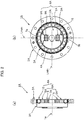
FIG. 1(a) is a schematic longitudinal cross-sectional view of a strain wave gearing which has a sliding-contact type wave generator provided with two piezoelectric elements, andFIG. 1(b) is a schematic end view thereof; -
FIG. 2(a) is a schematic longitudinal cross-sectional view of a strain wave gearing which has a rolling-contact type wave generator provided with two piezoelectric elements, andFIG. 2(b) is a schematic end view thereof; -
FIG. 3A is a schematic end view of a strain wave gearing which has a sliding-contact type wave generator provided with a single piezoelectric element; -
FIG. 3B is a schematic end view of a strain wave gearing which has a rolling-contact type wave generator provided with a single piezoelectric element; -
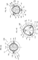
FIG. 4A is an explanatory view illustrating another example of a strain wave gearing provided with a sliding-contact type wave generator; -
FIG. 4B is an explanatory view illustrating still another example of a strain wave gearing provided with a sliding-contact type wave generator; and -
FIG. 4C is an explanatory view illustrating another example of a strain wave gearing provided with a sliding-contact type wave generator. - Embodiments of a strain wave gearing according to the present invention will be described with reference to the drawings. The following embodiments relate to a cup-type strain wave gearing. The present invention can also be applied to a silk-hat type strain wave gearing and a flat-type strain wave gearing in a similar manner.
-
FIG. 1(a) is a schematic longitudinal cross-sectional view of a strain wave gearing according to an embodiment of the present invention, andFIG. 1(b) is a schematic end view thereof. A strain wave gearing 1 is provided with an annular rigid internally toothed gear 2 (rigid gear), a cup-shaped flexible externally toothed gear 3 (flexible gear) disposed coaxially inside the internally toothed gear, and awave generator 4 fitted coaxially into the externally toothed gear. The internallytoothed gear 2 and the externallytoothed gear 3 are supported by a not-shown support member in a relatively rotatable state about a devicecenter axis line 1a. The externallytoothed gear 3 has a cylindrical body andexternal teeth 3a formed on the cylindrical body, and thewave generator 4 is fitted into the innerperipheral surface 3b of the cylindrical body where the external teeth are formed. The externallytoothed gear 3 and thewave generator 4 are also relatively rotatable about the devicecenter axis line 1a. - The
wave generator 4 makes the externallytoothed gear 3 to flex into a shape along an elliptical shape and mesh with the internallytoothed gear 2 at positions on both ends of a major axis Lmax of the elliptical shape. When thewave generator 4 rotates, two meshingportions toothed gear 3 with the internallytoothed gear 2 are moved in the circumferential direction of the internallytoothed gear 2. This causes relative rotation to occur between the twogears gears - The
wave generator 4 has a rigid plug 6 (rotating body) provided with an elliptical outer peripheral surface. Theplug 6 is constituted by: aplug body member 7 forming a plug main portion excluding plug end portions located on both sides in the direction of the major axis Lmax; and twogear pressing members 8 forming the plug end portions on the both sides in the direction of the major axis Lmax. Theplug 6 is also provided with two piezoelectric elements 9 (excitation units) to generate ultrasonic vibration along the direction of the major axis Lmax in thegear pressing members 8.Power supply lines piezoelectric elements 9. Thepiezoelectric elements 9 are controlled to drive by a not-shown controller. - The
plug body member 7 is of a line-symmetrical shape with respect to the major axis Lmax and the minor axis Lmin, respectively, and ashaft hole 11 is formed in the center of the plug body member to fixedly connect a motor shaft or other input shaft. Theplug body member 7 is formed with mountingrecesses 12 for mounting thepiezoelectric elements 9 and thegear pressing members 8 on both sides of theshaft hole 11 in the direction of the major axis Lmax. Theplug body member 7 has outerperipheral surface portions 13 on both sides of the mounting recesses 12, the outer peripheral surface portions defining an elliptical outer peripheral surface. Each of the mounting recesses 12 is formed with a wide-width outer-peripheral-side recess part 12a and a narrow-width center-side recess part 12b. - The
piezoelectric elements 9 are respectively mounted in the center-side recess parts 12b. Thepiezoelectric elements 9 generate one-axis ultrasonic vibration (vibration frequency is from 20kHz to 80kHz). The piezoelectric elements are of a laminated type having a shape of a quadrangular prism, a cylinder or a ring. Thepiezoelectric elements 9 are mounted in the center-side recess parts 12b so that the direction of vibration thereof is in line with the direction of the major axis Lmax and are supported by therecess bottom surfaces 12f thereof. Each of thegear pressing members 8 is shaped so that it can be fixed into the outer-peripheral-side recess part 12a and a part of the center-side recess part 12b, and the outerperipheral surface 8a of the gear pressing member defines one end portion in the direction of the major axis Lmax of an elliptical outer peripheral surface of theplug 6. - Each of the
gear pressing members 8 has a side surface having a shape that is complemental to a stepped side surface of the mountingrecess 12. Thegear pressing member 8 has left and rightside surface portions gear pressing member 8, and the side surface portions are in contact withside surface portions recess part 12. Theseside surface portions gear pressing members 8 to displace (slide) along only the direction of the major axis Lmax. - The left and right stepped side surfaces of the mounting
recess 12 have a steppedsurface portion 12e facing outward in the radial direction, the stepped surface portion determining the position of thegear pressing member 8 in the major axis direction. In the present embodiment, there is formed a state in which the reaction force that acts on thegear pressing member 8 from the elliptically flexed externallytoothed gear 3, is applied to thepiezoelectric element 9 as a preliminary load. In a state in which left andright jaw portions 8e of thegear pressing member 8 are in contact with the steppedportion 12e, the outerperipheral surface 8a of the gear pressing member is smoothly connected to the outerperipheral surface 13 of theplug body member 7 and thetip end surface 9a of thepiezoelectric element 9 are pressed by thebottom surface 8f of thegear pressing member 8. - The outer
peripheral surface 8a of thegear pressing member 8 has a circumferential length that is set to be a length across an angle θ of 35 degrees left and right from the major axis Lmax. In the consideration of a radial load distribution when the strain wave gearing 1 operates under load being applied, a large radial load is applied to a portion within this angle range. It is therefore possible to apply ultrasonic vibration in the direction of the major axis Lmax to a portion where a large radial load occurs. In addition, at the side of theplug body member 7 that slidably supports thegear pressing members 8, it is possible to reliably obtain a sufficient guide part to guide thegear pressing members 8 in the major-axis direction. - In the strain wave gearing 1, the externally
toothed gear 3 is flexed into an elliptical shape by thegear pressing members 8 located at both ends of the major axis Lmax in theplug 6 of thewave generator 4, so that the meshingportions toothed gear 2 are formed at two locations. When theplug 6 is rotated by a motor or the like, thegear pressing members 8, which are in sliding-contact with the innerperipheral surface 3b of the externallytoothed gear 3, is also rotated together with theplug 6 to move themeshing portions portions gears gears toothed gear 2 and the externallytoothed gear 3 is 2n (n is a positive integer). For example, a reduced-speed rotation can be taken out from the externallytoothed gear 3 when the internallytoothed gear 2 is fixed so as not to rotate. - During operation of the strain wave gearing 1, the
piezoelectric elements 9 are supplied with electric power to generate ultrasonic vibration. The ultrasonic vibration is applied to thegear pressing members 8 which are in contact with thepiezoelectric elements 9. As a result of a squeeze film effect, in each contact site between the outerperipheral surface 8a of thegear pressing member 8 and the innerperipheral surface 3b of the externallytoothed gear 3, an apparent friction coefficient of each contact surface is greatly reduced. The rotational torque of thewave generator 4 can therefore be reduced. In addition, thepiezoelectric elements 9 are of a laminated type, which is effective to improve rigidity of theplug 6 and to reduce the weight thereof. - According to the experiments conducted by the present inventor, it was confirmed that the friction coefficient of the contact surfaces between the
gear pressing member 8 and thewave generator 4 can be greatly reduced as shown in the following table. In addition, when thegear pressing member 8 is vibrated ultrasonically, specifically vibrated at vibration frequency of 20kHz or more, it was confirmed that the vibration and noise of the strain wave gearing 1 did not have such an adverse effect that would impede practical use.<friction coefficient ratio and vibration frequency(experimental example)> Frequency Non-lubricating state Lubricating state Off 1 1 28kHz 0.13 0.3 45kHz 0.15 0.2 100kHz 0.46 0.68 - The present invention is also effective in a strain wave gearing provided with a wave generator of a rolling-contact type.
FIG. 2(a) is a schematic longitudinal cross-sectional view of a strain wave gearing having a rolling-contact type wave generator provided with two piezoelectric elements, andFIG. 2(b) is a schematic end view thereof. A strain wave gearing 1A is provided with a rigid internallytoothed gear 2A, a flexible externallytoothed gear 3A and a rolling-contacttype wave generator 4A. Thewave generator 4A is provided with arigid plug 6A (rotating body) having an elliptical outer peripheral surface and a rollingbearing 16 mounted on the outer peripheral surface of the plug. The rollingbearing 16 is a ball bearing, for example. A roller bearing can also be used. - The
plug 6A is constituted by aplug body member 7A forming a main portion of the plug excluding plug end portions on both sides in the direction of the major axis Lmax of an elliptical shape of the plug, and twogear pressing members 8A forming the plug end portions on the both sides in the direction of the major axis Lmax. In addition, theplug 6A is provided with twopiezoelectric elements 9A (excitation units) to generate ultrasonic vibration in thegear pressing members 8A in the direction of the major axis Lmax. Thegear pressing members 8A are attached to theplug body members 7A so that they are slidable only in the direction of the major axis Lmax. - In this case, in each portion along the major-axis direction of the strain wave gearing 1A, the component parts are in contact with each other, and ultrasonic vibration in the direction of the major axis Lmax is transmitted to each parts (raceway parts of the rolling bearing of the wave generator, an outer race of the rolling bearing and the inner peripheral surface of the internally toothed gear, tooth surfaces). Therefore, rotational torque of the
wave generator 4A can be reduced even in a case of the strain wave gearing 1A provided with the rolling-contacttype wave generator 4A in which rollers are made to roll to generate wave motion. - In the
strain wave gearings FIGS. 1 and2 , twopiezoelectric elements 9 or twopiezoelectric elements 9A are used. A single piezoelectric element can be used. For example, a strain wave gearing 1B illustrated inFIG. 3A is provided with a rigid internallytoothed gear 2B, a flexible externallytoothed gear 3B and a sliding-contacttype wave generator 4B. Thewave generator 4B is provided with arigid plug 6B that has aplug body member 7B formed with a mountingrecess part 12B continuously passing through the center of the plug body member along the direction of the major axis Lmax. The mountingrecess part 12B has a narrow-width portion in which onepiezoelectric element 9B is mounted and wide-width portions on both sides thereof in which gear pressingmembers 8B are mounted. Thegear pressing members 8B are arranged on both sides of thepiezoelectric element 8B in a manner sandwiching the same therebetween. -
FIG. 3B illustrates a strain wave gearing 1C which has a rigid internally toothed gear 2C, a flexible externallytoothed gear 3C and a rolling-contacttype wave generator 4C provided with one piezoelectric element. Thewave generator 4C is provided with arigid plug 6C, and a rolling bearing 16C mounted on an elliptical outer peripheral surface of theplug 6C. Theplug 6C has aplug body member 7C that is formed with a mountingrecess 12C continuously passing through the center thereof along the direction of the major axis Lmax. A singlepiezoelectric element 9C is mounted in a narrow-width portion of the mountingrecess 12C andgear pressing members 8C are mounted in wide-width portions on both sides of the mounting recess. Thegear pressing members 8C are arranged on both sides of thepiezoelectric member 9C to sandwich the same therebetween. - Next,
FIG. 4A is an explanatory view illustrating another embodiment of a strain wave gearing to which the present invention is applied. A strain wave gearing 100A has a rigid externally toothed gear 122 (rigid gear) disposed on the innermost side thereof. An annular flexible internally toothed gear 123 (flexible gear) is disposed to coaxially surround the externallytoothed gear 122. Anannular wave generator 124 is disposed to coaxially surround the internallytoothed gear 123. - The internally
toothed gear 123 is flexed by thewave generator 124 into an elliptical shape, for example. The internallytoothed gear 123 flexed by thewave generator 124 is formed with meshing portions where the internally toothed gear meshes with the externallytoothed gear 122 at two locations on both ends of the minor axis of the elliptical shape. The meshingportions FIG. 4A . - The
wave generator 124 is provided with an annular rigid cam plate 126 (rotating body) . Thecam plate 126 has an innerperipheral surface 126a of an elliptical shape. Thecam plate 126 is constituted by: cam-plate body member 127;gear pressing members 128 mounted in portions of the cam-plate body member 127, the portions being located on both sides in the direction of the minor axis Lmin; and piezoelectric elements 129 (excitation units) to apply ultrasonic vibration to thegear pressing members 128 in the direction of the minor axis Lmin. The rotational torque of the sliding-contacttype wave generator 124 can be reduced by applying ultrasonic vibration to thegear pressing members 128. - The present invention may be applied in a case in which the strain wave gearing 100A is provided with a rolling-contact type wave generator. In this case, the wave generator is constituted to have an annular rigid cam plate (rotating body) and a rolling bearing mounted inside the cam plate.
- Next, the present invention can also be applied to a strain wave gearing in which a flexible gear meshes with a rigid gear at three or more locations. For example, the present invention can be applied to a strain wave gearing in which meshing of teeth between an internally toothed gear and an externally toothed gear are formed at three locations. A strain wave gearing 100B illustrated in
FIG. 4B has a rigid internally toothed gear 142 (rigid gear), a flexible externally toothed gear 143 (flexible gear) disposed inside the internally toothed gear, and a non-circularcontoured wave generator 144 fitted inside the externally toothed gear. The externallytoothed gear 143 has a portion where external teeth are formed, the portion being flexed by thewave generator 144 into a non-circular shape. - The
wave generator 144 is provided with a non-circular contouredrigid plug 146. The non-circular outerperipheral surface 146a of theplug 146 is defined by a closed curve which can be inscribed on a true circle at plural locations at equal angular intervals along the circumferential direction of the true circle. The externallytoothed gear 143 is flexed by theplug 146 into a non-circular shape, whereby meshingportions toothed gear 142 are formed at three locations at 120-degree angular intervals. - The
plug 146 is constituted by: aplug body member 147 forming a plug main portion excluding three plug lobe portions; and threegear pressing members 148 forming the respective plug lobe portions. Thewave generator 144 is provided with piezoelectric elements 149 (excitation units) to generate radial ultrasonic vibration in thegear pressing members 148. The rotational torque of the sliding-contacttype wave generator 144 can be reduced by applying ultrasonic vibration to thegear pressing members 148. - In addition, the present invention can also be applied to a strain wave gearing as illustrated in
FIG. 4C . A strain wave gearing 100C of this figure has a rigid externally toothed gear 162 (rigid gear), a flexible internally toothed gear 163 (flexible gear) disposed outside the rigid externally toothed gear, and awave generator 164 which has a non-circular contoured inner peripheral surface and is disposed outside the internallytoothed gear 163. - The
wave generator 164 has arigid cam plate 166 provided with a non-circular innerperipheral surface 166a. The non-circular innerperipheral surface 166a of thecam plate 166 is defined by a closed curve which can circumscribe a true circle at three locations at equal angular intervals. - With the
wave generator 164 of this shape, the internallytoothed gear 163 is flexed into a shape along the non-circular contour of thewave generator 164, whereby meshingportions toothed gear 162 are formed at three locations at 120-degree angular intervals. Thecam plate 166 is constituted by a cam-plate body member 167 and threegear pressing members 168. In addition, thecam plate 166 is provided with piezoelectric elements 169 (excitation units) to generate ultrasonic vibration in thegear pressing members 168. The rotational torque of the sliding-contacttype wave generator 164 can be reduced by applying ultrasonic vibration to thegear pressing members 168. - The present invention can also be applied to a strain wave gearing in which a flexible gear is meshed with a rigid gear at four or more locations. In this case, a non-circular outer peripheral surface or a non-circular inner peripheral surface is defined by a closed curve which can be inscribed or circumscribed on a true circle at four or more locations at equal angular intervals along the circumferential direction.
Claims (6)
- A strain wave gearing comprising:a rigid gear;a flexible gear that is disposed coaxially with the rigid gear and is rotatable relative to the rigid gear about a center axis line of the rigid gear; anda wave generator that is disposed coaxially with the flexible gear and is rotatable relative to the flexible gear about the center axis line,wherein the wave generator comprises:a plurality of gear pressing parts that flex the flexible gear in a radial direction at positions at equal angular intervals in a circumferential direction to form a plurality of meshing portions where the flexible gear meshes with the rigid gear; andan excitation unit that generates ultrasonic vibration of 20kHz to 80kHz in the respective gear pressing parts in the radial direction.
- The strain wave gearing according to claim 1,
wherein the wave generator has a rotating body having the center axis line as a rotation center;
the gear pressing parts are gear pressing members that are attached to positions of the rotating body in a slidable state in the radial direction, the positions being located at equal angular intervals in a circumferential direction of the rotating body;
the excitation unit is one or a plurality of piezoelectric elements attached to the rotating body, the piezoelectric elements being able to displace in one axial direction; and
the piezoelectric elements are linked to the gear pressing members in a state in which a direction of displacement thereof is coincident with the radial direction. - The strain wave gearing according to claim 2,
wherein the rigid gear is an internally toothed gear; the flexible gear is an externally toothed gear disposed inside the internally toothed gear;
the wave generator has a rigid plug as the rotating body, the rigid plug being mounted inside the externally toothed gear and being provided with an outer peripheral surface having an elliptical shape;
the rigid plug has: a plug body member forming a main portion excluding end portions located on both sides of a major-axis direction of the elliptical shape; and two of the gear pressing members forming the end portions on the both sides of the major-axis direction;
the gear pressing members are attached to the plug body member in a slidable state in the major-axis direction; and
the piezoelectric element is attached to the plug body member at a position between the gear pressing members so that the direction of displacement is coincide with the major-axis direction. - The strain wave gearing according to claim 3,
wherein the piezoelectric element is applied with a compression force as a preliminary load; and
the preliminary load is a reaction force applied to the piezoelectric element, via the gear pressing members, from the externally toothed gear that is flexed into the elliptical shape. - The strain wave gearing according to claim 3,
wherein the gear pressing members have an outer peripheral surface, a circumferential length of the outer peripheral surface being a length extending across an angular range of 30 degrees to 40 degrees left and right from a major axis of the elliptical shape. - The strain wave gearing according to claim 3,
wherein the wave generator has a rolling bearing mounted between the outer peripheral surface of the rigid plug and an inner peripheral surface of the externally toothed gear.
Applications Claiming Priority (1)
| Application Number | Priority Date | Filing Date | Title |
|---|---|---|---|
| PCT/JP2017/022394 WO2018229987A1 (en) | 2017-06-16 | 2017-06-16 | Wave gear device |
Publications (4)
| Publication Number | Publication Date |
|---|---|
| EP3614019A1 true EP3614019A1 (en) | 2020-02-26 |
| EP3614019A4 EP3614019A4 (en) | 2020-10-14 |
| EP3614019B1 EP3614019B1 (en) | 2023-08-02 |
| EP3614019C0 EP3614019C0 (en) | 2023-08-02 |
Family
ID=64659073
Family Applications (1)
| Application Number | Title | Priority Date | Filing Date |
|---|---|---|---|
| EP17913875.5A Active EP3614019B1 (en) | 2017-06-16 | 2017-06-16 | Wave gear device |
Country Status (7)
| Country | Link |
|---|---|
| US (1) | US10935121B2 (en) |
| EP (1) | EP3614019B1 (en) |
| JP (1) | JP6707312B2 (en) |
| KR (1) | KR102303733B1 (en) |
| CN (1) | CN110730878B (en) |
| TW (1) | TWI756410B (en) |
| WO (1) | WO2018229987A1 (en) |
Families Citing this family (2)
| Publication number | Priority date | Publication date | Assignee | Title |
|---|---|---|---|---|
| AT521617B1 (en) * | 2019-07-26 | 2020-03-15 | Univ Graz Tech | COAXIAL GEARBOX |
| CN111059250B (en) * | 2019-12-10 | 2024-06-07 | 深圳市山卓谐波传动科技有限公司 | Cam, harmonic reducer, cam design method and reducer installation method |
Family Cites Families (15)
| Publication number | Priority date | Publication date | Assignee | Title |
|---|---|---|---|---|
| US3166949A (en) * | 1964-04-09 | 1965-01-26 | Roger H Lapp | Harmonic drive adjusting means |
| JPH01158250A (en) * | 1987-12-15 | 1989-06-21 | Haamonitsuku Drive Syst:Kk | Flexible gear |
| JPH02129436A (en) * | 1988-11-08 | 1990-05-17 | Sumitomo Heavy Ind Ltd | Actuator |
| JP2714429B2 (en) * | 1989-03-31 | 1998-02-16 | 株式会社ハーモニック・ドライブ・システムズ | Wave gear device |
| JP3422078B2 (en) | 1994-06-23 | 2003-06-30 | 三菱電機株式会社 | Decelerator |
| DE19747566C1 (en) * | 1997-10-28 | 1999-04-08 | Fraunhofer Ges Forschung | Piezo driven tension wave drive with rigid splined unit and flexible unit having splines also wave generator |
| DE60006640T2 (en) * | 2000-02-29 | 2004-09-23 | Harmonic Drive Technologies, Peabody | Piezoelectric drive arrangement for wave gear |
| US20120204674A1 (en) * | 2007-12-05 | 2012-08-16 | Ivan Lundberg | Harmonic motor, drive assembly, industrial robot, robot boom and robot joint |
| JP2012067849A (en) * | 2010-09-24 | 2012-04-05 | Aisin Seiki Co Ltd | Rotary driving device |
| US8733207B2 (en) * | 2011-03-23 | 2014-05-27 | Toyota Jidosha Kabushiki Kaisha | Method of driving joint device |
| TWI619343B (en) * | 2014-03-10 | 2018-03-21 | Harmonic Drive Systems | Wave gear device for vibration power generation and friction-clamping wave device |
| KR20160145668A (en) * | 2014-04-09 | 2016-12-20 | 캘리포니아 인스티튜트 오브 테크놀로지 | Systems and methods for implementing bulk metallic glass-based strain wave gears and strain wave gear components |
| JP2016217391A (en) | 2015-05-16 | 2016-12-22 | 株式会社前田精密製作所 | Wave generation device of wave speed reducer |
| CN107152456B (en) * | 2017-07-25 | 2023-04-18 | 顺德职业技术学院 | Porous ultrasonic bearing |
| CN108397536B (en) * | 2018-05-04 | 2023-07-25 | 顺德职业技术学院 | Harmonic Drive Mechanism of New Wave Generator |
-
2017
- 2017-06-16 WO PCT/JP2017/022394 patent/WO2018229987A1/en not_active Ceased
- 2017-06-16 US US16/611,248 patent/US10935121B2/en active Active
- 2017-06-16 EP EP17913875.5A patent/EP3614019B1/en active Active
- 2017-06-16 KR KR1020197032926A patent/KR102303733B1/en active Active
- 2017-06-16 CN CN201780090744.9A patent/CN110730878B/en active Active
- 2017-06-16 JP JP2019524706A patent/JP6707312B2/en active Active
-
2018
- 2018-04-25 TW TW107113939A patent/TWI756410B/en active
Also Published As
| Publication number | Publication date |
|---|---|
| US20200158220A1 (en) | 2020-05-21 |
| KR102303733B1 (en) | 2021-09-16 |
| CN110730878A (en) | 2020-01-24 |
| EP3614019B1 (en) | 2023-08-02 |
| JPWO2018229987A1 (en) | 2020-03-19 |
| EP3614019C0 (en) | 2023-08-02 |
| CN110730878B (en) | 2022-08-19 |
| EP3614019A4 (en) | 2020-10-14 |
| WO2018229987A1 (en) | 2018-12-20 |
| KR20190132510A (en) | 2019-11-27 |
| TWI756410B (en) | 2022-03-01 |
| TW201905353A (en) | 2019-02-01 |
| JP6707312B2 (en) | 2020-06-10 |
| US10935121B2 (en) | 2021-03-02 |
Similar Documents
| Publication | Publication Date | Title |
|---|---|---|
| JP3768261B2 (en) | Flat type wave gear device | |
| CN1902415B (en) | Eccentric oscillating gear unit | |
| JP7081878B2 (en) | Wave gear device | |
| JP2866246B2 (en) | Speed reducer series with internal meshing planetary gear structure | |
| JP2013057397A (en) | Wave gear speed reducer | |
| KR20140001202A (en) | Wave gear device and flexible externally toothed gear | |
| WO2014006833A1 (en) | Eccentric oscillating gear device | |
| JP2017044287A (en) | Wave gear transmission | |
| EP3614019B1 (en) | Wave gear device | |
| JPH0627532B2 (en) | Planetary gearbox | |
| RU2659196C1 (en) | Dual harmonic gear drive | |
| JP2017025971A (en) | Reduction gear | |
| JP7068102B2 (en) | Hypocycloid reducer | |
| JP7468827B2 (en) | Strained gear device | |
| KR102345641B1 (en) | Tractional strain wave reducer | |
| KR101908843B1 (en) | 2 Step Cycloid Reducer | |
| JP2012067899A (en) | Step-up/reduction gear | |
| JP2022526063A (en) | Friction wave reducer | |
| JP3897924B2 (en) | Inner meshing planetary gear unit | |
| JP7207628B2 (en) | transmission | |
| JP2771395B2 (en) | Inner mesh planetary gear structure | |
| CN114370487B (en) | Harmonic reducer and transmission device | |
| WO2020111129A1 (en) | Wave gear device | |
| KR20210112801A (en) | Tractional strain wave reducer | |
| JP2009287631A (en) | Eccentric oscillation type gear device |
Legal Events
| Date | Code | Title | Description |
|---|---|---|---|
| STAA | Information on the status of an ep patent application or granted ep patent |
Free format text: STATUS: THE INTERNATIONAL PUBLICATION HAS BEEN MADE |
|
| PUAI | Public reference made under article 153(3) epc to a published international application that has entered the european phase |
Free format text: ORIGINAL CODE: 0009012 |
|
| STAA | Information on the status of an ep patent application or granted ep patent |
Free format text: STATUS: REQUEST FOR EXAMINATION WAS MADE |
|
| 17P | Request for examination filed |
Effective date: 20191122 |
|
| AK | Designated contracting states |
Kind code of ref document: A1 Designated state(s): AL AT BE BG CH CY CZ DE DK EE ES FI FR GB GR HR HU IE IS IT LI LT LU LV MC MK MT NL NO PL PT RO RS SE SI SK SM TR |
|
| AX | Request for extension of the european patent |
Extension state: BA ME |
|
| REG | Reference to a national code |
Ref country code: DE Ref legal event code: R079 Free format text: PREVIOUS MAIN CLASS: F16H0001320000 Ipc: F16H0049000000 Ref country code: DE Ref legal event code: R079 Ref document number: 602017072337 Country of ref document: DE Free format text: PREVIOUS MAIN CLASS: F16H0001320000 Ipc: F16H0049000000 |
|
| DAV | Request for validation of the european patent (deleted) | ||
| DAX | Request for extension of the european patent (deleted) | ||
| A4 | Supplementary search report drawn up and despatched |
Effective date: 20200915 |
|
| RIC1 | Information provided on ipc code assigned before grant |
Ipc: F16H 49/00 20060101AFI20200909BHEP |
|
| STAA | Information on the status of an ep patent application or granted ep patent |
Free format text: STATUS: EXAMINATION IS IN PROGRESS |
|
| 17Q | First examination report despatched |
Effective date: 20210315 |
|
| GRAP | Despatch of communication of intention to grant a patent |
Free format text: ORIGINAL CODE: EPIDOSNIGR1 |
|
| STAA | Information on the status of an ep patent application or granted ep patent |
Free format text: STATUS: GRANT OF PATENT IS INTENDED |
|
| INTG | Intention to grant announced |
Effective date: 20230125 |
|
| GRAS | Grant fee paid |
Free format text: ORIGINAL CODE: EPIDOSNIGR3 |
|
| GRAA | (expected) grant |
Free format text: ORIGINAL CODE: 0009210 |
|
| STAA | Information on the status of an ep patent application or granted ep patent |
Free format text: STATUS: THE PATENT HAS BEEN GRANTED |
|
| AK | Designated contracting states |
Kind code of ref document: B1 Designated state(s): AL AT BE BG CH CY CZ DE DK EE ES FI FR GB GR HR HU IE IS IT LI LT LU LV MC MK MT NL NO PL PT RO RS SE SI SK SM TR |
|
| REG | Reference to a national code |
Ref country code: GB Ref legal event code: FG4D |
|
| REG | Reference to a national code |
Ref country code: CH Ref legal event code: EP |
|
| REG | Reference to a national code |
Ref country code: DE Ref legal event code: R096 Ref document number: 602017072337 Country of ref document: DE |
|
| REG | Reference to a national code |
Ref country code: IE Ref legal event code: FG4D |
|
| U01 | Request for unitary effect filed |
Effective date: 20230830 |
|
| U07 | Unitary effect registered |
Designated state(s): AT BE BG DE DK EE FI FR IT LT LU LV MT NL PT SE SI Effective date: 20230906 |
|
| PG25 | Lapsed in a contracting state [announced via postgrant information from national office to epo] |
Ref country code: GR Free format text: LAPSE BECAUSE OF FAILURE TO SUBMIT A TRANSLATION OF THE DESCRIPTION OR TO PAY THE FEE WITHIN THE PRESCRIBED TIME-LIMIT Effective date: 20231103 |
|
| PG25 | Lapsed in a contracting state [announced via postgrant information from national office to epo] |
Ref country code: IS Free format text: LAPSE BECAUSE OF FAILURE TO SUBMIT A TRANSLATION OF THE DESCRIPTION OR TO PAY THE FEE WITHIN THE PRESCRIBED TIME-LIMIT Effective date: 20231202 |
|
| PG25 | Lapsed in a contracting state [announced via postgrant information from national office to epo] |
Ref country code: RS Free format text: LAPSE BECAUSE OF FAILURE TO SUBMIT A TRANSLATION OF THE DESCRIPTION OR TO PAY THE FEE WITHIN THE PRESCRIBED TIME-LIMIT Effective date: 20230802 Ref country code: NO Free format text: LAPSE BECAUSE OF FAILURE TO SUBMIT A TRANSLATION OF THE DESCRIPTION OR TO PAY THE FEE WITHIN THE PRESCRIBED TIME-LIMIT Effective date: 20231102 Ref country code: IS Free format text: LAPSE BECAUSE OF FAILURE TO SUBMIT A TRANSLATION OF THE DESCRIPTION OR TO PAY THE FEE WITHIN THE PRESCRIBED TIME-LIMIT Effective date: 20231202 Ref country code: HR Free format text: LAPSE BECAUSE OF FAILURE TO SUBMIT A TRANSLATION OF THE DESCRIPTION OR TO PAY THE FEE WITHIN THE PRESCRIBED TIME-LIMIT Effective date: 20230802 Ref country code: GR Free format text: LAPSE BECAUSE OF FAILURE TO SUBMIT A TRANSLATION OF THE DESCRIPTION OR TO PAY THE FEE WITHIN THE PRESCRIBED TIME-LIMIT Effective date: 20231103 |
|
| PG25 | Lapsed in a contracting state [announced via postgrant information from national office to epo] |
Ref country code: PL Free format text: LAPSE BECAUSE OF FAILURE TO SUBMIT A TRANSLATION OF THE DESCRIPTION OR TO PAY THE FEE WITHIN THE PRESCRIBED TIME-LIMIT Effective date: 20230802 |
|
| PG25 | Lapsed in a contracting state [announced via postgrant information from national office to epo] |
Ref country code: ES Free format text: LAPSE BECAUSE OF FAILURE TO SUBMIT A TRANSLATION OF THE DESCRIPTION OR TO PAY THE FEE WITHIN THE PRESCRIBED TIME-LIMIT Effective date: 20230802 |
|
| PG25 | Lapsed in a contracting state [announced via postgrant information from national office to epo] |
Ref country code: SM Free format text: LAPSE BECAUSE OF FAILURE TO SUBMIT A TRANSLATION OF THE DESCRIPTION OR TO PAY THE FEE WITHIN THE PRESCRIBED TIME-LIMIT Effective date: 20230802 Ref country code: RO Free format text: LAPSE BECAUSE OF FAILURE TO SUBMIT A TRANSLATION OF THE DESCRIPTION OR TO PAY THE FEE WITHIN THE PRESCRIBED TIME-LIMIT Effective date: 20230802 Ref country code: ES Free format text: LAPSE BECAUSE OF FAILURE TO SUBMIT A TRANSLATION OF THE DESCRIPTION OR TO PAY THE FEE WITHIN THE PRESCRIBED TIME-LIMIT Effective date: 20230802 Ref country code: CZ Free format text: LAPSE BECAUSE OF FAILURE TO SUBMIT A TRANSLATION OF THE DESCRIPTION OR TO PAY THE FEE WITHIN THE PRESCRIBED TIME-LIMIT Effective date: 20230802 Ref country code: SK Free format text: LAPSE BECAUSE OF FAILURE TO SUBMIT A TRANSLATION OF THE DESCRIPTION OR TO PAY THE FEE WITHIN THE PRESCRIBED TIME-LIMIT Effective date: 20230802 |
|
| REG | Reference to a national code |
Ref country code: DE Ref legal event code: R097 Ref document number: 602017072337 Country of ref document: DE |
|
| U20 | Renewal fee for the european patent with unitary effect paid |
Year of fee payment: 8 Effective date: 20240423 |
|
| PLBE | No opposition filed within time limit |
Free format text: ORIGINAL CODE: 0009261 |
|
| STAA | Information on the status of an ep patent application or granted ep patent |
Free format text: STATUS: NO OPPOSITION FILED WITHIN TIME LIMIT |
|
| 26N | No opposition filed |
Effective date: 20240503 |
|
| PG25 | Lapsed in a contracting state [announced via postgrant information from national office to epo] |
Ref country code: MC Free format text: LAPSE BECAUSE OF FAILURE TO SUBMIT A TRANSLATION OF THE DESCRIPTION OR TO PAY THE FEE WITHIN THE PRESCRIBED TIME-LIMIT Effective date: 20230802 |
|
| REG | Reference to a national code |
Ref country code: CH Ref legal event code: PL |
|
| GBPC | Gb: european patent ceased through non-payment of renewal fee |
Effective date: 20240616 |
|
| PG25 | Lapsed in a contracting state [announced via postgrant information from national office to epo] |
Ref country code: IE Free format text: LAPSE BECAUSE OF NON-PAYMENT OF DUE FEES Effective date: 20240616 |
|
| PG25 | Lapsed in a contracting state [announced via postgrant information from national office to epo] |
Ref country code: CH Free format text: LAPSE BECAUSE OF NON-PAYMENT OF DUE FEES Effective date: 20240630 |
|
| PG25 | Lapsed in a contracting state [announced via postgrant information from national office to epo] |
Ref country code: GB Free format text: LAPSE BECAUSE OF NON-PAYMENT OF DUE FEES Effective date: 20240616 |
|
| U20 | Renewal fee for the european patent with unitary effect paid |
Year of fee payment: 9 Effective date: 20250627 |
|
| PG25 | Lapsed in a contracting state [announced via postgrant information from national office to epo] |
Ref country code: CY Free format text: LAPSE BECAUSE OF FAILURE TO SUBMIT A TRANSLATION OF THE DESCRIPTION OR TO PAY THE FEE WITHIN THE PRESCRIBED TIME-LIMIT; INVALID AB INITIO Effective date: 20170616 |
|
| PG25 | Lapsed in a contracting state [announced via postgrant information from national office to epo] |
Ref country code: HU Free format text: LAPSE BECAUSE OF FAILURE TO SUBMIT A TRANSLATION OF THE DESCRIPTION OR TO PAY THE FEE WITHIN THE PRESCRIBED TIME-LIMIT; INVALID AB INITIO Effective date: 20170616 |