EP3613963A1 - Internal combustion engine control method and internal combustion engine control device - Google Patents
Internal combustion engine control method and internal combustion engine control device Download PDFInfo
- Publication number
- EP3613963A1 EP3613963A1 EP17905991.0A EP17905991A EP3613963A1 EP 3613963 A1 EP3613963 A1 EP 3613963A1 EP 17905991 A EP17905991 A EP 17905991A EP 3613963 A1 EP3613963 A1 EP 3613963A1
- Authority
- EP
- European Patent Office
- Prior art keywords
- internal combustion
- combustion engine
- exhaust
- wastegate valve
- valve
- Prior art date
- Legal status (The legal status is an assumption and is not a legal conclusion. Google has not performed a legal analysis and makes no representation as to the accuracy of the status listed.)
- Granted
Links
Images




Classifications
-
- F—MECHANICAL ENGINEERING; LIGHTING; HEATING; WEAPONS; BLASTING
- F02—COMBUSTION ENGINES; HOT-GAS OR COMBUSTION-PRODUCT ENGINE PLANTS
- F02B—INTERNAL-COMBUSTION PISTON ENGINES; COMBUSTION ENGINES IN GENERAL
- F02B37/00—Engines characterised by provision of pumps driven at least for part of the time by exhaust
- F02B37/12—Control of the pumps
- F02B37/18—Control of the pumps by bypassing exhaust from the inlet to the outlet of turbine or to the atmosphere
-
- F—MECHANICAL ENGINEERING; LIGHTING; HEATING; WEAPONS; BLASTING
- F02—COMBUSTION ENGINES; HOT-GAS OR COMBUSTION-PRODUCT ENGINE PLANTS
- F02B—INTERNAL-COMBUSTION PISTON ENGINES; COMBUSTION ENGINES IN GENERAL
- F02B37/00—Engines characterised by provision of pumps driven at least for part of the time by exhaust
- F02B37/12—Control of the pumps
- F02B37/18—Control of the pumps by bypassing exhaust from the inlet to the outlet of turbine or to the atmosphere
- F02B37/183—Arrangements of bypass valves or actuators therefor
-
- F—MECHANICAL ENGINEERING; LIGHTING; HEATING; WEAPONS; BLASTING
- F02—COMBUSTION ENGINES; HOT-GAS OR COMBUSTION-PRODUCT ENGINE PLANTS
- F02B—INTERNAL-COMBUSTION PISTON ENGINES; COMBUSTION ENGINES IN GENERAL
- F02B37/00—Engines characterised by provision of pumps driven at least for part of the time by exhaust
- F02B37/12—Control of the pumps
- F02B37/24—Control of the pumps by using pumps or turbines with adjustable guide vanes
-
- F—MECHANICAL ENGINEERING; LIGHTING; HEATING; WEAPONS; BLASTING
- F02—COMBUSTION ENGINES; HOT-GAS OR COMBUSTION-PRODUCT ENGINE PLANTS
- F02D—CONTROLLING COMBUSTION ENGINES
- F02D41/00—Electrical control of supply of combustible mixture or its constituents
- F02D41/0002—Controlling intake air
- F02D41/0007—Controlling intake air for control of turbo-charged or super-charged engines
-
- F—MECHANICAL ENGINEERING; LIGHTING; HEATING; WEAPONS; BLASTING
- F02—COMBUSTION ENGINES; HOT-GAS OR COMBUSTION-PRODUCT ENGINE PLANTS
- F02M—SUPPLYING COMBUSTION ENGINES IN GENERAL WITH COMBUSTIBLE MIXTURES OR CONSTITUENTS THEREOF
- F02M26/00—Engine-pertinent apparatus for adding exhaust gases to combustion-air, main fuel or fuel-air mixture, e.g. by exhaust gas recirculation [EGR] systems
- F02M26/02—EGR systems specially adapted for supercharged engines
- F02M26/04—EGR systems specially adapted for supercharged engines with a single turbocharger
- F02M26/06—Low pressure loops, i.e. wherein recirculated exhaust gas is taken out from the exhaust downstream of the turbocharger turbine and reintroduced into the intake system upstream of the compressor
-
- Y—GENERAL TAGGING OF NEW TECHNOLOGICAL DEVELOPMENTS; GENERAL TAGGING OF CROSS-SECTIONAL TECHNOLOGIES SPANNING OVER SEVERAL SECTIONS OF THE IPC; TECHNICAL SUBJECTS COVERED BY FORMER USPC CROSS-REFERENCE ART COLLECTIONS [XRACs] AND DIGESTS
- Y02—TECHNOLOGIES OR APPLICATIONS FOR MITIGATION OR ADAPTATION AGAINST CLIMATE CHANGE
- Y02T—CLIMATE CHANGE MITIGATION TECHNOLOGIES RELATED TO TRANSPORTATION
- Y02T10/00—Road transport of goods or passengers
- Y02T10/10—Internal combustion engine [ICE] based vehicles
- Y02T10/12—Improving ICE efficiencies
Definitions
- the present invention relates to an internal combustion engine control method and an internal combustion engine control device for an internal combustion engine provided with a turbocharger.
- a patent document 1 discloses an internal combustion engine provided with a turbocharger and a wastegate valve, wherein the turbocharger is a variable nozzle type turbocharger structured to adjust a state of boost by adjusting a vane angle (or nozzle opening) of an exhaust turbine, and wherein the wastegate valve is structured to allow a part of exhaust gas to bypass the exhaust turbine of the turbocharger and flow into a downstream side of the exhaust turbine, wherein the exhaust gas is to be brought into the exhaust turbine.
- the turbocharger is a variable nozzle type turbocharger structured to adjust a state of boost by adjusting a vane angle (or nozzle opening) of an exhaust turbine
- the wastegate valve is structured to allow a part of exhaust gas to bypass the exhaust turbine of the turbocharger and flow into a downstream side of the exhaust turbine, wherein the exhaust gas is to be brought into the exhaust turbine.
- Patent document 1 discloses controlling the nozzle opening of the exhaust turbine and a valve opening of the wastegate valve when in a transient state.
- Patent Document 1 Japanese Patent Application Publication No. 2007-303330
- an internal combustion engine control method for an internal combustion engine including: a turbocharger including an exhaust turbine; a wastegate valve structured to allow a part of exhaust gas to bypass the exhaust turbine and flow into a downstream side of the exhaust turbine, wherein the exhaust gas is to be brought into the exhaust turbine; and an exhaust adjustment mechanism structured to adjust a quantity of the exhaust gas;
- the internal combustion engine control method comprises: operating a first one of the wastegate valve and the exhaust adjustment mechanism with higher priority to a second one of the wastegate valve and the exhaust adjustment mechanism in response to a condition where an intake air quantity is to be varied, wherein operation of the first one allows thermal energy to be recovered more efficiently under the condition than that of the second one.
- the present invention makes it possible to recover thermal energy efficiently as a work of boost pressure. This serves to reduce a pumping loss, and thereby enhance fuel efficiency of the internal combustion engine.
- FIG. 1 is an illustrative view schematically showing a general configuration of a control device for an internal combustion engine 1 according to the present invention, to which a control method for internal combustion engine 1 according to the present invention can be applied.
- Internal combustion engine 1 has an in-cylinder direct injection configuration in this example, wherein each cylinder is provided with a fuel injection valve not shown for injecting fuel into the cylinder.
- Internal combustion engine 1 is mounted as a drive source on a vehicle such as an automotive vehicle, and is provided with an intake passage 2 and an exhaust passage 3.
- Internal combustion engine 1 is connected to intake passage 2 in which an air cleaner 4, an air flow meter 5, and a throttle valve 6 are provided, wherein air cleaner 4 is structured to collect foreign matter contained in intake air, wherein air flow meter 5 is structured to sense an intake air quantity, and wherein throttle valve 6 is an electronic throttle valve structured to adjust the intake air quantity.
- Air flow meter 5 is arranged upstream of throttle valve 6.
- Air flow meter 5 includes a temperature sensor inside, and is structured to sense a temperature of intake air at an intake inlet.
- Air cleaner 4 is arranged upstream of air flow meter 5.
- Intake passage 2 is placed in an engine room in which internal combustion engine 1 is mounted.
- Internal combustion engine 1 is connected to exhaust passage 3 in which an upstream exhaust catalyst 7, a downstream exhaust catalyst 8, and a muffler 9 are provided, wherein upstream exhaust catalyst 7 is a three-way catalyst or the like, wherein downstream exhaust catalyst 8 is a NOx trap catalyst or the like, and wherein muffler 9 is structured to reduce an exhaust sound.
- Downstream exhaust catalyst 8 is arranged downstream of upstream exhaust catalyst 7.
- Muffler 9 is arranged downstream of downstream exhaust catalyst 8.
- turbocharger 10 Internal combustion engine 1 is further provided with a turbocharger 10 including a compressor 11 and an exhaust turbine 12, wherein compressor 11 and exhaust turbine 12 are arranged coaxially, wherein compressor 11 is disposed in intake passage 2, and exhaust turbine 12 is disposed in exhaust passage 3.
- Compressor 11 is arranged upstream of throttle valve 6 and downstream of air flow meter 5.
- Exhaust turbine 12 is arranged upstream of upstream exhaust catalyst 7.
- Turbocharger 10 is a variable capacity type turbocharger including a variable nozzle 13 structured to adjust a capacity of turbocharger 10. Specifically, when variable nozzle 13 is set to have a small nozzle opening, variable nozzle 13 has characteristics of small capacity suitable for a condition such as a low speed region where a flow rate of exhaust gas is low.
- variable nozzle 13 When variable nozzle 13 is set to have a large nozzle opening, variable nozzle 13 has characteristics of large capacity suitable for a condition such as a high speed region where the flow rate of exhaust gas is high.
- Variable nozzle 13 is structured to be driven by an actuator 14 of a diaphragm type that operates in response to a control pressure (or control negative pressure). The control pressure is generated via a pressure control valve 15 that is controlled by duty control.
- Pressure control valve 15 is controlled by a control unit 16 as a control section.
- variable nozzle 13 of turbocharger 10 is controlled by control unit 16.
- Variable nozzle 13 is an exhaust adjustment mechanism structured to adjust a quantity of exhaust gas that is to be brought into exhaust turbine 12 of turbocharger 10, and thereby control a boost pressure of internal combustion engine 1.
- Control unit 16 is a well-known digital computer that includes a CPU, a ROM, a RAM, and an input and output interface.
- an intercooler 17 is provided downstream of throttle valve 6, wherein intercooler 17 is structured to cool intake air compressed (or pressurized) by compressor 11, and thereby enhance efficiency of charging of intake air.
- Intercooler 17 is arranged in an intercooler cooling path (or auxiliary cooling path) 20 as well as a radiator (or intercooler radiator) 18 and an electric pump 19. Intercooler 17 is structured to be supplied with a coolant (cooling water) cooled by radiator 18.
- Intercooler cooling path 20 is structured to allow the coolant to circulate therein. Intercooler cooling path 20 is independent from a main cooling path not shown where cooling water circulates for cooling a cylinder block 21 of internal combustion engine 1.
- Radiator 18 is structured to cool the coolant in intercooler cooling path 20 by heat exchange with outside air.
- Electric pump 19 is structured to be driven to allow the coolant to circulate along an arrow A between radiator 18 and intercooler 17.
- Exhaust passage 3 is connected to an exhaust bypass passage 22 that bypasses the exhaust turbine 12 and connects an upstream side of exhaust turbine 12 to a downstream side of exhaust turbine 12.
- Exhaust bypass passage 22 has a downstream end connected to a portion of exhaust passage 3 upstream of upstream exhaust catalyst 7.
- a wastegate valve 23 of an electronic type is placed in exhaust bypass passage 22, and structured to control a flow rate of exhaust gas in exhaust bypass passage 22.
- Wastegate valve 23 is structured to bypass a part of exhaust gas, which is to be brought into exhaust turbine 12, to the downstream side of exhaust turbine 12, and thereby control the boost pressure of internal combustion engine 1.
- Wastegate valve 23 has a valve opening controlled by control unit 16.
- Internal combustion engine 1 includes an EGR passage 24 branched from exhaust passage 3 and connected to intake passage 2, and is structured to perform exhaust gas recirculation (EGR) to bring (recirculate) a part of exhaust gas as an EGR gas from exhaust passage 3 into intake passage 2.
- EGR passage 24 has a first end connected to a portion of exhaust passage 3 between upstream exhaust catalyst 7 and downstream exhaust catalyst 8, and a second end connected to a portion of intake passage 2 downstream of air flow meter 5 and upstream of compressor 11.
- EGR valve 25 and an EGR cooler 26 are provided, wherein EGR valve 25 is of an electronic type and is structured to control the flow rate of EGR gas in EGR passage 24, and wherein EGR cooler 26 is structured to cool the EGR gas.
- EGR valve 25 is controlled by control unit 16 to open and close.
- Control unit 16 is configured to receive input of sensing signals from sensors, i.e. air flow meter 5, a crank angle sensor 27 for sensing a crank angle of a crankshaft not shown, an accelerator opening sensor 28 for sensing a quantity of depression of an accelerator pedal not shown, a boost pressure sensor 29 for sensing an intake air pressure downstream of compressor 11 (i.e. boost pressure), an air fuel ratio sensor 30 for sensing an exhaust air fuel ratio upstream of upstream exhaust catalyst 7, and an oxygen sensor 31 for sensing an exhaust air fuel ratio downstream of upstream exhaust catalyst 7.
- sensors i.e. air flow meter 5
- a crank angle sensor 27 for sensing a crank angle of a crankshaft not shown
- an accelerator opening sensor 28 for sensing a quantity of depression of an accelerator pedal not shown
- a boost pressure sensor 29 for sensing an intake air pressure downstream of compressor 11 (i.e. boost pressure)
- an air fuel ratio sensor 30 for sensing an exhaust air fuel ratio upstream of upstream exhaust catalyst 7
- an oxygen sensor 31 for sensing an exhaust
- Crank angle sensor 27 is structured to sense an engine speed of internal combustion engine 1.
- Air fuel ratio sensor 30 is a wide range type air fuel ratio sensor having a linear characteristic of output in proportion to the exhaust air fuel ratio.
- Oxygen sensor 31 is a sensor structured to sense simply whether the air fuel ratio is rich or lean, wherein its output voltage varies in an on-off manner in a narrow range in vicinity of a theoretical air fuel ratio.
- a valve opening of throttle valve 6 is controlled and one of wastegate valve 23 and variable nozzle 13, which allows thermal energy to be recovered efficiently as a work of boost pressure under this condition, is operated with higher priority to the other. This serves to reduce a pumping loss, and thereby enhance fuel efficiency of the internal combustion engine.
- FIG. 2 is a timing chart showing an example of operation of wastegate valve 23 and variable nozzle 13 when the intake air quantity is to be increased along with an increase in engine load (in load of internal combustion engine 1).
- a solid line represents a characteristic line Lw of the valve opening of wastegate valve 23
- a broken line represents a characteristic line Ln of the nozzle opening of variable nozzle 13.
- a valve opening reducing operation of wastegate valve 23 is performed with higher priority to a nozzle opening reducing operation of variable nozzle 13.
- the target boost pressure is set depending on the operating state of internal combustion engine 1 in this example.
- the engine load starts to rise, and the target boost pressure starts to rise, and the intake air quantity of internal combustion engine 1 starts to be increased.
- the valve opening reducing operation of wastegate valve 23 is started.
- the nozzle opening reducing operation of variable nozzle 13 is started. The nozzle opening reducing operation of variable nozzle 13 is carried out in case the boost pressure does not reach the target boost pressure even when wastegate valve 23 is in fully closed state.
- the operating state shifts from a non-boost region into a boost region. For example, it is possible to determine whether internal combustion engine 1 is in the non-boost region or in the boost region, based on the engine load and the engine speed.
- both of the valve opening of wastegate valve 23 and the nozzle opening of variable nozzle 13 are maximized (in fully opened state).
- the boost pressure becomes equal to the target boost pressure, and the nozzle opening of variable nozzle 13 is minimized (in fully closed state).
- the valve opening reducing operation of wastegate valve 23 is an operation to change the valve opening of wastegate valve 23 in a closing direction from a current state.
- the nozzle opening reducing operation of variable nozzle 13 is an operation to change the nozzle opening of variable nozzle 13 in a reducing direction from a current state.
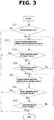
- FIG. 3 is a flow chart showing a flow of control of wastegate valve 23 and variable nozzle 13 when the intake air quantity is to be increased along with an increase in the engine load.
- the control of FIG. 3 is performed by control unit 16.
- control unit 16 determines whether or not the accelerator is in on-state. In this example, control unit 16 determines that the accelerator is in on-state, in response to a condition that a driver depresses the accelerator pedal. When determining that the accelerator is in on-state, control unit 16 then proceeds to Step S13. On the other hand, when determining that the accelerator is not in on-state, control unit 16 then terminates the present routine.
- control unit 16 performs the valve opening reducing operation of wastegate valve 23 so as to increase the intake air quantity, and thereby conform the boost pressure to the target boost pressure.
- control unit 16 determines whether or not the intake air pressure downstream of compressor 11 (i.e. the boost pressure) has risen up to the target boost pressure. When determining that the boost pressure is lower than the target boost pressure, control unit 16 then proceeds from Step S13 to Step S14. When determining that the boost pressure has become equal to the target boost pressure, control unit 16 then terminates the valve opening reducing operation of wastegate valve 23 (thereby maintains the valve opening of wastegate valve 23 at the current state), and terminates the present routine.
- control unit 16 determines whether or not wastegate valve 23 is in fully closed state. When determining that wastegate valve 23 is not in fully closed state, control unit 16 then proceeds to Step S12, and continues the valve opening reducing operation of wastegate valve 23. When determining that wastegate valve 23 is in fully closed state, control unit 16 then proceeds to Step S15.
- the valve opening of wastegate valve 23 may be identified by sensing with a sensor provided, or by estimation from pressures of the upstream and downstream sides of wastegate valve 23.
- control unit 16 performs the valve opening reducing operation of wastegate valve 23 so as to increase the intake air quantity, and thereby conform the boost pressure to the target boost pressure.
- the nozzle opening reducing operation of variable nozzle 13 is carried out in case the boost pressure does not reach the target boost pressure even when wastegate valve 23 is in fully closed state.
- control unit 16 determines whether or not the intake air pressure downstream of compressor 11 (i.e. the boost pressure) has risen up to the target boost pressure. When determining that the boost pressure is lower than the target boost pressure, control unit 16 then proceeds from Step S16 to Step S17. When determining that the boost pressure has become equal to the target boost pressure, control unit 16 then terminates the nozzle opening reducing operation of variable nozzle 13 (thereby maintains the nozzle opening of variable nozzle 13 at the current state), and terminates the present routine.
- the boost pressure i.e. the boost pressure
- control unit 16 determines whether or not the nozzle opening of variable nozzle 13 is minimized (in fully closed state). When determining that the nozzle opening of variable nozzle 13 is not minimized (in fully closed state), control unit 16 then proceeds to Step S15, and continues the nozzle opening reducing operation of variable nozzle 13. When determining that the nozzle opening of variable nozzle 13 is minimized (in fully closed state), control unit 16 then terminates the present routine.
- the nozzle opening of variable nozzle 13 may be identified by sensing with a sensor provided, or by estimation from the pressures of the upstream and downstream sides of exhaust turbine 12.
- wastegate valve 23 When wastegate valve 23 is in closed state, thermal energy can be efficiently recovered as a work of the boost pressure than when wastegate valve 23 is in opened state. This is because even if the nozzle opening of variable nozzle 13 is reduced in order to raise pressure energy when wastegate valve 23 is in opened state, pressure is relieved via the wastegate valve 23.
- the feature of operating the wastegate valve 23 with higher priority to variable nozzle 13 of turbocharger 10 when the intake air quantity is to be increased due to an increase in the engine load serves to reduce the pumping loss, and thereby enhance the fuel efficiency of internal combustion engine 1.
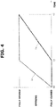
- FIG. 4 is a timing chart showing an example of operation of wastegate valve 23 and variable nozzle 13 when the intake air quantity is to be reduced along with a decrease in the engine load.
- a solid line represents a characteristic line Lw of the valve opening of wastegate valve 23
- a broken line represents a characteristic line Ln of the nozzle opening of variable nozzle 13.
- variable nozzle 13 When the engine load falls, and the target boost pressure falls, and the intake air quantity is to be reduced, a nozzle opening increasing operation of variable nozzle 13 is performed with higher priority to a valve opening increasing operation of wastegate valve 23.
- the engine load starts to fall, and the target boost pressure starts to fall, and the intake air quantity of internal combustion engine 1 starts to be reduced.
- the nozzle opening increasing operation of variable nozzle 13 is started.
- the valve opening increasing operation of wastegate valve 23 is started. The valve opening increasing operation of wastegate valve 23 is carried out in case the boost pressure is higher than the target boost pressure even when variable nozzle 13 is in fully opened state.
- both of the valve opening of wastegate valve 23 and the nozzle opening of variable nozzle 13 are minimized (in fully closed state).
- the boost pressure becomes equal to the target boost pressure, and the valve opening of wastegate valve 23 is fully opened.
- the valve opening increasing operation of wastegate valve 23 is an operation to change the valve opening of wastegate valve 23 in an opening direction from a current state.
- the nozzle opening increasing operation of variable nozzle 13 is an operation to change the nozzle opening of variable nozzle 13 in an increasing direction from a current state.
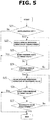
- FIG. 5 is a flow chart showing a flow of control of wastegate valve 23 and variable nozzle 13 when the intake air quantity is to be reduced along with a decrease in the engine load.
- the control of FIG. 5 is performed by control unit 16.
- control unit 16 determines whether or not the accelerator is in off-state. In this example, control unit 16 determines that the accelerator is in off-state, in response to a condition that a driver releases the accelerator pedal. When determining that the accelerator is in off-state, control unit 16 then proceeds to Step S22. On the other hand, when determining that the accelerator is not in off-state, control unit 16 then terminates the present routine.
- control unit 16 performs the nozzle opening increasing operation of variable nozzle 13 so as to reduce the intake air quantity, and thereby conform the boost pressure to the target boost pressure.
- control unit 16 determines whether or not the intake air pressure downstream of compressor 11 (i.e. the boost pressure) has fallen down to the target boost pressure. When determining that the boost pressure is higher than the target boost pressure, control unit 16 then proceeds from Step S23 to Step S24. When determining that the boost pressure has become equal to the target boost pressure, control unit 16 then terminates the nozzle opening increasing operation of variable nozzle 13 (thereby maintains the nozzle opening of variable nozzle 13 at the current state), and terminates the present routine.
- control unit 16 determines whether or not the nozzle opening of variable nozzle 13 is maximized (in fully opened state). When determining that the nozzle opening of variable nozzle 13 is not maximized (in fully opened state), control unit 16 then proceeds to Step S22, and continues the nozzle opening increasing operation of variable nozzle 13. When determining that the nozzle opening of variable nozzle 13 is maximized (in fully opened state), control unit 16 then proceeds to Step S25.
- control unit 16 performs the valve opening increasing operation of wastegate valve 23 so as to reduce the intake air quantity, and thereby conform the boost pressure to the target boost pressure.
- the valve opening increasing operation of wastegate valve 23 is carried out in case the boost pressure does not reach the target boost pressure even when the nozzle opening of variable nozzle 13 is maximized (in fully opened state).
- control unit 16 determines whether or not the intake air pressure downstream of compressor 11 (i.e. the boost pressure) has reached the target boost pressure. When determining that the boost pressure is higher than the target boost pressure, control unit 16 then proceeds from Step S26 to Step S27. When determining that the boost pressure has become equal to the target boost pressure, control unit 16 then terminates the valve opening increasing operation of wastegate valve 23 (thereby maintains the valve opening of wastegate valve 23 at the current state), and terminates the present routine.
- control unit 16 determines whether or not wastegate valve 23 is in fully opened state. When determining that wastegate valve 23 is not in fully opened state, control unit 16 then proceeds to Step S25, and continues the valve opening increasing operation of wastegate valve 23. When determining that wastegate valve 23 is in fully opened state, control unit 16 then terminates the present routine.
- variable nozzle 13 When the nozzle opening of variable nozzle 13 is reduced to some extent, thermal energy cannot be recovered efficiently as a work of the boost pressure.
- variable nozzle 13 of turbocharger 10 serves to reduce the pumping loss, and thereby enhance the fuel efficiency of internal combustion engine 1.
- FIG. 6 is a timing chart showing an example of operation of wastegate valve 23 and variable nozzle 13 when the intake air quantity is to be increased so as to set the air fuel ratio leaner.
- a solid line represents a characteristic line Lw of the valve opening of wastegate valve 23
- a broken line represents a characteristic line Ln of the nozzle opening of variable nozzle 13.
- valve opening reducing operation of wastegate valve 23 is performed with higher priority to the nozzle opening reducing operation of variable nozzle 13.
- a target air fuel ratio starts to become leaner, and the intake air quantity of internal combustion engine 1 starts to be increased.
- the valve opening reducing operation of wastegate valve 23 is started.
- the nozzle opening reducing operation of variable nozzle 13 is started.
- the nozzle opening reducing operation of variable nozzle 13 is carried out in case the air fuel ratio does not reach the target air fuel ratio even when wastegate valve 23 is in fully closed state.
- the air fuel ratio is estimated from a sensed value acquired by air fuel ratio sensor 30 in this example.
- the target air fuel ratio is set depending on the operating state of internal combustion engine 1 in this example.
- both of the valve opening of wastegate valve 23 and the nozzle opening of variable nozzle 13 are maximized (in fully opened state).
- the air fuel ratio becomes equal to the target air fuel ratio, and the nozzle opening of variable nozzle 13 is minimized (in fully closed state).
- FIG. 7 is a flow chart showing a flow of control of wastegate valve 23 and variable nozzle 13 when the intake air quantity is to be increased so as to set the air fuel ratio leaner.
- the control of FIG. 7 is performed by control unit 16.
- control unit 16 determines whether or not the target air fuel ratio is varied to be leaner. When determining that the target air fuel ratio is varied to be leaner, control unit 16 then proceeds to Step S32. On the other hand, when determining that the target air fuel ratio is not varied to be leaner, control unit 16 then terminates the present routine.
- control unit 16 performs the valve opening reducing operation of wastegate valve 23 so as to increase the intake air quantity, and thereby conform the air fuel ratio to the target air fuel ratio.
- control unit 16 determines whether or not the air fuel ratio has reached the target air fuel ratio. In other words, control unit 16 determines whether or not an excess air ratio has reached a target value. When determining that the air fuel ratio has not reached the target air fuel ratio, control unit 16 then proceeds from Step S33 to Step S34. Namely, when determining that the excess air ratio has not reached the target value, control unit 16 then proceeds from Step S33 to Step S34.
- the excess air ratio is estimated from a sensed value acquired by air fuel ratio sensor 30 in this example. When determining that the air fuel ratio has reached the target air fuel ratio, control unit 16 then terminates the valve opening reducing operation of wastegate valve 23 (thereby maintains the valve opening of wastegate valve 23 at the current state), and terminates the present routine.
- control unit 16 determines whether or not wastegate valve 23 is in fully closed state. When determining that wastegate valve 23 is not in fully closed state, control unit 16 then proceeds to Step S32, and continues the valve opening reducing operation of wastegate valve 23. When determining that wastegate valve 23 is in fully closed state, control unit 16 then proceeds to Step S35.
- the valve opening of wastegate valve 23 may be identified by sensing with a sensor provided, or by estimation from pressures of the upstream and downstream sides of wastegate valve 23.
- control unit 16 performs the valve opening reducing operation of wastegate valve 23 so as to increase the intake air quantity, and thereby conform the air fuel ratio to the target air fuel ratio.
- the nozzle opening reducing operation of variable nozzle 13 is carried out in case the air fuel ratio does not reach the target air fuel ratio even when wastegate valve 23 is in fully closed state.
- control unit 16 determines whether or not the air fuel ratio has reached the target air fuel ratio. When determining that the air fuel ratio has not reached the target air fuel ratio, control unit 16 then proceeds from Step S36 to Step S37. Namely, when determining that the excess air ratio has not reached the target value, control unit 16 then proceeds from Step S36 to Step S37. When determining that the air fuel ratio has reached the target air fuel ratio, control unit 16 then terminates the nozzle opening reducing operation of variable nozzle 13 (thereby maintains the nozzle opening of variable nozzle 13 at the current state), and terminates the present routine.
- control unit 16 determines whether or not the nozzle opening of variable nozzle 13 is minimized (in fully closed state). When determining that the nozzle opening of variable nozzle 13 is not minimized (in fully closed state), control unit 16 then proceeds to Step S35, and continues the nozzle opening reducing operation of variable nozzle 13. When determining that the nozzle opening of variable nozzle 13 is minimized (in fully closed state), control unit 16 then terminates the present routine.
- the nozzle opening of variable nozzle 13 may be identified by sensing with a sensor provided, or by estimation from the pressures of the upstream and downstream sides of exhaust turbine 12.
- wastegate valve 23 When wastegate valve 23 is in closed state, thermal energy can be efficiently recovered as a work of the air fuel ratio than when wastegate valve 23 is in opened state. This is because even if the nozzle opening of variable nozzle 13 is reduced in order to raise pressure energy when wastegate valve 23 is in opened state, pressure is relieved via the wastegate valve 23.
- the feature of operating the wastegate valve 23 with higher priority to variable nozzle 13 of turbocharger 10 when the intake air quantity is to be increased so as to set the air fuel ratio leaner serves to reduce the pumping loss, and thereby enhance the fuel efficiency of internal combustion engine 1.
- FIG. 8 is a timing chart showing an example of operation of wastegate valve 23 and variable nozzle 13 when the intake air quantity is to be reduced so as to set the air fuel ratio richer.
- a solid line represents a characteristic line Lw of the valve opening of wastegate valve 23
- a broken line represents a characteristic line Ln of the nozzle opening of variable nozzle 13.
- variable nozzle 13 When the operating state of internal combustion engine 1 varies and the intake air quantity is to be reduced so as to set the air fuel ratio richer, the nozzle opening increasing operation of variable nozzle 13 is performed with higher priority to the valve opening increasing operation of wastegate valve 23.
- the target air fuel ratio starts to become richer, and the intake air quantity of internal combustion engine 1 starts to be reduced.
- the nozzle opening increasing operation of variable nozzle 13 is started.
- the valve opening increasing operation of wastegate valve 23 is started. The valve opening increasing operation of wastegate valve 23 is carried out in case the air fuel ratio does not reach the target air fuel ratio even when the nozzle opening of variable nozzle 13 is maximized (in fully opened state).
- both of the valve opening of wastegate valve 23 and the nozzle opening of variable nozzle 13 are minimized (in fully closed state).
- the air fuel ratio becomes equal to the target air fuel ratio, and the valve opening of wastegate valve 23 is in fully opened state.
- FIG. 9 is a flow chart showing a flow of control of wastegate valve 23 and variable nozzle 13 when the intake air quantity is to be reduced so as to set the air fuel ratio richer.
- the control of FIG. 9 is performed by control unit 16.
- control unit 16 determines whether or not the target air fuel ratio is varied to be richer. When determining that the target air fuel ratio is varied to be richer, control unit 16 then proceeds to Step S42. On the other hand, when determining that the target air fuel ratio is not varied to be richer, control unit 16 then terminates the present routine.
- control unit 16 performs the nozzle opening increasing operation of variable nozzle 13 so as to reduce the intake air quantity, and thereby conform the air fuel ratio to the target air fuel ratio.
- control unit 16 determines whether or not the air fuel ratio has reached the target air fuel ratio. When determining that the air fuel ratio has not reached the target air fuel ratio, control unit 16 then proceeds from Step S43 to Step S44. Namely, when determining that the excess air ratio has not reached the target value, control unit 16 then proceeds from Step S43 to Step S44. When determining that the air fuel ratio has reached the target air fuel ratio, control unit 16 then terminates the nozzle opening increasing operation of variable nozzle 13 (thereby maintains the nozzle opening of variable nozzle 13 at the current state), and terminates the present routine.
- control unit 16 determines whether or not the nozzle opening of variable nozzle 13 is maximized (in fully opened state). When determining that the nozzle opening of variable nozzle 13 is not maximized (in fully opened state), control unit 16 then proceeds to Step S42, and continues the nozzle opening increasing operation of variable nozzle 13. When determining that the nozzle opening of variable nozzle 13 is maximized (in fully opened state), control unit 16 then proceeds to Step S45.
- control unit 16 performs the valve opening increasing operation of wastegate valve 23 so as to reduce the intake air quantity, and thereby conform the air fuel ratio to the target air fuel ratio. In this way, the valve opening increasing operation of wastegate valve 23 is carried out in case the air fuel ratio does not reach the target air fuel ratio even when the nozzle opening of variable nozzle 13 is maximized (in fully opened state).
- control unit 16 determines whether or not the air fuel ratio has reached the target air fuel ratio. When determining that the air fuel ratio has not reached the target air fuel ratio, control unit 16 then proceeds from Step S46 to Step S47. Namely, when determining that the excess air ratio has not reached the target value, control unit 16 then proceeds from Step S46 to Step S47. When determining that the air fuel ratio has reached the target air fuel ratio, control unit 16 then terminates the valve opening increasing operation of wastegate valve 23 (thereby maintains the valve opening of wastegate valve 23 at the current state), and terminates the present routine.
- control unit 16 determines whether or not wastegate valve 23 is in fully opened state. When determining that wastegate valve 23 is not in fully opened state, control unit 16 then proceeds to Step S45, and continues the valve opening increasing operation of wastegate valve 23. When determining that wastegate valve 23 is in fully opened state, control unit 16 then terminates the present routine.
- variable nozzle 13 When the nozzle opening of variable nozzle 13 is reduced to some extent, thermal energy cannot be recovered efficiently as a work of the boost pressure.
- variable nozzle 13 of turbocharger 10 serves to reduce the pumping loss, and thereby enhance the fuel efficiency of internal combustion engine 1.
- variable nozzle 13 The configuration according to the present embodiment that the quantity of exhaust gas brought into exhaust turbine 12 can be adjusted by variable nozzle 13, may be modified such that the exhaust adjustment mechanism is not implemented by variable nozzle 13 but implemented by providing a flow rate control valve structured to vary a cross-sectional area of a path upstream of exhaust turbine 12 (flow path cross-sectional area).
Landscapes
- Engineering & Computer Science (AREA)
- Chemical & Material Sciences (AREA)
- Combustion & Propulsion (AREA)
- Mechanical Engineering (AREA)
- General Engineering & Computer Science (AREA)
- Supercharger (AREA)
- Output Control And Ontrol Of Special Type Engine (AREA)
Abstract
Description
- The present invention relates to an internal combustion engine control method and an internal combustion engine control device for an internal combustion engine provided with a turbocharger.
- A patent document 1 discloses an internal combustion engine provided with a turbocharger and a wastegate valve, wherein the turbocharger is a variable nozzle type turbocharger structured to adjust a state of boost by adjusting a vane angle (or nozzle opening) of an exhaust turbine, and wherein the wastegate valve is structured to allow a part of exhaust gas to bypass the exhaust turbine of the turbocharger and flow into a downstream side of the exhaust turbine, wherein the exhaust gas is to be brought into the exhaust turbine.
- Patent document 1 discloses controlling the nozzle opening of the exhaust turbine and a valve opening of the wastegate valve when in a transient state.
- However, no sufficient study has been made on efficient control of the wastegate valve and the nozzle opening of the exhaust turbine when in a transient state where an intake air quantity of the internal combustion engine is to be varied. Therefore, there is room for further improvement.
- Patent Document 1: Japanese Patent Application Publication No.
2007-303330 - According to the present invention, an internal combustion engine control method for an internal combustion engine, the internal combustion engine including: a turbocharger including an exhaust turbine; a wastegate valve structured to allow a part of exhaust gas to bypass the exhaust turbine and flow into a downstream side of the exhaust turbine, wherein the exhaust gas is to be brought into the exhaust turbine; and an exhaust adjustment mechanism structured to adjust a quantity of the exhaust gas; the internal combustion engine control method comprises: operating a first one of the wastegate valve and the exhaust adjustment mechanism with higher priority to a second one of the wastegate valve and the exhaust adjustment mechanism in response to a condition where an intake air quantity is to be varied, wherein operation of the first one allows thermal energy to be recovered more efficiently under the condition than that of the second one.
- The present invention makes it possible to recover thermal energy efficiently as a work of boost pressure. This serves to reduce a pumping loss, and thereby enhance fuel efficiency of the internal combustion engine.
-
-
FIG. 1 is an illustrative view schematically showing a general configuration of an internal combustion engine control device according to the present invention. -
FIG. 2 is a timing chart showing an example of operation of a wastegate valve and a variable nozzle when an intake air quantity is to be increased along with an increase in engine load. -
FIG. 3 is a flow chart showing a flow of control of the wastegate valve and the variable nozzle when the intake air quantity is to be increased along with an increase in engine load. -
FIG. 4 is a timing chart showing an example of operation of the wastegate valve and the variable nozzle when the intake air quantity is to be reduced along with a decrease in engine load. -
FIG. 5 is a flow chart showing a flow of control of the wastegate valve and the variable nozzle when the intake air quantity is to be reduced along with a decrease in engine load. -
FIG. 6 is a timing chart showing an example of operation of the wastegate valve and the variable nozzle when the intake air quantity is to be increased so as to set an air fuel ratio leaner. -
FIG. 7 is a flow chart showing a flow of control of the wastegate valve and the variable nozzle when the intake air quantity is to be increased so as to set the air fuel ratio leaner. -
FIG. 8 is a timing chart showing an example of operation of the wastegate valve and the variable nozzle when the intake air quantity is to be reduced so as to set the air fuel ratio richer. -
FIG. 9 is a flow chart showing a flow of control of the wastegate valve and the variable nozzle when the intake air quantity is to be reduced so as to set the air fuel ratio richer. - The following describes an embodiment of the present invention in detail with reference to the drawings.
-
FIG. 1 is an illustrative view schematically showing a general configuration of a control device for an internal combustion engine 1 according to the present invention, to which a control method for internal combustion engine 1 according to the present invention can be applied. - Internal combustion engine 1 has an in-cylinder direct injection configuration in this example, wherein each cylinder is provided with a fuel injection valve not shown for injecting fuel into the cylinder.
- Internal combustion engine 1 is mounted as a drive source on a vehicle such as an automotive vehicle, and is provided with an
intake passage 2 and anexhaust passage 3. - Internal combustion engine 1 is connected to
intake passage 2 in which an air cleaner 4, anair flow meter 5, and athrottle valve 6 are provided, wherein air cleaner 4 is structured to collect foreign matter contained in intake air, whereinair flow meter 5 is structured to sense an intake air quantity, and whereinthrottle valve 6 is an electronic throttle valve structured to adjust the intake air quantity.Air flow meter 5 is arranged upstream ofthrottle valve 6.Air flow meter 5 includes a temperature sensor inside, and is structured to sense a temperature of intake air at an intake inlet. Air cleaner 4 is arranged upstream ofair flow meter 5.Intake passage 2 is placed in an engine room in which internal combustion engine 1 is mounted. - Internal combustion engine 1 is connected to
exhaust passage 3 in which anupstream exhaust catalyst 7, adownstream exhaust catalyst 8, and amuffler 9 are provided, wherein upstreamexhaust catalyst 7 is a three-way catalyst or the like, whereindownstream exhaust catalyst 8 is a NOx trap catalyst or the like, and whereinmuffler 9 is structured to reduce an exhaust sound.Downstream exhaust catalyst 8 is arranged downstream ofupstream exhaust catalyst 7. Muffler 9 is arranged downstream ofdownstream exhaust catalyst 8. - Internal combustion engine 1 is further provided with a
turbocharger 10 including acompressor 11 and anexhaust turbine 12, whereincompressor 11 andexhaust turbine 12 are arranged coaxially, whereincompressor 11 is disposed inintake passage 2, andexhaust turbine 12 is disposed inexhaust passage 3.Compressor 11 is arranged upstream ofthrottle valve 6 and downstream ofair flow meter 5.Exhaust turbine 12 is arranged upstream ofupstream exhaust catalyst 7. Turbocharger 10 is a variable capacity type turbocharger including avariable nozzle 13 structured to adjust a capacity ofturbocharger 10. Specifically, whenvariable nozzle 13 is set to have a small nozzle opening,variable nozzle 13 has characteristics of small capacity suitable for a condition such as a low speed region where a flow rate of exhaust gas is low. Whenvariable nozzle 13 is set to have a large nozzle opening,variable nozzle 13 has characteristics of large capacity suitable for a condition such as a high speed region where the flow rate of exhaust gas is high.Variable nozzle 13 is structured to be driven by anactuator 14 of a diaphragm type that operates in response to a control pressure (or control negative pressure). The control pressure is generated via apressure control valve 15 that is controlled by duty control. -
Pressure control valve 15 is controlled by acontrol unit 16 as a control section. Namely,variable nozzle 13 ofturbocharger 10 is controlled bycontrol unit 16.Variable nozzle 13 is an exhaust adjustment mechanism structured to adjust a quantity of exhaust gas that is to be brought intoexhaust turbine 12 ofturbocharger 10, and thereby control a boost pressure of internal combustion engine 1. -
Control unit 16 is a well-known digital computer that includes a CPU, a ROM, a RAM, and an input and output interface. - In
intake passage 2, anintercooler 17 is provided downstream ofthrottle valve 6, whereinintercooler 17 is structured to cool intake air compressed (or pressurized) bycompressor 11, and thereby enhance efficiency of charging of intake air. -
Intercooler 17 is arranged in an intercooler cooling path (or auxiliary cooling path) 20 as well as a radiator (or intercooler radiator) 18 and anelectric pump 19. Intercooler 17 is structured to be supplied with a coolant (cooling water) cooled byradiator 18. -
Intercooler cooling path 20 is structured to allow the coolant to circulate therein.Intercooler cooling path 20 is independent from a main cooling path not shown where cooling water circulates for cooling acylinder block 21 of internal combustion engine 1. -
Radiator 18 is structured to cool the coolant inintercooler cooling path 20 by heat exchange with outside air. -
Electric pump 19 is structured to be driven to allow the coolant to circulate along an arrow A betweenradiator 18 andintercooler 17. -
Exhaust passage 3 is connected to anexhaust bypass passage 22 that bypasses theexhaust turbine 12 and connects an upstream side ofexhaust turbine 12 to a downstream side ofexhaust turbine 12.Exhaust bypass passage 22 has a downstream end connected to a portion ofexhaust passage 3 upstream ofupstream exhaust catalyst 7. Awastegate valve 23 of an electronic type is placed inexhaust bypass passage 22, and structured to control a flow rate of exhaust gas inexhaust bypass passage 22.Wastegate valve 23 is structured to bypass a part of exhaust gas, which is to be brought intoexhaust turbine 12, to the downstream side ofexhaust turbine 12, and thereby control the boost pressure of internal combustion engine 1.Wastegate valve 23 has a valve opening controlled bycontrol unit 16. - Internal combustion engine 1 includes an
EGR passage 24 branched fromexhaust passage 3 and connected tointake passage 2, and is structured to perform exhaust gas recirculation (EGR) to bring (recirculate) a part of exhaust gas as an EGR gas fromexhaust passage 3 intointake passage 2. EGRpassage 24 has a first end connected to a portion ofexhaust passage 3 betweenupstream exhaust catalyst 7 anddownstream exhaust catalyst 8, and a second end connected to a portion ofintake passage 2 downstream ofair flow meter 5 and upstream ofcompressor 11. In EGRpassage 24, anEGR valve 25 and anEGR cooler 26 are provided, whereinEGR valve 25 is of an electronic type and is structured to control the flow rate of EGR gas inEGR passage 24, and whereinEGR cooler 26 is structured to cool the EGR gas. EGRvalve 25 is controlled bycontrol unit 16 to open and close. -
Control unit 16 is configured to receive input of sensing signals from sensors, i.e.air flow meter 5, acrank angle sensor 27 for sensing a crank angle of a crankshaft not shown, anaccelerator opening sensor 28 for sensing a quantity of depression of an accelerator pedal not shown, aboost pressure sensor 29 for sensing an intake air pressure downstream of compressor 11 (i.e. boost pressure), an airfuel ratio sensor 30 for sensing an exhaust air fuel ratio upstream ofupstream exhaust catalyst 7, and anoxygen sensor 31 for sensing an exhaust air fuel ratio downstream ofupstream exhaust catalyst 7. - Crank
angle sensor 27 is structured to sense an engine speed of internal combustion engine 1. - Air
fuel ratio sensor 30 is a wide range type air fuel ratio sensor having a linear characteristic of output in proportion to the exhaust air fuel ratio.Oxygen sensor 31 is a sensor structured to sense simply whether the air fuel ratio is rich or lean, wherein its output voltage varies in an on-off manner in a narrow range in vicinity of a theoretical air fuel ratio. - In response to a condition where an operating state of internal combustion engine 1 varies and the intake air quantity of internal combustion engine 1 is to be varied, a valve opening of
throttle valve 6 is controlled and one ofwastegate valve 23 andvariable nozzle 13, which allows thermal energy to be recovered efficiently as a work of boost pressure under this condition, is operated with higher priority to the other. This serves to reduce a pumping loss, and thereby enhance fuel efficiency of the internal combustion engine. -
FIG. 2 is a timing chart showing an example of operation ofwastegate valve 23 andvariable nozzle 13 when the intake air quantity is to be increased along with an increase in engine load (in load of internal combustion engine 1). InFIG. 2 , a solid line represents a characteristic line Lw of the valve opening ofwastegate valve 23, and a broken line represents a characteristic line Ln of the nozzle opening ofvariable nozzle 13. - When the engine load rises, and a target boost pressure rises, and the intake air quantity is to be increased, a valve opening reducing operation of
wastegate valve 23 is performed with higher priority to a nozzle opening reducing operation ofvariable nozzle 13. The target boost pressure is set depending on the operating state of internal combustion engine 1 in this example. - Specifically, in the example of
FIG. 2 , at a time instant t0, the engine load starts to rise, and the target boost pressure starts to rise, and the intake air quantity of internal combustion engine 1 starts to be increased. Accordingly, inFIG. 2 , at time instant t0, the valve opening reducing operation ofwastegate valve 23 is started. Thereafter, inFIG. 2 , at a time instant t1 whenwastegate valve 23 has been brought in fully closed state, the nozzle opening reducing operation ofvariable nozzle 13 is started. The nozzle opening reducing operation ofvariable nozzle 13 is carried out in case the boost pressure does not reach the target boost pressure even whenwastegate valve 23 is in fully closed state. - In
FIG. 2 , at time instant t0, the operating state shifts from a non-boost region into a boost region. For example, it is possible to determine whether internal combustion engine 1 is in the non-boost region or in the boost region, based on the engine load and the engine speed. InFIG. 2 , until time instant t0, both of the valve opening ofwastegate valve 23 and the nozzle opening ofvariable nozzle 13 are maximized (in fully opened state). InFIG. 2 , at a time instant t2, the boost pressure becomes equal to the target boost pressure, and the nozzle opening ofvariable nozzle 13 is minimized (in fully closed state). - The valve opening reducing operation of
wastegate valve 23 is an operation to change the valve opening ofwastegate valve 23 in a closing direction from a current state. The nozzle opening reducing operation ofvariable nozzle 13 is an operation to change the nozzle opening ofvariable nozzle 13 in a reducing direction from a current state. -
FIG. 3 is a flow chart showing a flow of control ofwastegate valve 23 andvariable nozzle 13 when the intake air quantity is to be increased along with an increase in the engine load. The control ofFIG. 3 is performed bycontrol unit 16. - At Step S11,
control unit 16 determines whether or not the accelerator is in on-state. In this example,control unit 16 determines that the accelerator is in on-state, in response to a condition that a driver depresses the accelerator pedal. When determining that the accelerator is in on-state,control unit 16 then proceeds to Step S13. On the other hand, when determining that the accelerator is not in on-state,control unit 16 then terminates the present routine. - At Step S12,
control unit 16 performs the valve opening reducing operation ofwastegate valve 23 so as to increase the intake air quantity, and thereby conform the boost pressure to the target boost pressure. - At Step S13,
control unit 16 determines whether or not the intake air pressure downstream of compressor 11 (i.e. the boost pressure) has risen up to the target boost pressure. When determining that the boost pressure is lower than the target boost pressure,control unit 16 then proceeds from Step S13 to Step S14. When determining that the boost pressure has become equal to the target boost pressure,control unit 16 then terminates the valve opening reducing operation of wastegate valve 23 (thereby maintains the valve opening ofwastegate valve 23 at the current state), and terminates the present routine. - At Step S14,
control unit 16 determines whether or notwastegate valve 23 is in fully closed state. When determining thatwastegate valve 23 is not in fully closed state,control unit 16 then proceeds to Step S12, and continues the valve opening reducing operation ofwastegate valve 23. When determining thatwastegate valve 23 is in fully closed state,control unit 16 then proceeds to Step S15. The valve opening ofwastegate valve 23 may be identified by sensing with a sensor provided, or by estimation from pressures of the upstream and downstream sides ofwastegate valve 23. - At Step S15,
control unit 16 performs the valve opening reducing operation ofwastegate valve 23 so as to increase the intake air quantity, and thereby conform the boost pressure to the target boost pressure. In this way, the nozzle opening reducing operation ofvariable nozzle 13 is carried out in case the boost pressure does not reach the target boost pressure even whenwastegate valve 23 is in fully closed state. - At Step S16,
control unit 16 determines whether or not the intake air pressure downstream of compressor 11 (i.e. the boost pressure) has risen up to the target boost pressure. When determining that the boost pressure is lower than the target boost pressure,control unit 16 then proceeds from Step S16 to Step S17. When determining that the boost pressure has become equal to the target boost pressure,control unit 16 then terminates the nozzle opening reducing operation of variable nozzle 13 (thereby maintains the nozzle opening ofvariable nozzle 13 at the current state), and terminates the present routine. - At Step S17,
control unit 16 determines whether or not the nozzle opening ofvariable nozzle 13 is minimized (in fully closed state). When determining that the nozzle opening ofvariable nozzle 13 is not minimized (in fully closed state),control unit 16 then proceeds to Step S15, and continues the nozzle opening reducing operation ofvariable nozzle 13. When determining that the nozzle opening ofvariable nozzle 13 is minimized (in fully closed state),control unit 16 then terminates the present routine. The nozzle opening ofvariable nozzle 13 may be identified by sensing with a sensor provided, or by estimation from the pressures of the upstream and downstream sides ofexhaust turbine 12. - When
wastegate valve 23 is in closed state, thermal energy can be efficiently recovered as a work of the boost pressure than whenwastegate valve 23 is in opened state. This is because even if the nozzle opening ofvariable nozzle 13 is reduced in order to raise pressure energy whenwastegate valve 23 is in opened state, pressure is relieved via thewastegate valve 23. - Accordingly, the feature of operating the
wastegate valve 23 with higher priority tovariable nozzle 13 ofturbocharger 10 when the intake air quantity is to be increased due to an increase in the engine load, serves to reduce the pumping loss, and thereby enhance the fuel efficiency of internal combustion engine 1. -
FIG. 4 is a timing chart showing an example of operation ofwastegate valve 23 andvariable nozzle 13 when the intake air quantity is to be reduced along with a decrease in the engine load. InFIG. 4 , a solid line represents a characteristic line Lw of the valve opening ofwastegate valve 23, and a broken line represents a characteristic line Ln of the nozzle opening ofvariable nozzle 13. - When the engine load falls, and the target boost pressure falls, and the intake air quantity is to be reduced, a nozzle opening increasing operation of
variable nozzle 13 is performed with higher priority to a valve opening increasing operation ofwastegate valve 23. - Specifically, in the example of
FIG. 4 , at a time instant t0, the engine load starts to fall, and the target boost pressure starts to fall, and the intake air quantity of internal combustion engine 1 starts to be reduced. Accordingly, inFIG. 4 , at time instant t0, the nozzle opening increasing operation ofvariable nozzle 13 is started. Thereafter, inFIG. 4 , at a time instant t1 when the nozzle opening ofvariable nozzle 13 is has been maximized (in in fully opened state), the valve opening increasing operation ofwastegate valve 23 is started. The valve opening increasing operation ofwastegate valve 23 is carried out in case the boost pressure is higher than the target boost pressure even whenvariable nozzle 13 is in fully opened state. - In
FIG. 4 , at time instant t0, both of the valve opening ofwastegate valve 23 and the nozzle opening ofvariable nozzle 13 are minimized (in fully closed state). InFIG. 4 , at a time instant t2, the boost pressure becomes equal to the target boost pressure, and the valve opening ofwastegate valve 23 is fully opened. - The valve opening increasing operation of
wastegate valve 23 is an operation to change the valve opening ofwastegate valve 23 in an opening direction from a current state. The nozzle opening increasing operation ofvariable nozzle 13 is an operation to change the nozzle opening ofvariable nozzle 13 in an increasing direction from a current state. -
FIG. 5 is a flow chart showing a flow of control ofwastegate valve 23 andvariable nozzle 13 when the intake air quantity is to be reduced along with a decrease in the engine load. The control ofFIG. 5 is performed bycontrol unit 16. - At Step S21,
control unit 16 determines whether or not the accelerator is in off-state. In this example,control unit 16 determines that the accelerator is in off-state, in response to a condition that a driver releases the accelerator pedal. When determining that the accelerator is in off-state,control unit 16 then proceeds to Step S22. On the other hand, when determining that the accelerator is not in off-state,control unit 16 then terminates the present routine. - At Step S22,
control unit 16 performs the nozzle opening increasing operation ofvariable nozzle 13 so as to reduce the intake air quantity, and thereby conform the boost pressure to the target boost pressure. - At Step S23,
control unit 16 determines whether or not the intake air pressure downstream of compressor 11 (i.e. the boost pressure) has fallen down to the target boost pressure. When determining that the boost pressure is higher than the target boost pressure,control unit 16 then proceeds from Step S23 to Step S24. When determining that the boost pressure has become equal to the target boost pressure,control unit 16 then terminates the nozzle opening increasing operation of variable nozzle 13 (thereby maintains the nozzle opening ofvariable nozzle 13 at the current state), and terminates the present routine. - At Step S24,
control unit 16 determines whether or not the nozzle opening ofvariable nozzle 13 is maximized (in fully opened state). When determining that the nozzle opening ofvariable nozzle 13 is not maximized (in fully opened state),control unit 16 then proceeds to Step S22, and continues the nozzle opening increasing operation ofvariable nozzle 13. When determining that the nozzle opening ofvariable nozzle 13 is maximized (in fully opened state),control unit 16 then proceeds to Step S25. - At Step S25,
control unit 16 performs the valve opening increasing operation ofwastegate valve 23 so as to reduce the intake air quantity, and thereby conform the boost pressure to the target boost pressure. In this way, the valve opening increasing operation ofwastegate valve 23 is carried out in case the boost pressure does not reach the target boost pressure even when the nozzle opening ofvariable nozzle 13 is maximized (in fully opened state). - At Step S26,
control unit 16 determines whether or not the intake air pressure downstream of compressor 11 (i.e. the boost pressure) has reached the target boost pressure. When determining that the boost pressure is higher than the target boost pressure,control unit 16 then proceeds from Step S26 to Step S27. When determining that the boost pressure has become equal to the target boost pressure,control unit 16 then terminates the valve opening increasing operation of wastegate valve 23 (thereby maintains the valve opening ofwastegate valve 23 at the current state), and terminates the present routine. - At Step S27,
control unit 16 determines whether or notwastegate valve 23 is in fully opened state. When determining thatwastegate valve 23 is not in fully opened state,control unit 16 then proceeds to Step S25, and continues the valve opening increasing operation ofwastegate valve 23. When determining thatwastegate valve 23 is in fully opened state,control unit 16 then terminates the present routine. - When the nozzle opening of
variable nozzle 13 is reduced to some extent, thermal energy cannot be recovered efficiently as a work of the boost pressure. - Accordingly, the feature of operating the
variable nozzle 13 ofturbocharger 10 with higher priority towastegate valve 23 when the intake air quantity is to be reduced due to a decrease in the engine load, serves to reduce the pumping loss, and thereby enhance the fuel efficiency of internal combustion engine 1. -
FIG. 6 is a timing chart showing an example of operation ofwastegate valve 23 andvariable nozzle 13 when the intake air quantity is to be increased so as to set the air fuel ratio leaner. InFIG. 6 , a solid line represents a characteristic line Lw of the valve opening ofwastegate valve 23, and a broken line represents a characteristic line Ln of the nozzle opening ofvariable nozzle 13. - When the operating state of internal combustion engine 1 varies and the intake air quantity is to be increased so as to set the air fuel ratio leaner, the valve opening reducing operation of
wastegate valve 23 is performed with higher priority to the nozzle opening reducing operation ofvariable nozzle 13. - Specifically, in the example of
FIG. 6 , at a time instant t0, a target air fuel ratio starts to become leaner, and the intake air quantity of internal combustion engine 1 starts to be increased. Accordingly, inFIG. 6 , at time instant t0, the valve opening reducing operation ofwastegate valve 23 is started. Thereafter, inFIG. 6 , at a time instant t1 whenwastegate valve 23 has been brought in fully closed state, the nozzle opening reducing operation ofvariable nozzle 13 is started. The nozzle opening reducing operation ofvariable nozzle 13 is carried out in case the air fuel ratio does not reach the target air fuel ratio even whenwastegate valve 23 is in fully closed state. The air fuel ratio is estimated from a sensed value acquired by airfuel ratio sensor 30 in this example. The target air fuel ratio is set depending on the operating state of internal combustion engine 1 in this example. - In
FIG. 6 , at time instant t0, both of the valve opening ofwastegate valve 23 and the nozzle opening ofvariable nozzle 13 are maximized (in fully opened state). InFIG. 6 , at a time instant t2, the air fuel ratio becomes equal to the target air fuel ratio, and the nozzle opening ofvariable nozzle 13 is minimized (in fully closed state). -
FIG. 7 is a flow chart showing a flow of control ofwastegate valve 23 andvariable nozzle 13 when the intake air quantity is to be increased so as to set the air fuel ratio leaner. The control ofFIG. 7 is performed bycontrol unit 16. - At Step S31,
control unit 16 determines whether or not the target air fuel ratio is varied to be leaner. When determining that the target air fuel ratio is varied to be leaner,control unit 16 then proceeds to Step S32. On the other hand, when determining that the target air fuel ratio is not varied to be leaner,control unit 16 then terminates the present routine. - At Step S32,
control unit 16 performs the valve opening reducing operation ofwastegate valve 23 so as to increase the intake air quantity, and thereby conform the air fuel ratio to the target air fuel ratio. - At Step S33,
control unit 16 determines whether or not the air fuel ratio has reached the target air fuel ratio. In other words,control unit 16 determines whether or not an excess air ratio has reached a target value. When determining that the air fuel ratio has not reached the target air fuel ratio,control unit 16 then proceeds from Step S33 to Step S34. Namely, when determining that the excess air ratio has not reached the target value,control unit 16 then proceeds from Step S33 to Step S34. The excess air ratio is estimated from a sensed value acquired by airfuel ratio sensor 30 in this example. When determining that the air fuel ratio has reached the target air fuel ratio,control unit 16 then terminates the valve opening reducing operation of wastegate valve 23 (thereby maintains the valve opening ofwastegate valve 23 at the current state), and terminates the present routine. - At Step S34,
control unit 16 determines whether or notwastegate valve 23 is in fully closed state. When determining thatwastegate valve 23 is not in fully closed state,control unit 16 then proceeds to Step S32, and continues the valve opening reducing operation ofwastegate valve 23. When determining thatwastegate valve 23 is in fully closed state,control unit 16 then proceeds to Step S35. The valve opening ofwastegate valve 23 may be identified by sensing with a sensor provided, or by estimation from pressures of the upstream and downstream sides ofwastegate valve 23. - At Step S35,
control unit 16 performs the valve opening reducing operation ofwastegate valve 23 so as to increase the intake air quantity, and thereby conform the air fuel ratio to the target air fuel ratio. In this way, the nozzle opening reducing operation ofvariable nozzle 13 is carried out in case the air fuel ratio does not reach the target air fuel ratio even whenwastegate valve 23 is in fully closed state. - At Step S36,
control unit 16 determines whether or not the air fuel ratio has reached the target air fuel ratio. When determining that the air fuel ratio has not reached the target air fuel ratio,control unit 16 then proceeds from Step S36 to Step S37. Namely, when determining that the excess air ratio has not reached the target value,control unit 16 then proceeds from Step S36 to Step S37. When determining that the air fuel ratio has reached the target air fuel ratio,control unit 16 then terminates the nozzle opening reducing operation of variable nozzle 13 (thereby maintains the nozzle opening ofvariable nozzle 13 at the current state), and terminates the present routine. - At Step S37,
control unit 16 determines whether or not the nozzle opening ofvariable nozzle 13 is minimized (in fully closed state). When determining that the nozzle opening ofvariable nozzle 13 is not minimized (in fully closed state),control unit 16 then proceeds to Step S35, and continues the nozzle opening reducing operation ofvariable nozzle 13. When determining that the nozzle opening ofvariable nozzle 13 is minimized (in fully closed state),control unit 16 then terminates the present routine. The nozzle opening ofvariable nozzle 13 may be identified by sensing with a sensor provided, or by estimation from the pressures of the upstream and downstream sides ofexhaust turbine 12. - When
wastegate valve 23 is in closed state, thermal energy can be efficiently recovered as a work of the air fuel ratio than whenwastegate valve 23 is in opened state. This is because even if the nozzle opening ofvariable nozzle 13 is reduced in order to raise pressure energy whenwastegate valve 23 is in opened state, pressure is relieved via thewastegate valve 23. - Accordingly, the feature of operating the
wastegate valve 23 with higher priority tovariable nozzle 13 ofturbocharger 10 when the intake air quantity is to be increased so as to set the air fuel ratio leaner, serves to reduce the pumping loss, and thereby enhance the fuel efficiency of internal combustion engine 1. -
FIG. 8 is a timing chart showing an example of operation ofwastegate valve 23 andvariable nozzle 13 when the intake air quantity is to be reduced so as to set the air fuel ratio richer. InFIG. 8 , a solid line represents a characteristic line Lw of the valve opening ofwastegate valve 23, and a broken line represents a characteristic line Ln of the nozzle opening ofvariable nozzle 13. - When the operating state of internal combustion engine 1 varies and the intake air quantity is to be reduced so as to set the air fuel ratio richer, the nozzle opening increasing operation of
variable nozzle 13 is performed with higher priority to the valve opening increasing operation ofwastegate valve 23. - Specifically, in the example of
FIG. 8 , at a time instant t0, the target air fuel ratio starts to become richer, and the intake air quantity of internal combustion engine 1 starts to be reduced. Accordingly, inFIG. 8 , at time instant t0, the nozzle opening increasing operation ofvariable nozzle 13 is started. Thereafter, inFIG. 8 , at a time instant t1 when the nozzle opening ofvariable nozzle 13 is has been maximized (in in fully opened state), the valve opening increasing operation ofwastegate valve 23 is started. The valve opening increasing operation ofwastegate valve 23 is carried out in case the air fuel ratio does not reach the target air fuel ratio even when the nozzle opening ofvariable nozzle 13 is maximized (in fully opened state). - In
FIG. 8 , at time instant t0, both of the valve opening ofwastegate valve 23 and the nozzle opening ofvariable nozzle 13 are minimized (in fully closed state). InFIG. 8 , at a time instant t2, the air fuel ratio becomes equal to the target air fuel ratio, and the valve opening ofwastegate valve 23 is in fully opened state. -
FIG. 9 is a flow chart showing a flow of control ofwastegate valve 23 andvariable nozzle 13 when the intake air quantity is to be reduced so as to set the air fuel ratio richer. The control ofFIG. 9 is performed bycontrol unit 16. - At Step S41,
control unit 16 determines whether or not the target air fuel ratio is varied to be richer. When determining that the target air fuel ratio is varied to be richer,control unit 16 then proceeds to Step S42. On the other hand, when determining that the target air fuel ratio is not varied to be richer,control unit 16 then terminates the present routine. - At Step S42,
control unit 16 performs the nozzle opening increasing operation ofvariable nozzle 13 so as to reduce the intake air quantity, and thereby conform the air fuel ratio to the target air fuel ratio. - At Step S43,
control unit 16 determines whether or not the air fuel ratio has reached the target air fuel ratio. When determining that the air fuel ratio has not reached the target air fuel ratio,control unit 16 then proceeds from Step S43 to Step S44. Namely, when determining that the excess air ratio has not reached the target value,control unit 16 then proceeds from Step S43 to Step S44. When determining that the air fuel ratio has reached the target air fuel ratio,control unit 16 then terminates the nozzle opening increasing operation of variable nozzle 13 (thereby maintains the nozzle opening ofvariable nozzle 13 at the current state), and terminates the present routine. - At Step S44,
control unit 16 determines whether or not the nozzle opening ofvariable nozzle 13 is maximized (in fully opened state). When determining that the nozzle opening ofvariable nozzle 13 is not maximized (in fully opened state),control unit 16 then proceeds to Step S42, and continues the nozzle opening increasing operation ofvariable nozzle 13. When determining that the nozzle opening ofvariable nozzle 13 is maximized (in fully opened state),control unit 16 then proceeds to Step S45. - At Step S45,
control unit 16 performs the valve opening increasing operation ofwastegate valve 23 so as to reduce the intake air quantity, and thereby conform the air fuel ratio to the target air fuel ratio. In this way, the valve opening increasing operation ofwastegate valve 23 is carried out in case the air fuel ratio does not reach the target air fuel ratio even when the nozzle opening ofvariable nozzle 13 is maximized (in fully opened state). - At Step S46,
control unit 16 determines whether or not the air fuel ratio has reached the target air fuel ratio. When determining that the air fuel ratio has not reached the target air fuel ratio,control unit 16 then proceeds from Step S46 to Step S47. Namely, when determining that the excess air ratio has not reached the target value,control unit 16 then proceeds from Step S46 to Step S47. When determining that the air fuel ratio has reached the target air fuel ratio,control unit 16 then terminates the valve opening increasing operation of wastegate valve 23 (thereby maintains the valve opening ofwastegate valve 23 at the current state), and terminates the present routine. - At Step S47,
control unit 16 determines whether or notwastegate valve 23 is in fully opened state. When determining thatwastegate valve 23 is not in fully opened state,control unit 16 then proceeds to Step S45, and continues the valve opening increasing operation ofwastegate valve 23. When determining thatwastegate valve 23 is in fully opened state,control unit 16 then terminates the present routine. - When the nozzle opening of
variable nozzle 13 is reduced to some extent, thermal energy cannot be recovered efficiently as a work of the boost pressure. - Accordingly, the feature of operating the
variable nozzle 13 ofturbocharger 10 with higher priority towastegate valve 23 when the intake air quantity is to be reduced so as to set the air fuel ratio richer, serves to reduce the pumping loss, and thereby enhance the fuel efficiency of internal combustion engine 1. - The configuration according to the present embodiment that the quantity of exhaust gas brought into
exhaust turbine 12 can be adjusted byvariable nozzle 13, may be modified such that the exhaust adjustment mechanism is not implemented byvariable nozzle 13 but implemented by providing a flow rate control valve structured to vary a cross-sectional area of a path upstream of exhaust turbine 12 (flow path cross-sectional area).
Claims (10)
- An internal combustion engine control method for an internal combustion engine,
the internal combustion engine including:a turbocharger including:a compressor disposed in an intake passage; andan exhaust turbine disposed in an exhaust passage;a wastegate valve structured to allow a part of exhaust gas to bypass the exhaust turbine and flow into a downstream side of the exhaust turbine, wherein the exhaust gas is to be brought into the exhaust turbine; andan exhaust adjustment mechanism structured to adjust a quantity of the exhaust gas;the internal combustion engine control method comprising:
operating a first one of the wastegate valve and the exhaust adjustment mechanism with higher priority to a second one of the wastegate valve and the exhaust adjustment mechanism in response to a condition where an intake air quantity is to be varied, wherein operation of the first one allows thermal energy to be recovered more efficiently under the condition than that of the second one. - The internal combustion engine control method as claimed in Claim 1, comprising:
performing a valve opening reducing operation of the wastegate valve with higher priority to operation of the exhaust adjustment mechanism, in response to a condition where the intake air quantity is to be increased along with an increase in engine load. - The internal combustion engine control method as claimed in Claim 2, comprising:
starting to perform an opening reducing operation of the exhaust adjustment mechanism after the wastegate valve is brought into fully-closed state in response to a condition where the intake air quantity is to be increased along with an increase in engine load. - The internal combustion engine control method as claimed in Claim 1, comprising:
performing an opening increasing operation of the exhaust adjustment mechanism with higher priority to operation of the wastegate valve, in response to a condition where the intake air quantity is to be reduced along with a decrease in engine load. - The internal combustion engine control method as claimed in Claim 4, comprising:
starting to perform a valve opening increasing operation of the wastegate valve after the exhaust adjustment mechanism is brought into fully-opened state in response to a condition where the intake air quantity is to be reduced along with a decrease in engine load. - The internal combustion engine control method as claimed in Claim 1, comprising:
performing a valve opening reducing operation of the wastegate valve with higher priority to operation of the exhaust adjustment mechanism, in response to a condition where the intake air quantity is to be increased so as to set an air fuel ratio learner. - The internal combustion engine control method as claimed in Claim 6, comprising:
starting to perform an opening reducing operation of the exhaust adjustment mechanism after the wastegate valve is brought into fully-closed state in response to a condition where the intake air quantity is to be increased so as to set the air fuel ratio learner. - The internal combustion engine control method as claimed in Claim 1, comprising:
performing an opening increasing operation of the exhaust adjustment mechanism with higher priority to operation of the wastegate valve, in response to a condition where the intake air quantity is to be reduced so as to set an air fuel ratio richer. - The internal combustion engine control method as claimed in Claim 8, comprising:
starting to perform a valve opening increasing operation of the wastegate valve after the exhaust adjustment mechanism is brought into fully-opened state in response to a condition where the intake air quantity is to be increased so as to set the air fuel ratio richer. - An internal combustion engine control device for an internal combustion engine,
the internal combustion engine including:a turbocharger including:a compressor disposed in an intake passage; andan exhaust turbine disposed in an exhaust passage;a wastegate valve structured to allow a part of exhaust gas to bypass the exhaust turbine and flow into a downstream side of the exhaust turbine, wherein the exhaust gas is to be brought into the exhaust turbine; andan exhaust adjustment mechanism structured to adjust a quantity of the exhaust gas;the internal combustion engine control device comprising:
a control section configured to operate a first one of the wastegate valve and the exhaust adjustment mechanism with higher priority to a second one of the wastegate valve and the exhaust adjustment mechanism in response to a condition where an intake air quantity is to be varied, wherein operation of the first one allows thermal energy to be recovered more efficiently under the condition than that of the second one.
Applications Claiming Priority (1)
| Application Number | Priority Date | Filing Date | Title |
|---|---|---|---|
| PCT/JP2017/015663 WO2018193532A1 (en) | 2017-04-19 | 2017-04-19 | Internal combustion engine control method and internal combustion engine control device |
Publications (3)
| Publication Number | Publication Date |
|---|---|
| EP3613963A1 true EP3613963A1 (en) | 2020-02-26 |
| EP3613963A4 EP3613963A4 (en) | 2020-05-06 |
| EP3613963B1 EP3613963B1 (en) | 2022-05-04 |
Family
ID=63856504
Family Applications (1)
| Application Number | Title | Priority Date | Filing Date |
|---|---|---|---|
| EP17905991.0A Active EP3613963B1 (en) | 2017-04-19 | 2017-04-19 | Internal combustion engine control method and internal combustion engine control device |
Country Status (5)
| Country | Link |
|---|---|
| US (1) | US10697360B2 (en) |
| EP (1) | EP3613963B1 (en) |
| JP (1) | JP6784325B2 (en) |
| CN (1) | CN110573710B (en) |
| WO (1) | WO2018193532A1 (en) |
Families Citing this family (1)
| Publication number | Priority date | Publication date | Assignee | Title |
|---|---|---|---|---|
| US11933234B2 (en) * | 2020-07-28 | 2024-03-19 | Nissan Motor Co., Ltd. | Supercharging pressure control method and supercharging pressure control device for internal combustion engine |
Family Cites Families (7)
| Publication number | Priority date | Publication date | Assignee | Title |
|---|---|---|---|---|
| JP2002054446A (en) | 2000-05-31 | 2002-02-20 | Aisin Seiki Co Ltd | Control device for variable turbocharger |
| US8112994B2 (en) * | 2005-10-12 | 2012-02-14 | Honeywell International Inc. | Method of controlling a turbocharger having a variable-geometry mechanism and a waste gate |
| JP4434174B2 (en) | 2006-05-10 | 2010-03-17 | 株式会社デンソー | Control device for an internal combustion engine with a supercharger |
| DE102007025077B4 (en) | 2007-05-30 | 2017-10-05 | Volkswagen Ag | Method for operating an internal combustion engine |
| US8209979B2 (en) * | 2009-03-24 | 2012-07-03 | GM Global Technology Operations LLC | Model-based control of airpath pressure limits by modulating a turbo charger by-pass valve and a variable-geometry turbine |
| US8397499B2 (en) * | 2009-08-24 | 2013-03-19 | Ford Global Technologies, Llc | Methods and systems for turbocharger control |
| JP6377340B2 (en) * | 2013-12-04 | 2018-08-22 | 三菱重工業株式会社 | Control device for supercharging system |
-
2017
- 2017-04-19 US US16/606,302 patent/US10697360B2/en active Active
- 2017-04-19 CN CN201780089832.7A patent/CN110573710B/en active Active
- 2017-04-19 JP JP2019513124A patent/JP6784325B2/en active Active
- 2017-04-19 WO PCT/JP2017/015663 patent/WO2018193532A1/en not_active Ceased
- 2017-04-19 EP EP17905991.0A patent/EP3613963B1/en active Active
Also Published As
| Publication number | Publication date |
|---|---|
| JPWO2018193532A1 (en) | 2020-01-09 |
| US20200131980A1 (en) | 2020-04-30 |
| EP3613963B1 (en) | 2022-05-04 |
| WO2018193532A1 (en) | 2018-10-25 |
| US10697360B2 (en) | 2020-06-30 |
| EP3613963A4 (en) | 2020-05-06 |
| JP6784325B2 (en) | 2020-11-11 |
| CN110573710A (en) | 2019-12-13 |
| CN110573710B (en) | 2021-01-01 |
Similar Documents
| Publication | Publication Date | Title |
|---|---|---|
| US10087822B2 (en) | Control apparatus for internal combustion engine | |
| JP4623064B2 (en) | Control device for an internal combustion engine with a supercharger | |
| US8096123B2 (en) | System and method for mode transition for a two-stage series sequential turbocharger | |
| CN101849091B (en) | Internal combustion engine controller | |
| CN101842565B (en) | With the internal combustion engine of exhaust-driven turbo-charger exhaust-gas turbo charger and charger-air cooler | |
| US9163555B2 (en) | Compressor bypass turbine-generator | |
| US10125727B2 (en) | Internal combustion engine | |
| US20090030589A1 (en) | Control apparatus of internal combustion engine and control method of internal combustion engine | |
| CN105026722A (en) | Control device for internal combustion engine | |
| US10344688B2 (en) | Apparatus and method for engine control | |
| CN111417772B (en) | Method and device for controlling internal combustion engine for vehicle | |
| JP2005009314A (en) | Supercharger for engine | |
| JP4412170B2 (en) | Supercharging system for internal combustion engines | |
| US10697360B2 (en) | Internal combustion engine control method and internal combustion engine control device | |
| JP6540659B2 (en) | Control system for internal combustion engine | |
| CN100476169C (en) | Internal combustion engine with supercharger | |
| JP6809448B2 (en) | Internal combustion engine control device | |
| KR102249597B1 (en) | Cotrol method for engine system | |
| JP2016138502A (en) | Cylinder deactivation control device for internal combustion engine | |
| JP2012097714A (en) | Control device for internal combustion engine with supercharger | |
| JPH08246963A (en) | Supercharged internal combustion engine with exhaust gas recirculation controller | |
| JP2017141734A (en) | Control device for internal combustion engine | |
| WO2026053279A1 (en) | Internal combustion engine control method and internal combustion engine control device | |
| JPH03279626A (en) | Supercharge pressure controller for two-cycle internal combustion engine | |
| JP2004225619A (en) | Internal combustion engine with exhaust turbocharger |
Legal Events
| Date | Code | Title | Description |
|---|---|---|---|
| STAA | Information on the status of an ep patent application or granted ep patent |
Free format text: STATUS: THE INTERNATIONAL PUBLICATION HAS BEEN MADE |
|
| PUAI | Public reference made under article 153(3) epc to a published international application that has entered the european phase |
Free format text: ORIGINAL CODE: 0009012 |
|
| STAA | Information on the status of an ep patent application or granted ep patent |
Free format text: STATUS: REQUEST FOR EXAMINATION WAS MADE |
|
| 17P | Request for examination filed |
Effective date: 20191028 |
|
| AK | Designated contracting states |
Kind code of ref document: A1 Designated state(s): AL AT BE BG CH CY CZ DE DK EE ES FI FR GB GR HR HU IE IS IT LI LT LU LV MC MK MT NL NO PL PT RO RS SE SI SK SM TR |
|
| AX | Request for extension of the european patent |
Extension state: BA ME |
|
| RAP1 | Party data changed (applicant data changed or rights of an application transferred) |
Owner name: RENAULT S.A.S. Owner name: NISSAN MOTOR CO., LTD. |
|
| A4 | Supplementary search report drawn up and despatched |
Effective date: 20200402 |
|
| RIC1 | Information provided on ipc code assigned before grant |
Ipc: F02B 37/24 20060101ALI20200328BHEP Ipc: F02D 41/00 20060101ALI20200328BHEP Ipc: F02B 37/18 20060101AFI20200328BHEP |
|
| DAV | Request for validation of the european patent (deleted) | ||
| DAX | Request for extension of the european patent (deleted) | ||
| STAA | Information on the status of an ep patent application or granted ep patent |
Free format text: STATUS: EXAMINATION IS IN PROGRESS |
|
| 17Q | First examination report despatched |
Effective date: 20201006 |
|
| GRAP | Despatch of communication of intention to grant a patent |
Free format text: ORIGINAL CODE: EPIDOSNIGR1 |
|
| STAA | Information on the status of an ep patent application or granted ep patent |
Free format text: STATUS: GRANT OF PATENT IS INTENDED |
|
| RIC1 | Information provided on ipc code assigned before grant |
Ipc: F02B 37/24 20060101ALI20220118BHEP Ipc: F02D 41/00 20060101ALI20220118BHEP Ipc: F02M 26/06 20160101ALI20220118BHEP Ipc: F02B 37/18 20060101AFI20220118BHEP |
|
| RAP3 | Party data changed (applicant data changed or rights of an application transferred) |
Owner name: RENAULT S.A.S Owner name: NISSAN MOTOR CO., LTD. |
|
| INTG | Intention to grant announced |
Effective date: 20220208 |
|
| GRAS | Grant fee paid |
Free format text: ORIGINAL CODE: EPIDOSNIGR3 |
|
| GRAA | (expected) grant |
Free format text: ORIGINAL CODE: 0009210 |
|
| STAA | Information on the status of an ep patent application or granted ep patent |
Free format text: STATUS: THE PATENT HAS BEEN GRANTED |
|
| RAP3 | Party data changed (applicant data changed or rights of an application transferred) |
Owner name: RENAULT S.A.S Owner name: NISSAN MOTOR CO., LTD. |
|
| AK | Designated contracting states |
Kind code of ref document: B1 Designated state(s): AL AT BE BG CH CY CZ DE DK EE ES FI FR GB GR HR HU IE IS IT LI LT LU LV MC MK MT NL NO PL PT RO RS SE SI SK SM TR |
|
| REG | Reference to a national code |
Ref country code: GB Ref legal event code: FG4D |
|
| REG | Reference to a national code |
Ref country code: CH Ref legal event code: EP |
|
| REG | Reference to a national code |
Ref country code: AT Ref legal event code: REF Ref document number: 1489253 Country of ref document: AT Kind code of ref document: T Effective date: 20220515 |
|
| REG | Reference to a national code |
Ref country code: IE Ref legal event code: FG4D Ref country code: DE Ref legal event code: R096 Ref document number: 602017057156 Country of ref document: DE |
|
| RAP4 | Party data changed (patent owner data changed or rights of a patent transferred) |
Owner name: RENAULT S.A.S Owner name: NISSAN MOTOR CO., LTD. |
|
| REG | Reference to a national code |
Ref country code: LT Ref legal event code: MG9D |
|
| REG | Reference to a national code |
Ref country code: NL Ref legal event code: MP Effective date: 20220504 |
|
| REG | Reference to a national code |
Ref country code: AT Ref legal event code: MK05 Ref document number: 1489253 Country of ref document: AT Kind code of ref document: T Effective date: 20220504 |
|
| PG25 | Lapsed in a contracting state [announced via postgrant information from national office to epo] |
Ref country code: SE Free format text: LAPSE BECAUSE OF FAILURE TO SUBMIT A TRANSLATION OF THE DESCRIPTION OR TO PAY THE FEE WITHIN THE PRESCRIBED TIME-LIMIT Effective date: 20220504 Ref country code: PT Free format text: LAPSE BECAUSE OF FAILURE TO SUBMIT A TRANSLATION OF THE DESCRIPTION OR TO PAY THE FEE WITHIN THE PRESCRIBED TIME-LIMIT Effective date: 20220905 Ref country code: NO Free format text: LAPSE BECAUSE OF FAILURE TO SUBMIT A TRANSLATION OF THE DESCRIPTION OR TO PAY THE FEE WITHIN THE PRESCRIBED TIME-LIMIT Effective date: 20220804 Ref country code: NL Free format text: LAPSE BECAUSE OF FAILURE TO SUBMIT A TRANSLATION OF THE DESCRIPTION OR TO PAY THE FEE WITHIN THE PRESCRIBED TIME-LIMIT Effective date: 20220504 Ref country code: LT Free format text: LAPSE BECAUSE OF FAILURE TO SUBMIT A TRANSLATION OF THE DESCRIPTION OR TO PAY THE FEE WITHIN THE PRESCRIBED TIME-LIMIT Effective date: 20220504 Ref country code: HR Free format text: LAPSE BECAUSE OF FAILURE TO SUBMIT A TRANSLATION OF THE DESCRIPTION OR TO PAY THE FEE WITHIN THE PRESCRIBED TIME-LIMIT Effective date: 20220504 Ref country code: GR Free format text: LAPSE BECAUSE OF FAILURE TO SUBMIT A TRANSLATION OF THE DESCRIPTION OR TO PAY THE FEE WITHIN THE PRESCRIBED TIME-LIMIT Effective date: 20220805 Ref country code: FI Free format text: LAPSE BECAUSE OF FAILURE TO SUBMIT A TRANSLATION OF THE DESCRIPTION OR TO PAY THE FEE WITHIN THE PRESCRIBED TIME-LIMIT Effective date: 20220504 Ref country code: ES Free format text: LAPSE BECAUSE OF FAILURE TO SUBMIT A TRANSLATION OF THE DESCRIPTION OR TO PAY THE FEE WITHIN THE PRESCRIBED TIME-LIMIT Effective date: 20220504 Ref country code: BG Free format text: LAPSE BECAUSE OF FAILURE TO SUBMIT A TRANSLATION OF THE DESCRIPTION OR TO PAY THE FEE WITHIN THE PRESCRIBED TIME-LIMIT Effective date: 20220804 Ref country code: AT Free format text: LAPSE BECAUSE OF FAILURE TO SUBMIT A TRANSLATION OF THE DESCRIPTION OR TO PAY THE FEE WITHIN THE PRESCRIBED TIME-LIMIT Effective date: 20220504 |
|
| PG25 | Lapsed in a contracting state [announced via postgrant information from national office to epo] |
Ref country code: RS Free format text: LAPSE BECAUSE OF FAILURE TO SUBMIT A TRANSLATION OF THE DESCRIPTION OR TO PAY THE FEE WITHIN THE PRESCRIBED TIME-LIMIT Effective date: 20220504 Ref country code: PL Free format text: LAPSE BECAUSE OF FAILURE TO SUBMIT A TRANSLATION OF THE DESCRIPTION OR TO PAY THE FEE WITHIN THE PRESCRIBED TIME-LIMIT Effective date: 20220504 Ref country code: LV Free format text: LAPSE BECAUSE OF FAILURE TO SUBMIT A TRANSLATION OF THE DESCRIPTION OR TO PAY THE FEE WITHIN THE PRESCRIBED TIME-LIMIT Effective date: 20220504 Ref country code: IS Free format text: LAPSE BECAUSE OF FAILURE TO SUBMIT A TRANSLATION OF THE DESCRIPTION OR TO PAY THE FEE WITHIN THE PRESCRIBED TIME-LIMIT Effective date: 20220904 |
|
| PG25 | Lapsed in a contracting state [announced via postgrant information from national office to epo] |
Ref country code: SM Free format text: LAPSE BECAUSE OF FAILURE TO SUBMIT A TRANSLATION OF THE DESCRIPTION OR TO PAY THE FEE WITHIN THE PRESCRIBED TIME-LIMIT Effective date: 20220504 Ref country code: SK Free format text: LAPSE BECAUSE OF FAILURE TO SUBMIT A TRANSLATION OF THE DESCRIPTION OR TO PAY THE FEE WITHIN THE PRESCRIBED TIME-LIMIT Effective date: 20220504 Ref country code: RO Free format text: LAPSE BECAUSE OF FAILURE TO SUBMIT A TRANSLATION OF THE DESCRIPTION OR TO PAY THE FEE WITHIN THE PRESCRIBED TIME-LIMIT Effective date: 20220504 Ref country code: EE Free format text: LAPSE BECAUSE OF FAILURE TO SUBMIT A TRANSLATION OF THE DESCRIPTION OR TO PAY THE FEE WITHIN THE PRESCRIBED TIME-LIMIT Effective date: 20220504 Ref country code: DK Free format text: LAPSE BECAUSE OF FAILURE TO SUBMIT A TRANSLATION OF THE DESCRIPTION OR TO PAY THE FEE WITHIN THE PRESCRIBED TIME-LIMIT Effective date: 20220504 Ref country code: CZ Free format text: LAPSE BECAUSE OF FAILURE TO SUBMIT A TRANSLATION OF THE DESCRIPTION OR TO PAY THE FEE WITHIN THE PRESCRIBED TIME-LIMIT Effective date: 20220504 |
|
| REG | Reference to a national code |
Ref country code: DE Ref legal event code: R097 Ref document number: 602017057156 Country of ref document: DE |
|
| PLBE | No opposition filed within time limit |
Free format text: ORIGINAL CODE: 0009261 |
|
| STAA | Information on the status of an ep patent application or granted ep patent |
Free format text: STATUS: NO OPPOSITION FILED WITHIN TIME LIMIT |
|
| PG25 | Lapsed in a contracting state [announced via postgrant information from national office to epo] |
Ref country code: AL Free format text: LAPSE BECAUSE OF FAILURE TO SUBMIT A TRANSLATION OF THE DESCRIPTION OR TO PAY THE FEE WITHIN THE PRESCRIBED TIME-LIMIT Effective date: 20220504 |
|
| 26N | No opposition filed |
Effective date: 20230207 |
|
| PG25 | Lapsed in a contracting state [announced via postgrant information from national office to epo] |
Ref country code: SI Free format text: LAPSE BECAUSE OF FAILURE TO SUBMIT A TRANSLATION OF THE DESCRIPTION OR TO PAY THE FEE WITHIN THE PRESCRIBED TIME-LIMIT Effective date: 20220504 |
|
| REG | Reference to a national code |
Ref country code: CH Ref legal event code: PL |
|
| PG25 | Lapsed in a contracting state [announced via postgrant information from national office to epo] |
Ref country code: LU Free format text: LAPSE BECAUSE OF NON-PAYMENT OF DUE FEES Effective date: 20230419 |
|
| REG | Reference to a national code |
Ref country code: BE Ref legal event code: MM Effective date: 20230430 |
|
| PG25 | Lapsed in a contracting state [announced via postgrant information from national office to epo] |
Ref country code: MC Free format text: LAPSE BECAUSE OF FAILURE TO SUBMIT A TRANSLATION OF THE DESCRIPTION OR TO PAY THE FEE WITHIN THE PRESCRIBED TIME-LIMIT Effective date: 20220504 |
|
| PG25 | Lapsed in a contracting state [announced via postgrant information from national office to epo] |
Ref country code: MC Free format text: LAPSE BECAUSE OF FAILURE TO SUBMIT A TRANSLATION OF THE DESCRIPTION OR TO PAY THE FEE WITHIN THE PRESCRIBED TIME-LIMIT Effective date: 20220504 Ref country code: LI Free format text: LAPSE BECAUSE OF NON-PAYMENT OF DUE FEES Effective date: 20230430 Ref country code: IT Free format text: LAPSE BECAUSE OF FAILURE TO SUBMIT A TRANSLATION OF THE DESCRIPTION OR TO PAY THE FEE WITHIN THE PRESCRIBED TIME-LIMIT Effective date: 20220504 Ref country code: CH Free format text: LAPSE BECAUSE OF NON-PAYMENT OF DUE FEES Effective date: 20230430 |
|
| REG | Reference to a national code |
Ref country code: IE Ref legal event code: MM4A |
|
| PG25 | Lapsed in a contracting state [announced via postgrant information from national office to epo] |
Ref country code: BE Free format text: LAPSE BECAUSE OF NON-PAYMENT OF DUE FEES Effective date: 20230430 |
|
| PG25 | Lapsed in a contracting state [announced via postgrant information from national office to epo] |
Ref country code: IE Free format text: LAPSE BECAUSE OF NON-PAYMENT OF DUE FEES Effective date: 20230419 |
|
| PG25 | Lapsed in a contracting state [announced via postgrant information from national office to epo] |
Ref country code: IE Free format text: LAPSE BECAUSE OF NON-PAYMENT OF DUE FEES Effective date: 20230419 |
|
| PG25 | Lapsed in a contracting state [announced via postgrant information from national office to epo] |
Ref country code: BG Free format text: LAPSE BECAUSE OF FAILURE TO SUBMIT A TRANSLATION OF THE DESCRIPTION OR TO PAY THE FEE WITHIN THE PRESCRIBED TIME-LIMIT Effective date: 20220504 |
|
| PG25 | Lapsed in a contracting state [announced via postgrant information from national office to epo] |
Ref country code: BG Free format text: LAPSE BECAUSE OF FAILURE TO SUBMIT A TRANSLATION OF THE DESCRIPTION OR TO PAY THE FEE WITHIN THE PRESCRIBED TIME-LIMIT Effective date: 20220504 |
|
| PGFP | Annual fee paid to national office [announced via postgrant information from national office to epo] |
Ref country code: FR Payment date: 20250319 Year of fee payment: 9 |
|
| PGFP | Annual fee paid to national office [announced via postgrant information from national office to epo] |
Ref country code: GB Payment date: 20250319 Year of fee payment: 9 |
|
| PGFP | Annual fee paid to national office [announced via postgrant information from national office to epo] |
Ref country code: DE Payment date: 20250319 Year of fee payment: 9 |
|
| PG25 | Lapsed in a contracting state [announced via postgrant information from national office to epo] |
Ref country code: CY Free format text: LAPSE BECAUSE OF FAILURE TO SUBMIT A TRANSLATION OF THE DESCRIPTION OR TO PAY THE FEE WITHIN THE PRESCRIBED TIME-LIMIT; INVALID AB INITIO Effective date: 20170419 |
|
| PG25 | Lapsed in a contracting state [announced via postgrant information from national office to epo] |
Ref country code: HU Free format text: LAPSE BECAUSE OF FAILURE TO SUBMIT A TRANSLATION OF THE DESCRIPTION OR TO PAY THE FEE WITHIN THE PRESCRIBED TIME-LIMIT; INVALID AB INITIO Effective date: 20170419 |
|
| PG25 | Lapsed in a contracting state [announced via postgrant information from national office to epo] |
Ref country code: TR Free format text: LAPSE BECAUSE OF FAILURE TO SUBMIT A TRANSLATION OF THE DESCRIPTION OR TO PAY THE FEE WITHIN THE PRESCRIBED TIME-LIMIT Effective date: 20220504 |