EP3613701A1 - Water discharge device - Google Patents
Water discharge device Download PDFInfo
- Publication number
- EP3613701A1 EP3613701A1 EP18791239.9A EP18791239A EP3613701A1 EP 3613701 A1 EP3613701 A1 EP 3613701A1 EP 18791239 A EP18791239 A EP 18791239A EP 3613701 A1 EP3613701 A1 EP 3613701A1
- Authority
- EP
- European Patent Office
- Prior art keywords
- water
- supply source
- discharge device
- link
- water discharge
- Prior art date
- Legal status (The legal status is an assumption and is not a legal conclusion. Google has not performed a legal analysis and makes no representation as to the accuracy of the status listed.)
- Granted
Links
Images




Classifications
-
- B—PERFORMING OPERATIONS; TRANSPORTING
- B67—OPENING, CLOSING OR CLEANING BOTTLES, JARS OR SIMILAR CONTAINERS; LIQUID HANDLING
- B67D—DISPENSING, DELIVERING OR TRANSFERRING LIQUIDS, NOT OTHERWISE PROVIDED FOR
- B67D1/00—Apparatus or devices for dispensing beverages on draught
- B67D1/08—Details
- B67D1/12—Flow or pressure control devices or systems, e.g. valves, gas pressure control, level control in storage containers
-
- B—PERFORMING OPERATIONS; TRANSPORTING
- B67—OPENING, CLOSING OR CLEANING BOTTLES, JARS OR SIMILAR CONTAINERS; LIQUID HANDLING
- B67D—DISPENSING, DELIVERING OR TRANSFERRING LIQUIDS, NOT OTHERWISE PROVIDED FOR
- B67D1/00—Apparatus or devices for dispensing beverages on draught
- B67D1/0003—Apparatus or devices for dispensing beverages on draught the beverage being a single liquid
-
- B—PERFORMING OPERATIONS; TRANSPORTING
- B01—PHYSICAL OR CHEMICAL PROCESSES OR APPARATUS IN GENERAL
- B01D—SEPARATION
- B01D35/00—Filtering devices having features not specifically covered by groups B01D24/00 - B01D33/00, or for applications not specifically covered by groups B01D24/00 - B01D33/00; Auxiliary devices for filtration; Filter housing constructions
- B01D35/02—Filters adapted for location in special places, e.g. pipe-lines, pumps, stop-cocks
- B01D35/04—Plug, tap, or cock filters filtering elements mounted in or on a faucet
-
- B—PERFORMING OPERATIONS; TRANSPORTING
- B67—OPENING, CLOSING OR CLEANING BOTTLES, JARS OR SIMILAR CONTAINERS; LIQUID HANDLING
- B67D—DISPENSING, DELIVERING OR TRANSFERRING LIQUIDS, NOT OTHERWISE PROVIDED FOR
- B67D2210/00—Indexing scheme relating to aspects and details of apparatus or devices for dispensing beverages on draught or for controlling flow of liquids under gravity from storage containers for dispensing purposes
- B67D2210/00028—Constructional details
- B67D2210/00047—Piping
- B67D2210/00049—Pipes
-
- B—PERFORMING OPERATIONS; TRANSPORTING
- B67—OPENING, CLOSING OR CLEANING BOTTLES, JARS OR SIMILAR CONTAINERS; LIQUID HANDLING
- B67D—DISPENSING, DELIVERING OR TRANSFERRING LIQUIDS, NOT OTHERWISE PROVIDED FOR
- B67D2210/00—Indexing scheme relating to aspects and details of apparatus or devices for dispensing beverages on draught or for controlling flow of liquids under gravity from storage containers for dispensing purposes
- B67D2210/00028—Constructional details
- B67D2210/00065—Constructional details related to the use of drinking cups or glasses
-
- B—PERFORMING OPERATIONS; TRANSPORTING
- B67—OPENING, CLOSING OR CLEANING BOTTLES, JARS OR SIMILAR CONTAINERS; LIQUID HANDLING
- B67D—DISPENSING, DELIVERING OR TRANSFERRING LIQUIDS, NOT OTHERWISE PROVIDED FOR
- B67D2210/00—Indexing scheme relating to aspects and details of apparatus or devices for dispensing beverages on draught or for controlling flow of liquids under gravity from storage containers for dispensing purposes
- B67D2210/00028—Constructional details
- B67D2210/00094—Ergonomics
Definitions
- the present disclosure relates to a water discharge device discharging water from a water supply source externally.
- a water discharge device is connected to a water supply source, and discharges water from the water supply source externally to supply water to a user.
- a water discharge device may be connected to a water treatment device such as a water purifier, or the like, and may discharge filtered water, such as water filtered in a water treatment device, externally, and may supply the water to a user.
- a water discharge device may be moveably provided in a water supply source such as a water treatment device. Accordingly, a user may be supplied with water from a water supply source through a water discharge device while appropriately adjusting a height of the water discharge device to a height desired by the user or in accordance with an intended purpose.
- the water discharge device when a water discharge device is movably provided in a water supply source such as a water treatment device, or the like, the water discharge device may be connected to the water supply source such as a water treatment device, or the like, through a flexible tube to allow the water discharge device to move smoothly.
- the above-described configuration may occupy a relatively large space as a space in which the flexible tube is disposed may be required. Also, as a flexible tube is curved, foreign objects may remain in a curved portion of the flexible tube such that a user may be supplied with water including foreign objects. Further, when a flexible tube is used for a long time, the flexible tube may be deformed or broken such that water from a water supply source may not be smoothly discharged through a water discharge device.
- An aspect of the present disclosure is to address at least one of the above demands or issues occurring in the related art.
- An aspect of the present disclosure is to provide a water discharge device which may move and may discharge water from a water supply source externally without using a flexible tube.
- Another aspect of the present disclosure is to provide a water discharge device which may move in a relatively small space.
- Another aspect of the present disclosure is to provide a water discharge device which may have improved sanitation to supply water without foreign objects to a user.
- Another aspect of the present disclosure is to provide a water discharge device which may smoothly discharge water from a water supply source.
- a water discharge device includes features as outlined below.
- a water discharge device includes a body unit including a first body and a second body moveably connected to the first body; and a discharge unit connected to the second body, moving along with the second body, and connected to a water supply source to discharge water from the water supply source externally, and the discharge unit includes a plurality of link members having flow channels through which water flows, respectively, and rotatably connected to one another to connect the flow channels to one another in a sealed manner.
- the discharge unit may further include a supply source connection member having the flow channel and connected to the water supply source, and a link member of the plurality of link members disposed on one side is rotatably connected to the supply source connection member.
- each of the supply source connection member and partial link members of the plurality of link members may include a first rotary connection portion
- each of partial link members of the plurality of link members may include a second rotary connection portion rotatably connected to the first rotary connection portion
- the flow channel may be configured to extend to the first rotary connection portion and the second rotary connection portion.
- the second rotary connection portion may be inserted into and rotatably connected to the first rotary connection portion.
- the second rotary connection portion may include a sealing member for sealing a region between the first rotary connection portion and the second rotary connection portion.
- the plurality of link members may include a first link member rotatably connected to the supply source connection member, a second link member rotatably connected to the first link member, and a third link member rotatably connected to the second link member.
- Each of the supply source connection member, the first link member, and the third link member may include the first rotary connection portion, and each of the first link member and the second link member may include the second rotary connection portion.
- the water discharge device may further include a discharge member connected to a link member of the plurality of link members disposed on the other side and to the second body, and including a discharge channel connected to the flow channel of the link member disposed on the other side and to an external entity.
- the first body may include a member through hole
- the second body may include a moving guide member configured to penetrate the member through hole
- the second body may include a moving guide hole, and a portion of the first body disposed on a side of the member through hole may pass through the moving guide hole and may be disposed in the second body.
- the discharge unit may penetrate through the moving guide hole and a body through hole formed in the first body, and may be connected to the water supply source.
- the second body may include an insertion connection hole to which a portion of the discharge member is inserted and connected such that the portion of the discharge member may be externally exposed.
- a water discharge device may be able to move and may discharge water from a water supply source externally using a plurality of link members, rather than using a flexible tube.
- the water discharge device may be able to move in a relatively small space.
- hygiene of the water discharge device may improve such that water may be supplied to a user without foreign objects.
- water from a water supply source may be smoothly discharged through the water discharge device.
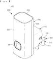
- FIG. 1 is a perspective diagram illustrating a front side of a water discharge device according to an example embodiment.
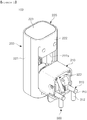
- FIG. 2 is a perspective diagram illustrating a rear side of a water discharge device according to an example embodiment.
- FIG. 3 is a perspective diagram illustrating a water discharge device in a state in which a body unit of the water discharge device is dissembled according to an example embodiment.
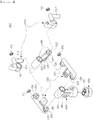
- FIG. 4 is an exploded perspective diagram illustrating a discharge unit of a water discharge device according to an example embodiment.
- FIG. 5 is a cross-sectional diagram illustrating a flow channel and a discharge channel of a discharge unit of a water discharge device according to an example embodiment.
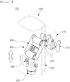
- FIGS. 6 to 8 are diagrams illustrating an operation of a water discharge device according to an example embodiment.
- An example embodiment of a water discharge device 100 may include a body unit 200 and a discharge unit 300.
- the body unit 200 may include a first body 210 and a second body 220.
- the first body 210 may be connected to a device body (not illustrated) of a water supply source (not illustrated) .
- the water supply source may be implemented as a water treatment device (not illustrated), such as a water purifier, or the like, for example.
- the first body 210 may be connected to the device body included in the water treatment device using a bolt, or the like. Accordingly, the first body 210 may be fixed to the device body of the water treatment device.
- the water supply source is not limited to any particular example, and may be implemented by any device which may supply water.
- the configuration in which the first body 210 is connected the device body of the water supply source, a device body of a water treatment device, for example, is not limited to any particular example, and any configuration in which the first body 210 may be connected to the device body may be used.
- a member through hole 211a may be formed in the first body 210 as illustrated in FIG. 3 .
- a plurality of hole forming portions 211 configured to extend from the first body 210 by a certain length may be formed in the first body 210, and the member through hole 211a may be formed in each of the plurality of hole forming portions 211.
- the configuration in which the member through hole 211a is formed in the first body 210 is not limited to any particular example, and may be implemented by any well-known configuration.
- a moving guide member 224 provided in the second body 220 may penetrate through the member through hole 211a. To this end, a portion of a side of the member through hole 211a of the first body 210, the hole forming portion 211 of the first body 210, for example, may pass through a moving guide hole 222a formed in the second body 220 and may be disposed in the second body 220.
- the second body 220 may be moveably connected to the first body 210.
- the configuration in which the second body 220 may be movably connected to the first body 210 is not limited to any particular example, and any configuration in which the second body 220 may be movably connected to the first body 210 may be used.
- a body through hole 212 may be formed in the first body 210.
- the discharge unit 300 connected to the second body 220 may penetrate through the body through hole 212 and may be connected to the water supply source. Accordingly, even when the second body 220 moves as illustrated in FIGS. 6 and 8 , moving up and down, for example, the discharge unit 300 may be continuously connected to the water supply source. Also, water from the water supply source may be externally discharged through the discharge unit 300 regardless of a moving position of the second body 220.
- the second body 220 may be movably connected to the first body 210.
- the moving guide member 224 may be provided in the second body 220.
- member connecting holes 222c and 223a may be formed in the second body 220, and one side and the other side of the moving guide member 224 may be inserted and connected to the member connecting holes 222c and 223a, respectively, thereby providing the moving guide member 224 in the second body 220.
- the moving guide hole 222a may be formed in the second body 220. A portion of a side of the member through hole 211a of the first body 210, the hole forming portion 211, for example, may pass through the moving guide hole 222a and may be disposed in the second body 220. In this state, the moving guide member 224 may penetrate through the member through hole 211a of the first body 210. Accordingly, the second body 220 may be movably connected to the first body 210.
- movement of the second body 220 may be guided by the moving guide member 224 and the moving guide hole 222a. Also, a moving distance of the second body 220 may be varied in accordance with a length of the moving guide hole 222a.
- the configuration in which the second body 220 may be movably connected to the first body 210 is not limited to any particular example, and any well-known configuration in which the second body 220 may be movably connected to the first body 210 may be used.
- An insertion connection hole 222b may be formed in the second body 220.
- a portion of a discharge member 350 included in the discharge unit 300 may be inserted and connected to the insertion connection hole 222b such that the portion of the discharge member 350 may be externally exposed. Accordingly, the discharge unit 300 may be connected to the second body 220 and may move along with the second body 220 when the second body 220 moves.
- the second body 220 may include a front side forming member 221, a rear side lower side forming member 222, and an upper side forming member 223.
- the front side forming member 221 may form a front side of the second body 220.
- the rear side lower side forming member 222 may form a rear side and a lower side of the second body 220.
- a lateral side of the second body 220 may be formed.
- an upper side of the second body 220 may be formed.
- a button BT for discharging water supplied from the water supply source from the discharge unit 300 externally may be provided in the front side forming member 221.
- the moving guide hole 222a, the insertion connection hole 222b, and the member connection hole 222c may be formed in the rear side lower side forming member 222.
- the member connecting hole 223a may be formed in the upper side forming member 223.
- the configuration of the second body 220 is not limited to any particular example, and any configuration in which the second body 220 may be movably connected to the first body 210 and may be connected to the discharge unit 300 may be used.
- a discharge guide member 225 may be provided in the second body 220. Water externally discharged from the discharge unit 300 may be guided by the discharge guide member 225.
- the discharge guide member 225 may be provided in a portion of the rear side lower side forming member 222 disposed around the insertion connection hole 222b, for example.
- a dispositional position of the discharge guide member 225 is not limited to any particular position, and the discharge guide member 225 may be provided at any position of the second body 220 at which the discharge guide member 225 may guide water externally discharged from the discharge unit 300.
- the discharge unit 300 may be connected to the second body 220 of the body unit 200. Accordingly, the discharge unit 300 may move along with the second body 220 when the second body 220 of the body unit 200 moves as illustrated in FIGS. 6 and 8 .
- the discharge unit 300 may be connected to the water supply source to discharge water from the water supply source externally.
- the discharge unit 300 may penetrate through the moving guide hole 222a of the second body 220 of the body unit 200 and through the body through hole 212 of the first body 210 and may be connected to the water supply source.
- the discharge unit 300 may be continuously connected to the water supply source. Also, water from the water supply source may be externally discharged through the discharge unit 300 regardless of a moving position of the discharge unit 300 that moves along with the second body 220.
- the discharge unit 300 may include a plurality of link members 320, 330, and 340.
- a flow channel RF in which water moves may be formed in each of the plurality of link members 320, 330, and 340 as illustrated in FIG. 5 .
- the plurality of link members 320, 330, and 340 may be rotatably connected to one another to connect the flow channels RF to one another in a sealed manner.
- the discharge unit 300 may move along with the second body 220, and water from the water supply source may flow in the flow channel RF of the discharge unit 300 and may be discharged externally regardless of a moving position of the discharge unit 300.
- the discharge unit 300 may move along with the second body 220 of the body unit 200, and water from the water supply source may be discharged externally through the discharge unit 300. Accordingly, the water discharge device 100 may be able to move in a relatively small space.
- each of the plurality of link members 320, 330, and 340 does not have a curved portion, such as a curved portion of a flexible tube, foreign objects may not remain in the link members. Accordingly, hygiene of the water discharge device 100 may improve such that water may be supplied to a user without foreign objects.
- the plurality of link members 320, 330, and 340 may not be deformed or broken. Accordingly, water from the water supply source may be smoothly discharged externally through the water discharge device 100.
- the plurality of link members 320, 330, and 340 may include the first link member 320, the second link member 330, and the third link member 340.
- the number of the plurality of link members 320, 330, and 340 is not limited to any particular number.
- the number of the plurality of link members 320, 330, and 340 may be two or more.
- the first link member 320 may be rotatably connected to a supply source connection member 310 included in the discharge unit 300.
- the second link member 330 may be rotatably connected to the first link member 320.
- the third link member 340 may be rotatably connected to the second link member 330.
- the discharge unit 300 may further include the supply source connection member 310.
- the flow channel RF may also be formed in the supply source connection member 310.
- the supply source connection member 310 may be connected to the water supply source.
- the flow channel RF may be configured to extend in the supply source connection member 310 and a connection port 312 connected to a connection pipe (not illustrated) or directly connected to the water supply source may be formed in the supply source connection member 310. Accordingly, water from the water supply source may flow into the flow channel RF of the supply source connection member 310 through the connection port 312 and may flow in the flow channel RF of the supply source connection member 310.
- the link member 320 of the plurality of link members 320, 330, and 340 disposed on one side, the first link member 320, for example, may be rotatably connected to the supply source connection member 310.
- First rotary connection portions 311, 321, and 341 may be disposed in the supply source connection member 310 and the partial link members 320 and 340 of the plurality of link members 320, 330, and 340, respectively.
- the first rotary connection portions 311, 321, and 341 may be disposed in the supply source connection member 310, the first link member 320, and the third link member 340, respectively.
- Second rotary connection portions 322 and 331 rotatably connected to the first rotary connection portions 311, 321, and 341 may be disposed in the partial link members 320 and 330 of the plurality of link members 320, 330, and 340.
- the second rotary connection portions 322 and 331 may be disposed in the first link member 320 and the second link member 330, respectively.
- only the second rotary connection portion 331 may be disposed in the second link member 330.
- the flow channels RF of the supply source connection member 310 and the plurality of link members 320, 330, and 340 may be configured to extend to the first rotary connection portions 311, 321, and 341 and the second rotary connection portions 322 and 331 of the supply source connection member 310 and the plurality of link members 320, 330, and 340.
- a sealing member OR may be provided in each of the second rotary connection portions 322 and 331, and when the second rotary connection portions 322 and 331 are inserted into the first rotary connection portions 311, 321, and 341, a region between the second rotary connection portions 322 and 331 and the first rotary connection portions 311, 321, and 341 may be sealed by the sealing member OR.
- the supply source connection member 310 may be rotatably connected to the plurality of link members 320, 330, and 340, the first to third link members 320, 330, and 340, for example, to connect the flow channels RF to one another in a sealed manner.
- the configuration in which the supply source connection member 310 may be rotatably connected to the plurality of link members 320, 330, and 340 to connect the flow channels RF to one another in a sealed manner is not limited to any particular example, and any well-known configuration may be used.
- the discharge unit 300 may further include the discharge member 350.
- the discharge member 350 may be connected to the link member 340 of the plurality of link members 320, 330, and 340 disposed on the other side, and to the second body 220 of the body unit 200.
- the discharge member 350 may be inserted and connected to the third link member 340.
- the discharge member 350 may be inserted and connected to the insertion connection hole 222b of the second body 220 of the body unit 200 such that the discharge member 350 may be connected to the second body 220 of the body unit 200.
- the configuration in which the discharge member 350 may be connected to the third link member 340 of the plurality of link members 320, 330, and 340 disposed on the other side and the configuration in which the discharge member 350 may be connected to the second body 220 of the body unit 200 may not be limited to any particular examples, and any well-known configurations may be used.
- a discharge channel RD may be formed in the discharge member 350.
- the discharge channel RD may be connected to the flow channel RF of the link member 340 of the plurality of link members 320, 330, and 340 disposed on the other side, the third link member 340, for example, and to an external entity. Accordingly, water flowing into the flow channel RF of the supply source connection member 310 through the connection port 312 of the supply source connection member 310 from the water supply source may flow in the flow channels RF of the plurality of link members 320, 330, and 340 and may be externally discharged through the discharge channel RD of the discharge member 350.
- An open portion of the flow channel RF of each of the supply source connection member 310 and the plurality of link members 320, 330, and 340 may be blocked by a plug member PG.
- the water discharge device described in the aforementioned example embodiment when used, by using the plurality of link members, rather than using a flexible tube, the water discharge device may be able to move and may discharge water from the water supply source externally, the water discharge device may be able to move in a relatively small space, hygiene of the water discharge device may improve such that water may be supplied to a user without foreign objects, and water from the water supply source may be smoothly discharged through the water discharge device.
- the water discharge device described above is not limited to the features described in the example embodiments set forth herein, but overall or some of the example embodiments may be selectively combined and configured to implement a variety of modifications.
Landscapes
- Engineering & Computer Science (AREA)
- Water Supply & Treatment (AREA)
- Chemical & Material Sciences (AREA)
- Chemical Kinetics & Catalysis (AREA)
- Devices For Dispensing Beverages (AREA)
- Nozzles (AREA)
- Domestic Plumbing Installations (AREA)
Abstract
Description
- The present disclosure relates to a water discharge device discharging water from a water supply source externally.
- A water discharge device is connected to a water supply source, and discharges water from the water supply source externally to supply water to a user. A water discharge device may be connected to a water treatment device such as a water purifier, or the like, and may discharge filtered water, such as water filtered in a water treatment device, externally, and may supply the water to a user.
- A water discharge device may be moveably provided in a water supply source such as a water treatment device. Accordingly, a user may be supplied with water from a water supply source through a water discharge device while appropriately adjusting a height of the water discharge device to a height desired by the user or in accordance with an intended purpose.
- Generally, when a water discharge device is movably provided in a water supply source such as a water treatment device, or the like, the water discharge device may be connected to the water supply source such as a water treatment device, or the like, through a flexible tube to allow the water discharge device to move smoothly.
- The above-described configuration, however, may occupy a relatively large space as a space in which the flexible tube is disposed may be required. Also, as a flexible tube is curved, foreign objects may remain in a curved portion of the flexible tube such that a user may be supplied with water including foreign objects. Further, when a flexible tube is used for a long time, the flexible tube may be deformed or broken such that water from a water supply source may not be smoothly discharged through a water discharge device.
- An aspect of the present disclosure is to address at least one of the above demands or issues occurring in the related art.
- An aspect of the present disclosure is to provide a water discharge device which may move and may discharge water from a water supply source externally without using a flexible tube.
- Another aspect of the present disclosure is to provide a water discharge device which may move in a relatively small space.
- Another aspect of the present disclosure is to provide a water discharge device which may have improved sanitation to supply water without foreign objects to a user.
- Another aspect of the present disclosure is to provide a water discharge device which may smoothly discharge water from a water supply source.
- According to an aspect of the present disclosure, a water discharge device according to an example embodiment includes features as outlined below.
- According to an aspect of the present disclosure, a water discharge device includes a body unit including a first body and a second body moveably connected to the first body; and a discharge unit connected to the second body, moving along with the second body, and connected to a water supply source to discharge water from the water supply source externally, and the discharge unit includes a plurality of link members having flow channels through which water flows, respectively, and rotatably connected to one another to connect the flow channels to one another in a sealed manner.
- In this case, the discharge unit may further include a supply source connection member having the flow channel and connected to the water supply source, and a link member of the plurality of link members disposed on one side is rotatably connected to the supply source connection member.
- Also, each of the supply source connection member and partial link members of the plurality of link members may include a first rotary connection portion, each of partial link members of the plurality of link members may include a second rotary connection portion rotatably connected to the first rotary connection portion, and the flow channel may be configured to extend to the first rotary connection portion and the second rotary connection portion.
- The second rotary connection portion may be inserted into and rotatably connected to the first rotary connection portion.
- The second rotary connection portion may include a sealing member for sealing a region between the first rotary connection portion and the second rotary connection portion.
- The plurality of link members may include a first link member rotatably connected to the supply source connection member, a second link member rotatably connected to the first link member, and a third link member rotatably connected to the second link member.
- Each of the supply source connection member, the first link member, and the third link member may include the first rotary connection portion, and each of the first link member and the second link member may include the second rotary connection portion.
- The water discharge device may further include a discharge member connected to a link member of the plurality of link members disposed on the other side and to the second body, and including a discharge channel connected to the flow channel of the link member disposed on the other side and to an external entity.
- The first body may include a member through hole, and the second body may include a moving guide member configured to penetrate the member through hole.
- The second body may include a moving guide hole, and a portion of the first body disposed on a side of the member through hole may pass through the moving guide hole and may be disposed in the second body.
- The discharge unit may penetrate through the moving guide hole and a body through hole formed in the first body, and may be connected to the water supply source.
- The second body may include an insertion connection hole to which a portion of the discharge member is inserted and connected such that the portion of the discharge member may be externally exposed.
- As set forth above, according to an example embodiment in the present disclosure, a water discharge device may be able to move and may discharge water from a water supply source externally using a plurality of link members, rather than using a flexible tube.
- Also, according to an example embodiment in the present disclosure, the water discharge device may be able to move in a relatively small space.
- Further, according to an example embodiment in the present disclosure, hygiene of the water discharge device may improve such that water may be supplied to a user without foreign objects.
- Also, according to an example embodiment in the present disclosure, water from a water supply source may be smoothly discharged through the water discharge device.
-
-
FIG. 1 is a perspective diagram illustrating a front side of a water discharge device according to an example embodiment in the present disclosure; -
FIG. 2 is a perspective diagram illustrating a rear side of a water discharge device according to an example embodiment in the present disclosure; -
FIG. 3 is a perspective diagram illustrating a water discharge device in a state in which a body unit of the water discharge device is dissembled according to an example embodiment in the present disclosure; -
FIG. 4 is an exploded perspective diagram illustrating a discharge unit of a water discharge device according to an example embodiment in the present disclosure; -
FIG. 5 is a cross-sectional diagram illustrating a flow channel and a discharge channel of a discharge unit of a water discharge device according to an example embodiment in the present disclosure; -
FIGS. 6 to 8 are diagrams illustrating an operation of a water discharge device according to an example embodiment in the present disclosure. - To help understanding of features of the present invention as above, example embodiments of a water discharge device will be described in greater detail.
- In the descriptions below, the present disclosure will be described based on the most appropriate example embodiments for an understanding of technical features in the present disclosure. It is to be understood that the technical features of the present invention are not limited to the example embodiments, and the present invention may be implemented as in the example embodiments described herein. Thus, the present invention may be modified in various manners through the example embodiments described herein within the technical scope of the present invention, and the modified example embodiments are to be included in the technical scope of the present invention. Also, to help in an understanding of the example embodiments, as for reference numerals in the attached drawings, relevant elements among elements having the same function in the example embodiments are indicated by the same or similar forms of reference numeral.
- In the descriptions below, an example embodiment of a water discharge device according to the present disclosure will be described with reference to
FIGS. 1 to 8 . -
FIG. 1 is a perspective diagram illustrating a front side of a water discharge device according to an example embodiment.FIG. 2 is a perspective diagram illustrating a rear side of a water discharge device according to an example embodiment. -
FIG. 3 is a perspective diagram illustrating a water discharge device in a state in which a body unit of the water discharge device is dissembled according to an example embodiment.FIG. 4 is an exploded perspective diagram illustrating a discharge unit of a water discharge device according to an example embodiment.FIG. 5 is a cross-sectional diagram illustrating a flow channel and a discharge channel of a discharge unit of a water discharge device according to an example embodiment. -
FIGS. 6 to 8 are diagrams illustrating an operation of a water discharge device according to an example embodiment. - An example embodiment of a
water discharge device 100 may include abody unit 200 and adischarge unit 300. - The
body unit 200 may include afirst body 210 and asecond body 220. - The
first body 210 may be connected to a device body (not illustrated) of a water supply source (not illustrated) . The water supply source may be implemented as a water treatment device (not illustrated), such as a water purifier, or the like, for example. Thefirst body 210 may be connected to the device body included in the water treatment device using a bolt, or the like. Accordingly, thefirst body 210 may be fixed to the device body of the water treatment device. - The water supply source is not limited to any particular example, and may be implemented by any device which may supply water. The configuration in which the
first body 210 is connected the device body of the water supply source, a device body of a water treatment device, for example, is not limited to any particular example, and any configuration in which thefirst body 210 may be connected to the device body may be used. - A member through
hole 211a may be formed in thefirst body 210 as illustrated inFIG. 3 . For example, a plurality ofhole forming portions 211 configured to extend from thefirst body 210 by a certain length may be formed in thefirst body 210, and the member throughhole 211a may be formed in each of the plurality ofhole forming portions 211. The configuration in which the member throughhole 211a is formed in thefirst body 210, however, is not limited to any particular example, and may be implemented by any well-known configuration. - A moving
guide member 224 provided in thesecond body 220 may penetrate through the member throughhole 211a. To this end, a portion of a side of the member throughhole 211a of thefirst body 210, thehole forming portion 211 of thefirst body 210, for example, may pass through a movingguide hole 222a formed in thesecond body 220 and may be disposed in thesecond body 220. - Accordingly, the
second body 220 may be moveably connected to thefirst body 210. However, the configuration in which thesecond body 220 may be movably connected to thefirst body 210 is not limited to any particular example, and any configuration in which thesecond body 220 may be movably connected to thefirst body 210 may be used. - A body through hole 212 may be formed in the
first body 210. Thedischarge unit 300 connected to thesecond body 220 may penetrate through the body through hole 212 and may be connected to the water supply source. Accordingly, even when thesecond body 220 moves as illustrated inFIGS. 6 and8 , moving up and down, for example, thedischarge unit 300 may be continuously connected to the water supply source. Also, water from the water supply source may be externally discharged through thedischarge unit 300 regardless of a moving position of thesecond body 220. - The
second body 220 may be movably connected to thefirst body 210. - As illustrated in
FIG. 3 , the movingguide member 224 may be provided in thesecond body 220. For example,member connecting holes second body 220, and one side and the other side of the movingguide member 224 may be inserted and connected to themember connecting holes guide member 224 in thesecond body 220. Also, the movingguide hole 222a may be formed in thesecond body 220. A portion of a side of the member throughhole 211a of thefirst body 210, thehole forming portion 211, for example, may pass through the movingguide hole 222a and may be disposed in thesecond body 220. In this state, the movingguide member 224 may penetrate through the member throughhole 211a of thefirst body 210. Accordingly, thesecond body 220 may be movably connected to thefirst body 210. - In the configuration described above, movement of the
second body 220 may be guided by the movingguide member 224 and the movingguide hole 222a. Also, a moving distance of thesecond body 220 may be varied in accordance with a length of the movingguide hole 222a. - The configuration in which the
second body 220 may be movably connected to thefirst body 210, however, is not limited to any particular example, and any well-known configuration in which thesecond body 220 may be movably connected to thefirst body 210 may be used. - An
insertion connection hole 222b may be formed in thesecond body 220. A portion of adischarge member 350 included in thedischarge unit 300 may be inserted and connected to theinsertion connection hole 222b such that the portion of thedischarge member 350 may be externally exposed. Accordingly, thedischarge unit 300 may be connected to thesecond body 220 and may move along with thesecond body 220 when thesecond body 220 moves. - The
second body 220 may include a frontside forming member 221, a rear side lowerside forming member 222, and an upperside forming member 223. The frontside forming member 221 may form a front side of thesecond body 220. The rear side lowerside forming member 222 may form a rear side and a lower side of thesecond body 220. By connecting the frontside forming member 221 to the rear side lowerside forming member 222, a lateral side of thesecond body 220 may be formed. Also, by connecting the upperside forming member 223 to the frontside forming member 221 and the rear side lowerside forming member 222, an upper side of thesecond body 220 may be formed. - A button BT for discharging water supplied from the water supply source from the
discharge unit 300 externally may be provided in the frontside forming member 221. The movingguide hole 222a, theinsertion connection hole 222b, and themember connection hole 222c may be formed in the rear side lowerside forming member 222. Themember connecting hole 223a may be formed in the upperside forming member 223. - The configuration of the
second body 220, however, is not limited to any particular example, and any configuration in which thesecond body 220 may be movably connected to thefirst body 210 and may be connected to thedischarge unit 300 may be used. - A
discharge guide member 225 may be provided in thesecond body 220. Water externally discharged from thedischarge unit 300 may be guided by thedischarge guide member 225. Thedischarge guide member 225 may be provided in a portion of the rear side lowerside forming member 222 disposed around theinsertion connection hole 222b, for example. However, a dispositional position of thedischarge guide member 225 is not limited to any particular position, and thedischarge guide member 225 may be provided at any position of thesecond body 220 at which thedischarge guide member 225 may guide water externally discharged from thedischarge unit 300. - The
discharge unit 300 may be connected to thesecond body 220 of thebody unit 200. Accordingly, thedischarge unit 300 may move along with thesecond body 220 when thesecond body 220 of thebody unit 200 moves as illustrated inFIGS. 6 and8 . - The
discharge unit 300 may be connected to the water supply source to discharge water from the water supply source externally. For example, thedischarge unit 300 may penetrate through the movingguide hole 222a of thesecond body 220 of thebody unit 200 and through the body through hole 212 of thefirst body 210 and may be connected to the water supply source. - Accordingly, even when the
second body 220 of thebody unit 200 moves, thedischarge unit 300 may be continuously connected to the water supply source. Also, water from the water supply source may be externally discharged through thedischarge unit 300 regardless of a moving position of thedischarge unit 300 that moves along with thesecond body 220. - The
discharge unit 300 may include a plurality oflink members link members FIG. 5 . The plurality oflink members - Accordingly, when the
second body 220 of thebody unit 200 moves, thedischarge unit 300 may move along with thesecond body 220, and water from the water supply source may flow in the flow channel RF of thedischarge unit 300 and may be discharged externally regardless of a moving position of thedischarge unit 300. - As described above, by using the plurality of
link members discharge unit 300 may move along with thesecond body 220 of thebody unit 200, and water from the water supply source may be discharged externally through thedischarge unit 300. Accordingly, thewater discharge device 100 may be able to move in a relatively small space. - Also, as each of the plurality of
link members water discharge device 100 may improve such that water may be supplied to a user without foreign objects. - Also, even when the plurality of
link members link members water discharge device 100. - As illustrated in
FIGS. 3 and4 , the plurality oflink members first link member 320, thesecond link member 330, and thethird link member 340. The number of the plurality oflink members link members - The
first link member 320 may be rotatably connected to a supplysource connection member 310 included in thedischarge unit 300. Thesecond link member 330 may be rotatably connected to thefirst link member 320. Thethird link member 340 may be rotatably connected to thesecond link member 330. - The
discharge unit 300 may further include the supplysource connection member 310. The flow channel RF may also be formed in the supplysource connection member 310. The supplysource connection member 310 may be connected to the water supply source. For example, the flow channel RF may be configured to extend in the supplysource connection member 310 and aconnection port 312 connected to a connection pipe (not illustrated) or directly connected to the water supply source may be formed in the supplysource connection member 310. Accordingly, water from the water supply source may flow into the flow channel RF of the supplysource connection member 310 through theconnection port 312 and may flow in the flow channel RF of the supplysource connection member 310. - The
link member 320 of the plurality oflink members first link member 320, for example, may be rotatably connected to the supplysource connection member 310. - First
rotary connection portions source connection member 310 and thepartial link members link members FIG. 3 , the firstrotary connection portions source connection member 310, thefirst link member 320, and thethird link member 340, respectively. - Second
rotary connection portions rotary connection portions partial link members link members FIG. 3 , the secondrotary connection portions first link member 320 and thesecond link member 330, respectively. In this case, only the secondrotary connection portion 331 may be disposed in thesecond link member 330. - The flow channels RF of the supply
source connection member 310 and the plurality oflink members rotary connection portions rotary connection portions source connection member 310 and the plurality oflink members - Also, a sealing member OR may be provided in each of the second
rotary connection portions rotary connection portions rotary connection portions rotary connection portions rotary connection portions - By the configuration described above, the supply
source connection member 310 may be rotatably connected to the plurality oflink members third link members source connection member 310 may be rotatably connected to the plurality oflink members - The
discharge unit 300 may further include thedischarge member 350. Thedischarge member 350 may be connected to thelink member 340 of the plurality oflink members second body 220 of thebody unit 200. - For example, the
discharge member 350 may be inserted and connected to thethird link member 340. Also, thedischarge member 350 may be inserted and connected to theinsertion connection hole 222b of thesecond body 220 of thebody unit 200 such that thedischarge member 350 may be connected to thesecond body 220 of thebody unit 200. The configuration in which thedischarge member 350 may be connected to thethird link member 340 of the plurality oflink members discharge member 350 may be connected to thesecond body 220 of thebody unit 200, however, may not be limited to any particular examples, and any well-known configurations may be used. - A discharge channel RD may be formed in the
discharge member 350. The discharge channel RD may be connected to the flow channel RF of thelink member 340 of the plurality oflink members third link member 340, for example, and to an external entity. Accordingly, water flowing into the flow channel RF of the supplysource connection member 310 through theconnection port 312 of the supplysource connection member 310 from the water supply source may flow in the flow channels RF of the plurality oflink members discharge member 350. - An open portion of the flow channel RF of each of the supply
source connection member 310 and the plurality oflink members - When the water discharge device described in the aforementioned example embodiment is used, by using the plurality of link members, rather than using a flexible tube, the water discharge device may be able to move and may discharge water from the water supply source externally, the water discharge device may be able to move in a relatively small space, hygiene of the water discharge device may improve such that water may be supplied to a user without foreign objects, and water from the water supply source may be smoothly discharged through the water discharge device.
- The water discharge device described above is not limited to the features described in the example embodiments set forth herein, but overall or some of the example embodiments may be selectively combined and configured to implement a variety of modifications.
Claims (12)
- A water discharge device, comprising:a body unit including a first body and a second body moveably connected to the first body; anda discharge unit connected to the second body, moving along with the second body, and connected to a water supply source to discharge water from the water supply source externally,wherein the discharge unit includes a plurality of link members having flow channels through which water flows, respectively, and rotatably connected to one another to connect the flow channels to one another in a sealed manner.
- The water discharge device of claim 1, wherein the discharge unit further includes a supply source connection member having the flow channel and connected to the water supply source, and a link member of the plurality of link members disposed on one side is rotatably connected to the supply source connection member.
- The water discharge device of claim 2,
wherein each of the supply source connection member and partial link members of the plurality of link members includes a first rotary connection portion,
wherein each of partial link members of the plurality of link members includes a second rotary connection portion rotatably connected to the first rotary connection portion, and
wherein the flow channel is configured to extend to the first rotary connection portion and the second rotary connection portion. - The water discharge device of claim 3, wherein the second rotary connection portion is inserted into and rotatably connected to the first rotary connection portion.
- The water discharge device of claim 4, wherein the second rotary connection portion includes a sealing member for sealing a region between the first rotary connection portion and the second rotary connection portion.
- The water discharge device of claim 3, wherein the plurality of link members includes a first link member rotatably connected to the supply source connection member, a second link member rotatably connected to the first link member, and a third link member rotatably connected to the second link member.
- The water discharge device of claim 6,
wherein each of the supply source connection member, the first link member, and the third link member includes the first rotary connection portion, and
wherein each of the first link member and the second link member includes the second rotary connection portion. - The water discharge device of claim 2, further comprising:
a discharge member connected to a link member of the plurality of link members disposed on the other side and to the second body, and including a discharge channel connected to the flow channel of the link member disposed on the other side and to an external entity. - The water discharge device of claim 1,
wherein the first body includes a member through hole, and
wherein the second body includes a moving guide member configured to penetrate the member through hole. - The water discharge device of claim 9,
wherein the second body includes a moving guide hole, and
wherein a portion of the first body disposed on a side of the member through hole passes through the moving guide hole and is disposed in the second body. - The water discharge device of claim 10, wherein the discharge unit penetrates through the moving guide hole and a body through hole formed in the first body, and is connected to the water supply source.
- The water discharge device of claim 8, wherein the second body includes an insertion connection hole to which a portion of the discharge member is inserted and connected such that the portion of the discharge member is externally exposed.
Applications Claiming Priority (2)
| Application Number | Priority Date | Filing Date | Title |
|---|---|---|---|
| KR1020170052238A KR102064180B1 (en) | 2017-04-24 | 2017-04-24 | Water discharging apparatus |
| PCT/KR2018/004437 WO2018199533A1 (en) | 2017-04-24 | 2018-04-17 | Water discharge device |
Publications (3)
| Publication Number | Publication Date |
|---|---|
| EP3613701A1 true EP3613701A1 (en) | 2020-02-26 |
| EP3613701A4 EP3613701A4 (en) | 2020-04-15 |
| EP3613701B1 EP3613701B1 (en) | 2021-06-02 |
Family
ID=63920316
Family Applications (1)
| Application Number | Title | Priority Date | Filing Date |
|---|---|---|---|
| EP18791239.9A Active EP3613701B1 (en) | 2017-04-24 | 2018-04-17 | Water discharge device |
Country Status (6)
| Country | Link |
|---|---|
| US (1) | US11370647B2 (en) |
| EP (1) | EP3613701B1 (en) |
| JP (1) | JP6929965B2 (en) |
| KR (1) | KR102064180B1 (en) |
| CN (1) | CN110536859B (en) |
| WO (1) | WO2018199533A1 (en) |
Families Citing this family (2)
| Publication number | Priority date | Publication date | Assignee | Title |
|---|---|---|---|---|
| KR102223509B1 (en) * | 2019-05-10 | 2021-03-05 | 주식회사 바디프랜드 | Water treatment apparatus in which the flow path is maintained when the water outlet module is moved |
| KR20230130956A (en) | 2022-03-04 | 2023-09-12 | 코웨이 주식회사 | Water purifier |
Family Cites Families (18)
| Publication number | Priority date | Publication date | Assignee | Title |
|---|---|---|---|---|
| GB438817A (en) * | 1934-08-15 | 1935-11-25 | Thomas Hall | Improvements in cellar equipments for drawing beer |
| US2240392A (en) * | 1938-12-23 | 1941-04-29 | B S Allen | Nozzle |
| US3666179A (en) * | 1970-09-28 | 1972-05-30 | Peschcke Andreas P | Adjustable shower apparatus |
| US3726318A (en) * | 1971-10-28 | 1973-04-10 | Pryde Inc | Faucet |
| US4437497A (en) * | 1981-09-23 | 1984-03-20 | Enander Frederick A | Ultrasonic control of filling a container |
| JP3441669B2 (en) | 1999-03-12 | 2003-09-02 | 株式会社三栄水栓製作所 | Switching cock |
| DE10239595B4 (en) * | 2002-08-28 | 2006-02-09 | Niro-Plan Ag | Dispenser for drinks |
| DK1472963T3 (en) * | 2003-05-02 | 2009-03-30 | Schaerer Ag M | Device for delivering milk and / or milk foam |
| FR2879426B1 (en) | 2004-12-21 | 2007-02-23 | Seb Sa | COFFEE MACHINE HAVING A STEAM NOZZLE |
| DE202005011476U1 (en) * | 2005-07-21 | 2005-10-27 | Eugster/Frismag Ag | Coffee machine, has height adjustable and lockable discharging unit supported at housing by longitudinal ball bearing used as clamping unit, where bearing encompasses longitudinal ball bearing axle which is used as another clamping unit |
| KR101051775B1 (en) * | 2009-08-11 | 2011-07-26 | 손종채 | Rotary Fountain Drive |
| KR101106580B1 (en) | 2009-09-21 | 2012-01-19 | 임동원 | Euro Adapter |
| KR20120070286A (en) * | 2010-12-21 | 2012-06-29 | 웅진코웨이주식회사 | Cock assembly and water treatment apparatus having the same |
| EP2599412A1 (en) * | 2011-12-01 | 2013-06-05 | Nestec S.A. | A beverage preparation machine |
| US9568132B2 (en) * | 2012-07-13 | 2017-02-14 | Kohler Co. | Clutched joint for articulating faucet |
| KR101988946B1 (en) * | 2012-09-06 | 2019-06-12 | 웅진코웨이 주식회사 | Moving structure of water dicharging unit |
| EP2965671B1 (en) * | 2014-07-07 | 2018-02-28 | De'Longhi Appliances S.r.l. | Milk container that can be associated with a coffee machine and coffee machine having such a milk container |
| KR102307150B1 (en) * | 2014-09-12 | 2021-10-05 | 코웨이 주식회사 | Beverage discharging apparatus |
-
2017
- 2017-04-24 KR KR1020170052238A patent/KR102064180B1/en active Active
-
2018
- 2018-04-17 CN CN201880025319.6A patent/CN110536859B/en active Active
- 2018-04-17 EP EP18791239.9A patent/EP3613701B1/en active Active
- 2018-04-17 JP JP2019557803A patent/JP6929965B2/en active Active
- 2018-04-17 WO PCT/KR2018/004437 patent/WO2018199533A1/en not_active Ceased
- 2018-04-17 US US16/607,288 patent/US11370647B2/en active Active
Also Published As
| Publication number | Publication date |
|---|---|
| EP3613701B1 (en) | 2021-06-02 |
| KR102064180B1 (en) | 2020-01-09 |
| US20200384390A1 (en) | 2020-12-10 |
| US11370647B2 (en) | 2022-06-28 |
| JP6929965B2 (en) | 2021-09-01 |
| CN110536859B (en) | 2021-06-25 |
| WO2018199533A1 (en) | 2018-11-01 |
| EP3613701A4 (en) | 2020-04-15 |
| JP2020517540A (en) | 2020-06-18 |
| KR20180118931A (en) | 2018-11-01 |
| CN110536859A (en) | 2019-12-03 |
Similar Documents
| Publication | Publication Date | Title |
|---|---|---|
| ES2964059T3 (en) | Health insertion unit | |
| USD886369S1 (en) | Face mask | |
| US20160339457A1 (en) | Water outlet valve core of a wall mounted shower head and water output device using the same | |
| US11370647B2 (en) | Water discharge device | |
| ES2630192T3 (en) | Low noise toilet | |
| NZ773197A (en) | Blood control septum and related systems | |
| ES2633193T3 (en) | Toilet purge apparatus | |
| BR112017018705B1 (en) | JET REGULATOR WITH A JET REGULATOR HOUSING | |
| WO2017011838A8 (en) | Catheter | |
| ES2169621B1 (en) | WINDOW TYPE AIR CONDITIONER. | |
| US2092400A (en) | Valve means | |
| EP2599557A1 (en) | Portable shower head with air inlet cover | |
| US11553998B2 (en) | Water toothpick | |
| US3348537A (en) | Combination breathing valve and speaking diaphragm unit | |
| Hujdurović et al. | Graphs vertex-partitionable into strong cliques | |
| EP3632293A3 (en) | Multi lumen access device | |
| US20160319526A1 (en) | Faucet water filtering device | |
| ES2818616T3 (en) | Feeding device for a discharge tank | |
| CN202223737U (en) | Abdominal cavity drainage tube | |
| US9630190B2 (en) | Multi-function water output device | |
| CN211325228U (en) | Multi-channel working sleeve | |
| CN203677598U (en) | Decompression collection device | |
| CN206044586U (en) | A kind of hysteroscope water-tight device | |
| EP3067119A1 (en) | Long-distance fluid ejection apparatus | |
| CN208308477U (en) | A kind of waste water proportioner |
Legal Events
| Date | Code | Title | Description |
|---|---|---|---|
| STAA | Information on the status of an ep patent application or granted ep patent |
Free format text: STATUS: THE INTERNATIONAL PUBLICATION HAS BEEN MADE |
|
| PUAI | Public reference made under article 153(3) epc to a published international application that has entered the european phase |
Free format text: ORIGINAL CODE: 0009012 |
|
| STAA | Information on the status of an ep patent application or granted ep patent |
Free format text: STATUS: REQUEST FOR EXAMINATION WAS MADE |
|
| 17P | Request for examination filed |
Effective date: 20191119 |
|
| AK | Designated contracting states |
Kind code of ref document: A1 Designated state(s): AL AT BE BG CH CY CZ DE DK EE ES FI FR GB GR HR HU IE IS IT LI LT LU LV MC MK MT NL NO PL PT RO RS SE SI SK SM TR |
|
| AX | Request for extension of the european patent |
Extension state: BA ME |
|
| A4 | Supplementary search report drawn up and despatched |
Effective date: 20200317 |
|
| RIC1 | Information provided on ipc code assigned before grant |
Ipc: B67D 1/12 20060101AFI20200311BHEP Ipc: B67D 1/00 20060101ALI20200311BHEP Ipc: B01D 35/04 20060101ALI20200311BHEP |
|
| DAV | Request for validation of the european patent (deleted) | ||
| DAX | Request for extension of the european patent (deleted) | ||
| GRAP | Despatch of communication of intention to grant a patent |
Free format text: ORIGINAL CODE: EPIDOSNIGR1 |
|
| STAA | Information on the status of an ep patent application or granted ep patent |
Free format text: STATUS: GRANT OF PATENT IS INTENDED |
|
| INTG | Intention to grant announced |
Effective date: 20201109 |
|
| GRAS | Grant fee paid |
Free format text: ORIGINAL CODE: EPIDOSNIGR3 |
|
| GRAA | (expected) grant |
Free format text: ORIGINAL CODE: 0009210 |
|
| STAA | Information on the status of an ep patent application or granted ep patent |
Free format text: STATUS: THE PATENT HAS BEEN GRANTED |
|
| REG | Reference to a national code |
Ref country code: CH Ref legal event code: EP |
|
| AK | Designated contracting states |
Kind code of ref document: B1 Designated state(s): AL AT BE BG CH CY CZ DE DK EE ES FI FR GB GR HR HU IE IS IT LI LT LU LV MC MK MT NL NO PL PT RO RS SE SI SK SM TR |
|
| REG | Reference to a national code |
Ref country code: GB Ref legal event code: FG4D |
|
| REG | Reference to a national code |
Ref country code: AT Ref legal event code: REF Ref document number: 1398291 Country of ref document: AT Kind code of ref document: T Effective date: 20210615 |
|
| REG | Reference to a national code |
Ref country code: IE Ref legal event code: FG4D |
|
| REG | Reference to a national code |
Ref country code: DE Ref legal event code: R096 Ref document number: 602018018165 Country of ref document: DE |
|
| REG | Reference to a national code |
Ref country code: LT Ref legal event code: MG9D |
|
| PG25 | Lapsed in a contracting state [announced via postgrant information from national office to epo] |
Ref country code: LT Free format text: LAPSE BECAUSE OF FAILURE TO SUBMIT A TRANSLATION OF THE DESCRIPTION OR TO PAY THE FEE WITHIN THE PRESCRIBED TIME-LIMIT Effective date: 20210602 Ref country code: HR Free format text: LAPSE BECAUSE OF FAILURE TO SUBMIT A TRANSLATION OF THE DESCRIPTION OR TO PAY THE FEE WITHIN THE PRESCRIBED TIME-LIMIT Effective date: 20210602 Ref country code: FI Free format text: LAPSE BECAUSE OF FAILURE TO SUBMIT A TRANSLATION OF THE DESCRIPTION OR TO PAY THE FEE WITHIN THE PRESCRIBED TIME-LIMIT Effective date: 20210602 Ref country code: BG Free format text: LAPSE BECAUSE OF FAILURE TO SUBMIT A TRANSLATION OF THE DESCRIPTION OR TO PAY THE FEE WITHIN THE PRESCRIBED TIME-LIMIT Effective date: 20210902 |
|
| REG | Reference to a national code |
Ref country code: NL Ref legal event code: MP Effective date: 20210602 |
|
| REG | Reference to a national code |
Ref country code: AT Ref legal event code: MK05 Ref document number: 1398291 Country of ref document: AT Kind code of ref document: T Effective date: 20210602 |
|
| PG25 | Lapsed in a contracting state [announced via postgrant information from national office to epo] |
Ref country code: NO Free format text: LAPSE BECAUSE OF FAILURE TO SUBMIT A TRANSLATION OF THE DESCRIPTION OR TO PAY THE FEE WITHIN THE PRESCRIBED TIME-LIMIT Effective date: 20210902 Ref country code: LV Free format text: LAPSE BECAUSE OF FAILURE TO SUBMIT A TRANSLATION OF THE DESCRIPTION OR TO PAY THE FEE WITHIN THE PRESCRIBED TIME-LIMIT Effective date: 20210602 Ref country code: PL Free format text: LAPSE BECAUSE OF FAILURE TO SUBMIT A TRANSLATION OF THE DESCRIPTION OR TO PAY THE FEE WITHIN THE PRESCRIBED TIME-LIMIT Effective date: 20210602 Ref country code: SE Free format text: LAPSE BECAUSE OF FAILURE TO SUBMIT A TRANSLATION OF THE DESCRIPTION OR TO PAY THE FEE WITHIN THE PRESCRIBED TIME-LIMIT Effective date: 20210602 Ref country code: RS Free format text: LAPSE BECAUSE OF FAILURE TO SUBMIT A TRANSLATION OF THE DESCRIPTION OR TO PAY THE FEE WITHIN THE PRESCRIBED TIME-LIMIT Effective date: 20210602 Ref country code: GR Free format text: LAPSE BECAUSE OF FAILURE TO SUBMIT A TRANSLATION OF THE DESCRIPTION OR TO PAY THE FEE WITHIN THE PRESCRIBED TIME-LIMIT Effective date: 20210903 |
|
| PG25 | Lapsed in a contracting state [announced via postgrant information from national office to epo] |
Ref country code: CZ Free format text: LAPSE BECAUSE OF FAILURE TO SUBMIT A TRANSLATION OF THE DESCRIPTION OR TO PAY THE FEE WITHIN THE PRESCRIBED TIME-LIMIT Effective date: 20210602 Ref country code: AT Free format text: LAPSE BECAUSE OF FAILURE TO SUBMIT A TRANSLATION OF THE DESCRIPTION OR TO PAY THE FEE WITHIN THE PRESCRIBED TIME-LIMIT Effective date: 20210602 Ref country code: NL Free format text: LAPSE BECAUSE OF FAILURE TO SUBMIT A TRANSLATION OF THE DESCRIPTION OR TO PAY THE FEE WITHIN THE PRESCRIBED TIME-LIMIT Effective date: 20210602 Ref country code: PT Free format text: LAPSE BECAUSE OF FAILURE TO SUBMIT A TRANSLATION OF THE DESCRIPTION OR TO PAY THE FEE WITHIN THE PRESCRIBED TIME-LIMIT Effective date: 20211004 Ref country code: RO Free format text: LAPSE BECAUSE OF FAILURE TO SUBMIT A TRANSLATION OF THE DESCRIPTION OR TO PAY THE FEE WITHIN THE PRESCRIBED TIME-LIMIT Effective date: 20210602 Ref country code: SM Free format text: LAPSE BECAUSE OF FAILURE TO SUBMIT A TRANSLATION OF THE DESCRIPTION OR TO PAY THE FEE WITHIN THE PRESCRIBED TIME-LIMIT Effective date: 20210602 Ref country code: EE Free format text: LAPSE BECAUSE OF FAILURE TO SUBMIT A TRANSLATION OF THE DESCRIPTION OR TO PAY THE FEE WITHIN THE PRESCRIBED TIME-LIMIT Effective date: 20210602 Ref country code: ES Free format text: LAPSE BECAUSE OF FAILURE TO SUBMIT A TRANSLATION OF THE DESCRIPTION OR TO PAY THE FEE WITHIN THE PRESCRIBED TIME-LIMIT Effective date: 20210602 Ref country code: SK Free format text: LAPSE BECAUSE OF FAILURE TO SUBMIT A TRANSLATION OF THE DESCRIPTION OR TO PAY THE FEE WITHIN THE PRESCRIBED TIME-LIMIT Effective date: 20210602 |
|
| REG | Reference to a national code |
Ref country code: DE Ref legal event code: R097 Ref document number: 602018018165 Country of ref document: DE |
|
| PLBE | No opposition filed within time limit |
Free format text: ORIGINAL CODE: 0009261 |
|
| STAA | Information on the status of an ep patent application or granted ep patent |
Free format text: STATUS: NO OPPOSITION FILED WITHIN TIME LIMIT |
|
| PG25 | Lapsed in a contracting state [announced via postgrant information from national office to epo] |
Ref country code: DK Free format text: LAPSE BECAUSE OF FAILURE TO SUBMIT A TRANSLATION OF THE DESCRIPTION OR TO PAY THE FEE WITHIN THE PRESCRIBED TIME-LIMIT Effective date: 20210602 |
|
| 26N | No opposition filed |
Effective date: 20220303 |
|
| PG25 | Lapsed in a contracting state [announced via postgrant information from national office to epo] |
Ref country code: AL Free format text: LAPSE BECAUSE OF FAILURE TO SUBMIT A TRANSLATION OF THE DESCRIPTION OR TO PAY THE FEE WITHIN THE PRESCRIBED TIME-LIMIT Effective date: 20210602 |
|
| PG25 | Lapsed in a contracting state [announced via postgrant information from national office to epo] |
Ref country code: IT Free format text: LAPSE BECAUSE OF FAILURE TO SUBMIT A TRANSLATION OF THE DESCRIPTION OR TO PAY THE FEE WITHIN THE PRESCRIBED TIME-LIMIT Effective date: 20210602 |
|
| REG | Reference to a national code |
Ref country code: CH Ref legal event code: PL |
|
| GBPC | Gb: european patent ceased through non-payment of renewal fee |
Effective date: 20220417 |
|
| REG | Reference to a national code |
Ref country code: BE Ref legal event code: MM Effective date: 20220430 |
|
| PG25 | Lapsed in a contracting state [announced via postgrant information from national office to epo] |
Ref country code: MC Free format text: LAPSE BECAUSE OF FAILURE TO SUBMIT A TRANSLATION OF THE DESCRIPTION OR TO PAY THE FEE WITHIN THE PRESCRIBED TIME-LIMIT Effective date: 20210602 Ref country code: LU Free format text: LAPSE BECAUSE OF NON-PAYMENT OF DUE FEES Effective date: 20220417 Ref country code: LI Free format text: LAPSE BECAUSE OF NON-PAYMENT OF DUE FEES Effective date: 20220430 Ref country code: GB Free format text: LAPSE BECAUSE OF NON-PAYMENT OF DUE FEES Effective date: 20220417 Ref country code: FR Free format text: LAPSE BECAUSE OF NON-PAYMENT OF DUE FEES Effective date: 20220430 Ref country code: CH Free format text: LAPSE BECAUSE OF NON-PAYMENT OF DUE FEES Effective date: 20220430 |
|
| PG25 | Lapsed in a contracting state [announced via postgrant information from national office to epo] |
Ref country code: BE Free format text: LAPSE BECAUSE OF NON-PAYMENT OF DUE FEES Effective date: 20220430 |
|
| PG25 | Lapsed in a contracting state [announced via postgrant information from national office to epo] |
Ref country code: IE Free format text: LAPSE BECAUSE OF NON-PAYMENT OF DUE FEES Effective date: 20220417 |
|
| PG25 | Lapsed in a contracting state [announced via postgrant information from national office to epo] |
Ref country code: MK Free format text: LAPSE BECAUSE OF FAILURE TO SUBMIT A TRANSLATION OF THE DESCRIPTION OR TO PAY THE FEE WITHIN THE PRESCRIBED TIME-LIMIT Effective date: 20210602 Ref country code: CY Free format text: LAPSE BECAUSE OF FAILURE TO SUBMIT A TRANSLATION OF THE DESCRIPTION OR TO PAY THE FEE WITHIN THE PRESCRIBED TIME-LIMIT Effective date: 20210602 |
|
| PG25 | Lapsed in a contracting state [announced via postgrant information from national office to epo] |
Ref country code: HU Free format text: LAPSE BECAUSE OF FAILURE TO SUBMIT A TRANSLATION OF THE DESCRIPTION OR TO PAY THE FEE WITHIN THE PRESCRIBED TIME-LIMIT; INVALID AB INITIO Effective date: 20180417 |
|
| PG25 | Lapsed in a contracting state [announced via postgrant information from national office to epo] |
Ref country code: MT Free format text: LAPSE BECAUSE OF FAILURE TO SUBMIT A TRANSLATION OF THE DESCRIPTION OR TO PAY THE FEE WITHIN THE PRESCRIBED TIME-LIMIT Effective date: 20210602 |
|
| PGFP | Annual fee paid to national office [announced via postgrant information from national office to epo] |
Ref country code: DE Payment date: 20250320 Year of fee payment: 8 |
|
| PG25 | Lapsed in a contracting state [announced via postgrant information from national office to epo] |
Ref country code: TR Free format text: LAPSE BECAUSE OF FAILURE TO SUBMIT A TRANSLATION OF THE DESCRIPTION OR TO PAY THE FEE WITHIN THE PRESCRIBED TIME-LIMIT Effective date: 20210602 |