EP3613685B1 - Wheel lock system for immobilising trucks at a loading ramp - Google Patents
Wheel lock system for immobilising trucks at a loading ramp Download PDFInfo
- Publication number
- EP3613685B1 EP3613685B1 EP19460044.1A EP19460044A EP3613685B1 EP 3613685 B1 EP3613685 B1 EP 3613685B1 EP 19460044 A EP19460044 A EP 19460044A EP 3613685 B1 EP3613685 B1 EP 3613685B1
- Authority
- EP
- European Patent Office
- Prior art keywords
- lock
- trolley
- frame
- assembly
- wheel lock
- Prior art date
- Legal status (The legal status is an assumption and is not a legal conclusion. Google has not performed a legal analysis and makes no representation as to the accuracy of the status listed.)
- Active
Links
Images


Classifications
-
- B—PERFORMING OPERATIONS; TRANSPORTING
- B65—CONVEYING; PACKING; STORING; HANDLING THIN OR FILAMENTARY MATERIAL
- B65G—TRANSPORT OR STORAGE DEVICES, e.g. CONVEYORS FOR LOADING OR TIPPING, SHOP CONVEYOR SYSTEMS OR PNEUMATIC TUBE CONVEYORS
- B65G69/00—Auxiliary measures taken, or devices used, in connection with loading or unloading
- B65G69/003—Restraining movement of a vehicle at a loading station using means not being part of the vehicle
- B65G69/005—Restraining movement of a vehicle at a loading station using means not being part of the vehicle the means engaging at least one wheel of the vehicle
-
- B—PERFORMING OPERATIONS; TRANSPORTING
- B60—VEHICLES IN GENERAL
- B60P—VEHICLES ADAPTED FOR LOAD TRANSPORTATION OR TO TRANSPORT, TO CARRY, OR TO COMPRISE SPECIAL LOADS OR OBJECTS
- B60P3/00—Vehicles adapted to transport, to carry or to comprise special loads or objects
- B60P3/32—Vehicles adapted to transport, to carry or to comprise special loads or objects comprising living accommodation for people, e.g. caravans, camping, or like vehicles
- B60P3/34—Vehicles adapted to transport, to carry or to comprise special loads or objects comprising living accommodation for people, e.g. caravans, camping, or like vehicles the living accommodation being expansible, collapsible or capable of rearrangement
-
- B—PERFORMING OPERATIONS; TRANSPORTING
- B60—VEHICLES IN GENERAL
- B60T—VEHICLE BRAKE CONTROL SYSTEMS OR PARTS THEREOF; BRAKE CONTROL SYSTEMS OR PARTS THEREOF, IN GENERAL; ARRANGEMENT OF BRAKING ELEMENTS ON VEHICLES IN GENERAL; PORTABLE DEVICES FOR PREVENTING UNWANTED MOVEMENT OF VEHICLES; VEHICLE MODIFICATIONS TO FACILITATE COOLING OF BRAKES
- B60T3/00—Portable devices for preventing unwanted movement of vehicles, e.g. chocks
Definitions
- the subject of the invention is a wheel lock system applicable to immobilising trucks at a loading ramp.
- the wheel lock system is a stand-alone device, independent from the vehicle.
- Patent literature includes many technical solutions that refer to the issue of immobilisation of trucks that dock at a ramp. The known designs of these devices are correct and they operate in an adequate manner. However, there can be observed certain maintenance issues as well as inconveniences related mainly to a bad condition of surface in the docking location as well as other causes. Deformed surface may cause issues in the case of guide-based lock devices placed directly on this kind of surface and fixed to it. Surface deformation may have a negative impact on the operation of such locks.
- a wheel lock system which consists of a frame in the form of a massive beam supported by brackets and a trolley located on this frame with a locking arm installed using a pinned connection in the body.
- Locking arm in operating position is positioned horizontally and its position is set by a ratchet mechanism.
- the frame has a line of evenly spaced holes along its axis, which enables setting the trolley in a desired location using an arm locking pin introduced into one of the holes in the frame. Holes in the frame are oval shaped or in a shape approximate to oval.
- the lock trolley is equipped with a system of load-bearing rollers: upper, side and lower. These rollers are made of a flexible material and their task is to lead the trolley with its protection against disengagement upwards and sideways. Roller assemblies are installed on springs.
- the device is equipped with a ratchet locking system that keeps the locking arm in the position of use.
- the ratchet locking system with an electrical actuator prevents the deactivation of the wheel lock when the dock gate is not closed.
- the locking system prevents the opening of the dock gate when the locking arm is in the resting position (vertical).
- the wheel lock system according to the invention is synchronised with a warning lights system and with a dock gate drive according to the known solutions.
- the wheel lock system is also equipped with a wheel presence sensor so as not to allow the lock to be present outside the truck wheel assembly.
- Beneficial results of the invention involve obtaining a significant resilience of the lock system to damage resulting from deformation caused by pressure exerted by truck wheels thanks to the application of an assembly of load-bearing, flexible rollers of the lock trolley and oval holes in the frame, which makes it possible to move the pin as the rollers bend.
- the flexibility of the assembly is additionally provided by placing the roller assemblies on flat springs. Placing the trolley and the frame on brackets so that they are at a similar level to the truck wheel axis effectively protects the device against climate factors and contamination.
- Fig. 1 presents side view of the wheel lock system in the version coupled with a wheel guide
- Fig. 2 presents this system in a top view
- Fig. 3 presents a cross-section of the system along the A-A line, where the locking arm is presented both in the operating position (horizontal) and the resting position (vertical)
- Fig. 4 presents a side view of the lock trolley, whereas the locking arm is in the resting position (vertical)
- Fig. 5 presents a top view of the lock trolley, wherein the locking arm is in the resting position
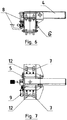
- Fig. 6 presents a side view of the trolley with the lever in the operating position
- Fig. 7 presents a top view of the lock trolley with the lever raised to the operating position.
- wheel lock system presented in Fig. 1 and 2 is integrated with wheel guide 3, in a steel version. After introducing the truck trailer under the unloading ramp wheel lock trolley 2 is manually set along frame 1, using handle 11 to the desired position so that the lock is engaged between the trailer wheels.
- Locking arm 4 in operating position (horizontal) is secured with a ratchet 8, with a simultaneous setting of the position of trolley 2 by introducing pin 10 into the nearest oval hole in frame 1.
Landscapes
- Engineering & Computer Science (AREA)
- Mechanical Engineering (AREA)
- Transportation (AREA)
- Health & Medical Sciences (AREA)
- Public Health (AREA)
- Handcart (AREA)
Description
- The subject of the invention is a wheel lock system applicable to immobilising trucks at a loading ramp. The wheel lock system is a stand-alone device, independent from the vehicle.
Patent literature includes many technical solutions that refer to the issue of immobilisation of trucks that dock at a ramp. The known designs of these devices are correct and they operate in an adequate manner. However, there can be observed certain maintenance issues as well as inconveniences related mainly to a bad condition of surface in the docking location as well as other causes.
Deformed surface may cause issues in the case of guide-based lock devices placed directly on this kind of surface and fixed to it. Surface deformation may have a negative impact on the operation of such locks. Other negative factors may include climate impacts, such as cases when a guide located on the surface is covered with ice and/or snow, as well as impact of dirt, sand, mud and gravel contamination. Guides located on the surface are present, for instance, in patent descriptions no.US8590673 andUS6524053 .
Another inconvenience of the known solutions is the susceptibility to damage the device in the case of an inadvertent start of the truck and exert pressure on the device in locked mode. In such cases, trucks with high powered engines may deform and damage lock components, which may make it impossible to remove the wheel lock or even destroy the device. The patent descriptionUS6773221 may serve as a relevant example here.US2002141852 A1 discloses the preamble of claim 1. - In order to eliminate inconvenient maintenance issues in the known devices, a wheel lock system has been developed, which consists of a frame in the form of a massive beam supported by brackets and a trolley located on this frame with a locking arm installed using a pinned connection in the body. Locking arm in operating position is positioned horizontally and its position is set by a ratchet mechanism. The frame has a line of evenly spaced holes along its axis, which enables setting the trolley in a desired location using an arm locking pin introduced into one of the holes in the frame. Holes in the frame are oval shaped or in a shape approximate to oval.
The lock trolley is equipped with a system of load-bearing rollers: upper, side and lower. These rollers are made of a flexible material and their task is to lead the trolley with its protection against disengagement upwards and sideways. Roller assemblies are installed on springs. - The device is equipped with a ratchet locking system that keeps the locking arm in the position of use. The ratchet locking system with an electrical actuator prevents the deactivation of the wheel lock when the dock gate is not closed. The locking system prevents the opening of the dock gate when the locking arm is in the resting position (vertical).
- The wheel lock system according to the invention is synchronised with a warning lights system and with a dock gate drive according to the known solutions. The wheel lock system is also equipped with a wheel presence sensor so as not to allow the lock to be present outside the truck wheel assembly. Beneficial results of the invention involve obtaining a significant resilience of the lock system to damage resulting from deformation caused by pressure exerted by truck wheels thanks to the application of an assembly of load-bearing, flexible rollers of the lock trolley and oval holes in the frame, which makes it possible to move the pin as the rollers bend. The flexibility of the assembly is additionally provided by placing the roller assemblies on flat springs. Placing the trolley and the frame on brackets so that they are at a similar level to the truck wheel axis effectively protects the device against climate factors and contamination.
An example of the invention is presented in the figures.Fig. 1 presents side view of the wheel lock system in the version coupled with a wheel guide,Fig. 2 presents this system in a top view,Fig. 3 presents a cross-section of the system along the A-A line, where the locking arm is presented both in the operating position (horizontal) and the resting position (vertical),Fig. 4 presents a side view of the lock trolley, whereas the locking arm is in the resting position (vertical),Fig. 5 presents a top view of the lock trolley, wherein the locking arm is in the resting position,Fig. 6 presents a side view of the trolley with the lever in the operating position, whileFig. 7 presents a top view of the lock trolley with the lever raised to the operating position. - The wheel lock system presented in
Fig. 1 and 2 is integrated withwheel guide 3, in a steel version. After introducing the truck trailer under the unloading rampwheel lock trolley 2 is manually set along frame 1, usinghandle 11 to the desired position so that the lock is engaged between the trailer wheels. - Setting
locking arm 4 to the operating position is carried out using thesame handle 11.Locking arm 4 in operating position (horizontal) is secured with aratchet 8, with a simultaneous setting of the position oftrolley 2 by introducingpin 10 into the nearest oval hole in frame 1. - Setting the wheel lock system in the operating position enables the dock gate to be opened, but when the lock is secured using
pin 9 that immobilisesratchet assembly 8. Closing the dock gate releasespin 9, which makes it possible to disengage the lock assembly by puttingarm 4 into vertical position.
Claims (5)
- Wheel lock system including a frame (1) and a moving lock trolley (2), wherein the frame (1) has a line of evenly spaced holes along its axis, characterised in that the lock trolley (2) is equipped with a locking arm (4) attached to the trolley body (2) using a pinned connection and a load-bearing roller assembly (5, 6, 7), a ratchet assembly (8) along with the ratchet lock assembly (9), while the locking arm (4) is equipped with a pin (10) that sets the trolley (2) location in the operating position of the lock, where the frame holes (1) have an oval shape, or have a shape approximate to oval and the load-bearing roller assemblies (5, 6, 7) are made of a flexible material.
- System acc. to claim 1 characterised in that the ratchet lock mechanism (9) is made in a form of a pin, controlled beneficially using an actuator.
- System acc. to claim 1, characterised in that the roller assemblies of the trolley (2) include upper (5), side (6) and lower assembly of rollers (7).
- System acc. to claims 1 or 3, characterised in that the load-bearing rollers (5, 6, 7) are beneficially ball-bearing mounted.
- System acc. to claims 1 or 4, characterised in that the roller assemblies (5, 6, 7) are installed on springs (12).
Applications Claiming Priority (1)
| Application Number | Priority Date | Filing Date | Title |
|---|---|---|---|
| PL426713A PL241544B1 (en) | 2018-08-20 | 2018-08-20 | Wheel lock set |
Publications (2)
| Publication Number | Publication Date |
|---|---|
| EP3613685A1 EP3613685A1 (en) | 2020-02-26 |
| EP3613685B1 true EP3613685B1 (en) | 2021-07-21 |
Family
ID=68240696
Family Applications (1)
| Application Number | Title | Priority Date | Filing Date |
|---|---|---|---|
| EP19460044.1A Active EP3613685B1 (en) | 2018-08-20 | 2019-08-08 | Wheel lock system for immobilising trucks at a loading ramp |
Country Status (2)
| Country | Link |
|---|---|
| EP (1) | EP3613685B1 (en) |
| PL (1) | PL241544B1 (en) |
Cited By (5)
| Publication number | Priority date | Publication date | Assignee | Title |
|---|---|---|---|---|
| US11479217B2 (en) | 2013-11-29 | 2022-10-25 | 9172-9863 Quebec Inc. | Wheel chock and method |
| US11535209B2 (en) | 2017-09-14 | 2022-12-27 | 9172-9863 Québec Inc. | Wheel chock with locking mechanism |
| USD987542S1 (en) | 2021-03-22 | 2023-05-30 | 9172-9863 Québec Inc. | Wheel chock |
| USD995394S1 (en) | 2021-03-22 | 2023-08-15 | 9172-9863 Québec Inc. | Wheel chock |
| US12420748B2 (en) | 2018-11-09 | 2025-09-23 | 9172-9863 Quebec Inc. | Wheel chock handling unit and method |
Family Cites Families (5)
| Publication number | Priority date | Publication date | Assignee | Title |
|---|---|---|---|---|
| US6092970A (en) * | 1998-01-09 | 2000-07-25 | Rite-Hite Holding Corporation | Manually positioned wheel chocking apparatus |
| US6773221B2 (en) | 2001-07-05 | 2004-08-10 | Rite-Hite Holding Corporation | Positive locking mechanism for a wheel-activated vehicle restraint |
| US8590673B2 (en) | 2008-02-05 | 2013-11-26 | Rite-Hite Holding Corporation | Manual wheel chocks with automatic positive locking |
| CA2723636C (en) * | 2009-12-01 | 2014-04-15 | 4Front Engineered Solutions, Inc. | Wheel chocks and associated methods and systems |
| FR2988058B1 (en) * | 2012-03-15 | 2014-10-03 | A Fermetures As | VEHICLE DOCKING DEVICE FOR CARRYING GOODS |
-
2018
- 2018-08-20 PL PL426713A patent/PL241544B1/en unknown
-
2019
- 2019-08-08 EP EP19460044.1A patent/EP3613685B1/en active Active
Non-Patent Citations (1)
| Title |
|---|
| None * |
Cited By (7)
| Publication number | Priority date | Publication date | Assignee | Title |
|---|---|---|---|---|
| US11479217B2 (en) | 2013-11-29 | 2022-10-25 | 9172-9863 Quebec Inc. | Wheel chock and method |
| US11987223B2 (en) | 2013-11-29 | 2024-05-21 | 9172-9863 Quebec Inc. | Wheel chock and method |
| US11535209B2 (en) | 2017-09-14 | 2022-12-27 | 9172-9863 Québec Inc. | Wheel chock with locking mechanism |
| US12005874B2 (en) | 2017-09-14 | 2024-06-11 | 9172-9863 Quebec Inc. | Wheel chock with locking mechanism |
| US12420748B2 (en) | 2018-11-09 | 2025-09-23 | 9172-9863 Quebec Inc. | Wheel chock handling unit and method |
| USD987542S1 (en) | 2021-03-22 | 2023-05-30 | 9172-9863 Québec Inc. | Wheel chock |
| USD995394S1 (en) | 2021-03-22 | 2023-08-15 | 9172-9863 Québec Inc. | Wheel chock |
Also Published As
| Publication number | Publication date |
|---|---|
| PL241544B1 (en) | 2022-10-24 |
| EP3613685A1 (en) | 2020-02-26 |
| PL426713A1 (en) | 2020-02-24 |
Similar Documents
| Publication | Publication Date | Title |
|---|---|---|
| EP3613685B1 (en) | Wheel lock system for immobilising trucks at a loading ramp | |
| EP2552809B1 (en) | Latching mechanisms for removable chocks | |
| US8590674B2 (en) | Chock system | |
| EP0784588B1 (en) | Wheel activated vehicle restraint | |
| US8869948B2 (en) | Wheel chocks and associated methods and systems | |
| US6773221B2 (en) | Positive locking mechanism for a wheel-activated vehicle restraint | |
| RU2683216C2 (en) | Gripper for gripping, moving and depositing pallets | |
| EP3074282B1 (en) | Wheel chock | |
| US6926480B2 (en) | Supplemental restraint for auto-rack railroad car restraint system | |
| US7780383B2 (en) | Locking system for roll-off containers with a positive unlocking mechanism to prevent binding | |
| MX2015000940A (en) | Vehicle restraints with underside catches. | |
| US7985043B2 (en) | Transport trailer | |
| DK2567911T3 (en) | SHIPPING CONTAINER WITH A door locking mechanism AND METHOD FOR CLOSURE OF SUCH CONTAINERS DOORS | |
| US6068440A (en) | Locking mechanism for roll-off hoist | |
| US5758890A (en) | Locking system for a semitrailer chassis and removable container | |
| EP3401251A1 (en) | Guide rail or beam, transfer installation and method for use | |
| EP1764275B1 (en) | Wheel chock for vehicle wheel | |
| US10179615B2 (en) | Apparatus, system, and related methods for holding and maneuvering an industrial vehicle spare tire | |
| KR20170048120A (en) | Loading Dock Locking System | |
| CA2929667C (en) | Auto-rack railroad car vehicle restraint apparatus | |
| JP4796407B2 (en) | Vehicle carrier | |
| JP2007112346A (en) | Sliding type roof carrier | |
| US20170349084A1 (en) | Locking Mechanism For Roll Off Hoist Containers | |
| KR0116022Y1 (en) | Fixing device of spare wheel for a vehicle | |
| JP2000335307A (en) | Automobile loading and unloading method, and loading ramp device in automobile transport vehicle |
Legal Events
| Date | Code | Title | Description |
|---|---|---|---|
| PUAI | Public reference made under article 153(3) epc to a published international application that has entered the european phase |
Free format text: ORIGINAL CODE: 0009012 |
|
| STAA | Information on the status of an ep patent application or granted ep patent |
Free format text: STATUS: THE APPLICATION HAS BEEN PUBLISHED |
|
| AK | Designated contracting states |
Kind code of ref document: A1 Designated state(s): AL AT BE BG CH CY CZ DE DK EE ES FI FR GB GR HR HU IE IS IT LI LT LU LV MC MK MT NL NO PL PT RO RS SE SI SK SM TR |
|
| AX | Request for extension of the european patent |
Extension state: BA ME |
|
| RIN1 | Information on inventor provided before grant (corrected) |
Inventor name: CHAWCHUNOWICZ, LUKASZ |
|
| RIN1 | Information on inventor provided before grant (corrected) |
Inventor name: CHAWCHUNOWICZ, LUKASZ |
|
| RBV | Designated contracting states (corrected) |
Designated state(s): AL AT BE BG CH CY CZ DE DK EE ES FI FR GB GR HR HU IE IS IT LI LT LU LV MC MK MT NL NO PL PT RO RS SE SI SK SM TR |
|
| STAA | Information on the status of an ep patent application or granted ep patent |
Free format text: STATUS: REQUEST FOR EXAMINATION WAS MADE |
|
| 17P | Request for examination filed |
Effective date: 20200731 |
|
| GRAP | Despatch of communication of intention to grant a patent |
Free format text: ORIGINAL CODE: EPIDOSNIGR1 |
|
| STAA | Information on the status of an ep patent application or granted ep patent |
Free format text: STATUS: GRANT OF PATENT IS INTENDED |
|
| INTG | Intention to grant announced |
Effective date: 20201223 |
|
| GRAS | Grant fee paid |
Free format text: ORIGINAL CODE: EPIDOSNIGR3 |
|
| GRAA | (expected) grant |
Free format text: ORIGINAL CODE: 0009210 |
|
| STAA | Information on the status of an ep patent application or granted ep patent |
Free format text: STATUS: THE PATENT HAS BEEN GRANTED |
|
| AK | Designated contracting states |
Kind code of ref document: B1 Designated state(s): AL AT BE BG CH CY CZ DE DK EE ES FI FR GB GR HR HU IE IS IT LI LT LU LV MC MK MT NL NO PL PT RO RS SE SI SK SM TR |
|
| REG | Reference to a national code |
Ref country code: GB Ref legal event code: FG4D |
|
| REG | Reference to a national code |
Ref country code: CH Ref legal event code: EP |
|
| REG | Reference to a national code |
Ref country code: DE Ref legal event code: R096 Ref document number: 602019006296 Country of ref document: DE |
|
| REG | Reference to a national code |
Ref country code: AT Ref legal event code: REF Ref document number: 1412429 Country of ref document: AT Kind code of ref document: T Effective date: 20210815 |
|
| REG | Reference to a national code |
Ref country code: IE Ref legal event code: FG4D |
|
| REG | Reference to a national code |
Ref country code: LT Ref legal event code: MG9D |
|
| REG | Reference to a national code |
Ref country code: NL Ref legal event code: MP Effective date: 20210721 |
|
| REG | Reference to a national code |
Ref country code: AT Ref legal event code: MK05 Ref document number: 1412429 Country of ref document: AT Kind code of ref document: T Effective date: 20210721 |
|
| PG25 | Lapsed in a contracting state [announced via postgrant information from national office to epo] |
Ref country code: ES Free format text: LAPSE BECAUSE OF FAILURE TO SUBMIT A TRANSLATION OF THE DESCRIPTION OR TO PAY THE FEE WITHIN THE PRESCRIBED TIME-LIMIT Effective date: 20210721 Ref country code: RS Free format text: LAPSE BECAUSE OF FAILURE TO SUBMIT A TRANSLATION OF THE DESCRIPTION OR TO PAY THE FEE WITHIN THE PRESCRIBED TIME-LIMIT Effective date: 20210721 Ref country code: SE Free format text: LAPSE BECAUSE OF FAILURE TO SUBMIT A TRANSLATION OF THE DESCRIPTION OR TO PAY THE FEE WITHIN THE PRESCRIBED TIME-LIMIT Effective date: 20210721 Ref country code: HR Free format text: LAPSE BECAUSE OF FAILURE TO SUBMIT A TRANSLATION OF THE DESCRIPTION OR TO PAY THE FEE WITHIN THE PRESCRIBED TIME-LIMIT Effective date: 20210721 Ref country code: FI Free format text: LAPSE BECAUSE OF FAILURE TO SUBMIT A TRANSLATION OF THE DESCRIPTION OR TO PAY THE FEE WITHIN THE PRESCRIBED TIME-LIMIT Effective date: 20210721 Ref country code: PT Free format text: LAPSE BECAUSE OF FAILURE TO SUBMIT A TRANSLATION OF THE DESCRIPTION OR TO PAY THE FEE WITHIN THE PRESCRIBED TIME-LIMIT Effective date: 20211122 Ref country code: NL Free format text: LAPSE BECAUSE OF FAILURE TO SUBMIT A TRANSLATION OF THE DESCRIPTION OR TO PAY THE FEE WITHIN THE PRESCRIBED TIME-LIMIT Effective date: 20210721 Ref country code: NO Free format text: LAPSE BECAUSE OF FAILURE TO SUBMIT A TRANSLATION OF THE DESCRIPTION OR TO PAY THE FEE WITHIN THE PRESCRIBED TIME-LIMIT Effective date: 20211021 Ref country code: LT Free format text: LAPSE BECAUSE OF FAILURE TO SUBMIT A TRANSLATION OF THE DESCRIPTION OR TO PAY THE FEE WITHIN THE PRESCRIBED TIME-LIMIT Effective date: 20210721 Ref country code: BG Free format text: LAPSE BECAUSE OF FAILURE TO SUBMIT A TRANSLATION OF THE DESCRIPTION OR TO PAY THE FEE WITHIN THE PRESCRIBED TIME-LIMIT Effective date: 20211021 Ref country code: AT Free format text: LAPSE BECAUSE OF FAILURE TO SUBMIT A TRANSLATION OF THE DESCRIPTION OR TO PAY THE FEE WITHIN THE PRESCRIBED TIME-LIMIT Effective date: 20210721 |
|
| PG25 | Lapsed in a contracting state [announced via postgrant information from national office to epo] |
Ref country code: PL Free format text: LAPSE BECAUSE OF FAILURE TO SUBMIT A TRANSLATION OF THE DESCRIPTION OR TO PAY THE FEE WITHIN THE PRESCRIBED TIME-LIMIT Effective date: 20210721 Ref country code: LV Free format text: LAPSE BECAUSE OF FAILURE TO SUBMIT A TRANSLATION OF THE DESCRIPTION OR TO PAY THE FEE WITHIN THE PRESCRIBED TIME-LIMIT Effective date: 20210721 Ref country code: GR Free format text: LAPSE BECAUSE OF FAILURE TO SUBMIT A TRANSLATION OF THE DESCRIPTION OR TO PAY THE FEE WITHIN THE PRESCRIBED TIME-LIMIT Effective date: 20211022 |
|
| REG | Reference to a national code |
Ref country code: DE Ref legal event code: R097 Ref document number: 602019006296 Country of ref document: DE Ref country code: BE Ref legal event code: MM Effective date: 20210831 |
|
| PG25 | Lapsed in a contracting state [announced via postgrant information from national office to epo] |
Ref country code: DK Free format text: LAPSE BECAUSE OF FAILURE TO SUBMIT A TRANSLATION OF THE DESCRIPTION OR TO PAY THE FEE WITHIN THE PRESCRIBED TIME-LIMIT Effective date: 20210721 |
|
| PLBE | No opposition filed within time limit |
Free format text: ORIGINAL CODE: 0009261 |
|
| STAA | Information on the status of an ep patent application or granted ep patent |
Free format text: STATUS: NO OPPOSITION FILED WITHIN TIME LIMIT |
|
| PG25 | Lapsed in a contracting state [announced via postgrant information from national office to epo] |
Ref country code: SM Free format text: LAPSE BECAUSE OF FAILURE TO SUBMIT A TRANSLATION OF THE DESCRIPTION OR TO PAY THE FEE WITHIN THE PRESCRIBED TIME-LIMIT Effective date: 20210721 Ref country code: SK Free format text: LAPSE BECAUSE OF FAILURE TO SUBMIT A TRANSLATION OF THE DESCRIPTION OR TO PAY THE FEE WITHIN THE PRESCRIBED TIME-LIMIT Effective date: 20210721 Ref country code: RO Free format text: LAPSE BECAUSE OF FAILURE TO SUBMIT A TRANSLATION OF THE DESCRIPTION OR TO PAY THE FEE WITHIN THE PRESCRIBED TIME-LIMIT Effective date: 20210721 Ref country code: MC Free format text: LAPSE BECAUSE OF FAILURE TO SUBMIT A TRANSLATION OF THE DESCRIPTION OR TO PAY THE FEE WITHIN THE PRESCRIBED TIME-LIMIT Effective date: 20210721 Ref country code: LU Free format text: LAPSE BECAUSE OF NON-PAYMENT OF DUE FEES Effective date: 20210808 Ref country code: EE Free format text: LAPSE BECAUSE OF FAILURE TO SUBMIT A TRANSLATION OF THE DESCRIPTION OR TO PAY THE FEE WITHIN THE PRESCRIBED TIME-LIMIT Effective date: 20210721 Ref country code: CZ Free format text: LAPSE BECAUSE OF FAILURE TO SUBMIT A TRANSLATION OF THE DESCRIPTION OR TO PAY THE FEE WITHIN THE PRESCRIBED TIME-LIMIT Effective date: 20210721 Ref country code: AL Free format text: LAPSE BECAUSE OF FAILURE TO SUBMIT A TRANSLATION OF THE DESCRIPTION OR TO PAY THE FEE WITHIN THE PRESCRIBED TIME-LIMIT Effective date: 20210721 |
|
| 26N | No opposition filed |
Effective date: 20220422 |
|
| PG25 | Lapsed in a contracting state [announced via postgrant information from national office to epo] |
Ref country code: IT Free format text: LAPSE BECAUSE OF FAILURE TO SUBMIT A TRANSLATION OF THE DESCRIPTION OR TO PAY THE FEE WITHIN THE PRESCRIBED TIME-LIMIT Effective date: 20210721 Ref country code: IE Free format text: LAPSE BECAUSE OF NON-PAYMENT OF DUE FEES Effective date: 20210808 Ref country code: BE Free format text: LAPSE BECAUSE OF NON-PAYMENT OF DUE FEES Effective date: 20210831 |
|
| REG | Reference to a national code |
Ref country code: CH Ref legal event code: PL |
|
| PG25 | Lapsed in a contracting state [announced via postgrant information from national office to epo] |
Ref country code: LI Free format text: LAPSE BECAUSE OF NON-PAYMENT OF DUE FEES Effective date: 20220831 Ref country code: CH Free format text: LAPSE BECAUSE OF NON-PAYMENT OF DUE FEES Effective date: 20220831 |
|
| PG25 | Lapsed in a contracting state [announced via postgrant information from national office to epo] |
Ref country code: CY Free format text: LAPSE BECAUSE OF FAILURE TO SUBMIT A TRANSLATION OF THE DESCRIPTION OR TO PAY THE FEE WITHIN THE PRESCRIBED TIME-LIMIT Effective date: 20210721 |
|
| PG25 | Lapsed in a contracting state [announced via postgrant information from national office to epo] |
Ref country code: HU Free format text: LAPSE BECAUSE OF FAILURE TO SUBMIT A TRANSLATION OF THE DESCRIPTION OR TO PAY THE FEE WITHIN THE PRESCRIBED TIME-LIMIT; INVALID AB INITIO Effective date: 20190808 |
|
| GBPC | Gb: european patent ceased through non-payment of renewal fee |
Effective date: 20230808 |
|
| PG25 | Lapsed in a contracting state [announced via postgrant information from national office to epo] |
Ref country code: MK Free format text: LAPSE BECAUSE OF FAILURE TO SUBMIT A TRANSLATION OF THE DESCRIPTION OR TO PAY THE FEE WITHIN THE PRESCRIBED TIME-LIMIT Effective date: 20210721 |
|
| PG25 | Lapsed in a contracting state [announced via postgrant information from national office to epo] |
Ref country code: TR Free format text: LAPSE BECAUSE OF FAILURE TO SUBMIT A TRANSLATION OF THE DESCRIPTION OR TO PAY THE FEE WITHIN THE PRESCRIBED TIME-LIMIT Effective date: 20210721 |
|
| PG25 | Lapsed in a contracting state [announced via postgrant information from national office to epo] |
Ref country code: GB Free format text: LAPSE BECAUSE OF NON-PAYMENT OF DUE FEES Effective date: 20230808 |
|
| PG25 | Lapsed in a contracting state [announced via postgrant information from national office to epo] |
Ref country code: GB Free format text: LAPSE BECAUSE OF NON-PAYMENT OF DUE FEES Effective date: 20230808 |
|
| PG25 | Lapsed in a contracting state [announced via postgrant information from national office to epo] |
Ref country code: MT Free format text: LAPSE BECAUSE OF FAILURE TO SUBMIT A TRANSLATION OF THE DESCRIPTION OR TO PAY THE FEE WITHIN THE PRESCRIBED TIME-LIMIT Effective date: 20210721 |
|
| PGFP | Annual fee paid to national office [announced via postgrant information from national office to epo] |
Ref country code: FR Payment date: 20250120 Year of fee payment: 7 |
|
| PGFP | Annual fee paid to national office [announced via postgrant information from national office to epo] |
Ref country code: DE Payment date: 20260123 Year of fee payment: 7 |