EP3613649A1 - Automobile power steering sensor - Google Patents
Automobile power steering sensor Download PDFInfo
- Publication number
- EP3613649A1 EP3613649A1 EP18787669.3A EP18787669A EP3613649A1 EP 3613649 A1 EP3613649 A1 EP 3613649A1 EP 18787669 A EP18787669 A EP 18787669A EP 3613649 A1 EP3613649 A1 EP 3613649A1
- Authority
- EP
- European Patent Office
- Prior art keywords
- upper housing
- power steering
- automobile power
- input shaft
- housing
- Prior art date
- Legal status (The legal status is an assumption and is not a legal conclusion. Google has not performed a legal analysis and makes no representation as to the accuracy of the status listed.)
- Granted
Links
Images


Classifications
-
- B—PERFORMING OPERATIONS; TRANSPORTING
- B62—LAND VEHICLES FOR TRAVELLING OTHERWISE THAN ON RAILS
- B62D—MOTOR VEHICLES; TRAILERS
- B62D15/00—Steering not otherwise provided for
- B62D15/02—Steering position indicators ; Steering position determination; Steering aids
- B62D15/021—Determination of steering angle
- B62D15/0215—Determination of steering angle by measuring on the steering column
-
- B—PERFORMING OPERATIONS; TRANSPORTING
- B62—LAND VEHICLES FOR TRAVELLING OTHERWISE THAN ON RAILS
- B62D—MOTOR VEHICLES; TRAILERS
- B62D5/00—Power-assisted or power-driven steering
- B62D5/04—Power-assisted or power-driven steering electrical, e.g. using an electric servo-motor connected to, or forming part of, the steering gear
-
- B—PERFORMING OPERATIONS; TRANSPORTING
- B62—LAND VEHICLES FOR TRAVELLING OTHERWISE THAN ON RAILS
- B62D—MOTOR VEHICLES; TRAILERS
- B62D6/00—Arrangements for automatically controlling steering depending on driving conditions sensed and responded to, e.g. control circuits
- B62D6/08—Arrangements for automatically controlling steering depending on driving conditions sensed and responded to, e.g. control circuits responsive only to driver input torque
- B62D6/10—Arrangements for automatically controlling steering depending on driving conditions sensed and responded to, e.g. control circuits responsive only to driver input torque characterised by means for sensing or determining torque
-
- G—PHYSICS
- G01—MEASURING; TESTING
- G01L—MEASURING FORCE, STRESS, TORQUE, WORK, MECHANICAL POWER, MECHANICAL EFFICIENCY, OR FLUID PRESSURE
- G01L5/00—Apparatus for, or methods of, measuring force, work, mechanical power, or torque, specially adapted for specific purposes
- G01L5/22—Apparatus for, or methods of, measuring force, work, mechanical power, or torque, specially adapted for specific purposes for measuring the force applied to control members, e.g. control members of vehicles, triggers
- G01L5/221—Apparatus for, or methods of, measuring force, work, mechanical power, or torque, specially adapted for specific purposes for measuring the force applied to control members, e.g. control members of vehicles, triggers to steering wheels, e.g. for power assisted steering
Definitions
- the present disclosure relates to the field of automobile components, and in particular to an automobile power steering sensor.
- the term “automobile power steering” refers to increasing external force to overcome the steering resistance such that a driver can implement the steering operation by less force, and it also refers to as “power steering”.
- the automobile power steering simplifies and easies the driving operation, enables the automobile to response more quickly, and improves the safety thereof, thus obtaining extensive attention.
- An automobile power steering sensor detects the magnitude and direction of torque or rotation angle of the steering wheel produced during the steering operation of the driver, converts the necessary information into digital signals, inputs the digital signals into a control unit, which, in turn, calculates the signals and acquires a moment corresponding to the driving condition, and issues instructions to drive an electromotor to work. Then the output torque of the electromotor implements power by a gearing device. Therefore, the sensor is one of the most important components of an automobile power steering system.
- PCB assembly is connected securely with the upper housing, PCB plate is clamped between the lower housing and the input shaft rotor, and the upper housing and the lower housing are connected by laser welding, features with complex processes.
- the rotor is manufactured by plastic injection molding, and connected with the input shaft by way of laser welding, which often results in problems such as inaccurate positioning during securing and motion, and complex processes.
- the present disclosure aims to provide an automobile power steering sensor, which changes the structure of the housing, having it integrated with the structural feature of sliding bearing, thereby altering the assembly relationship of the sensor housing and the input and output shaft rotors, simplifying the mounting process of the sensor itself, and at the same time, under the circumstances that ambient temperature changes and wearing exists, keeping the PCB steady, and keeping the sensor and the input shaft concentric all along.
- an automobile power steering sensor comprising an upper housing, a lower housing, an input shaft rotor, a PCB assembly, and an output shaft rotor, wherein the input shaft rotor is mounted on an input shaft of an automobile power steering apparatus and sleeved on an upper part of the upper housing, the PCB assembly is mounted on a lower part of the upper housing, and the upper housing and the lower housing are securely connected, fixing the PCB assembly in a space formed by the upper housing and the lower housing.
- the upper housing is sleeved on the input shaft of the automobile power steering apparatus, and the output shaft rotor is mounted on the output shaft of the automobile power steering apparatus.
- the input shaft rotor and the input shaft rotate coaxially at the same speed
- the output shaft rotor and the output shaft rotate coaxially at the same speed
- the upper housing keeps concentric and coaxial with the input shaft rotor.
- a mounting part is provided within the upper housing, a sliding bearing structure is integrated on the mounting part; the sliding bearing structure is annular and provided in the middle of the upper housing; the input shaft rotor is sleeved upon the sliding bearing of the upper housing, and the input shaft rotor and the upper housing are provided coaxially and concentrically.
- the sliding bearing comprises at least one support part and at least one elastic part, wherein the support part and the elastic part are provided at intervals.
- the sliding bearing structure comprises 3 groups of the support parts and the elastic parts, wherein the support parts and the elastic parts are completely the same respectively, and two equilateral triangles with the same center are obtained by connecting the centers of the support parts and the elastic parts respectively.
- the support part comprises a first surface and a second surface parallel to each other, wherein a convex plate is provided at the end of the first surface, which protrudes along the radial direction of the upper housing and far away from the shaft center; a convex column is provided on the convex plate along the direction parallel to the axial direction of the upper housing, wherein the second surface is connected with the convex plate, and the first surface is higher than the second surface.
- the elastic part is of a trapezoidal structure, and a groove is provided between the elastic part and the support part; a projection is provided on the free end of the elastic part along the radial direction of the upper housing and toward the shaft center thereof; a hollow slot is provided on the surface of the projection toward the upper housing; and a hollow structure is also provided within the elastic part.
- the groove provided between the elastic part and the support part is U-shaped.
- the mounting part of the upper housing extends downward through the upper housing, and the PCB assembly is sleeved annularly on the lower end of the mounting part of the upper housing.
- the structural feature of the outer edge of the lower housing corresponding to the upper housing extends upwards, and upon being assembled, the outer wall of the lower housing wraps the structure on the upper housing.
- the upper housing and the lower housing are connected securely by way of snapping.
- the upper housing is provided with a hook structure
- the lower housing is provided with a clip slot structure.
- the hook structure of the upper housing is snapped into the clip slot structure of the lower housing, thereby connecting securely the upper housing and the lower housing.
- the input shaft rotor 1 is mounted upon an input shaft 6 of an automobile power steering apparatus and sleeved on an upper part of the upper housing 2; the PCB assembly 3 is mounted upon the lower part of the upper housing 2, and the upper housing 2 and the lower housing 4 are securely connected, fixing the PCB assembly 3 in a space formed therebetween.
- the upper housing 2 is sleeved on the input shaft 6 of the automobile power steering apparatus, and the output shaft rotor 5 is mounted on the output shaft 7 of the automobile power steering apparatus.
- the input shaft rotor 1 and the input shaft 6 rotate coaxially at the same speed
- the output shaft rotor 5 and the output shaft 7 rotate coaxially at the same speed
- the upper housing 2 and the input shaft rotor 1 keep concentric and coaxial with each other.
- the embodiment realizes not only that the input shaft rotor 1 is independent of the whole housing, but also that the structure of the input shaft rotor is simplified, hence it guarantees the axial positioning of the upper housing equally, without need to fit with a gearing part, nor to add a circle steel wire spring to offset the gap caused by the friction and wearing in the direction of radial with the upper housing during the rotation of the input shaft rotor.
- FIG.3 it is a structural view of an upper housing of an automobile power steering sensor according to one preferred embodiment of the present disclosure. It can be seen therefrom that preferably, in the embodiment, a mounting part 20 is provided within the upper housing 2, and a sliding bearing structure 200 is integrated on the upper part of the mounting part 20.
- the sliding bearing structure 200 is annular and provided in the middle of the upper housing 2.
- the upper housing 2 is sleeved onto the input shaft 6 of the automobile power steering apparatus, and the input shaft rotor 1 is also sleeved onto the input shaft 6, then is sleeved upon the sliding bearing 200 of the upper housing 2, such that when the automobile power steering apparatus operates, the upper housing 2 and the input shaft rotor 1 is able to keep coaxial and concentric all the time.
- the sliding bearing 200 integrated on the upper housing 2 in this embodiment comprises support parts 201 and elastic parts 202, wherein the support parts 201 and the elastic parts 202 are provided at intervals, that is, each elastic part 202 is provided between two support parts 201 while each support part 201 is also provided between two elastic parts 202.
- the support parts 201 are able to supply supporting force to the elastic parts 202, thereby to a certain extent, preventing the elastic parts 202 from damage caused by the effect of the external stress.
- the support part 201 provided in this embodiment comprises two arc-shaped surfaces parallel to each other, that is, a first surface 203 and a second surface 204, wherein a convex plate is provided at the end of the first surface 203, which protrudes from the first surface 203 along the radial direction of the upper housing 2 and far away from the shaft center. Moreover, a convex column is provided on the convex plate along the direction parallel to the axial direction of the upper housing 2, wherein the second surface 204 is connected with the convex plate, and the first surface 203 is higher than the second surface 204.
- the convex column contact directly with the input shaft rotor 1, thereby avoiding the damage of the upper housing 2 resulted from the friction produced by the rotation of the input shaft rotor 1 during the operation of the power steering apparatus; meanwhile, in the present embodiment, the input shaft rotor 1 and the sliding bearing structure 200 fit with each other.
- the second surface 204 is provided to connect with two adjacent convex plates, so as to supply the whole sliding bearing structure 200 with support force, which prevents effectively the damage of the sliding bearing structure from the stress produced when the input shaft rotor 1 and the sliding bearing structure 200 assemble fitting with each other.
- the elastic parts 201 of the sliding bearing structure 200 are of a trapezoidal structure, wherein there is also provided with a groove between an elastic part 202 and a support part 201.
- a projection is provided on the free end of the elastic part 202 along the radial direction of the upper housing 2 and toward the shaft center thereof.
- On the surface of the projection toward the upper housing 2 is provided a hollow slot, while there is also a hollow structure within the elastic part 202.
- the projection structure of the elastic part 202 makes it possible that the upper housing 2 and the input shaft 6 assume in slight interference fit, and when the automobile power steering apparatus operates, the groove, the hollow slot and the hollow structure inside cooperate to enable the elastic part 202 to have a certain resilience force like a leaf spring, thus the upper housing 2 is capable of deforming itself to offset the fit clearance resulted from the mutual wearing of the input shaft rotor 1 and the upper housing 2, such that the input shaft rotor 1 and the upper housing 2 can keep coaxial and concentric all along.
- the sliding bearing structure 300 in the present embodiment comprises 3 groups of the support parts 201 and the elastic parts 202, wherein the support parts 201 and the elastic parts 202 are completely the same respectively, and two equilateral triangles with the same center can be obtained by connecting the centers of the support parts 201 and the elastic parts 202 respectively.
- the above-mentioned design enables the whole sliding bearing structure 200 to be steadier and improves the endurance to the stress produced during the assembly and operation of the automobile power steering sensor, thereby reducing the damage rate of the upper housing 2 effectively.
- the groove provided between the elastic part 202 and the support part 201 is U-shaped. This configuration improves the bearing capacity of the elastic part.
- the mounting part 20 of the upper housing 2 extends downward through the upper housing 2, and the PCB assembly 3 is sleeved annularly on the lower end of the mounting part of the upper housing 2, so as to keep the PCB assembly 3 and the upper housing 2 coaxial and concentric all the time.
- the structural feature of the outer edge of the lower housing 4 corresponding to the upper housing 2 extends upwards, and upon being assembled, the outer wall of the lower housing 4 wraps the structure on the upper housing 2.
- This design is also able to protect the structure on the upper housing 2 from the external force produced during the assembly and the operation of the automobile power steering apparatus, or from other damages.
- the upper housing 2 is provided with a hook structure
- the lower housing 4 is provided with a clip slot structure.
- the hook structure of the upper housing 2 is snapped into the clip slot structure of the lower housing 4, thus the upper housing 2 and the lower housing 4 is connected securely by way of snapping.
- the input shaft rotor has a simplified structure and improved precision, is independent of the whole housing, and guarantees the concentricity of the input shaft rotor and the input shaft; meanwhile, due to that during rotation, the input shaft rotor does not have friction or wearing with the upper housing in the radial direction, it is no need to add a circle steel wire spring to offset the gap caused by the friction or wearing.
- the axial positioning of the upper housing can be guaranteed equally, thus there is no need any more to fit with gear parts; furthermore, the sliding bearing structure integrated on the upper housing enables the housing and the input shaft to keep in slight interference fit, and is also able to deform its own structure to offset the gap caused by wearing; finally the present disclosure uses the way of snapping connection to overcome the problem of complex mounting process of the upper and lower housings, and to facilitate the later dissembling and maintenance thereof, or the like.
Landscapes
- Engineering & Computer Science (AREA)
- Chemical & Material Sciences (AREA)
- Combustion & Propulsion (AREA)
- Transportation (AREA)
- Mechanical Engineering (AREA)
- Physics & Mathematics (AREA)
- General Physics & Mathematics (AREA)
- Power Steering Mechanism (AREA)
- Steering Controls (AREA)
Abstract
Description
- The present disclosure relates to the field of automobile components, and in particular to an automobile power steering sensor.
- The term "automobile power steering" refers to increasing external force to overcome the steering resistance such that a driver can implement the steering operation by less force, and it also refers to as "power steering". The automobile power steering simplifies and easies the driving operation, enables the automobile to response more quickly, and improves the safety thereof, thus obtaining extensive attention. An automobile power steering sensor detects the magnitude and direction of torque or rotation angle of the steering wheel produced during the steering operation of the driver, converts the necessary information into digital signals, inputs the digital signals into a control unit, which, in turn, calculates the signals and acquires a moment corresponding to the driving condition, and issues instructions to drive an electromotor to work. Then the output torque of the electromotor implements power by a gearing device. Therefore, the sensor is one of the most important components of an automobile power steering system.
- In the prior art of the automobile power steering sensor, the radial positioning of an input shaft rotor need to rely on an upper housing, and match with its installation. However, during rotation, the input shaft rotor might have friction with the upper housing, which results in the wearing of the former. In view of this, it is necessary to additionally embed a circle steel wire spring within the rotor, such that there is always an outwardly-supporting force which could offset the gap caused by the wearing of the input shaft rotor. In the axial direction, the input shaft rotor is welded with a gear, such that the upper housing is fixed relatively in the axial direction. The technical solution that PCB assembly is connected securely with the upper housing, PCB plate is clamped between the lower housing and the input shaft rotor, and the upper housing and the lower housing are connected by laser welding, features with complex processes. Besides, the rotor is manufactured by plastic injection molding, and connected with the input shaft by way of laser welding, which often results in problems such as inaccurate positioning during securing and motion, and complex processes.
- The present disclosure aims to provide an automobile power steering sensor, which changes the structure of the housing, having it integrated with the structural feature of sliding bearing, thereby altering the assembly relationship of the sensor housing and the input and output shaft rotors, simplifying the mounting process of the sensor itself, and at the same time, under the circumstances that ambient temperature changes and wearing exists, keeping the PCB steady, and keeping the sensor and the input shaft concentric all along.
- Particularly, the present disclosure provides an automobile power steering sensor, comprising an upper housing, a lower housing, an input shaft rotor, a PCB assembly, and an output shaft rotor, wherein the input shaft rotor is mounted on an input shaft of an automobile power steering apparatus and sleeved on an upper part of the upper housing, the PCB assembly is mounted on a lower part of the upper housing, and the upper housing and the lower housing are securely connected, fixing the PCB assembly in a space formed by the upper housing and the lower housing. The upper housing is sleeved on the input shaft of the automobile power steering apparatus, and the output shaft rotor is mounted on the output shaft of the automobile power steering apparatus. When the automobile power steering apparatus operates, the input shaft rotor and the input shaft rotate coaxially at the same speed, the output shaft rotor and the output shaft rotate coaxially at the same speed, and the upper housing keeps concentric and coaxial with the input shaft rotor.
- Preferably, a mounting part is provided within the upper housing, a sliding bearing structure is integrated on the mounting part; the sliding bearing structure is annular and provided in the middle of the upper housing; the input shaft rotor is sleeved upon the sliding bearing of the upper housing, and the input shaft rotor and the upper housing are provided coaxially and concentrically.
- Preferably, the sliding bearing comprises at least one support part and at least one elastic part, wherein the support part and the elastic part are provided at intervals.
- Preferably, the sliding bearing structure comprises 3 groups of the support parts and the elastic parts, wherein the support parts and the elastic parts are completely the same respectively, and two equilateral triangles with the same center are obtained by connecting the centers of the support parts and the elastic parts respectively.
- Preferably, the support part comprises a first surface and a second surface parallel to each other, wherein a convex plate is provided at the end of the first surface, which protrudes along the radial direction of the upper housing and far away from the shaft center; a convex column is provided on the convex plate along the direction parallel to the axial direction of the upper housing, wherein the second surface is connected with the convex plate, and the first surface is higher than the second surface.
- Preferably, the elastic part is of a trapezoidal structure, and a groove is provided between the elastic part and the support part; a projection is provided on the free end of the elastic part along the radial direction of the upper housing and toward the shaft center thereof; a hollow slot is provided on the surface of the projection toward the upper housing; and a hollow structure is also provided within the elastic part.
- Preferably, the groove provided between the elastic part and the support part is U-shaped.
- Preferably, the mounting part of the upper housing extends downward through the upper housing, and the PCB assembly is sleeved annularly on the lower end of the mounting part of the upper housing.
- Preferably, the structural feature of the outer edge of the lower housing corresponding to the upper housing extends upwards, and upon being assembled, the outer wall of the lower housing wraps the structure on the upper housing.
- Preferably, the upper housing and the lower housing are connected securely by way of snapping.
- Preferably, the upper housing is provided with a hook structure, and correspondingly, the lower housing is provided with a clip slot structure. During assembly, the hook structure of the upper housing is snapped into the clip slot structure of the lower housing, thereby connecting securely the upper housing and the lower housing.
- Comparing with the prior art, the technical advantages of the present disclosure lie in:
- 1) the input shaft rotor has a simplified structure and improved precision, is independent of the whole housing, and guarantees the concentricity of the input shaft rotor and the input shaft;
- 2) due to that during rotation, the input shaft rotor does not have friction or wearing with the upper housing in the radial direction, it is no need to add a circle steel wire spring to offset the gap caused by the friction or wearing;
- 3) in the axial direction of the sensor, due to that the input shaft rotor presses directly on the upper housing, the axial positioning of the upper housing can be guaranteed equally, thus there is no need any more to fit with gear parts;
- 4) the sliding bearing structure integrated on the upper housing enables the housing and the input shaft to keep in slight interference fit, and is also able to deform its own structure to offset the gap caused by wearing;
- 5) it uses the way of snapping connection to overcome the problem of complex mounting process of the upper and lower housings, and to facilitate the later dissembling and maintenance thereof, or the like.
-
-
Fig.1 is a structural view of an automobile power steering sensor according to one preferred embodiment of the present disclosure. -
Fig.2 is a sectional view of an automobile power steering sensor according to one preferred embodiment of the present disclosure. -
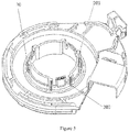
Fig.3 is a structural view of an upper housing of an automobile power steering sensor according to one preferred embodiment of the present disclosure. -
- 1- input shaft rotor,
- 2-upper housing; 20-sliding bearing; 200-sliding bearing structure; 201-support part; 202-elastic part,
- 3- PCB assembly,
- 4-lower housing,
- 5-output shaft rotor,
- 6-input shaft,
- 7-output shaft.
- Hereinafter, a detailed description will be given for the technical advantages of the present disclosure in conjunction with the drawings and specific embodiments.
- With reference to
Fig.1 , it is a structural view of an automobile power steering sensor according to one preferred embodiment of the present disclosure. It can be seen from this drawing that the automobile power steering sensor provided by the present embodiment comprises anupper housing 2, alower housing 4, aninput shaft rotor 1, aPCB assembly 3, and anoutput shaft rotor 5. - Further referring to
Fig.2 , it can be seen therefrom that in the present embodiment, during assembly, theinput shaft rotor 1 is mounted upon aninput shaft 6 of an automobile power steering apparatus and sleeved on an upper part of theupper housing 2; thePCB assembly 3 is mounted upon the lower part of theupper housing 2, and theupper housing 2 and thelower housing 4 are securely connected, fixing thePCB assembly 3 in a space formed therebetween. Theupper housing 2 is sleeved on theinput shaft 6 of the automobile power steering apparatus, and theoutput shaft rotor 5 is mounted on theoutput shaft 7 of the automobile power steering apparatus. When the automobile power steering apparatus operates, theinput shaft rotor 1 and theinput shaft 6 rotate coaxially at the same speed, theoutput shaft rotor 5 and theoutput shaft 7 rotate coaxially at the same speed, and theupper housing 2 and theinput shaft rotor 1 keep concentric and coaxial with each other. In view of the aforementioned configuration, the embodiment realizes not only that theinput shaft rotor 1 is independent of the whole housing, but also that the structure of the input shaft rotor is simplified, hence it guarantees the axial positioning of the upper housing equally, without need to fit with a gearing part, nor to add a circle steel wire spring to offset the gap caused by the friction and wearing in the direction of radial with the upper housing during the rotation of the input shaft rotor. - Meanwhile, referring to
Fig.3 , it is a structural view of an upper housing of an automobile power steering sensor according to one preferred embodiment of the present disclosure. It can be seen therefrom that preferably, in the embodiment, amounting part 20 is provided within theupper housing 2, and a sliding bearing structure 200 is integrated on the upper part of themounting part 20. The sliding bearing structure 200 is annular and provided in the middle of theupper housing 2. Referring toFig.2 , it can be seen that during the assembly of the automobile power steering sensor, first, theupper housing 2 is sleeved onto theinput shaft 6 of the automobile power steering apparatus, and theinput shaft rotor 1 is also sleeved onto theinput shaft 6, then is sleeved upon the sliding bearing 200 of theupper housing 2, such that when the automobile power steering apparatus operates, theupper housing 2 and theinput shaft rotor 1 is able to keep coaxial and concentric all the time. - Further referring to
Fig.3 , it can be seen therefrom that the sliding bearing 200 integrated on theupper housing 2 in this embodiment comprisessupport parts 201 andelastic parts 202, wherein thesupport parts 201 and theelastic parts 202 are provided at intervals, that is, eachelastic part 202 is provided between twosupport parts 201 while eachsupport part 201 is also provided between twoelastic parts 202. In view of the aforementioned configuration, when theelastic parts 202 receives the effect of the external stress, thesupport parts 201 are able to supply supporting force to theelastic parts 202, thereby to a certain extent, preventing theelastic parts 202 from damage caused by the effect of the external stress. - Further referring to
Fig.3 , it can be seen therefrom that thesupport part 201 provided in this embodiment comprises two arc-shaped surfaces parallel to each other, that is, a first surface 203 and a second surface 204, wherein a convex plate is provided at the end of the first surface 203, which protrudes from the first surface 203 along the radial direction of theupper housing 2 and far away from the shaft center. Moreover, a convex column is provided on the convex plate along the direction parallel to the axial direction of theupper housing 2, wherein the second surface 204 is connected with the convex plate, and the first surface 203 is higher than the second surface 204. In view of the aforementioned configuration, when theinput shaft rotor 1 is sleeved into the sliding bearing structure 200, the convex column contact directly with theinput shaft rotor 1, thereby avoiding the damage of theupper housing 2 resulted from the friction produced by the rotation of theinput shaft rotor 1 during the operation of the power steering apparatus; meanwhile, in the present embodiment, theinput shaft rotor 1 and the sliding bearing structure 200 fit with each other. Hence the second surface 204 is provided to connect with two adjacent convex plates, so as to supply the whole sliding bearing structure 200 with support force, which prevents effectively the damage of the sliding bearing structure from the stress produced when theinput shaft rotor 1 and the sliding bearing structure 200 assemble fitting with each other. - Furthermore, preferably, with reference to
Fig.3 , in the present embodiment, theelastic parts 201 of the sliding bearing structure 200 are of a trapezoidal structure, wherein there is also provided with a groove between anelastic part 202 and asupport part 201. Besides, a projection is provided on the free end of theelastic part 202 along the radial direction of theupper housing 2 and toward the shaft center thereof. On the surface of the projection toward theupper housing 2 is provided a hollow slot, while there is also a hollow structure within theelastic part 202. The reason for using the aforementioned configuration in the present embodiment is that the projection structure of theelastic part 202 makes it possible that theupper housing 2 and theinput shaft 6 assume in slight interference fit, and when the automobile power steering apparatus operates, the groove, the hollow slot and the hollow structure inside cooperate to enable theelastic part 202 to have a certain resilience force like a leaf spring, thus theupper housing 2 is capable of deforming itself to offset the fit clearance resulted from the mutual wearing of theinput shaft rotor 1 and theupper housing 2, such that theinput shaft rotor 1 and theupper housing 2 can keep coaxial and concentric all along. - Preferably, as shown in
Fig.3 , the sliding bearing structure 300 in the present embodiment comprises 3 groups of thesupport parts 201 and theelastic parts 202, wherein thesupport parts 201 and theelastic parts 202 are completely the same respectively, and two equilateral triangles with the same center can be obtained by connecting the centers of thesupport parts 201 and theelastic parts 202 respectively. The above-mentioned design enables the whole sliding bearing structure 200 to be steadier and improves the endurance to the stress produced during the assembly and operation of the automobile power steering sensor, thereby reducing the damage rate of theupper housing 2 effectively. - Referring to
Fig.3 , more preferably, the groove provided between theelastic part 202 and thesupport part 201 is U-shaped. This configuration improves the bearing capacity of the elastic part. - Further preferably, referring to
Fig.2 , the mountingpart 20 of theupper housing 2 extends downward through theupper housing 2, and thePCB assembly 3 is sleeved annularly on the lower end of the mounting part of theupper housing 2, so as to keep thePCB assembly 3 and theupper housing 2 coaxial and concentric all the time. - Further preferably, referring to
Fig.1 , the structural feature of the outer edge of thelower housing 4 corresponding to theupper housing 2 extends upwards, and upon being assembled, the outer wall of thelower housing 4 wraps the structure on theupper housing 2. This design is also able to protect the structure on theupper housing 2 from the external force produced during the assembly and the operation of the automobile power steering apparatus, or from other damages. - More preferably, in this embodiment, the
upper housing 2 is provided with a hook structure, and correspondingly, thelower housing 4 is provided with a clip slot structure. During assembly, the hook structure of theupper housing 2 is snapped into the clip slot structure of thelower housing 4, thus theupper housing 2 and thelower housing 4 is connected securely by way of snapping. This design overcomes the problem of complex mounting process of the upper and lower housings, and facilitates the later dissembling and maintenance thereof, and the like. - In summary, in the present disclosure, the input shaft rotor has a simplified structure and improved precision, is independent of the whole housing, and guarantees the concentricity of the input shaft rotor and the input shaft; meanwhile, due to that during rotation, the input shaft rotor does not have friction or wearing with the upper housing in the radial direction, it is no need to add a circle steel wire spring to offset the gap caused by the friction or wearing. Besides, in the axial direction of the sensor, due to that the input shaft rotor presses directly on the upper housing, the axial positioning of the upper housing can be guaranteed equally, thus there is no need any more to fit with gear parts; furthermore, the sliding bearing structure integrated on the upper housing enables the housing and the input shaft to keep in slight interference fit, and is also able to deform its own structure to offset the gap caused by wearing; finally the present disclosure uses the way of snapping connection to overcome the problem of complex mounting process of the upper and lower housings, and to facilitate the later dissembling and maintenance thereof, or the like.
- It should be noted that the embodiments of the present disclosure are of good operability, but not for constituting any limitation to the protection scope thereof. A person skilled in the art can make alterations or modifications to the embodiments by the aforementioned technical contents, to form an equivalent and effective embodiment. Without departing from the technical solutions of the present disclosure, any amendments, equivalent changes and modifications to the above-mentioned embodiments based on the technical essence of the present disclosure, shall fall within the scope defined by the technical solutions of the present disclosure.
Claims (11)
- An automobile power steering sensor, comprising an upper housing, a lower housing, an input shaft rotor, a PCB assembly, and an output shaft rotor, wherein
the input shaft rotor is mounted on an input shaft of an automobile power steering apparatus and sleeved on an upper part of the upper housing,
the PCB assembly is mounted on a lower part of the upper housing,
the upper housing and the lower housing are securely connected, fixing the PCB assembly in a space formed by the upper housing and the lower housing,
the upper housing is sleeved on the input shaft of the automobile power steering apparatus,
the output shaft rotor is mounted on the output shaft of the automobile power steering apparatus, and
when the automobile power steering apparatus operates, the input shaft rotor and the input shaft rotate coaxially at the same speed, the output shaft rotor and the output shaft rotate coaxially at the same speed, and the upper housing keeps concentric and coaxial with the input shaft rotor. - The automobile power steering sensor according to Claim 1, wherein
a mounting part is provided within the upper housing, a sliding bearing structure is integrated on the mounting part, the sliding bearing structure is annular and provided in the middle of the upper housing, the input shaft rotor is sleeved on the sliding bearing of the upper housing, and the input shaft rotor and the upper housing are provided coaxially and concentrically. - The automobile power steering sensor according to Claim 2, wherein
the sliding bearing comprises at least one support part and at least one elastic part, and the support part and the elastic part are provided at intervals. - The automobile power steering sensor according to Claim 3, wherein
the sliding bearing structure comprises 3 groups of the support parts and the elastic parts, wherein the support parts and the elastic parts are completely the same respectively, and two equilateral triangles with the same center are obtained by connecting the centers of the support parts and the elastic parts respectively. - The automobile power steering sensor according to Claim 3, wherein
the support part comprises a first surface and a second surface parallel to each other,
a convex plate is provided at the end of the first surface, which protrudes along the radial direction of the upper housing and far away from the shaft center;
a convex column is provided on the convex plate along the direction parallel to the axial direction of the upper housing,
the second surface is connected with the convex plate, and
the first surface is higher than the second surface. - The automobile power steering sensor according to Claim 3, wherein
the elastic part is of a trapezoidal structure,
a groove is provided between the elastic part and the support part;
a projection is provided on the free end of the elastic part along the radial direction of the upper housing and toward the shaft center thereof,
a hollow slot is provided on the surface of the projection toward the upper housing, and
a hollow structure is also provided within the elastic part. - The automobile power steering sensor according to Claim 6, wherein
the groove provided between the elastic part and the support part is U-shaped. - The automobile power steering sensor according to Claim 1, wherein
the mounting part of the upper housing extends downward through the upper housing, and the PCB assembly is sleeved annularly on the lower end of the mounting part of the upper housing. - The automobile power steering sensor according to Claim 1, wherein
the structural feature of the outer edge of the lower housing corresponding to the upper housing extends upwards, and upon being assembled, the outer wall of the lower housing wraps the structure on the upper housing. - The automobile power steering sensor according to Claim 1, wherein
the upper housing and the lower housing are connected securely by way of snapping. - The automobile power steering sensor according to Claim 10, wherein
the upper housing is provided with a hook structure, and correspondingly, the lower housing is provided with a clip slot structure; during assembly, the hook structure of the upper housing is snapped into the clip slot structure of the lower housing, thereby connecting securely the upper housing and the lower housing.
Applications Claiming Priority (2)
| Application Number | Priority Date | Filing Date | Title |
|---|---|---|---|
| CN201710260072.3A CN108725574B (en) | 2017-04-20 | 2017-04-20 | Automobile power-assisted steering sensor |
| PCT/CN2018/083239 WO2018192454A1 (en) | 2017-04-20 | 2018-04-16 | Automobile power steering sensor |
Publications (3)
| Publication Number | Publication Date |
|---|---|
| EP3613649A1 true EP3613649A1 (en) | 2020-02-26 |
| EP3613649A4 EP3613649A4 (en) | 2021-03-03 |
| EP3613649B1 EP3613649B1 (en) | 2021-10-20 |
Family
ID=63856413
Family Applications (1)
| Application Number | Title | Priority Date | Filing Date |
|---|---|---|---|
| EP18787669.3A Active EP3613649B1 (en) | 2017-04-20 | 2018-04-16 | Automobile power steering sensor |
Country Status (3)
| Country | Link |
|---|---|
| EP (1) | EP3613649B1 (en) |
| CN (1) | CN108725574B (en) |
| WO (1) | WO2018192454A1 (en) |
Families Citing this family (4)
| Publication number | Priority date | Publication date | Assignee | Title |
|---|---|---|---|---|
| DE102020100319A1 (en) * | 2020-01-09 | 2021-07-15 | HELLA GmbH & Co. KGaA | Angle of rotation sensor for determining an angle of rotation and / or a torque |
| CN115771560A (en) * | 2022-11-24 | 2023-03-10 | 天津德科智控股份有限公司 | A Method and Structure for Integrated Arrangement of Sensor and Controller in X-EPS |
| CN115978061A (en) * | 2022-12-21 | 2023-04-18 | 宾科精密部件(中国)有限公司 | Ring wall locking mechanism, self-tapping parts, locking mechanism |
| CN117156742B (en) * | 2023-08-30 | 2026-06-26 | 华勤技术股份有限公司 | A rotating structure and electronic device |
Family Cites Families (14)
| Publication number | Priority date | Publication date | Assignee | Title |
|---|---|---|---|---|
| JP3592571B2 (en) * | 1999-02-22 | 2004-11-24 | 株式会社ホンダロック | Torque detector |
| DE10108883B4 (en) * | 2000-04-15 | 2014-08-21 | Volkswagen Ag | Torque transducer |
| US7562591B2 (en) * | 2006-06-26 | 2009-07-21 | KRS Technologies Co. | Steering angle sensor |
| KR100856749B1 (en) * | 2006-11-15 | 2008-09-05 | 대성전기공업 주식회사 | Steering Wheel Angle Sensor for Vehicle |
| US7726208B2 (en) * | 2006-11-22 | 2010-06-01 | Zf Friedrichshafen Ag | Combined steering angle and torque sensor |
| DE102008008835B4 (en) * | 2008-02-13 | 2010-04-22 | Zf Friedrichshafen Ag | Device for determining a torque |
| KR101285518B1 (en) * | 2009-07-15 | 2013-07-17 | 주식회사 만도 | The Torque Angle Sensor and The Electronic Power Steering Apparatus Having The Same |
| KR101326191B1 (en) * | 2012-02-28 | 2013-11-07 | 만도헬라일렉트로닉스(주) | Rotor fixing structure of torque sensor |
| DE102012105963A1 (en) * | 2012-07-04 | 2014-05-08 | Hella Kgaa Hueck & Co. | Rotation angle sensor |
| DE102012014208A1 (en) * | 2012-07-18 | 2014-05-15 | Valeo Schalter Und Sensoren Gmbh | Device having a torque sensor device and optionally a steering angle sensor device for a motor vehicle and method for assembling such a device from a plurality of components |
| KR102052562B1 (en) * | 2012-11-08 | 2019-12-05 | 엘지이노텍 주식회사 | Torque Measurement Device |
| CN203148612U (en) * | 2012-12-21 | 2013-08-21 | 上海海拉电子有限公司 | Compact type non-contact inductive sensor and electric power steering system |
| JP6294261B2 (en) * | 2015-04-27 | 2018-03-14 | 株式会社ホンダロック | Torque detection device |
| US9810592B2 (en) * | 2015-08-20 | 2017-11-07 | Lg Innotek Co., Ltd. | Rotor, and torque sensor and electronic power steering system including the same |
-
2017
- 2017-04-20 CN CN201710260072.3A patent/CN108725574B/en active Active
-
2018
- 2018-04-16 EP EP18787669.3A patent/EP3613649B1/en active Active
- 2018-04-16 WO PCT/CN2018/083239 patent/WO2018192454A1/en not_active Ceased
Also Published As
| Publication number | Publication date |
|---|---|
| WO2018192454A1 (en) | 2018-10-25 |
| CN108725574A (en) | 2018-11-02 |
| EP3613649B1 (en) | 2021-10-20 |
| EP3613649A4 (en) | 2021-03-03 |
| CN108725574B (en) | 2021-07-30 |
Similar Documents
| Publication | Publication Date | Title |
|---|---|---|
| EP3613649B1 (en) | Automobile power steering sensor | |
| US8134262B2 (en) | Kit servomotor | |
| US3960248A (en) | Speed sensing device | |
| CN101336507B (en) | Hollow motor drive device | |
| EP2963782B1 (en) | Motor device | |
| US20230041061A1 (en) | Electric motor having a fan guard and rotor shaft mounted rotatably relative to the fan guard and angle sensor | |
| CN112088479A (en) | Electric machine with a rotor shaft, a first bearing and a second bearing | |
| KR101930330B1 (en) | Motor | |
| JP2016084918A (en) | Traction power transmission device | |
| US20190044424A1 (en) | Motor driver | |
| CN107565777B (en) | Rotor installation tool of permanent magnet motor | |
| CN106516065B (en) | It is a kind of to be used for underwater magnetic coupling helm | |
| JP6040084B2 (en) | Rotation detection device and motor | |
| CN207539289U (en) | Overload protection structure and steering engine with same | |
| CN209875867U (en) | RV speed reducer capable of realizing closed-loop control | |
| CN207442652U (en) | The control structure of the motor speed and the motor | |
| WO2014094940A3 (en) | Electric motor with fan cowl and sensor | |
| CN211665333U (en) | Driving device of sewing machine and sewing machine | |
| CN205226163U (en) | Fan, motor element and centrifugation friction clutch thereof | |
| CN211456940U (en) | Servo motor | |
| CN203996421U (en) | A kind of novel steering potentiometer | |
| CN211351981U (en) | Brushless closed-loop motor | |
| CN206353744U (en) | A brand new gimbal motor induction magnet fixing structure | |
| CN206077129U (en) | Motor and the head using the motor | |
| CN210919993U (en) | Structure for reducing transmission clearance of pinion and rack |
Legal Events
| Date | Code | Title | Description |
|---|---|---|---|
| STAA | Information on the status of an ep patent application or granted ep patent |
Free format text: STATUS: THE INTERNATIONAL PUBLICATION HAS BEEN MADE |
|
| PUAI | Public reference made under article 153(3) epc to a published international application that has entered the european phase |
Free format text: ORIGINAL CODE: 0009012 |
|
| STAA | Information on the status of an ep patent application or granted ep patent |
Free format text: STATUS: REQUEST FOR EXAMINATION WAS MADE |
|
| 17P | Request for examination filed |
Effective date: 20191025 |
|
| AK | Designated contracting states |
Kind code of ref document: A1 Designated state(s): AL AT BE BG CH CY CZ DE DK EE ES FI FR GB GR HR HU IE IS IT LI LT LU LV MC MK MT NL NO PL PT RO RS SE SI SK SM TR |
|
| AX | Request for extension of the european patent |
Extension state: BA ME |
|
| DAV | Request for validation of the european patent (deleted) | ||
| DAX | Request for extension of the european patent (deleted) | ||
| A4 | Supplementary search report drawn up and despatched |
Effective date: 20210128 |
|
| RIC1 | Information provided on ipc code assigned before grant |
Ipc: G01L 5/22 20060101ALI20210122BHEP Ipc: B62D 5/04 20060101AFI20210122BHEP Ipc: B62D 6/10 20060101ALI20210122BHEP |
|
| GRAP | Despatch of communication of intention to grant a patent |
Free format text: ORIGINAL CODE: EPIDOSNIGR1 |
|
| STAA | Information on the status of an ep patent application or granted ep patent |
Free format text: STATUS: GRANT OF PATENT IS INTENDED |
|
| RIC1 | Information provided on ipc code assigned before grant |
Ipc: B62D 15/02 20060101ALI20210621BHEP Ipc: G01L 5/22 20060101ALI20210621BHEP Ipc: B62D 6/10 20060101ALI20210621BHEP Ipc: B62D 5/04 20060101AFI20210621BHEP |
|
| INTG | Intention to grant announced |
Effective date: 20210706 |
|
| GRAS | Grant fee paid |
Free format text: ORIGINAL CODE: EPIDOSNIGR3 |
|
| GRAA | (expected) grant |
Free format text: ORIGINAL CODE: 0009210 |
|
| STAA | Information on the status of an ep patent application or granted ep patent |
Free format text: STATUS: THE PATENT HAS BEEN GRANTED |
|
| AK | Designated contracting states |
Kind code of ref document: B1 Designated state(s): AL AT BE BG CH CY CZ DE DK EE ES FI FR GB GR HR HU IE IS IT LI LT LU LV MC MK MT NL NO PL PT RO RS SE SI SK SM TR |
|
| REG | Reference to a national code |
Ref country code: GB Ref legal event code: FG4D |
|
| REG | Reference to a national code |
Ref country code: CH Ref legal event code: EP |
|
| REG | Reference to a national code |
Ref country code: IE Ref legal event code: FG4D |
|
| REG | Reference to a national code |
Ref country code: DE Ref legal event code: R096 Ref document number: 602018025412 Country of ref document: DE |
|
| REG | Reference to a national code |
Ref country code: AT Ref legal event code: REF Ref document number: 1439715 Country of ref document: AT Kind code of ref document: T Effective date: 20211115 |
|
| REG | Reference to a national code |
Ref country code: LT Ref legal event code: MG9D |
|
| REG | Reference to a national code |
Ref country code: NL Ref legal event code: MP Effective date: 20211020 |
|
| REG | Reference to a national code |
Ref country code: AT Ref legal event code: MK05 Ref document number: 1439715 Country of ref document: AT Kind code of ref document: T Effective date: 20211020 |
|
| PG25 | Lapsed in a contracting state [announced via postgrant information from national office to epo] |
Ref country code: RS Free format text: LAPSE BECAUSE OF FAILURE TO SUBMIT A TRANSLATION OF THE DESCRIPTION OR TO PAY THE FEE WITHIN THE PRESCRIBED TIME-LIMIT Effective date: 20211020 Ref country code: LT Free format text: LAPSE BECAUSE OF FAILURE TO SUBMIT A TRANSLATION OF THE DESCRIPTION OR TO PAY THE FEE WITHIN THE PRESCRIBED TIME-LIMIT Effective date: 20211020 Ref country code: FI Free format text: LAPSE BECAUSE OF FAILURE TO SUBMIT A TRANSLATION OF THE DESCRIPTION OR TO PAY THE FEE WITHIN THE PRESCRIBED TIME-LIMIT Effective date: 20211020 Ref country code: BG Free format text: LAPSE BECAUSE OF FAILURE TO SUBMIT A TRANSLATION OF THE DESCRIPTION OR TO PAY THE FEE WITHIN THE PRESCRIBED TIME-LIMIT Effective date: 20220120 Ref country code: AT Free format text: LAPSE BECAUSE OF FAILURE TO SUBMIT A TRANSLATION OF THE DESCRIPTION OR TO PAY THE FEE WITHIN THE PRESCRIBED TIME-LIMIT Effective date: 20211020 |
|
| PG25 | Lapsed in a contracting state [announced via postgrant information from national office to epo] |
Ref country code: IS Free format text: LAPSE BECAUSE OF FAILURE TO SUBMIT A TRANSLATION OF THE DESCRIPTION OR TO PAY THE FEE WITHIN THE PRESCRIBED TIME-LIMIT Effective date: 20220220 Ref country code: SE Free format text: LAPSE BECAUSE OF FAILURE TO SUBMIT A TRANSLATION OF THE DESCRIPTION OR TO PAY THE FEE WITHIN THE PRESCRIBED TIME-LIMIT Effective date: 20211020 Ref country code: PT Free format text: LAPSE BECAUSE OF FAILURE TO SUBMIT A TRANSLATION OF THE DESCRIPTION OR TO PAY THE FEE WITHIN THE PRESCRIBED TIME-LIMIT Effective date: 20220221 Ref country code: PL Free format text: LAPSE BECAUSE OF FAILURE TO SUBMIT A TRANSLATION OF THE DESCRIPTION OR TO PAY THE FEE WITHIN THE PRESCRIBED TIME-LIMIT Effective date: 20211020 Ref country code: NO Free format text: LAPSE BECAUSE OF FAILURE TO SUBMIT A TRANSLATION OF THE DESCRIPTION OR TO PAY THE FEE WITHIN THE PRESCRIBED TIME-LIMIT Effective date: 20220120 Ref country code: NL Free format text: LAPSE BECAUSE OF FAILURE TO SUBMIT A TRANSLATION OF THE DESCRIPTION OR TO PAY THE FEE WITHIN THE PRESCRIBED TIME-LIMIT Effective date: 20211020 Ref country code: LV Free format text: LAPSE BECAUSE OF FAILURE TO SUBMIT A TRANSLATION OF THE DESCRIPTION OR TO PAY THE FEE WITHIN THE PRESCRIBED TIME-LIMIT Effective date: 20211020 Ref country code: HR Free format text: LAPSE BECAUSE OF FAILURE TO SUBMIT A TRANSLATION OF THE DESCRIPTION OR TO PAY THE FEE WITHIN THE PRESCRIBED TIME-LIMIT Effective date: 20211020 Ref country code: GR Free format text: LAPSE BECAUSE OF FAILURE TO SUBMIT A TRANSLATION OF THE DESCRIPTION OR TO PAY THE FEE WITHIN THE PRESCRIBED TIME-LIMIT Effective date: 20220121 Ref country code: ES Free format text: LAPSE BECAUSE OF FAILURE TO SUBMIT A TRANSLATION OF THE DESCRIPTION OR TO PAY THE FEE WITHIN THE PRESCRIBED TIME-LIMIT Effective date: 20211020 |
|
| REG | Reference to a national code |
Ref country code: DE Ref legal event code: R097 Ref document number: 602018025412 Country of ref document: DE |
|
| PG25 | Lapsed in a contracting state [announced via postgrant information from national office to epo] |
Ref country code: SM Free format text: LAPSE BECAUSE OF FAILURE TO SUBMIT A TRANSLATION OF THE DESCRIPTION OR TO PAY THE FEE WITHIN THE PRESCRIBED TIME-LIMIT Effective date: 20211020 Ref country code: SK Free format text: LAPSE BECAUSE OF FAILURE TO SUBMIT A TRANSLATION OF THE DESCRIPTION OR TO PAY THE FEE WITHIN THE PRESCRIBED TIME-LIMIT Effective date: 20211020 Ref country code: RO Free format text: LAPSE BECAUSE OF FAILURE TO SUBMIT A TRANSLATION OF THE DESCRIPTION OR TO PAY THE FEE WITHIN THE PRESCRIBED TIME-LIMIT Effective date: 20211020 Ref country code: EE Free format text: LAPSE BECAUSE OF FAILURE TO SUBMIT A TRANSLATION OF THE DESCRIPTION OR TO PAY THE FEE WITHIN THE PRESCRIBED TIME-LIMIT Effective date: 20211020 Ref country code: DK Free format text: LAPSE BECAUSE OF FAILURE TO SUBMIT A TRANSLATION OF THE DESCRIPTION OR TO PAY THE FEE WITHIN THE PRESCRIBED TIME-LIMIT Effective date: 20211020 Ref country code: CZ Free format text: LAPSE BECAUSE OF FAILURE TO SUBMIT A TRANSLATION OF THE DESCRIPTION OR TO PAY THE FEE WITHIN THE PRESCRIBED TIME-LIMIT Effective date: 20211020 |
|
| PLBE | No opposition filed within time limit |
Free format text: ORIGINAL CODE: 0009261 |
|
| STAA | Information on the status of an ep patent application or granted ep patent |
Free format text: STATUS: NO OPPOSITION FILED WITHIN TIME LIMIT |
|
| 26N | No opposition filed |
Effective date: 20220721 |
|
| PG25 | Lapsed in a contracting state [announced via postgrant information from national office to epo] |
Ref country code: AL Free format text: LAPSE BECAUSE OF FAILURE TO SUBMIT A TRANSLATION OF THE DESCRIPTION OR TO PAY THE FEE WITHIN THE PRESCRIBED TIME-LIMIT Effective date: 20211020 |
|
| PG25 | Lapsed in a contracting state [announced via postgrant information from national office to epo] |
Ref country code: SI Free format text: LAPSE BECAUSE OF FAILURE TO SUBMIT A TRANSLATION OF THE DESCRIPTION OR TO PAY THE FEE WITHIN THE PRESCRIBED TIME-LIMIT Effective date: 20211020 |
|
| REG | Reference to a national code |
Ref country code: CH Ref legal event code: PL |
|
| GBPC | Gb: european patent ceased through non-payment of renewal fee |
Effective date: 20220416 |
|
| REG | Reference to a national code |
Ref country code: BE Ref legal event code: MM Effective date: 20220430 |
|
| PG25 | Lapsed in a contracting state [announced via postgrant information from national office to epo] |
Ref country code: MC Free format text: LAPSE BECAUSE OF FAILURE TO SUBMIT A TRANSLATION OF THE DESCRIPTION OR TO PAY THE FEE WITHIN THE PRESCRIBED TIME-LIMIT Effective date: 20211020 Ref country code: LU Free format text: LAPSE BECAUSE OF NON-PAYMENT OF DUE FEES Effective date: 20220416 Ref country code: LI Free format text: LAPSE BECAUSE OF NON-PAYMENT OF DUE FEES Effective date: 20220430 Ref country code: GB Free format text: LAPSE BECAUSE OF NON-PAYMENT OF DUE FEES Effective date: 20220416 Ref country code: CH Free format text: LAPSE BECAUSE OF NON-PAYMENT OF DUE FEES Effective date: 20220430 |
|
| PG25 | Lapsed in a contracting state [announced via postgrant information from national office to epo] |
Ref country code: BE Free format text: LAPSE BECAUSE OF NON-PAYMENT OF DUE FEES Effective date: 20220430 |
|
| PG25 | Lapsed in a contracting state [announced via postgrant information from national office to epo] |
Ref country code: IE Free format text: LAPSE BECAUSE OF NON-PAYMENT OF DUE FEES Effective date: 20220416 |
|
| PG25 | Lapsed in a contracting state [announced via postgrant information from national office to epo] |
Ref country code: IT Free format text: LAPSE BECAUSE OF FAILURE TO SUBMIT A TRANSLATION OF THE DESCRIPTION OR TO PAY THE FEE WITHIN THE PRESCRIBED TIME-LIMIT Effective date: 20211020 |
|
| PG25 | Lapsed in a contracting state [announced via postgrant information from national office to epo] |
Ref country code: MK Free format text: LAPSE BECAUSE OF FAILURE TO SUBMIT A TRANSLATION OF THE DESCRIPTION OR TO PAY THE FEE WITHIN THE PRESCRIBED TIME-LIMIT Effective date: 20211020 Ref country code: CY Free format text: LAPSE BECAUSE OF FAILURE TO SUBMIT A TRANSLATION OF THE DESCRIPTION OR TO PAY THE FEE WITHIN THE PRESCRIBED TIME-LIMIT Effective date: 20211020 |
|
| PG25 | Lapsed in a contracting state [announced via postgrant information from national office to epo] |
Ref country code: HU Free format text: LAPSE BECAUSE OF FAILURE TO SUBMIT A TRANSLATION OF THE DESCRIPTION OR TO PAY THE FEE WITHIN THE PRESCRIBED TIME-LIMIT; INVALID AB INITIO Effective date: 20180416 |
|
| PG25 | Lapsed in a contracting state [announced via postgrant information from national office to epo] |
Ref country code: MT Free format text: LAPSE BECAUSE OF FAILURE TO SUBMIT A TRANSLATION OF THE DESCRIPTION OR TO PAY THE FEE WITHIN THE PRESCRIBED TIME-LIMIT Effective date: 20211020 |
|
| PG25 | Lapsed in a contracting state [announced via postgrant information from national office to epo] |
Ref country code: TR Free format text: LAPSE BECAUSE OF FAILURE TO SUBMIT A TRANSLATION OF THE DESCRIPTION OR TO PAY THE FEE WITHIN THE PRESCRIBED TIME-LIMIT Effective date: 20211020 |
|
| PGFP | Annual fee paid to national office [announced via postgrant information from national office to epo] |
Ref country code: FR Payment date: 20260323 Year of fee payment: 9 |
|
| PGFP | Annual fee paid to national office [announced via postgrant information from national office to epo] |
Ref country code: DE Payment date: 20260317 Year of fee payment: 9 |