EP3613555A1 - Molding machine - Google Patents
Molding machine Download PDFInfo
- Publication number
- EP3613555A1 EP3613555A1 EP18788423.4A EP18788423A EP3613555A1 EP 3613555 A1 EP3613555 A1 EP 3613555A1 EP 18788423 A EP18788423 A EP 18788423A EP 3613555 A1 EP3613555 A1 EP 3613555A1
- Authority
- EP
- European Patent Office
- Prior art keywords
- hydraulic
- pressure
- molds
- oil
- valve
- Prior art date
- Legal status (The legal status is an assumption and is not a legal conclusion. Google has not performed a legal analysis and makes no representation as to the accuracy of the status listed.)
- Granted
Links
Images










Classifications
-
- B—PERFORMING OPERATIONS; TRANSPORTING
- B29—WORKING OF PLASTICS; WORKING OF SUBSTANCES IN A PLASTIC STATE IN GENERAL
- B29C—SHAPING OR JOINING OF PLASTICS; SHAPING OF MATERIAL IN A PLASTIC STATE, NOT OTHERWISE PROVIDED FOR; AFTER-TREATMENT OF THE SHAPED PRODUCTS, e.g. REPAIRING
- B29C43/00—Compression moulding, i.e. applying external pressure to flow the moulding material; Apparatus therefor
- B29C43/02—Compression moulding, i.e. applying external pressure to flow the moulding material; Apparatus therefor of articles of definite length, i.e. discrete articles
-
- B—PERFORMING OPERATIONS; TRANSPORTING
- B29—WORKING OF PLASTICS; WORKING OF SUBSTANCES IN A PLASTIC STATE IN GENERAL
- B29C—SHAPING OR JOINING OF PLASTICS; SHAPING OF MATERIAL IN A PLASTIC STATE, NOT OTHERWISE PROVIDED FOR; AFTER-TREATMENT OF THE SHAPED PRODUCTS, e.g. REPAIRING
- B29C44/00—Shaping by internal pressure generated in the material, e.g. swelling or foaming ; Producing porous or cellular expanded plastics articles
-
- B—PERFORMING OPERATIONS; TRANSPORTING
- B29—WORKING OF PLASTICS; WORKING OF SUBSTANCES IN A PLASTIC STATE IN GENERAL
- B29C—SHAPING OR JOINING OF PLASTICS; SHAPING OF MATERIAL IN A PLASTIC STATE, NOT OTHERWISE PROVIDED FOR; AFTER-TREATMENT OF THE SHAPED PRODUCTS, e.g. REPAIRING
- B29C44/00—Shaping by internal pressure generated in the material, e.g. swelling or foaming ; Producing porous or cellular expanded plastics articles
- B29C44/34—Auxiliary operations
-
- B—PERFORMING OPERATIONS; TRANSPORTING
- B29—WORKING OF PLASTICS; WORKING OF SUBSTANCES IN A PLASTIC STATE IN GENERAL
- B29C—SHAPING OR JOINING OF PLASTICS; SHAPING OF MATERIAL IN A PLASTIC STATE, NOT OTHERWISE PROVIDED FOR; AFTER-TREATMENT OF THE SHAPED PRODUCTS, e.g. REPAIRING
- B29C45/00—Injection moulding, i.e. forcing the required volume of moulding material through a nozzle into a closed mould; Apparatus therefor
- B29C45/17—Component parts, details or accessories; Auxiliary operations
- B29C45/70—Means for plasticising or homogenising the moulding material or forcing it into the mould, combined with mould opening, closing or clamping devices
- B29C45/706—Means for plasticising or homogenising the moulding material or forcing it into the mould, combined with mould opening, closing or clamping devices using a single drive system providing both the mould closing and clamping pressure and also the injection pressure, e.g. using a fixed injection piston
-
- B—PERFORMING OPERATIONS; TRANSPORTING
- B29—WORKING OF PLASTICS; WORKING OF SUBSTANCES IN A PLASTIC STATE IN GENERAL
- B29C—SHAPING OR JOINING OF PLASTICS; SHAPING OF MATERIAL IN A PLASTIC STATE, NOT OTHERWISE PROVIDED FOR; AFTER-TREATMENT OF THE SHAPED PRODUCTS, e.g. REPAIRING
- B29C45/00—Injection moulding, i.e. forcing the required volume of moulding material through a nozzle into a closed mould; Apparatus therefor
- B29C45/17—Component parts, details or accessories; Auxiliary operations
- B29C45/76—Measuring, controlling or regulating
- B29C45/82—Hydraulic or pneumatic circuits
-
- B—PERFORMING OPERATIONS; TRANSPORTING
- B29—WORKING OF PLASTICS; WORKING OF SUBSTANCES IN A PLASTIC STATE IN GENERAL
- B29C—SHAPING OR JOINING OF PLASTICS; SHAPING OF MATERIAL IN A PLASTIC STATE, NOT OTHERWISE PROVIDED FOR; AFTER-TREATMENT OF THE SHAPED PRODUCTS, e.g. REPAIRING
- B29C49/00—Blow-moulding, i.e. blowing a preform or parison to a desired shape within a mould; Apparatus therefor
- B29C49/02—Combined blow-moulding and manufacture of the preform or the parison
- B29C49/04—Extrusion blow-moulding
-
- B—PERFORMING OPERATIONS; TRANSPORTING
- B29—WORKING OF PLASTICS; WORKING OF SUBSTANCES IN A PLASTIC STATE IN GENERAL
- B29C—SHAPING OR JOINING OF PLASTICS; SHAPING OF MATERIAL IN A PLASTIC STATE, NOT OTHERWISE PROVIDED FOR; AFTER-TREATMENT OF THE SHAPED PRODUCTS, e.g. REPAIRING
- B29C49/00—Blow-moulding, i.e. blowing a preform or parison to a desired shape within a mould; Apparatus therefor
- B29C49/42—Component parts, details or accessories; Auxiliary operations
-
- B—PERFORMING OPERATIONS; TRANSPORTING
- B29—WORKING OF PLASTICS; WORKING OF SUBSTANCES IN A PLASTIC STATE IN GENERAL
- B29C—SHAPING OR JOINING OF PLASTICS; SHAPING OF MATERIAL IN A PLASTIC STATE, NOT OTHERWISE PROVIDED FOR; AFTER-TREATMENT OF THE SHAPED PRODUCTS, e.g. REPAIRING
- B29C49/00—Blow-moulding, i.e. blowing a preform or parison to a desired shape within a mould; Apparatus therefor
- B29C49/42—Component parts, details or accessories; Auxiliary operations
- B29C49/4289—Valve constructions or configurations, e.g. arranged to reduce blowing fluid consumption
-
- B—PERFORMING OPERATIONS; TRANSPORTING
- B29—WORKING OF PLASTICS; WORKING OF SUBSTANCES IN A PLASTIC STATE IN GENERAL
- B29C—SHAPING OR JOINING OF PLASTICS; SHAPING OF MATERIAL IN A PLASTIC STATE, NOT OTHERWISE PROVIDED FOR; AFTER-TREATMENT OF THE SHAPED PRODUCTS, e.g. REPAIRING
- B29C49/00—Blow-moulding, i.e. blowing a preform or parison to a desired shape within a mould; Apparatus therefor
- B29C49/42—Component parts, details or accessories; Auxiliary operations
- B29C49/78—Measuring, controlling or regulating
-
- B—PERFORMING OPERATIONS; TRANSPORTING
- B29—WORKING OF PLASTICS; WORKING OF SUBSTANCES IN A PLASTIC STATE IN GENERAL
- B29C—SHAPING OR JOINING OF PLASTICS; SHAPING OF MATERIAL IN A PLASTIC STATE, NOT OTHERWISE PROVIDED FOR; AFTER-TREATMENT OF THE SHAPED PRODUCTS, e.g. REPAIRING
- B29C49/00—Blow-moulding, i.e. blowing a preform or parison to a desired shape within a mould; Apparatus therefor
- B29C49/02—Combined blow-moulding and manufacture of the preform or the parison
- B29C2049/023—Combined blow-moulding and manufacture of the preform or the parison using inherent heat of the preform, i.e. 1 step blow moulding
-
- B—PERFORMING OPERATIONS; TRANSPORTING
- B29—WORKING OF PLASTICS; WORKING OF SUBSTANCES IN A PLASTIC STATE IN GENERAL
- B29C—SHAPING OR JOINING OF PLASTICS; SHAPING OF MATERIAL IN A PLASTIC STATE, NOT OTHERWISE PROVIDED FOR; AFTER-TREATMENT OF THE SHAPED PRODUCTS, e.g. REPAIRING
- B29C2949/00—Indexing scheme relating to blow-moulding
- B29C2949/07—Preforms or parisons characterised by their configuration
- B29C2949/0715—Preforms or parisons characterised by their configuration the preform having one end closed
-
- B—PERFORMING OPERATIONS; TRANSPORTING
- B29—WORKING OF PLASTICS; WORKING OF SUBSTANCES IN A PLASTIC STATE IN GENERAL
- B29C—SHAPING OR JOINING OF PLASTICS; SHAPING OF MATERIAL IN A PLASTIC STATE, NOT OTHERWISE PROVIDED FOR; AFTER-TREATMENT OF THE SHAPED PRODUCTS, e.g. REPAIRING
- B29C49/00—Blow-moulding, i.e. blowing a preform or parison to a desired shape within a mould; Apparatus therefor
- B29C49/02—Combined blow-moulding and manufacture of the preform or the parison
- B29C49/06—Injection blow-moulding
-
- B—PERFORMING OPERATIONS; TRANSPORTING
- B29—WORKING OF PLASTICS; WORKING OF SUBSTANCES IN A PLASTIC STATE IN GENERAL
- B29L—INDEXING SCHEME ASSOCIATED WITH SUBCLASS B29C, RELATING TO PARTICULAR ARTICLES
- B29L2031/00—Other particular articles
- B29L2031/712—Containers; Packaging elements or accessories, Packages
- B29L2031/7158—Bottles
Definitions
- the present invention relates to a molding machine.
- a molding machine configured to form a molded body by injecting resin into a cavity of split molds which can be opened and closed and then closing the split molds to apply and maintain pressure to the split molds in a closed state.
- hydraulic pressure is used as power in a resin injection step, a step of opening and closing the split molds, and a pressure maintenance step. That is, a hydraulic circuit to conduct oil for generating the hydraulic pressure is provided in the molding machine.
- a foam parison formed by injecting foam molten resin from an injection part is disposed between a pair of split molds, and the split molds are then closed to form a foam molded body (see Patent Literature 1).
- Patent Literature 1 WO2013/111692
- the hydraulic circuit includes a tank for storing oil and a pump for pumping the oil and further includes a flow adjustment valve, a pressure adjustment valve, and a plurality of path control valves.
- the path control valve is a valve that determines a conduction path of the oil and may be, for example, various types of logic valves or a solenoid valve for operating the logic valves.
- an arrangement position in the hydraulic circuit is different for each type of valve.
- the flow adjustment valve and the pressure adjustment valve are disposed on an upstream side (at positions close to the tank and the pump), and path control valves, such as the solenoid valve and the logic valve, are disposed on a downstream side (at positions close to a hydraulic mechanism to be controlled). Consequently, there arises a problem that the hydraulic circuit takes up space and becomes complicated. In other words, the molding machines according to prior arts tend to be large in overall size.
- the first viewpoint of the present invention has been made in view of such circumstances and provides a molding machine configured to achieve space saving and simplification of the hydraulic circuit.
- Bubbles of the foam molten resin start growing immediately after being injected from the injection part. Therefore, if a duration time from the injection of the foam molten resin by the injection part to the closing of the split molds is long, the bubbles grow excessively and break, resulting in a decrease in an expansion ratio of the foam molded body.
- the second viewpoint of the present invention has been made in view of such circumstances and provides a molding machine capable of raising the expansion ratio of the foam molded body.
- a molding machine configured to form a molded body by closing, in a state where a parison is disposed by injecting molten resin between first and second molds capable of being opened and closed, the first and second molds and maintaining pressure applied to the first and second molds, comprising: a hydraulic circuit to conduct oil for generating hydraulic pressure; a flow adjustment valve, a pressure adjustment valve, and a path control valve included in the hydraulic circuit; and a multi-functional valve unit, wherein at least hydraulic mechanisms injecting the molten resin, opening and closing the molds, and maintaining the pressure applied to the first and second molds are driven by the hydraulic pressure; the flow adjustment valve adjusts a flow rate of the oil; the pressure adjustment valve adjusts the hydraulic pressure; the path control valve determines a conduction path of the oil in the hydraulic circuit; and the multi-functional valve unit integrally comprises the flow adjustment valve, the pressure adjustment valve, and the path control valve.
- the molding machine according to the first viewpoint of the present invention comprises the multi-functional valve unit in the hydraulic circuit and is characterized in that the flow adjustment valve, the pressure adjustment valve, and the path control valve are integrally accommodated in the multi-functional valve unit.
- the flow adjustment valve and the pressure adjustment valve, and the path control valve, which have been conventionally provided separately, are accommodated integrally, and thus the space saving and simplification of the hydraulic circuit in the molding machine can be achieved.
- the molding machine further comprises a pump, wherein the pump is configured to suck out the oil from a tank for storing the oil and conduct the oil to a downstream side; the pump, the multi-functional valve unit, and the hydraulic mechanisms are arranged from an upstream side to a downstream side in the hydraulic circuit; and La>Lb, where La is an average value of path lengths between the multi-functional valve unit and the hydraulic mechanisms in the hydraulic circuit, and Lb is a path length between the pump and the multi-functional valve unit in the hydraulic circuit.
- the multi-functional valve unit has a substantially rectangular parallelepiped shape; the flow adjustment valve, the pressure adjustment valve, and the path control valve are provided on a surface of the substantially rectangular parallelepiped.
- a plurality of channels in the multi-functional valve unit is provided so as to extend from a surface of the substantially rectangular parallelepiped along a direction perpendicular to the surface.
- the molding machine is configured to have two stages and comprises a resin supply device for injecting the resin, wherein the resin supply device comprises an extruder for melting and kneading raw resin into molten resin; the first and second molds and the multi-functional valve unit are provided in a lower stage; the resin supply device is provided in an upper stage; the first and second molds and the multi-functional valve unit are disposed along a longitudinal direction of the extruder; and the first and second molds are opened and closed along the longitudinal direction of the extruder.
- the resin supply device comprises an extruder for melting and kneading raw resin into molten resin
- the first and second molds and the multi-functional valve unit are provided in a lower stage
- the resin supply device is provided in an upper stage
- the first and second molds and the multi-functional valve unit are disposed along a longitudinal direction of the extruder
- the first and second molds are opened and closed along the longitudinal direction of the extruder.
- a molding machine comprising: a hydraulic circuit; a hydraulic mechanism for injection; a hydraulic mechanism for opening and closing; an injection part; and first and second platens on which first and second molds are mounted, wherein the hydraulic circuit conducts oil for generating hydraulic pressure; the hydraulic mechanism for injection and the hydraulic mechanism for opening and closing are driven by hydraulic pressure; the injection part is driven by the hydraulic mechanism for injection to inject molten resin between the first and second molds to form a parison; the first and second platens are configured to be driven by the hydraulic mechanism for opening and closing and open and close the first and second molds; the hydraulic circuit comprises a first accumulator for accumulating oil; and the hydraulic mechanism for injection and the hydraulic mechanism for opening and closing are sequentially driven by hydraulic pressure generated by the oil discharged from the first accumulator.
- the hydraulic mechanism for injection and the hydraulic mechanism for opening and closing are sequentially driven by the hydraulic pressure generated by the oil discharged from the first accumulator. This makes it possible to perform injection and mold closing at high speed, and thus bubble breakage can be prevented, and the expansion ratio of the foam molded body can be increased.
- the first accumulator is divided into a plurality of parts.
- the molding machine comprises a hydraulic mechanism for pressure maintenance, wherein the hydraulic mechanism for pressure maintenance is driven by hydraulic pressure; the hydraulic mechanism for pressure maintenance is configured to maintain pressure applied to the first and second molds in a closed state; the hydraulic circuit comprises a second accumulator for storing oil; and the hydraulic mechanism for pressure maintenance is driven by hydraulic pressure generated by the oil discharged from the second accumulator.
- the hydraulic pressure generated by the oil discharged from the second accumulator does not drive the hydraulic mechanism for opening and closing and the hydraulic mechanism for injection.
- the molding machine comprises a back-pressure adjustment valve for adjusting back pressure in the hydraulic mechanism for injection when molten resin is injected into the injection part.
- the molding machine comprises an extruder for melting raw resin into molten resin, wherein the first accumulator is disposed below the extruder and on a back side of the hydraulic mechanism for opening and closing.
- a method for manufacturing a foam molded body by means of the afore-mentioned molding machine comprising: an injection step of injecting, by being driven by the hydraulic mechanism for injection, a foam molten resin between the first and second molds to form a foam parison; and a mold closing step of closing the first and second molds by being driven by the hydraulic mechanism for opening and closing, wherein the hydraulic mechanism for injection and the hydraulic mechanism for opening and closing are sequentially driven by hydraulic pressure generated by the oil discharged from the first accumulator.
- the method comprises a pressure maintenance step of maintaining pressure applied to the first and second molds in a closed state by a hydraulic mechanism for pressure maintenance, wherein the hydraulic mechanism for pressure maintenance is driven by hydraulic pressure generated by oil discharged from a second accumulator.
- first and second embodiments are particularly related to the inventions of the first and second viewpoints, respectively.
- FIG. 1 is a side schematic view of a molding machine 1 according to the first embodiment of the present invention.
- the molding machine 1 has a substantially rectangular parallelepiped shape as a whole, and a depth d is longer than a width w.
- the molding machine 1 is configured to have two stages including an upper stage 2 and a lower stage 3. The configuration of the upper stage 2 and the lower stage is described in detail below.
- the configuration of the upper stage 2 is described.
- the upper stage 2 includes a resin supply device 5 and an injection part 18.
- the resin supply device 5 comprises a hopper 12 and an extruder 13.
- the extruder 13 is connected to the injection part 18 via a connecting pipe 25.
- the hopper 12 is used for charging raw resin 11 in a cylinder 13a of the extruder 13.
- the raw resin 11 is, for example, a thermoplastic resin such as polyolefin.
- the polyolefin include low-density polyethylene, linear low-density polyethylene, high-density polyethylene, polypropylene, ethylene-propylene copolymer, and a mixture thereof.
- the raw resin 11 is charged in the cylinder 13a from the hopper 12 and then melted and kneaded into molten resin by being heated in the cylinder 13a.
- the raw resin 11 is conveyed toward a front end of the cylinder 13a by rotation of a screw disposed in the cylinder 13a.
- the screw is disposed in the cylinder 13a and kneads and conveys the molten resin by rotation.
- a gear device is provided at a base end of the screw, and the screw is driven by the gear device to rotate.
- the number of the screws disposed in the cylinder 13a may be one or more.
- the molten resin 11a is extruded from a resin extrusion port of the cylinder 13a and injected into the injection part 18 via the connecting pipe 25.
- the injection part 18 comprises a cylinder 18a, a piston 18b slidable therein, and a mandrel 18c, and the cylinder 18a is configured to store the molten resin 11a inside.
- the piston 18b By moving the piston 18b after a predetermined amount of the molten resin 11a is stored in the cylinder 18a, the molten resin 11a is injected downward from a die slit provided at a tip of the injection part 18 to form a parison 23.
- the parison 23 has a cylindrical shape in FIG. 1 , but is not limited to this example, and may have another shape (for example, a sheet shape).
- the piston 18b is connected to a hydraulic mechanism for injection 17.
- the hydraulic mechanism 17 comprises a cylinder 17a and a piston 17b slidable therein.
- the piston 17b is connected to the piston 18b via a connecting plate 17c.
- the piston 17b can be driven by controlling hydraulic pressure in the cylinder 17a. A hydraulic circuit for driving the piston 17b will be described later.
- FIG. 2A and FIG. 2B are conceptual diagrams showing the configuration of the lower stage 3 of the molding machine 1 according to the first embodiment of the present invention.
- the lower stage 3 includes a first mold 21, a second mold 22, and a mold opening/closing and pressure maintenance device 30 to open and close the molds and maintain pressure, as well as a tank T1, a pump P, and a multi-functional valve unit U which are related to the hydraulic circuit described later.
- the molds 21, 22 and the multi-functional valve unit U are disposed along a longitudinal direction of the extruder 13.
- Split molds comprising the molds 21, 22 are configured to be opened and closed in a direction of the depth d (the longitudinal direction of the extruder 13).
- the configuration for opening and closing will be described in detail in the description of the mold opening/closing and pressure maintenance device 30.
- a molded body can be formed by closing, in a state the parison 23 is disposed between the molds 21, 22, the molds 21, 22 and maintaining pressure applied to the molds 21, 22.
- a molding method using the molds 21, 22 is not specifically limited, may be blow molding in which air is blown into a cavity of the molds 21, 22 to perform molding, may be vacuum molding in which the inside of the cavity of the molds 21, 22 is decompressed to form a parison, or may be a combination thereof.
- the parison becomes a foam parison.
- the mold opening/closing and pressure maintenance device 30 comprises first and second mold plates 31, 32, a pressure receiving plate 33, a tie bar 34, a hydraulic mechanism for mold opening and closing 35, and a hydraulic mechanism for pressure maintenance 45.
- the hydraulic mechanism 35 comprises a pair of hydraulic pressure cylinder mechanisms.
- the hydraulic mechanism 45 comprises one hydraulic pressure cylinder mechanism.
- the first mold plate 31 comprises the first mold 21 on a rear surface.
- the second mold plate 32 faces the first mold plate 31 on a front side.
- the second mold plate 32 comprises the second mold 22.
- the second mold 22 is held so as to face the first mold 21.
- the pressure receiving plate 33 is provided on a side opposite to the first mold plate 31 when viewed from the second mold plate 32.
- the tie bar 34 extends through the first mold plate 31, the second mold plate 32, and the pressure receiving plate 33.
- the hydraulic mechanisms 35, 45 are provided between the second mold plate 32 and the pressure receiving plate 33.
- the hydraulic mechanisms 35, 45 respectively comprises a cylinder and a piston slidable therein.
- the piston is configured to be slid by controlling hydraulic pressure in the cylinder. Specifically, the protruding amount of the piston in the direction of the depth d is controlled by hydraulic pressure of oil conducted in the hydraulic circuit described later.
- the hydraulic mechanism 35 is used for opening and closing the molds 21, 22.
- the hydraulic mechanism 45 is used for maintaining the pressure applied to the molds 21, 22.
- the first mold plate 31 and the pressure receiving plate 33 fixed to the tie bar 34 are slid together with the tie bar 34 in a direction of an arrow A+ in FIG. 2A , and the second mold plate 32 through which the tie bar 34 passed is slid in a direction of an arrow A- in FIG. 2A .
- the molds 21, 22 provided on the mold plates 31, 32 shift from a mold opening state ( FIG. 2A ) to a mold closing state ( FIG. 2B ).
- the hydraulic mechanism 45 further applies pressure in a closing direction to maintain the pressure applied to the molds 21, 22.
- the oil conducted in the hydraulic circuit is stored in the tank T1.
- the pump P is connected to the tank T1 via a pipe 41 and sucks out the oil from the tank T1 and sends the oil to a downstream side where the multi-functional valve unit U is positioned.
- the multi-functional valve unit U comprises a plurality of pipes and a plurality of valves, and specifically, a flow adjustment valve, a pressure adjustment valve, and a path control valve are all accommodated therein as one unit.
- the flow adjustment valve has, for example, a constriction shape so that a cross-sectional area of a path can be reduced to adjust a flow rate of the oil conducted in the hydraulic circuit.
- the pressure adjustment valve is configured to allow a part of the oil conducted in the hydraulic circuit to escape to another path, thereby adjusting the hydraulic pressure.
- the path control valve is, for example, a solenoid valve and the like configured to switch circuits by electric operation, and a plurality of such path control valves are provided in the multi-functional valve unit U.
- the hydraulic circuit is a circuit that conducts the oil generating hydraulic pressure.
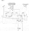
- FIG. 3 is an overall circuit diagram of a hydraulic circuit according to the first embodiment of the present invention.
- the hydraulic circuit comprises a main channel for conducting the oil to apply pressure to a piston portion in each hydraulic mechanism, and a pilot channel branched from the main channel.
- the pilot channel is provided with a solenoid valve, and operation of a logic valve or the like provided in the main channel is controlled by controlling the conduction path of the oil conducted in the pilot channel. That is, the oil conduction path in the main channel is thus determined.
- the description below is made, in consideration of visibility, with reference to diagrams ( FIG. 4 to FIG. 8 ) of the main circuit as a part of the hydraulic circuit.
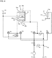
- FIG. 4 is a schematic view of the main part of the hydraulic circuit.
- the tank T1 is built in the molding machine 1, and the oil conducted in the hydraulic circuit in each step is stored therein.
- a tank T2 is externally connected to the molding machine 1 and stores additional oil used in a mold closing step described later.
- the tank T1 and the tank T2 are separate components in FIG. 4 but may be connected with each other by a channel (not shown).
- a flow adjustment valve V1 has, for example, a constriction shape, so that a cross-sectional area of a path can be reduced to adjust a flow rate of the oil conducted in the hydraulic circuit.
- a pressure adjustment valve V2 is configured to allow a part of the oil conducted in the hydraulic circuit to escape to another path, thereby adjusting the hydraulic pressure.
- Path control valves V3-V6 are logic valves V3-V6 for controlling oil conduction by opening and closing to determine a conduction path.
- a path control valve V7 is a solenoid valve V7 configured to control the conduction of oil at the position thereof.
- a path control valve V8 is a prefill valve V8 configured to suck a large amount of oil from the tank T2 toward the hydraulic mechanism 45 as appropriate and to prevent a backflow from the hydraulic mechanism 45 to the tank T2.
- a path control valve V9 is a relief valve V9 configured to be opened to release pressure when pressure exceeding a set value is applied.
- the logic valves V3-V6, the prefill valve V8, and the relief valve V9 are connected to the pilot channel (see FIG. 3 , not shown in FIG. 4 ⁇ FIG. 8 ), and the operation thereof is respectively controlled by a corresponding solenoid valve.
- FIG. 5 shows the oil conduction path in the hydraulic circuit when the molten resin 11a is injected in FIG. 4 .
- an oil flow avoided from the main channel for pressure reduction by the pressure adjustment valve V2 is omitted from the drawing.
- a solenoid valve (not shown) is controlled so that the logic valves V3, V5 and the prefill valve V8 are closed, and the logic valve V4 is opened.
- the pump P sends the oil stored in the tank T1 to the downstream side.
- a flow rate of the supplied oil is adjusted by passing through the flow adjustment valve V1.
- the oil is then injected in the cylinder 17a of the hydraulic mechanism 17 through the logic valve V4 in an opened state and pushes down the piston 17b.
- the molten resin 11a is injected through such a step, and, as shown in FIG. 1 , the parison 23 is formed by extruding downward the molten resin 11a from a die slit provided in the injection part 18.
- the piston 17b is pushed up by the pressure of the molten resin 11a, and the oil in the cylinder 17a is pushed out.
- This oil passes through the pilot channel (not shown), is conducted to a return position B shown in FIG. 4 , and is then returned to the tank T1.
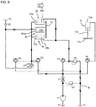
- FIG. 6 shows the oil conduction path in the hydraulic circuit when the molds 21, 22 are closed in FIG. 4 .
- the logic valve V5 is shifted to an opened state
- the logic valve V4 is shifted to a closed state from the state of FIG. 5 .
- a solenoid valve (not shown) is controlled to close the logic valves V3, V4, V6 and open the logic valve V5.
- the solenoid valve V7 is closed.
- the closed state of the solenoid valve V7 is a state where conduction from an upstream side to a downstream side of the solenoid valve V7 is restricted as shown in FIG. 7 .
- the pump P sends the oil stored in the Tank T1 to the downstream side.
- a flow rate of the supplied oil is adjusted by passing through the flow adjustment valve V1.
- the oil is then injected into a cylinder 35a of the hydraulic mechanism 35 through the logic valve V5 in an opened state and moves a piston 35b in a mold closing direction (a direction of an arrow X) of the molds 21, 22. In this way, the molds 21, 22 are closed.
- the oil located on a right side of the hydraulic mechanism 35 in FIG. 6 is pushed out and returned to the tank T1 through the relief valve V9.
- a cylinder 45a of the hydraulic mechanism 45 is connected to the tank T2 via the prefill valve V8.
- a piston 45b is also moved in the direction of the arrow X.
- oil from the tank T2 is sucked into the cylinder 45a.
- the cylinder 45a of the hydraulic mechanism 45 has a large capacity. Therefore, if the hydraulic mechanism 45 is configured so that oil from the pump P is injected into the cylinder 45a, it is necessary to use the pump capable of outputting a large capacity, and thus the pump P becomes large.
- the oil from the tank T2 is passively injected into the cylinder 45a with the movement of the piston 35b, and thus an increase in the size of the pump P can be avoided.
- a step is performed to further apply and maintain pressure to the molds 21, 22 in the closing direction.
- This step is referred to as a pressure maintenance.
- the pressure maintenance step may be started in the middle of the mold closing step or may be performed after the mold closing step is completed.
- FIG. 7 shows the oil conduction path in the hydraulic circuit when pressure applied to the molds 21, 22 is maintained in FIG. 4 .
- FIG. 7 shows the oil conduction path when the pressure maintenance step is additionally performed in the middle of the mold closing step, but in actuality, when the molds 21, 22 are brought into contact with each other and the mold closing step is completed, the pressure is applied to the molds 21, 22 while oil flow itself stops.
- the oil hardly flows in such a state, and the hydraulic pressure is applied to the piston 45b.
- the solenoid valve V7 is shifted to the opened state from the state of FIG. 6 . More specifically, a solenoid valve (not shown) is controlled to close the logic valves V3, V4, V6 and open the logic valve V5.
- the solenoid valve V7 is shifted to the opened state. Under such a condition, the pump P sends the oil stored in the Tank T1 to the downstream side. A flow rate of the supplied oil is adjusted by passing through the flow adjustment valve V1. The oil then passes through the logic valve V5 and the solenoid valve V7 in the opened state and applies pressure to the cylinder 45a of the hydraulic mechanism 45 in the direction of the arrow X to maintain the pressure applied to the molds 21, 22.
- FIG. 8 shows the oil conduction path in the hydraulic circuit when the molds 21, 22 are opened in FIG. 4 .
- the molds 21, 22 are opened, at least the logic valve V5 and the solenoid valve V7 are shifted to the closed state from the state of FIG. 9 , and the logic valves V3, V6 are shifted to the opened state.
- a solenoid valve (not shown) is controlled to close the logic valve V5 and open the logic valves V3, V6.
- the solenoid valve V7 is closed. Under such a condition, the pump P sends the oil stored in the Tank T1 to the downstream side. A flow rate of the supplied oil is adjusted by passing through the flow adjustment valve V1.
- the oil then passes through the logic valve V3 in the opened state and applies pressure to the piston 35b of the hydraulic mechanism 35 in a direction of an arrow Y in FIG. 8 .
- the molds 21, 22 are opened.
- the oil located on a left side of the piston 35 b in the cylinder 35a is pushed out and returned to the tank T1 through the logic valve V6.
- the oil in the cylinder 45a is pushed out and returned to the tank T1 through the solenoid valve V7 and the logic valve V6.
- FIG. 9 is a block diagram showing features of a multi-functional valve unit U according to the first embodiment of the present invention.
- the multi-functional valve unit U comprises the flow adjustment valve V1, the pressure adjustment valve V2, and the path control valves V3-V9, which are described above, as well as pipes for connecting these valves.
- the pump P, the multi-functional valve unit U, and the hydraulic mechanisms 17, 35, 45 are arranged from the upstream side to the downstream side.
- the configuration according to the first embodiment satisfies La>Lb, where La is an average value of path lengths between the multi-functional valve unit U and each of the hydraulic mechanisms (the hydraulic mechanism 17, 35, 45), Lb is a path length between the multi-functional valve unit U and the pump P. Since pressure between the multi-functional valve unit U and the pump P is high, damage to the pipes can be suppressed by shortening a distance therebetween.
- the value of La/Lb may be, for example, 2 to 100, specifically, for example, 2, 3, 5, 10, 20, 30, 40, 50, 60, 70, 80, 90, 100, and may be within a range between any two of the exemplified values.
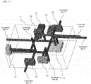
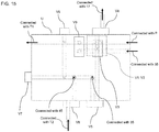
- FIGs. 10A and 10B are perspective views of the multi-functional valve unit U (excluding valves thereof) according to the first embodiment of the present invention. Particularly, in FIG. 10B , the inside is shown in a transparent manner.
- FIG. 11 and FIG. 12 are perspective views showing the multi-functional valve unit U according to the first embodiment of the present invention and a part of channels connected thereto.
- FIG. 13 to FIG. 15 each are a front view, a left side view, and a plan view of the multi-functional valve unit U according to the first embodiment of the present invention.
- the multi-functional valve unit U has a substantially rectangular parallelepiped shape.
- a plurality of channels in the multi-functional valve unit U is holes (for example, channel holes h1-h3 shown in FIG. 10A ) formed from a surface of the multi-functional valve unit U to the inside. That is, each of the channels is provided so as to extend from any of the surfaces the substantially rectangular parallelepiped of the multi-functional valve unit U toward a vertical direction of the surface. Desired channels can be easily formed with such a configuration.
- the flow adjustment valve V1, the pressure adjustment valve V2, and each of the path control valves V3-V9 are provided at valve installation positions V1a-V9a on the surfaces of the substantially rectangular parallelepiped.
- the logic valves V3, V5, the prefill valve V8, and the relief valve V9 are respectively provided at the valve installation positions V3a, V5a, V8a, V9a on the surfaces shown in FIG. 10A .
- the channel holes h1, h2 included in the valve installation position V5a can be connected to each other so as to conduct and interrupt the oil via the logic valve V5. The same applies to the valve installation positions V3a, V9a.
- the channel hole h3 included in the valve installation position V8a can be connected to an external channel outside the multi-functional valve unit U so as to conduct and interrupt the oil via the prefill valve V8.
- the flow adjustment valve V1 and the pressure adjustment valve V2 are illustrated as an integrated valve.
- the first embodiment shown in FIG. 10A, FIG. 10B , and FIG. 11 to FIG. 15 is merely an example, and different channel configuration may be adopted for details.
- the pilot channel connected to the logic valves V3-V6, the prefill valve V8, and the relief valve V9 and the solenoid valves for controlling these valves are also arranged in the multi-functional valve unit U.
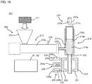
- a molding machine 201 of the second embodiment of the present invention comprises a resin supply device 202, an injection part 218, first and second platens 231, 232 on which first and second molds 221, 222 are mounted, a hydraulic mechanism for injection 217, a hydraulic mechanism for opening and closing 235, and a hydraulic mechanism for pressure maintenance 245.
- the resin supply device 202 comprises a hopper 212, an extruder 213, and an injector 216.
- the extruder 213 and the injection part 218 are connected via a connecting pipe 225.
- the hydraulic mechanisms 217, 235, 245 are driven by hydraulic pressure generated in a hydraulic circuit C shown in FIG. 17 .
- Two hydraulic mechanisms 235 are provided on a diagonal line of the mold 222, and the hydraulic mechanism 245 is disposed between the two the hydraulic mechanisms 235.
- the molding machine 201 is preferably a foam molding machine for foam molding.
- the hopper 212 is used for charging raw resin 211 in a cylinder 213a of the extruder 213.
- the raw resin is, for example, a thermoplastic resin such as polyolefin.
- the polyolefin include low-density polyethylene, linear low-density polyethylene, high-density polyethylene, polypropylene, ethylene-propylene copolymer, and a mixture thereof.
- the raw resin 211 is charged in the cylinder 213a from the hopper 212 and then melted into molten resin by being heated in the cylinder 213a.
- the raw resin 211 is conveyed toward a front end of the cylinder 213a by rotation of a screw disposed in the cylinder 213a.
- the screw is disposed in the cylinder 213a and kneads and conveys the molten resin by rotation.
- a gear device is provided at a base end of the screw, and the screw is driven by the gear device to rotate.
- the number of the screws disposed in the cylinder 213a may be one or more.
- the cylinder 213a is provided with the injector 216 for injecting a foaming agent into the cylinder 213a.
- the injector 216 can be omitted.
- the foaming agent injected from the injector 216 include physical foaming agents, chemical foaming agents, and a mixture thereof, and physical foaming agents are preferred.
- physical foaming agents inorganic physical foaming agents, such as air, carbon dioxide gas, nitrogen gas, and water, organic physical foaming agents, such as butane, pentane, hexane, dichloromethane, and dichloroethane, and supercritical fluids of these agents can be used.
- the supercritical fluid it is preferable to use carbon dioxide, nitrogen, or the like.
- the supercritical fluid can be obtained under conditions of critical temperature at -149.1°C, and critical pressure at 3.4MPa or higher, and in case of carbon dioxide, under conditions of critical temperature at 31°C, and critical pressure at 7.4MPa or higher.
- the chemical foaming agents include those that generate carbon dioxide as a result of a chemical reaction with an acid (e.g., citric acid or a salt thereof) or a base (e.g., sodium bicarbonate).
- the chemical foaming agents may be charged from the hopper 212, instead of being injected from the injector 216.
- the molten resin 211a to which the foaming agent is added (foam molten resin) or the molten resin 211a to which no foaming agent is added (solid molten resin) is extruded from a resin extrusion port of the cylinder 213a and injected into the injection part 218 via the connecting pipe 225.
- the injection part 218 comprises a cylinder 218a, a piston 218b slidable therein, and a mandrel 218c, the cylinder 218a is configured to store the molten resin 211a inside.
- the molten resin 211a is injected downward from a die slit provided at a tip of the injection part 218 to form a parison 223.
- the parison 223 has a cylindrical shape in FIG. 16 , but is not limited to this example, and may have another shape (for example, a sheet shape).
- the injection part 218 in FIG. 16 is an injection part of an in-die accumulator type provided with an accumulator in a head but may be an injection part of a side accumulator type provided with an accumulator adjacent to the head.
- the piston 218b is connected to the hydraulic mechanism for injection 217.
- the injection part 218 is driven by a hydraulic mechanism 217 and injects the molten resin 211a between the molds 221, 222 to form the parison 223.
- the hydraulic mechanism 217 comprises a cylinder 217a and a piston 217b slidable therein.
- the piston 217b is connected to the piston 218b via the connecting plate 17c.
- the piston 217b can be driven by controlling hydraulic pressure in the cylinder 217a.
- the hydraulic circuit C for driving the piston 217b will be described later.
- a molded body can be formed by closing, in a state the parison 223 is disposed between the molds 221, 222, the molds 221, 222 and preferably maintaining pressure applied to the molds 221, 222.
- a molding method using the molds 221, 222 is not specifically limited, may be blow molding in which air is blown into a cavity of the molds 221, 222 for molding, may be vacuum molding in which the inside of the cavity of the molds 221, 222 is decompressed to form a parison, or may be a combination thereof.
- the parison becomes a foam parison.
- the molds 221, 222 are mounted on the platens 231, 232.
- the mold 222 is connected to the hydraulic mechanism for opening and closing 235 and the hydraulic mechanism for pressure maintenance 245 via the platen 32.
- the platens 231, 232 are configured to be driven by the hydraulic mechanism for opening and closing 235 to open and close the molds 221, 222.
- the hydraulic mechanism for pressure maintenance is configured to maintain pressure applied to the molds 221, 222 in a closed state.
- the hydraulic mechanisms 235, 245 comprises cylinders 235a, 245a, respectively, and pistons 235b, 245b slidable therein, respectively.
- the pistons 235b, 245b can be driven by controlling hydraulic pressure in the cylinders 235a, 245a.
- the hydraulic circuit C is a circuit that conducts the oil generating hydraulic pressure.
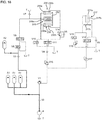
- FIG. 17 is an overall circuit diagram of the hydraulic circuit C according to the second embodiment of the present invention.
- FIG. 18 to FIG. 23 are circuit diagrams showing the main part of the hydraulic circuit C.
- the hydraulic circuit C comprises a tank T, a pump P, valves V1-V17, a first accumulator A1, and a second accumulator A2. Each component is connected via a pipe.
- the tank T oil to be sent to the hydraulic circuit C is stored.
- the pump P is connected to the tank T through the pipe and sucks the oil from the tank T to send the oil to the downstream side.
- the valve V1 is a logic valve and is opened and closed to control oil conduction.
- the logic valve can be controlled by a solenoid valve (not shown) to be opened and closed.
- the valves V2-V7 are check valves that allow fluid to flow only from the upstream (" ⁇ " side) to the downstream ("o" side) and prevent the flow from the downstream to the upstream.
- the valves V8-V13 are direction control valves and electromagnetically control oil flow.
- the valves V14-V15 are relief valves and release pressure when pressure exceeding a set value is applied.
- the valves V16-V17 are pressure reducing valves that reduce pressure on the upstream side for transmission to the downstream side.
- the accumulators A1, A2 have a function of accumulating oil and releasing the accumulated oil as appropriate. Gas is sealed in the accumulators.
- the oil is accumulated in the accumulators when hydraulic pressure in the pipe to which the accumulators are connected is higher than pressure in the accumulators, and the oil is discharged when the hydraulic pressure is lower than the pressure in the accumulators.
- the accumulators A1, A2 are disposed below the extruder 213 and on a back side of the hydraulic mechanism 235.
- the accumulators A1, A2 are usually large in size, such an arrangement allows the accumulators A1, A2 to be installed without increasing installation space of the molding machine 201.
- the accumulator A1 is divided into a plurality of parts. Each part of the accumulator A1 is connected to a pipe in parallel. Consequently, the operation of the molding machine 201 can be continued even if one of the parts of the accumulator A1 fails to operate properly.
- an oil accumulation step a step of injecting the molten resin 211a, a step of closing the molds 221, 222, a step of maintaining pressure applied to the molds 221, 222, a step of opening the molds 221, 222, and a step of injecting molten resin to the injection part 218 are performed.
- the oil conduction path in each step is described below.
- FIG. 18 shows the oil conduction path when oil is accumulated in accumulators A1, A2.
- the valves V1, V8 are closed.
- the oil delivered from the pump P is accumulated in the accumulator A1 through the valve V2 and further accumulated in the accumulator A2 through the valve V3.
- FIG. 19 shows the oil conduction path when the molten resin 211a is injected.
- the valves V8, V11, V13 are closed, and the valves V1, V12 are opened.
- the molten resin 211a can be injected at high speed by driving the hydraulic mechanism 217 by hydraulic pressure generated by the oil discharged from the accumulator A1, even when the capacity of the pump P is small.
- the molten resin 211a is foam molten resin, the growth of bubbles and bubble breakage are suppressed.
- the oil discharged from the accumulator A1 is not supplied to the cylinders 235a, 245a, and is supplied only to the cylinder 217a.
- this oil is supplied to the cylinders 235a, 245a, the injection may become unstable, while the injection is stabilized at high speed by supplying this oil only to the cylinder 217a.
- the description of the pump P is omitted as appropriate.
- the pump P is operated as appropriate to supply oil into the pipe to generate hydraulic pressure.
- the pump P can be controlled to operate when the amount of oil accumulated in the accumulators decreases. In this case, since the pump P is not always operated, energy consumption can be reduced.
- FIG. 20 shows the oil conduction path when the molds 221, 222 are closed.
- the valves V8, V10, V12 are closed, and the valves V1, V11, V14 are opened.
- the cylinder 245a of the hydraulic mechanism 245 is connected to the tank T via the valve V7.
- the piston 245b also moves in the direction of the arrow X.
- oil from the tank T is sucked into the cylinder 245a.
- the cylinder 245a of the hydraulic mechanism 245 has a large capacity. Therefore, if the cylinder 245a is configured so that the oil from the accumulator A1 is injected into the cylinder 245a, the accumulator A1 is enlarged accordingly.
- the oil from the tank T is passively injected in the cylinder 245a with the movement of the piston 235b, and thus the enlargement of the accumulator A1 is suppressed.
- the molds 221, 222 can be closed at high speed by driving the hydraulic mechanism 235 by the hydraulic pressure generated by the oil discharged from the accumulator A1.
- the molten resin 211a is foam molten resin, the growth of bubbles and bubble breakage are suppressed.
- the oil discharged from the accumulator A1 is not supplied to the cylinders 217a, 245a, and is supplied only to the cylinder 235a.
- this oil is supplied to the cylinders 217a, 245a, the mold closing may become unstable, while the mold closing is stabilized at high speed by supplying this oil only to the cylinder 235a.
- the oil from the accumulator A1 is supplied only to the cylinder 217a in the step of injecting the molten resin 211a and is supplied only to the cylinder 235a in the step of closing the molds 221, 222. Consequently, the hydraulic mechanisms 217, 235 are sequentially driven. The operation is stabilized by supplying the oil to the cylinders 217a, 235a sequentially rather than simultaneously.
- FIG. 21 shows the oil conduction path when pressure applied to the molds 21, 22 is maintained (mold clamping).
- the valves V10, V12 are closed, and the valves V1, V8, V9, V11, V14 are opened.
- valves V8, V9 When the valves V8, V9 are opened from the state of FIG. 20 , the oil in the accumulator A2 is discharged into the pipe, passes through the valves V8, V9, and is injected to a back side of the piston 245b in the cylinder 245a. Consequently, pressure is applied to the piston 245b, and the pressure is maintained with the molds 221, 222 closed.
- the oil discharged from the accumulator A2 is not supplied to the cylinders 217a, 235a and is supplied only to the cylinder 245a.
- the hydraulic pressure generated by the oil discharged from the accumulator decreases with a decrease in the internal pressure of the accumulator accompanying the oil discharge.
- a high hydraulic pressure can be applied to the piston 245b.
- the hydraulic pressure is applied to the piston 245b, while the oil hardly flows.
- the oil from the accumulator A2 can be injected into the cylinder 245a by opening the valves V8, V9 before the molds 221, 222 come into contact. In this case, the oil flows through the conduction path shown in FIG. 21 until the molds 221, 222 are closed, and the oil flow is stopped when the molds 221, 222 are closed.
- FIG. 22 shows the oil conduction path when the molds 221, 222 are opened.
- the valve V12 are closed, and the valves V1, V9, V11, V14 are opened.
- the paths of the valves V9, V11 are switched from those in the step of maintaining pressure applied to the molds 221, 222. That is, pipes at both ends of the valves V9, V11 are connected in parallel in the step of maintaining pressure applied to the molds 221, 222, while the pipes at both ends are crossed and connected in the step of opening the molds 221, 222.
- valve V10 When the valve V10 is opened from the state of FIG. 21 and the paths of the valves V9, V11 are switched, the oil in the accumulator A1 passes through the valve V1, is decompressed by the valve V16, passes through the valves V11, V6, and is injected into the front side of the piston 235b in the cylinder 235a. Consequently, the piston 235b is pushed in (moves in the mold opening direction (the direction of the arrow Y) of the molds 221 and 222). When the piston 235b is pushed in, the oil on the back side of the piston 235b in the cylinder 235a is pushed out and returned to the tank T through the valve V10 and the valve V11.
- FIG. 23 shows the oil conduction path when the molten resin is injected into the injection part 218.
- the valve V12 is closed, and the valves V13, V15 are opened.
- the piston 218b is pushed up by the pressure of the molten resin 211a.
- the piston 217b is pushed into the cylinder 217a.
- the oil on a back side of the piston 217b in the cylinder 217a is pushed out and moves to a front side of the piston 217b in the cylinder 217a through the valves V13, V15, V5.
- the pressure in the pipe from the back side to the front side of the piston 217b in the cylinder 217a is regulated by the valve (back-pressure adjustment valve) 15, and thereby the pressure (back pressure) on the back side of the piston 217b is adjusted.
- the bubble breakage is suppressed by adjusting the back pressure of the piston 217b by the valve V15 to continuously apply an appropriate pressure to the molten resin 211a in the injection part 218.
- the oil is accumulated in the accumulators A1 and A2 as in the oil accumulation step described above. That is, the oil accumulation step and the step of injecting molten resin to the injection part 218 can be performed simultaneously.
- the molding machine 201 can perform injection and mold closing at high speed. When used in manufacturing a foam molded body, the molding machine 201 can suppress bubble breakage and increase the expansion ratio of the foam molded body.
- the manufacturing method of foam molded body according to the second embodiment comprises an injection step, a mold closing step, and a pressure maintenance step.
- the pressure maintenance step can be omitted.
- a foam parison is formed by being driven by the hydraulic mechanism 217 and injecting a foam molten resin between the molds 221, 222.
- the mold closing step the molds 221, 222 are closed by being driven by the hydraulic mechanism 235.
- a foam molded body can be formed by molding the foam parison with the molds 221, 222.
- the hydraulic mechanisms 217, 235 are sequentially driven by the hydraulic pressure generated by the oil discharged from the accumulator A1. Such a configuration makes it possible to perform the injection and the mold closing stably and at high speed.
- the pressure applied to the molds 221, 222 in a closed state is maintained by the hydraulic mechanism 245. Consequently, welding of the foam molded body at a parting line is strengthened.
- the hydraulic mechanism 245 is driven by the hydraulic pressure generated by the oil discharged from the accumulator A2. Such a configuration makes it possible to maintain the pressure with a strong hydraulic pressure.
- the molding machine 1 configured to achieve the space saving and simplification of the hydraulic circuit.
- the molding machine 201 capable of increasing the foaming ratio of the foam molded body.
Landscapes
- Engineering & Computer Science (AREA)
- Mechanical Engineering (AREA)
- Manufacturing & Machinery (AREA)
- Moulds For Moulding Plastics Or The Like (AREA)
- Injection Moulding Of Plastics Or The Like (AREA)
- Threshing Machine Elements (AREA)
- Catching Or Destruction (AREA)
- Formation And Processing Of Food Products (AREA)
Abstract
Description
- The present invention relates to a molding machine.
- Conventionally, there is known a molding machine configured to form a molded body by injecting resin into a cavity of split molds which can be opened and closed and then closing the split molds to apply and maintain pressure to the split molds in a closed state. In such a molding machine, hydraulic pressure is used as power in a resin injection step, a step of opening and closing the split molds, and a pressure maintenance step. That is, a hydraulic circuit to conduct oil for generating the hydraulic pressure is provided in the molding machine.
- In foam molding, a foam parison formed by injecting foam molten resin from an injection part is disposed between a pair of split molds, and the split molds are then closed to form a foam molded body (see Patent Literature 1).
- [Patent Literature 1]
WO2013/111692 - The hydraulic circuit includes a tank for storing oil and a pump for pumping the oil and further includes a flow adjustment valve, a pressure adjustment valve, and a plurality of path control valves. Here, the path control valve is a valve that determines a conduction path of the oil and may be, for example, various types of logic valves or a solenoid valve for operating the logic valves. Generally, an arrangement position in the hydraulic circuit is different for each type of valve. For example, the flow adjustment valve and the pressure adjustment valve are disposed on an upstream side (at positions close to the tank and the pump), and path control valves, such as the solenoid valve and the logic valve, are disposed on a downstream side (at positions close to a hydraulic mechanism to be controlled). Consequently, there arises a problem that the hydraulic circuit takes up space and becomes complicated. In other words, the molding machines according to prior arts tend to be large in overall size.
- The first viewpoint of the present invention has been made in view of such circumstances and provides a molding machine configured to achieve space saving and simplification of the hydraulic circuit.
- Bubbles of the foam molten resin start growing immediately after being injected from the injection part. Therefore, if a duration time from the injection of the foam molten resin by the injection part to the closing of the split molds is long, the bubbles grow excessively and break, resulting in a decrease in an expansion ratio of the foam molded body.
- The second viewpoint of the present invention has been made in view of such circumstances and provides a molding machine capable of raising the expansion ratio of the foam molded body.
- According to the first viewpoint of the present invention, provided is a molding machine configured to form a molded body by closing, in a state where a parison is disposed by injecting molten resin between first and second molds capable of being opened and closed, the first and second molds and maintaining pressure applied to the first and second molds, comprising: a hydraulic circuit to conduct oil for generating hydraulic pressure; a flow adjustment valve, a pressure adjustment valve, and a path control valve included in the hydraulic circuit; and a multi-functional valve unit, wherein at least hydraulic mechanisms injecting the molten resin, opening and closing the molds, and maintaining the pressure applied to the first and second molds are driven by the hydraulic pressure; the flow adjustment valve adjusts a flow rate of the oil; the pressure adjustment valve adjusts the hydraulic pressure; the path control valve determines a conduction path of the oil in the hydraulic circuit; and the multi-functional valve unit integrally comprises the flow adjustment valve, the pressure adjustment valve, and the path control valve.
- The molding machine according to the first viewpoint of the present invention comprises the multi-functional valve unit in the hydraulic circuit and is characterized in that the flow adjustment valve, the pressure adjustment valve, and the path control valve are integrally accommodated in the multi-functional valve unit. The flow adjustment valve and the pressure adjustment valve, and the path control valve, which have been conventionally provided separately, are accommodated integrally, and thus the space saving and simplification of the hydraulic circuit in the molding machine can be achieved.
- Consequently, the overall size of the molding machine can be reduced.
- Hereinafter, various embodiments of the present invention will be exemplified. The embodiments shown hereinafter can be combined with each other.
- Preferably, the molding machine further comprises a pump, wherein the pump is configured to suck out the oil from a tank for storing the oil and conduct the oil to a downstream side; the pump, the multi-functional valve unit, and the hydraulic mechanisms are arranged from an upstream side to a downstream side in the hydraulic circuit; and La>Lb, where La is an average value of path lengths between the multi-functional valve unit and the hydraulic mechanisms in the hydraulic circuit, and Lb is a path length between the pump and the multi-functional valve unit in the hydraulic circuit.
- Preferably, the multi-functional valve unit has a substantially rectangular parallelepiped shape; the flow adjustment valve, the pressure adjustment valve, and the path control valve are provided on a surface of the substantially rectangular parallelepiped.
- Preferably, a plurality of channels in the multi-functional valve unit is provided so as to extend from a surface of the substantially rectangular parallelepiped along a direction perpendicular to the surface.
- Preferably, the molding machine is configured to have two stages and comprises a resin supply device for injecting the resin, wherein the resin supply device comprises an extruder for melting and kneading raw resin into molten resin; the first and second molds and the multi-functional valve unit are provided in a lower stage; the resin supply device is provided in an upper stage; the first and second molds and the multi-functional valve unit are disposed along a longitudinal direction of the extruder; and the first and second molds are opened and closed along the longitudinal direction of the extruder.
- According to the second viewpoint of the present invention, provided is a molding machine comprising: a hydraulic circuit; a hydraulic mechanism for injection; a hydraulic mechanism for opening and closing; an injection part; and first and second platens on which first and second molds are mounted, wherein the hydraulic circuit conducts oil for generating hydraulic pressure; the hydraulic mechanism for injection and the hydraulic mechanism for opening and closing are driven by hydraulic pressure; the injection part is driven by the hydraulic mechanism for injection to inject molten resin between the first and second molds to form a parison; the first and second platens are configured to be driven by the hydraulic mechanism for opening and closing and open and close the first and second molds; the hydraulic circuit comprises a first accumulator for accumulating oil; and the hydraulic mechanism for injection and the hydraulic mechanism for opening and closing are sequentially driven by hydraulic pressure generated by the oil discharged from the first accumulator.
- In the molding machine of the present invention, the hydraulic mechanism for injection and the hydraulic mechanism for opening and closing are sequentially driven by the hydraulic pressure generated by the oil discharged from the first accumulator. This makes it possible to perform injection and mold closing at high speed, and thus bubble breakage can be prevented, and the expansion ratio of the foam molded body can be increased.
- Hereinafter, various embodiments of the present invention will be exemplified. The embodiments shown hereinafter can be combined with each other.
- Preferably, the first accumulator is divided into a plurality of parts.
- Preferably, the molding machine comprises a hydraulic mechanism for pressure maintenance, wherein the hydraulic mechanism for pressure maintenance is driven by hydraulic pressure; the hydraulic mechanism for pressure maintenance is configured to maintain pressure applied to the first and second molds in a closed state; the hydraulic circuit comprises a second accumulator for storing oil; and the hydraulic mechanism for pressure maintenance is driven by hydraulic pressure generated by the oil discharged from the second accumulator.
- Preferably, the hydraulic pressure generated by the oil discharged from the second accumulator does not drive the hydraulic mechanism for opening and closing and the hydraulic mechanism for injection.
- Preferably, the molding machine comprises a back-pressure adjustment valve for adjusting back pressure in the hydraulic mechanism for injection when molten resin is injected into the injection part.
- Preferably, the molding machine comprises an extruder for melting raw resin into molten resin, wherein the first accumulator is disposed below the extruder and on a back side of the hydraulic mechanism for opening and closing.
- Further, according to another viewpoint derived from the second viewpoint of the present invention, provided is a method for manufacturing a foam molded body by means of the afore-mentioned molding machine, comprising: an injection step of injecting, by being driven by the hydraulic mechanism for injection, a foam molten resin between the first and second molds to form a foam parison; and a mold closing step of closing the first and second molds by being driven by the hydraulic mechanism for opening and closing, wherein the hydraulic mechanism for injection and the hydraulic mechanism for opening and closing are sequentially driven by hydraulic pressure generated by the oil discharged from the first accumulator.
- Preferably, the method comprises a pressure maintenance step of maintaining pressure applied to the first and second molds in a closed state by a hydraulic mechanism for pressure maintenance, wherein the hydraulic mechanism for pressure maintenance is driven by hydraulic pressure generated by oil discharged from a second accumulator.
-
-
FIG. 1 is a side schematic view of amolding machine 1 according to a first embodiment of the present invention. -
FIG. 2A and FIG. 2B are a conceptual diagram showing a configuration of alower stage 3 of themolding machine 1 according to the first embodiment of the present invention. Specifically,FIG. 2A showsmolds FIG. 2B shows themolds -
FIG. 3 is an overall circuit diagram of a hydraulic circuit according to the first embodiment of the present invention. -
FIG. 4 is a schematic view of the main part of the hydraulic circuit. -
FIG. 5 shows an oil conduction path in the hydraulic circuit whenmolten resin 11a is injected inFIG. 4 . -
FIG. 6 shows the oil conduction path in the hydraulic circuit when themolds FIG. 4 . -
FIG. 7 shows the oil conduction path in the hydraulic circuit when pressure applied to themolds FIG. 4 . -
FIG. 8 shows the oil conduction path in the hydraulic circuit when themolds FIG. 4 . -
FIG. 9 is a block diagram showing features of a multi-functional valve unit U according to the first embodiment of the present invention. -
FIG. 10A and FIG. 10B are perspective views of the multi-functional valve unit U (excluding valves thereof) according to the first embodiment of the present invention. Particularly, inFIG. 10B , the inside is shown in a transparent manner. -
FIG. 11 is a perspective view showing the multi-functional valve unit U according to the first embodiment of the present invention and a part of channels connected thereto. -
FIG. 12 is another perspective view showing the multi-functional valve unit U according to the first embodiment of the present invention and a part of channels connected thereto. -
FIG. 13 is a front view of the multi-functional valve unit U according to the first embodiment of the present invention. -
FIG. 14 is a left side view of the multi-functional valve unit U according to the first embodiment of the present invention. -
FIG. 15 is a plan view of the multi-functional valve unit U according to the first embodiment of the present invention. -
FIG. 16 shows an example of themolding machine 1 that can be used in a method for manufacturing a foam molded body according to a second embodiment of the present invention. -
FIG. 17 is an overall circuit diagram of a hydraulic circuit C according to the second embodiment of the present invention. -
FIG. 18 is a schematic view of the main part of the hydraulic circuit C and shows the oil conduction path when oil is accumulated in accumulators A1, A2. -
FIG. 19 is a schematic view of the main part of the hydraulic circuit C and shows the oil conduction path when themolten resin 211a is injected. -
FIG. 20 is a schematic view of the main part of the hydraulic circuit C and shows the oil conduction path when themolds -
FIG. 21 is a schematic view of the main part of the hydraulic circuit C and shows the oil conduction path when pressure applied to themolds -
FIG. 22 is a schematic view of the main part of the hydraulic circuit C and shows the oil conduction path when themolds -
FIG. 23 is a schematic view of the main part of the hydraulic circuit C and shows the oil conduction path when the molten resin is injected to theinjection part 218. - Hereinafter, embodiments of the present invention will be described. Various characteristics shown in the embodiments described below can be combined with each other. Further, the invention is independently established for each characteristic. The first and second embodiments are particularly related to the inventions of the first and second viewpoints, respectively.
- First, the first embodiment of the present invention will be described.
- First, a molding machine according to the first embodiment of the present invention will be described.
FIG. 1 is a side schematic view of amolding machine 1 according to the first embodiment of the present invention. As shown here, themolding machine 1 has a substantially rectangular parallelepiped shape as a whole, and a depth d is longer than a width w. Further, themolding machine 1 is configured to have two stages including anupper stage 2 and alower stage 3. The configuration of theupper stage 2 and the lower stage is described in detail below. - The configuration of the
upper stage 2 is described. Theupper stage 2 includes aresin supply device 5 and aninjection part 18. Theresin supply device 5 comprises ahopper 12 and anextruder 13. Theextruder 13 is connected to theinjection part 18 via a connectingpipe 25. - The
hopper 12 is used for chargingraw resin 11 in acylinder 13a of theextruder 13. Although the form of theraw resin 11 is not specifically limited, pellet-shaped resin is usually used. Theraw resin 11 is, for example, a thermoplastic resin such as polyolefin. Examples of the polyolefin include low-density polyethylene, linear low-density polyethylene, high-density polyethylene, polypropylene, ethylene-propylene copolymer, and a mixture thereof. Theraw resin 11 is charged in thecylinder 13a from thehopper 12 and then melted and kneaded into molten resin by being heated in thecylinder 13a. Further, theraw resin 11 is conveyed toward a front end of thecylinder 13a by rotation of a screw disposed in thecylinder 13a. The screw is disposed in thecylinder 13a and kneads and conveys the molten resin by rotation. A gear device is provided at a base end of the screw, and the screw is driven by the gear device to rotate. The number of the screws disposed in thecylinder 13a may be one or more. - The
molten resin 11a is extruded from a resin extrusion port of thecylinder 13a and injected into theinjection part 18 via the connectingpipe 25. Theinjection part 18 comprises acylinder 18a, apiston 18b slidable therein, and amandrel 18c, and thecylinder 18a is configured to store themolten resin 11a inside. By moving thepiston 18b after a predetermined amount of themolten resin 11a is stored in thecylinder 18a, themolten resin 11a is injected downward from a die slit provided at a tip of theinjection part 18 to form aparison 23. Theparison 23 has a cylindrical shape inFIG. 1 , but is not limited to this example, and may have another shape (for example, a sheet shape). - One end of the
piston 18b is connected to a hydraulic mechanism forinjection 17. Thehydraulic mechanism 17 comprises acylinder 17a and apiston 17b slidable therein. Thepiston 17b is connected to thepiston 18b via a connectingplate 17c. Thepiston 17b can be driven by controlling hydraulic pressure in thecylinder 17a. A hydraulic circuit for driving thepiston 17b will be described later. - The configuration of the
lower stage 3 is described.FIG. 2A and FIG. 2B are conceptual diagrams showing the configuration of thelower stage 3 of themolding machine 1 according to the first embodiment of the present invention. Thelower stage 3 includes afirst mold 21, asecond mold 22, and a mold opening/closing andpressure maintenance device 30 to open and close the molds and maintain pressure, as well as a tank T1, a pump P, and a multi-functional valve unit U which are related to the hydraulic circuit described later. Themolds extruder 13. - Split molds comprising the
molds pressure maintenance device 30. As shown inFIG. 1 andFIG. 2 , a molded body can be formed by closing, in a state theparison 23 is disposed between themolds molds molds molds molds molds - As shown in
FIG. 2A and 2B , the mold opening/closing andpressure maintenance device 30 comprises first andsecond mold plates pressure receiving plate 33, atie bar 34, a hydraulic mechanism for mold opening and closing 35, and a hydraulic mechanism forpressure maintenance 45. In the first embodiment, thehydraulic mechanism 35 comprises a pair of hydraulic pressure cylinder mechanisms. Thehydraulic mechanism 45 comprises one hydraulic pressure cylinder mechanism. - The
first mold plate 31 comprises thefirst mold 21 on a rear surface. Thesecond mold plate 32 faces thefirst mold plate 31 on a front side. Thesecond mold plate 32 comprises thesecond mold 22. Thesecond mold 22 is held so as to face thefirst mold 21. Thepressure receiving plate 33 is provided on a side opposite to thefirst mold plate 31 when viewed from thesecond mold plate 32. Thetie bar 34 extends through thefirst mold plate 31, thesecond mold plate 32, and thepressure receiving plate 33. Thehydraulic mechanisms second mold plate 32 and thepressure receiving plate 33. - The
hydraulic mechanisms hydraulic mechanism 35 is used for opening and closing themolds hydraulic mechanism 45 is used for maintaining the pressure applied to themolds - For example, when the cylinder in the
hydraulic mechanism 35 is extended, thefirst mold plate 31 and thepressure receiving plate 33 fixed to thetie bar 34 are slid together with thetie bar 34 in a direction of an arrow A+ inFIG. 2A , and thesecond mold plate 32 through which thetie bar 34 passed is slid in a direction of an arrow A- inFIG. 2A . As a result, themolds mold plates FIG. 2A ) to a mold closing state (FIG. 2B ). Further, from the state ofFIG. 2B , thehydraulic mechanism 45 further applies pressure in a closing direction to maintain the pressure applied to themolds hydraulic mechanism 35 is contracted, thefirst mold plate 31 and thepressure receiving plate 33 fixed to thetie bar 34 are slid together in the direction of the arrow A- inFIG. 2B , and thesecond mold plate 32 through which thetie bar 34 passed is slid in the direction of the arrow A+ inFIG. 2B . As a result, themolds mold plates FIG. 2B ) to the mold opening state (FIG. 2A ). - The oil conducted in the hydraulic circuit is stored in the tank T1. The pump P is connected to the tank T1 via a
pipe 41 and sucks out the oil from the tank T1 and sends the oil to a downstream side where the multi-functional valve unit U is positioned. The multi-functional valve unit U comprises a plurality of pipes and a plurality of valves, and specifically, a flow adjustment valve, a pressure adjustment valve, and a path control valve are all accommodated therein as one unit. The flow adjustment valve has, for example, a constriction shape so that a cross-sectional area of a path can be reduced to adjust a flow rate of the oil conducted in the hydraulic circuit. The pressure adjustment valve is configured to allow a part of the oil conducted in the hydraulic circuit to escape to another path, thereby adjusting the hydraulic pressure. The path control valve is, for example, a solenoid valve and the like configured to switch circuits by electric operation, and a plurality of such path control valves are provided in the multi-functional valve unit U. By switching the hydraulic circuits, the hydraulic mechanism forinjection 17 used for the resin injection, the hydraulic mechanism for mold opening and closing 35 used to open and close themolds pressure maintenance 45 used for pressure maintenance are controlled. In this regard, while cylinder mechanisms are employed in all the mechanisms, this is merely an example, and another actuator (driving mechanism) may be employed. - Next, the oil conduction path in the hydraulic circuit is described for a purpose of each step. The hydraulic circuit is a circuit that conducts the oil generating hydraulic pressure.
-
FIG. 3 is an overall circuit diagram of a hydraulic circuit according to the first embodiment of the present invention. As shown inFIG. 3 , the hydraulic circuit comprises a main channel for conducting the oil to apply pressure to a piston portion in each hydraulic mechanism, and a pilot channel branched from the main channel. The pilot channel is provided with a solenoid valve, and operation of a logic valve or the like provided in the main channel is controlled by controlling the conduction path of the oil conducted in the pilot channel. That is, the oil conduction path in the main channel is thus determined. The description below is made, in consideration of visibility, with reference to diagrams (FIG. 4 to FIG. 8 ) of the main circuit as a part of the hydraulic circuit. -
FIG. 4 is a schematic view of the main part of the hydraulic circuit. The tank T1 is built in themolding machine 1, and the oil conducted in the hydraulic circuit in each step is stored therein. A tank T2 is externally connected to themolding machine 1 and stores additional oil used in a mold closing step described later. In this regard, the tank T1 and the tank T2 are separate components inFIG. 4 but may be connected with each other by a channel (not shown). - A flow adjustment valve V1 has, for example, a constriction shape, so that a cross-sectional area of a path can be reduced to adjust a flow rate of the oil conducted in the hydraulic circuit.
- A pressure adjustment valve V2 is configured to allow a part of the oil conducted in the hydraulic circuit to escape to another path, thereby adjusting the hydraulic pressure.
- Path control valves V3-V6 are logic valves V3-V6 for controlling oil conduction by opening and closing to determine a conduction path. A path control valve V7 is a solenoid valve V7 configured to control the conduction of oil at the position thereof. A path control valve V8 is a prefill valve V8 configured to suck a large amount of oil from the tank T2 toward the
hydraulic mechanism 45 as appropriate and to prevent a backflow from thehydraulic mechanism 45 to the tank T2. A path control valve V9 is a relief valve V9 configured to be opened to release pressure when pressure exceeding a set value is applied. Among the path control valves V3-V9, the logic valves V3-V6, the prefill valve V8, and the relief valve V9 are connected to the pilot channel (seeFIG. 3 , not shown inFIG. 4∼FIG. 8 ), and the operation thereof is respectively controlled by a corresponding solenoid valve. -
FIG. 5 shows the oil conduction path in the hydraulic circuit when themolten resin 11a is injected inFIG. 4 . Here, an oil flow avoided from the main channel for pressure reduction by the pressure adjustment valve V2 is omitted from the drawing. The same applies to the subsequent drawings. When themolten resin 11a is injected, a solenoid valve (not shown) is controlled so that the logic valves V3, V5 and the prefill valve V8 are closed, and the logic valve V4 is opened. Under such a condition, the pump P sends the oil stored in the tank T1 to the downstream side. A flow rate of the supplied oil is adjusted by passing through the flow adjustment valve V1. The oil is then injected in thecylinder 17a of thehydraulic mechanism 17 through the logic valve V4 in an opened state and pushes down thepiston 17b. Themolten resin 11a is injected through such a step, and, as shown inFIG. 1 , theparison 23 is formed by extruding downward themolten resin 11a from a die slit provided in theinjection part 18. Further, when theextruder 13 is operated to inject themolten resin 11a into theinjection part 18, thepiston 17b is pushed up by the pressure of themolten resin 11a, and the oil in thecylinder 17a is pushed out. This oil passes through the pilot channel (not shown), is conducted to a return position B shown inFIG. 4 , and is then returned to the tank T1. -
FIG. 6 shows the oil conduction path in the hydraulic circuit when themolds FIG. 4 . When themolds FIG. 5 . More specifically, a solenoid valve (not shown) is controlled to close the logic valves V3, V4, V6 and open the logic valve V5. In addition, the solenoid valve V7 is closed. In this regard, strictly speaking, the closed state of the solenoid valve V7 is a state where conduction from an upstream side to a downstream side of the solenoid valve V7 is restricted as shown inFIG. 7 . Under such a condition, the pump P sends the oil stored in the Tank T1 to the downstream side. A flow rate of the supplied oil is adjusted by passing through the flow adjustment valve V1. The oil is then injected into acylinder 35a of thehydraulic mechanism 35 through the logic valve V5 in an opened state and moves apiston 35b in a mold closing direction (a direction of an arrow X) of themolds molds hydraulic mechanism 35 inFIG. 6 is pushed out and returned to the tank T1 through the relief valve V9. - A
cylinder 45a of thehydraulic mechanism 45 is connected to the tank T2 via the prefill valve V8. When themold plate 32 is moved in the direction of the arrow X with the movement of thepiston 35b, apiston 45b is also moved in the direction of the arrow X. Along with this movement, oil from the tank T2 is sucked into thecylinder 45a. Thecylinder 45a of thehydraulic mechanism 45 has a large capacity. Therefore, if thehydraulic mechanism 45 is configured so that oil from the pump P is injected into thecylinder 45a, it is necessary to use the pump capable of outputting a large capacity, and thus the pump P becomes large. On the other hand, in the first embodiment, the oil from the tank T2 is passively injected into thecylinder 45a with the movement of thepiston 35b, and thus an increase in the size of the pump P can be avoided. - In addition to the mold closing step of the
molds molds FIG. 7 shows the oil conduction path in the hydraulic circuit when pressure applied to themolds FIG. 4 . Here,FIG. 7 shows the oil conduction path when the pressure maintenance step is additionally performed in the middle of the mold closing step, but in actuality, when themolds molds piston 45b. When the pressure applied to themolds FIG. 6 . More specifically, a solenoid valve (not shown) is controlled to close the logic valves V3, V4, V6 and open the logic valve V5. In addition, the solenoid valve V7 is shifted to the opened state. Under such a condition, the pump P sends the oil stored in the Tank T1 to the downstream side. A flow rate of the supplied oil is adjusted by passing through the flow adjustment valve V1. The oil then passes through the logic valve V5 and the solenoid valve V7 in the opened state and applies pressure to thecylinder 45a of thehydraulic mechanism 45 in the direction of the arrow X to maintain the pressure applied to themolds -
FIG. 8 shows the oil conduction path in the hydraulic circuit when themolds FIG. 4 . When themolds FIG. 9 , and the logic valves V3, V6 are shifted to the opened state. More specifically, a solenoid valve (not shown) is controlled to close the logic valve V5 and open the logic valves V3, V6. In addition, the solenoid valve V7 is closed. Under such a condition, the pump P sends the oil stored in the Tank T1 to the downstream side. A flow rate of the supplied oil is adjusted by passing through the flow adjustment valve V1. The oil then passes through the logic valve V3 in the opened state and applies pressure to thepiston 35b of thehydraulic mechanism 35 in a direction of an arrow Y inFIG. 8 . In this way, themolds piston 35 b in thecylinder 35a is pushed out and returned to the tank T1 through the logic valve V6. Further, when the molds are opened, the oil in thecylinder 45a is pushed out and returned to the tank T1 through the solenoid valve V7 and the logic valve V6. - Next, the multi-functional valve unit U is described.
FIG. 9 is a block diagram showing features of a multi-functional valve unit U according to the first embodiment of the present invention. The multi-functional valve unit U comprises the flow adjustment valve V1, the pressure adjustment valve V2, and the path control valves V3-V9, which are described above, as well as pipes for connecting these valves. In the hydraulic circuit, the pump P, the multi-functional valve unit U, and thehydraulic mechanisms - As shown in
FIG. 9 , the configuration according to the first embodiment satisfies La>Lb, where La is an average value of path lengths between the multi-functional valve unit U and each of the hydraulic mechanisms (thehydraulic mechanism -
FIGs. 10A and 10B are perspective views of the multi-functional valve unit U (excluding valves thereof) according to the first embodiment of the present invention. Particularly, inFIG. 10B , the inside is shown in a transparent manner.FIG. 11 andFIG. 12 are perspective views showing the multi-functional valve unit U according to the first embodiment of the present invention and a part of channels connected thereto. Further,FIG. 13 to FIG. 15 each are a front view, a left side view, and a plan view of the multi-functional valve unit U according to the first embodiment of the present invention. As shown in the diagrams, the multi-functional valve unit U has a substantially rectangular parallelepiped shape. - A plurality of channels in the multi-functional valve unit U is holes (for example, channel holes h1-h3 shown in
FIG. 10A ) formed from a surface of the multi-functional valve unit U to the inside. That is, each of the channels is provided so as to extend from any of the surfaces the substantially rectangular parallelepiped of the multi-functional valve unit U toward a vertical direction of the surface. Desired channels can be easily formed with such a configuration. - The flow adjustment valve V1, the pressure adjustment valve V2, and each of the path control valves V3-V9 are provided at valve installation positions V1a-V9a on the surfaces of the substantially rectangular parallelepiped. For example, the logic valves V3, V5, the prefill valve V8, and the relief valve V9 are respectively provided at the valve installation positions V3a, V5a, V8a, V9a on the surfaces shown in
FIG. 10A . Further, the channel holes h1, h2 included in the valve installation position V5a can be connected to each other so as to conduct and interrupt the oil via the logic valve V5. The same applies to the valve installation positions V3a, V9a. On the other hand, the channel hole h3 included in the valve installation position V8a can be connected to an external channel outside the multi-functional valve unit U so as to conduct and interrupt the oil via the prefill valve V8. In this regard, inFIG. 11 to FIG. 15 , the flow adjustment valve V1 and the pressure adjustment valve V2 are illustrated as an integrated valve. Here, the first embodiment shown inFIG. 10A, FIG. 10B , andFIG. 11 toFIG. 15 is merely an example, and different channel configuration may be adopted for details. Although not shown in these drawings, it is preferable that the pilot channel connected to the logic valves V3-V6, the prefill valve V8, and the relief valve V9 and the solenoid valves for controlling these valves are also arranged in the multi-functional valve unit U. - According to the
molding machine 1 of the first embodiment, the following effects can be obtained. - (1) The flow adjustment valve V1, the pressure adjustment valve V2, the path control valves V3-V9, and the like are integrally accommodated in the multi-functional valve unit U. The flow adjustment valve V1 and the pressure adjustment valve V2, and the path control valves V3-V9, which have been conventionally provided separately, are accommodated integrally, and thus the space saving and simplification of the hydraulic circuit in the molding machine can be achieved. Consequently, the overall size of the molding machine can be reduced.
- (2) The
molds molding machine 1, and thus space saving can be achieved compared to the case where themolds - (3) Since any of the channels in the multi-functional valve unit U are provided so as to extend from any of the surfaces of the substantially rectangular parallelepiped of the multi-functional valve unit U along the direction perpendicular to the surface, the multi-functional valve unit U can be produced efficiently at low cost without requiring complicated high-cost processing.
- Next, the second embodiment of the present invention will be described.
- As shown in
FIG. 16 , amolding machine 201 of the second embodiment of the present invention comprises aresin supply device 202, aninjection part 218, first andsecond platens second molds injection 217, a hydraulic mechanism for opening and closing 235, and a hydraulic mechanism forpressure maintenance 245. Theresin supply device 202 comprises ahopper 212, anextruder 213, and aninjector 216. Theextruder 213 and theinjection part 218 are connected via a connectingpipe 225. Thehydraulic mechanisms FIG. 17 . Twohydraulic mechanisms 235 are provided on a diagonal line of themold 222, and thehydraulic mechanism 245 is disposed between the two thehydraulic mechanisms 235. Themolding machine 201 is preferably a foam molding machine for foam molding. - Hereinafter, each configuration will be described in detail.
- The
hopper 212 is used for chargingraw resin 211 in acylinder 213a of theextruder 213. Although the form of theraw resin 211 is not specifically limited, pellet-shaped resin is usually used. The raw resin is, for example, a thermoplastic resin such as polyolefin. Examples of the polyolefin include low-density polyethylene, linear low-density polyethylene, high-density polyethylene, polypropylene, ethylene-propylene copolymer, and a mixture thereof. Theraw resin 211 is charged in thecylinder 213a from thehopper 212 and then melted into molten resin by being heated in thecylinder 213a. Further, theraw resin 211 is conveyed toward a front end of thecylinder 213a by rotation of a screw disposed in thecylinder 213a. The screw is disposed in thecylinder 213a and kneads and conveys the molten resin by rotation. A gear device is provided at a base end of the screw, and the screw is driven by the gear device to rotate. The number of the screws disposed in thecylinder 213a may be one or more. - The
cylinder 213a is provided with theinjector 216 for injecting a foaming agent into thecylinder 213a. When it is not necessary to foam theraw resin 211, theinjector 216 can be omitted. Examples of the foaming agent injected from theinjector 216 include physical foaming agents, chemical foaming agents, and a mixture thereof, and physical foaming agents are preferred. As physical foaming agents, inorganic physical foaming agents, such as air, carbon dioxide gas, nitrogen gas, and water, organic physical foaming agents, such as butane, pentane, hexane, dichloromethane, and dichloroethane, and supercritical fluids of these agents can be used. As the supercritical fluid, it is preferable to use carbon dioxide, nitrogen, or the like. In case of nitrogen, the supercritical fluid can be obtained under conditions of critical temperature at -149.1°C, and critical pressure at 3.4MPa or higher, and in case of carbon dioxide, under conditions of critical temperature at 31°C, and critical pressure at 7.4MPa or higher. Examples of the chemical foaming agents include those that generate carbon dioxide as a result of a chemical reaction with an acid (e.g., citric acid or a salt thereof) or a base (e.g., sodium bicarbonate). The chemical foaming agents may be charged from thehopper 212, instead of being injected from theinjector 216. - The
molten resin 211a to which the foaming agent is added (foam molten resin) or themolten resin 211a to which no foaming agent is added (solid molten resin) is extruded from a resin extrusion port of thecylinder 213a and injected into theinjection part 218 via the connectingpipe 225. Theinjection part 218 comprises acylinder 218a, apiston 218b slidable therein, and amandrel 218c, thecylinder 218a is configured to store themolten resin 211a inside. By moving thepiston 218b after a predetermined amount of themolten resin 211a is stored in thecylinder 218a, themolten resin 211a is injected downward from a die slit provided at a tip of theinjection part 218 to form aparison 223. Theparison 223 has a cylindrical shape inFIG. 16 , but is not limited to this example, and may have another shape (for example, a sheet shape). In this regard, theinjection part 218 inFIG. 16 is an injection part of an in-die accumulator type provided with an accumulator in a head but may be an injection part of a side accumulator type provided with an accumulator adjacent to the head. - One end of the
piston 218b is connected to the hydraulic mechanism forinjection 217. Theinjection part 218 is driven by ahydraulic mechanism 217 and injects themolten resin 211a between themolds parison 223. Thehydraulic mechanism 217 comprises acylinder 217a and apiston 217b slidable therein. Thepiston 217b is connected to thepiston 218b via the connectingplate 17c. Thepiston 217b can be driven by controlling hydraulic pressure in thecylinder 217a. The hydraulic circuit C for driving thepiston 217b will be described later. - <First and
Second Molds - As shown in
FIG. 16 , a molded body can be formed by closing, in a state theparison 223 is disposed between themolds molds molds molds molds molds - The
molds platens mold 222 is connected to the hydraulic mechanism for opening and closing 235 and the hydraulic mechanism forpressure maintenance 245 via theplaten 32. Theplatens molds molds - The
hydraulic mechanisms cylinders pistons pistons cylinders - Next, the oil conduction path in the hydraulic circuit C is described for a purpose of each step. The hydraulic circuit C is a circuit that conducts the oil generating hydraulic pressure.
-
FIG. 17 is an overall circuit diagram of the hydraulic circuit C according to the second embodiment of the present invention.FIG. 18 to FIG. 23 are circuit diagrams showing the main part of the hydraulic circuit C. The hydraulic circuit C comprises a tank T, a pump P, valves V1-V17, a first accumulator A1, and a second accumulator A2. Each component is connected via a pipe. In the tank T, oil to be sent to the hydraulic circuit C is stored. The pump P is connected to the tank T through the pipe and sucks the oil from the tank T to send the oil to the downstream side. The valve V1 is a logic valve and is opened and closed to control oil conduction. The logic valve can be controlled by a solenoid valve (not shown) to be opened and closed. The valves V2-V7 are check valves that allow fluid to flow only from the upstream ("<" side) to the downstream ("o" side) and prevent the flow from the downstream to the upstream. The valves V8-V13 are direction control valves and electromagnetically control oil flow. The valves V14-V15 are relief valves and release pressure when pressure exceeding a set value is applied. The valves V16-V17 are pressure reducing valves that reduce pressure on the upstream side for transmission to the downstream side. The accumulators A1, A2 have a function of accumulating oil and releasing the accumulated oil as appropriate. Gas is sealed in the accumulators. The oil is accumulated in the accumulators when hydraulic pressure in the pipe to which the accumulators are connected is higher than pressure in the accumulators, and the oil is discharged when the hydraulic pressure is lower than the pressure in the accumulators. As shown inFIG. 16 , the accumulators A1, A2 are disposed below theextruder 213 and on a back side of thehydraulic mechanism 235. Although the accumulators A1, A2 are usually large in size, such an arrangement allows the accumulators A1, A2 to be installed without increasing installation space of themolding machine 201. Further, the accumulator A1 is divided into a plurality of parts. Each part of the accumulator A1 is connected to a pipe in parallel. Consequently, the operation of themolding machine 201 can be continued even if one of the parts of the accumulator A1 fails to operate properly. - In the
molding machine 201, an oil accumulation step, a step of injecting themolten resin 211a, a step of closing themolds molds molds injection part 218 are performed. The oil conduction path in each step is described below. -
FIG. 18 shows the oil conduction path when oil is accumulated in accumulators A1, A2. The valves V1, V8 are closed. The oil delivered from the pump P is accumulated in the accumulator A1 through the valve V2 and further accumulated in the accumulator A2 through the valve V3. -
FIG. 19 shows the oil conduction path when themolten resin 211a is injected. The valves V8, V11, V13 are closed, and the valves V1, V12 are opened. - When the valve V1 is opened from the state of
FIG. 18 , the oil in the accumulator A1 is discharged into the pipe, passes through the valve V1, is decompressed by the valve V17, passes through thevalve 12, and is then injected to a back side of thepiston 217b in thecylinder 217a. Consequently, thepiston 217b is pushed out (moves so as to increase the protruding amount from the cylinder). When thepiston 217b is pushed out, the oil on a front side of thepiston 217b in thecylinder 217a is pushed out and returned to the tank T through the valve V12. When thepiston 217b is pushed out, thepiston 218b shown inFIG. 16 is pushed down, and themolten resin 211a in thecylinder 218a of theinjection part 218 is injected to form theparison 223. - Since the accumulator A1 can discharge oil at high speed, the
molten resin 211a can be injected at high speed by driving thehydraulic mechanism 217 by hydraulic pressure generated by the oil discharged from the accumulator A1, even when the capacity of the pump P is small. In addition, when themolten resin 211a is foam molten resin, the growth of bubbles and bubble breakage are suppressed. - In this step, the oil discharged from the accumulator A1 is not supplied to the
cylinders cylinder 217a. When this oil is supplied to thecylinders cylinder 217a. - In the description of this step and the steps described below, the description of the pump P is omitted as appropriate. The pump P is operated as appropriate to supply oil into the pipe to generate hydraulic pressure. For example, the pump P can be controlled to operate when the amount of oil accumulated in the accumulators decreases. In this case, since the pump P is not always operated, energy consumption can be reduced.
-
FIG. 20 shows the oil conduction path when themolds - When the valve V12 is closed and the valve V11 is opened from the state of
FIG. 19 , the oil in the accumulator A1 is discharged into the pipe, passes through the valve V1, is decompressed by the valve V16, passes through the valve V11, and is then injected to a back side of thepiston 235b in thecylinder 235a. Consequently, thepiston 235b is pushed out (moves in the mold closing direction (the direction of the arrow X) of themolds 221 and 222). When thepiston 235b is pushed out, the oil on a front side of thepiston 235b in thecylinder 235a is pushed out and returned to the tank T through the valves V14, V11. - Further, the
cylinder 245a of thehydraulic mechanism 245 is connected to the tank T via the valve V7. When themold plate 32 moves in the direction of the arrow X with the movement of thepiston 235b, thepiston 245b also moves in the direction of the arrow X. Along with this movement, oil from the tank T is sucked into thecylinder 245a. Thecylinder 245a of thehydraulic mechanism 245 has a large capacity. Therefore, if thecylinder 245a is configured so that the oil from the accumulator A1 is injected into thecylinder 245a, the accumulator A1 is enlarged accordingly. On the other hand, in the second embodiment, the oil from the tank T is passively injected in thecylinder 245a with the movement of thepiston 235b, and thus the enlargement of the accumulator A1 is suppressed. - Since the accumulator A1 can discharge oil at higher speed than the pump P, the
molds hydraulic mechanism 235 by the hydraulic pressure generated by the oil discharged from the accumulator A1. In addition, when themolten resin 211a is foam molten resin, the growth of bubbles and bubble breakage are suppressed. - In this step, the oil discharged from the accumulator A1 is not supplied to the
cylinders cylinder 235a. When this oil is supplied to thecylinders cylinder 235a. - In this way, the oil from the accumulator A1 is supplied only to the
cylinder 217a in the step of injecting themolten resin 211a and is supplied only to thecylinder 235a in the step of closing themolds hydraulic mechanisms cylinders - In addition, since the
hydraulic mechanisms - After the
molds FIG. 21 shows the oil conduction path when pressure applied to themolds - When the valves V8, V9 are opened from the state of
FIG. 20 , the oil in the accumulator A2 is discharged into the pipe, passes through the valves V8, V9, and is injected to a back side of thepiston 245b in thecylinder 245a. Consequently, pressure is applied to thepiston 245b, and the pressure is maintained with themolds - The oil discharged from the accumulator A2 is not supplied to the
cylinders cylinder 245a. The hydraulic pressure generated by the oil discharged from the accumulator decreases with a decrease in the internal pressure of the accumulator accompanying the oil discharge. However, by supplying the oil discharged from the accumulator A2 only to thecylinder 245a, a high hydraulic pressure can be applied to thepiston 245b. - When the pressure maintenance step is started after the
molds piston 245b, while the oil hardly flows. On the other hand, the oil from the accumulator A2 can be injected into thecylinder 245a by opening the valves V8, V9 before themolds FIG. 21 until themolds molds -
FIG. 22 shows the oil conduction path when themolds molds molds molds - When the valve V10 is opened from the state of
FIG. 21 and the paths of the valves V9, V11 are switched, the oil in the accumulator A1 passes through the valve V1, is decompressed by the valve V16, passes through the valves V11, V6, and is injected into the front side of thepiston 235b in thecylinder 235a. Consequently, thepiston 235b is pushed in (moves in the mold opening direction (the direction of the arrow Y) of themolds 221 and 222). When thepiston 235b is pushed in, the oil on the back side of thepiston 235b in thecylinder 235a is pushed out and returned to the tank T through the valve V10 and the valve V11. - Further, when the
mold plate 32 moves in the direction of the arrow Y as thepiston 235b moves, thepiston 245b also moves in the direction of the arrow Y. Along with this movement, the oil in thecylinder 245a is returned to the tank T through the valve V9. -
FIG. 23 shows the oil conduction path when the molten resin is injected into theinjection part 218. The valve V12 is closed, and the valves V13, V15 are opened. When theextruder 213 is operated to inject themolten resin 211a into theinjection part 218, thepiston 218b is pushed up by the pressure of themolten resin 211a. When thepiston 218b is pushed up, thepiston 217b is pushed into thecylinder 217a. Then, the oil on a back side of thepiston 217b in thecylinder 217a is pushed out and moves to a front side of thepiston 217b in thecylinder 217a through the valves V13, V15, V5. The pressure in the pipe from the back side to the front side of thepiston 217b in thecylinder 217a is regulated by the valve (back-pressure adjustment valve) 15, and thereby the pressure (back pressure) on the back side of thepiston 217b is adjusted. - When the
molten resin 211a is foam molten resin, bubbles grow in theinjection part 218 under law back pressure of thepiston 217b, and bubble breakage easily occurs. Therefore, in the second embodiment, the bubble breakage is suppressed by adjusting the back pressure of thepiston 217b by the valve V15 to continuously apply an appropriate pressure to themolten resin 211a in theinjection part 218. - Since the pump P is being operated during this step and the valves V1 and V8 are closed, the oil is accumulated in the accumulators A1 and A2 as in the oil accumulation step described above. That is, the oil accumulation step and the step of injecting molten resin to the
injection part 218 can be performed simultaneously. - The
molding machine 201 can perform injection and mold closing at high speed. When used in manufacturing a foam molded body, themolding machine 201 can suppress bubble breakage and increase the expansion ratio of the foam molded body. - The manufacturing method of foam molded body according to the second embodiment comprises an injection step, a mold closing step, and a pressure maintenance step. The pressure maintenance step can be omitted.
- In the injection step, a foam parison is formed by being driven by the
hydraulic mechanism 217 and injecting a foam molten resin between themolds molds hydraulic mechanism 235. In this step, a foam molded body can be formed by molding the foam parison with themolds hydraulic mechanisms - In the pressure maintenance step, the pressure applied to the
molds hydraulic mechanism 245. Consequently, welding of the foam molded body at a parting line is strengthened. Thehydraulic mechanism 245 is driven by the hydraulic pressure generated by the oil discharged from the accumulator A2. Such a configuration makes it possible to maintain the pressure with a strong hydraulic pressure. - As described above, according to the first embodiment, provided is the
molding machine 1 configured to achieve the space saving and simplification of the hydraulic circuit. According to the second embodiment, provided is themolding machine 201 capable of increasing the foaming ratio of the foam molded body. - Although the embodiment according to the present invention has been described, these are presented as examples and are not intended to limit the scope of the invention. The novel embodiments can be implemented in various other forms, and various omissions, replacements, and changes can be made without departing from the spirit of the invention. The embodiments and the modifications thereof are included in the scope and gist of the invention and are included in the invention described in the claims and the equivalents thereof.
- 1: molding machine, 2: upper stage, 3: lower stage, 5: resin supply device, 11: raw resin, 11a: molten resin, 12: hopper, 13: extruder, 13a: cylinder, 17: hydraulic mechanism for injection, 17a: cylinder, 17b: piston, 17c: connecting plate, 18: injection part, 18a: cylinder, 18b: piston, 18c: mandrel, 21: first mold, 22: second mold, 23: parison, 25: connecting pipe, 30: mold opening/closing and pressure maintenance device, 31: first mold plate, 32: second mold plate, 33: pressure receiving plate, 34: tie bar, 35: hydraulic mechanism for mold opening and closing, 35a: cylinder, 35b: piston, 41: pipe, 45: hydraulic mechanism for pressure maintenance, 45a: cylinder, 45b: piston, B: return position, P: pump, T1: tank, T2: tank, U: multi-functional valve unit, V1: the flow adjustment valve, V1a: valve installation position, V2: pressure adjustment valve, V3: logic valve (path control valve), V3a: valve installation position, V4: logic valve (path control valve), V5: logic valve (path control valve), V5a: valve installation position, V6: logic valve (path control valve), V7: solenoid valve (path control valve), V8: prefill valve (path control valve), V8a: valve installation position, V9: the relief valve (path control valve), h1: channel hole, h2: channel hole, h3: channel hole, 201: molding machine, 202: resin supply device, 211: raw resin, 211a: molten resin, 212: hopper, 213: extruder, 213a: cylinder, 216: injector, 217: hydraulic mechanism for injection, 217a: cylinder, 217b: piston, 217c: connecting plate, 218: injection part, 218a: cylinder, 218b: piston, 218c: mandrel, 221: first mold, 222: second mold, 223: parison, 225: connecting pipe, 231: first platen, 232: second platen, 235: hydraulic mechanism for opening and closing, 235a: cylinder, 235b: piston, 245: hydraulic mechanism for pressure maintenance, 245a: cylinder, 245b: piston, A1: first accumulator, A2: second accumulator
Claims (13)
- A molding machine configured to form a molded body by closing, in a state where a parison is disposed by injecting molten resin between first and second molds capable of being opened and closed, the first and second molds and maintaining pressure applied to the first and second molds, comprising:a hydraulic circuit to conduct oil for generating hydraulic pressure;a flow adjustment valve, a pressure adjustment valve, and a path control valve included in the hydraulic circuit; anda multi-functional valve unit,wherein at least hydraulic mechanisms injecting the molten resin, opening and closing the molds, and maintaining the pressure applied to the first and second molds are driven by the hydraulic pressure;the flow adjustment valve adjusts a flow rate of the oil;the pressure adjustment valve adjusts the hydraulic pressure;the path control valve determines a conduction path of the oil in the hydraulic circuit; andthe multi-functional valve unit integrally comprises the flow adjustment valve, the pressure adjustment valve, and the path control valve.
- The molding machine of Claim 1, further comprising a pump,
wherein the pump is configured to suck out the oil from a tank for storing the oil and conduct the oil to a downstream side;
the pump, the multi-functional valve unit, and the hydraulic mechanisms are arranged from an upstream side to a downstream side in the hydraulic circuit; and
La>Lb, where La is an average value of path lengths between the multi-functional valve unit and the hydraulic mechanisms in the hydraulic circuit, and Lb is a path length between the pump and the multi-functional valve unit in the hydraulic circuit. - The molding machine of Claim 1 or 2,
wherein the multi-functional valve unit has a substantially rectangular parallelepiped shape; and the flow adjustment valve, the pressure adjustment valve, and the path control valve are provided on a surface of the substantially rectangular parallelepiped. - The molding machine of any one of Claims 1 to 3,
wherein a plurality of channels in the multi-functional valve unit is provided so as to extend from a surface of the substantially rectangular parallelepiped along a direction perpendicular to the surface. - The molding machine of any one of Claims 1 to 4, configured to have two stages and comprising a resin supply device for injecting the resin,
wherein the resin supply device comprises an extruder for melting and kneading raw resin into molten resin;
the first and second molds and the multi-functional valve unit are provided in a lower stage;
the resin supply device is provided in an upper stage;
the first and second molds and the multi-functional valve unit are disposed along a longitudinal direction of the extruder; and
the first and second molds are opened and closed along the longitudinal direction of the extruder. - A molding machine comprising:a hydraulic circuit; a hydraulic mechanism for injection; a hydraulic mechanism for opening and closing; an injection part; and first and second platens on which first and second molds are mounted,wherein the hydraulic circuit conducts oil for generating hydraulic pressure;the hydraulic mechanism for injection and the hydraulic mechanism for opening and closing are driven by hydraulic pressure;the injection part is driven by the hydraulic mechanism for injection to inject molten resin between the first and second molds to form a parison;the first and second platens are configured to be driven by the hydraulic mechanism for opening and closing and open and close the first and second molds;the hydraulic circuit comprises a first accumulator for accumulating oil; andthe hydraulic mechanism for injection and the hydraulic mechanism for opening and closing are sequentially driven by hydraulic pressure generated by the oil discharged from the first accumulator.
- The molding machine of Claim 6,
wherein the first accumulator is divided into a plurality of parts. - The molding machine of Claim 6 or 7, comprising a hydraulic mechanism for pressure maintenance,
wherein the hydraulic mechanism for pressure maintenance is driven by hydraulic pressure;
the hydraulic mechanism for pressure maintenance is configured to maintain pressure applied to the first and second molds in a closed state;
the hydraulic circuit comprises a second accumulator for storing oil; and
the hydraulic mechanism for pressure maintenance is driven by hydraulic pressure generated by the oil discharged from the second accumulator. - The molding machine of Claim 8,
wherein the hydraulic pressure generated by the oil discharged from the second accumulator does not drive the hydraulic mechanism for opening and closing and the hydraulic mechanism for injection. - The molding machine of any one of Claims 6 to 9, comprising a back-pressure adjustment valve for adjusting back pressure in the hydraulic mechanism for injection when molten resin is injected into the injection part.
- The molding machine of any one of Claims 6 to 10, comprising an extruder for melting raw resin into molten resin,
wherein the first accumulator is disposed below the extruder and on a back side of the hydraulic mechanism for opening and closing. - A method for manufacturing a foam molded body by means of the molding machine of any one of Claims 6 to 11, comprising:an injection step of injecting, by being driven by the hydraulic mechanism for injection, a foam molten resin between the first and second molds to form a foam parison; anda mold closing step of closing the first and second molds by being driven by the hydraulic mechanism for opening and closing,wherein the hydraulic mechanism for injection and the hydraulic mechanism for opening and closing are sequentially driven by hydraulic pressure generated by the oil discharged from the first accumulator.
- The method of Claim 12, comprising a pressure maintenance step of maintaining pressure applied to the first and second molds in a closed state by a hydraulic mechanism for pressure maintenance,
wherein the hydraulic mechanism for pressure maintenance is driven by hydraulic pressure generated by oil discharged from a second accumulator.
Applications Claiming Priority (3)
| Application Number | Priority Date | Filing Date | Title |
|---|---|---|---|
| JP2017083225A JP6861082B2 (en) | 2017-04-19 | 2017-04-19 | Molding machine and manufacturing method of foam molded product |
| JP2017083224A JP6861081B2 (en) | 2017-04-19 | 2017-04-19 | Molding machine |
| PCT/JP2018/016110 WO2018194121A1 (en) | 2017-04-19 | 2018-04-19 | Molding machine |
Publications (3)
| Publication Number | Publication Date |
|---|---|
| EP3613555A1 true EP3613555A1 (en) | 2020-02-26 |
| EP3613555A4 EP3613555A4 (en) | 2020-08-26 |
| EP3613555B1 EP3613555B1 (en) | 2021-12-01 |
Family
ID=63855943
Family Applications (1)
| Application Number | Title | Priority Date | Filing Date |
|---|---|---|---|
| EP18788423.4A Active EP3613555B1 (en) | 2017-04-19 | 2018-04-19 | Molding machine |
Country Status (6)
| Country | Link |
|---|---|
| US (1) | US11241810B2 (en) |
| EP (1) | EP3613555B1 (en) |
| KR (1) | KR102461700B1 (en) |
| CN (1) | CN110520271A (en) |
| TW (1) | TWI791512B (en) |
| WO (1) | WO2018194121A1 (en) |
Families Citing this family (4)
| Publication number | Priority date | Publication date | Assignee | Title |
|---|---|---|---|---|
| CN112045928B (en) * | 2020-06-30 | 2022-03-08 | 山东佰腾云智能科技有限公司 | Processing equipment for EPP material of water heater structural part |
| IT202000019627A1 (en) * | 2020-08-07 | 2022-02-07 | Inglass Spa | "SYSTEM FOR ACTIVATING A FLUID ACTUATOR" |
| CN115071082B (en) * | 2022-04-29 | 2023-09-19 | 宁波长飞亚塑料机械制造有限公司 | Micro-die opening system for realizing correlation injection molding machine and control method thereof |
| KR102647170B1 (en) * | 2023-02-08 | 2024-03-13 | 주식회사 동명블로우 | Apparatus for blow injection molding |
Family Cites Families (29)
| Publication number | Priority date | Publication date | Assignee | Title |
|---|---|---|---|---|
| JPS60176737A (en) | 1984-02-23 | 1985-09-10 | Mitsubishi Heavy Ind Ltd | Power match type accumulator circuit |
| JPH0234319A (en) | 1988-07-23 | 1990-02-05 | Toyo Mach & Metal Co Ltd | Energy-saving injection molding method and equipment |
| JPH04320822A (en) | 1991-04-19 | 1992-11-11 | Japan Steel Works Ltd:The | Method for preventing response delay of suck back action of injection molding machine and hydraulic system therefor |
| JPH0780219B2 (en) | 1992-08-06 | 1995-08-30 | 株式会社新潟鉄工所 | Injection molding machine |
| JPH08197613A (en) | 1995-01-30 | 1996-08-06 | Japan Steel Works Ltd:The | BLOW MOLDING METHOD AND BLOW MOLDING DEVICE |
| JP3579890B2 (en) * | 2001-02-28 | 2004-10-20 | 住友重機械工業株式会社 | Injection molding machine and control method thereof |
| JP3783582B2 (en) | 2001-07-05 | 2006-06-07 | ダイキン工業株式会社 | Hydraulic circuit device |
| CN2562958Y (en) * | 2002-09-02 | 2003-07-30 | 宁波海天股份有限公司 | Pre-molding, injection hydraulic loop of injection molding machine |
| JP2006076229A (en) | 2004-09-13 | 2006-03-23 | Toshiba Mach Co Ltd | Plasticizing device-attaching method of on-line blend injection molding machine |
| CN201026661Y (en) * | 2007-03-08 | 2008-02-27 | 东华机械有限公司 | Quick and efficient injection molding machine structure for foaming and thin-wall plastic parts |
| JP2009228706A (en) | 2008-03-19 | 2009-10-08 | Sodick Plastech Co Ltd | Impact pressure absorbing device of hydraulic control device, injection control circuit of injection device including the impact pressure absorbing device, and clamping control circuit of clamping device including the impact pressure absorbing device |
| JP5426833B2 (en) | 2008-03-24 | 2014-02-26 | 東芝機械株式会社 | Molding machine |
| WO2010038321A1 (en) * | 2008-10-01 | 2010-04-08 | 東洋機械金属株式会社 | Hydraulic circuit of injection cylinder in die casting apparatus |
| WO2011079916A1 (en) * | 2009-12-18 | 2011-07-07 | Norgren Gmbh | Multiple-stage valve system |
| FR2963580B1 (en) * | 2010-08-03 | 2012-09-28 | Sidel Participations | FORMING MACHINE EQUIPPED WITH A MOLDING UNIT COMPRISING COMPENSATION MEANS CONTROLLED BY AUTOMATICALLY ACTUATED VALVES |
| CN103459848B (en) * | 2010-10-18 | 2016-02-10 | 伊顿公司 | Hydraulic drive circuit with accumulators in parallel structure |
| TWM417250U (en) * | 2011-07-21 | 2011-12-01 | Minz Inc | Pressure-storage type servo energy-saving driving device of injection molding machine |
| KR101761083B1 (en) | 2012-01-26 | 2017-07-24 | 교라꾸 가부시끼가이샤 | Method for producing foam-molded article, and foam-molded article |
| JP5805559B2 (en) * | 2012-03-02 | 2015-11-04 | 住友重機械工業株式会社 | Injection molding machine |
| CN104411475B (en) | 2012-04-26 | 2017-06-20 | 诺冠股份公司 | Stretch blow molding system |
| CN102729440A (en) | 2012-06-11 | 2012-10-17 | 无锡天惠塑机有限公司 | Injection molding machine hydraulic-controlled integration apparatus |
| DE112014003656B4 (en) | 2013-09-30 | 2023-05-17 | Aisin Corporation | vehicle hydraulic pressure supply device |
| EP3063441B1 (en) * | 2013-10-30 | 2017-12-20 | Norgren AG | Fluid flow control device |
| CN103953602A (en) | 2014-05-09 | 2014-07-30 | 温州市奔隆机械有限公司 | Hydraulic system of two-color injection mechanism |
| KR102108858B1 (en) | 2014-10-24 | 2020-05-11 | 닛세이 에이. 에스. 비 기카이 가부시키가이샤 | Injection blow molding device |
| KR101974234B1 (en) * | 2014-12-24 | 2019-04-30 | 엘에스엠트론 주식회사 | Clamping apparatus of injection molding machine |
| KR101658726B1 (en) * | 2015-02-13 | 2016-09-22 | 최귀환 | Inclined type manufacturing apparatus for blower cosmetic container having a residual quantity protective structure and cosmetic container manufactured therefrom |
| WO2017020118A1 (en) * | 2015-07-31 | 2017-02-09 | Husky Injection Molding Systems Ltd. | Injection molding system with multiple accumulator assemblies |
| CN205969850U (en) * | 2016-07-28 | 2017-02-22 | 博创智能装备股份有限公司 | Penetrate injection device who glues two boards with built -in oil pipe |
-
2018
- 2018-04-19 KR KR1020197031046A patent/KR102461700B1/en active Active
- 2018-04-19 EP EP18788423.4A patent/EP3613555B1/en active Active
- 2018-04-19 TW TW107113383A patent/TWI791512B/en active
- 2018-04-19 US US16/603,676 patent/US11241810B2/en active Active
- 2018-04-19 CN CN201880025660.1A patent/CN110520271A/en active Pending
- 2018-04-19 WO PCT/JP2018/016110 patent/WO2018194121A1/en not_active Ceased
Also Published As
| Publication number | Publication date |
|---|---|
| CN110520271A (en) | 2019-11-29 |
| US11241810B2 (en) | 2022-02-08 |
| TWI791512B (en) | 2023-02-11 |
| EP3613555B1 (en) | 2021-12-01 |
| US20200114560A1 (en) | 2020-04-16 |
| TW201843026A (en) | 2018-12-16 |
| WO2018194121A1 (en) | 2018-10-25 |
| KR102461700B1 (en) | 2022-10-31 |
| KR20190139889A (en) | 2019-12-18 |
| EP3613555A4 (en) | 2020-08-26 |
Similar Documents
| Publication | Publication Date | Title |
|---|---|---|
| EP3613555B1 (en) | Molding machine | |
| US6440351B1 (en) | Molding die drive unit, molding unit and molding method | |
| EP3431246B1 (en) | Method and apparatus for manufacturing foam molded body | |
| US9457503B2 (en) | Apparatus for producing molded article of fiber-reinforced plastic | |
| EP1390188A2 (en) | Injection molding systems and methods | |
| KR101568568B1 (en) | Molds Clamping Apparatus With Variable Clamping Force of Injection Molding Machine | |
| JP2025010181A (en) | Injection molding machine for foam molding | |
| CN114074404A (en) | Ejection machine of reclaimed plastic ejection molding system | |
| US5252287A (en) | Method of injection molding hollow articles | |
| JP3174954B2 (en) | Plastic injection molding method and apparatus utilizing a fluid compression unit | |
| JP6861082B2 (en) | Molding machine and manufacturing method of foam molded product | |
| CN104943102A (en) | Mold assembling device for injection molding machine | |
| CN107972235A (en) | A kind of injection mold and its injection molding forming method | |
| US20070063386A1 (en) | Mold tool having movable core | |
| JP6861081B2 (en) | Molding machine | |
| US12583151B2 (en) | Gas supply device, injection molding machine, and foam molding method | |
| US20070029704A1 (en) | Method and device for injecting an injection molded part made of plastic | |
| CN210525761U (en) | Internal circulation mold closing device | |
| JPH11277573A (en) | Multistage cavity sandwich molding device | |
| JP2704605B2 (en) | Thermoplastic resin injection molding apparatus and molding method | |
| JP4205616B2 (en) | Pressure control method for injection molding machine | |
| CN120680674A (en) | A foamed elastomer shoe midsole injection molding mold device and molding method | |
| JPH1142667A (en) | Method for producing thermoplastic resin hollow molded article | |
| JP4442002B2 (en) | Production method of lightweight molded body of thermoplastic resin | |
| CN121263263A (en) | Wave pressure absorbing device, hydraulic device of wave pressure absorbing device, forming machine and hydraulic cylinder |
Legal Events
| Date | Code | Title | Description |
|---|---|---|---|
| STAA | Information on the status of an ep patent application or granted ep patent |
Free format text: STATUS: THE INTERNATIONAL PUBLICATION HAS BEEN MADE |
|
| PUAI | Public reference made under article 153(3) epc to a published international application that has entered the european phase |
Free format text: ORIGINAL CODE: 0009012 |
|
| STAA | Information on the status of an ep patent application or granted ep patent |
Free format text: STATUS: REQUEST FOR EXAMINATION WAS MADE |
|
| 17P | Request for examination filed |
Effective date: 20191107 |
|
| AK | Designated contracting states |
Kind code of ref document: A1 Designated state(s): AL AT BE BG CH CY CZ DE DK EE ES FI FR GB GR HR HU IE IS IT LI LT LU LV MC MK MT NL NO PL PT RO RS SE SI SK SM TR |
|
| AX | Request for extension of the european patent |
Extension state: BA ME |
|
| RIC1 | Information provided on ipc code assigned before grant |
Ipc: B29C 49/42 20060101ALI20200420BHEP Ipc: B29L 31/00 20060101ALN20200420BHEP Ipc: B29C 49/06 20060101AFI20200420BHEP Ipc: B29C 44/00 20060101ALI20200420BHEP Ipc: B29C 44/34 20060101ALI20200420BHEP Ipc: B29C 49/04 20060101ALI20200420BHEP Ipc: B29C 43/02 20060101ALI20200420BHEP |
|
| DAV | Request for validation of the european patent (deleted) | ||
| DAX | Request for extension of the european patent (deleted) | ||
| A4 | Supplementary search report drawn up and despatched |
Effective date: 20200727 |
|
| RIC1 | Information provided on ipc code assigned before grant |
Ipc: B29L 31/00 20060101ALN20200721BHEP Ipc: B29C 49/06 20060101AFI20200721BHEP Ipc: B29C 44/00 20060101ALI20200721BHEP Ipc: B29C 49/42 20060101ALI20200721BHEP Ipc: B29C 49/04 20060101ALI20200721BHEP Ipc: B29C 43/02 20060101ALI20200721BHEP Ipc: B29C 44/34 20060101ALI20200721BHEP |
|
| GRAP | Despatch of communication of intention to grant a patent |
Free format text: ORIGINAL CODE: EPIDOSNIGR1 |
|
| STAA | Information on the status of an ep patent application or granted ep patent |
Free format text: STATUS: GRANT OF PATENT IS INTENDED |
|
| RIC1 | Information provided on ipc code assigned before grant |
Ipc: B29C 49/06 20060101AFI20210609BHEP Ipc: B29C 43/02 20060101ALI20210609BHEP Ipc: B29C 44/00 20060101ALI20210609BHEP Ipc: B29C 44/34 20060101ALI20210609BHEP Ipc: B29C 49/04 20060101ALI20210609BHEP Ipc: B29C 49/42 20060101ALI20210609BHEP Ipc: B29L 31/00 20060101ALN20210609BHEP |
|
| INTG | Intention to grant announced |
Effective date: 20210628 |
|
| GRAS | Grant fee paid |
Free format text: ORIGINAL CODE: EPIDOSNIGR3 |
|
| GRAA | (expected) grant |
Free format text: ORIGINAL CODE: 0009210 |
|
| STAA | Information on the status of an ep patent application or granted ep patent |
Free format text: STATUS: THE PATENT HAS BEEN GRANTED |
|
| AK | Designated contracting states |
Kind code of ref document: B1 Designated state(s): AL AT BE BG CH CY CZ DE DK EE ES FI FR GB GR HR HU IE IS IT LI LT LU LV MC MK MT NL NO PL PT RO RS SE SI SK SM TR |
|
| REG | Reference to a national code |
Ref country code: GB Ref legal event code: FG4D |
|
| REG | Reference to a national code |
Ref country code: AT Ref legal event code: REF Ref document number: 1451336 Country of ref document: AT Kind code of ref document: T Effective date: 20211215 Ref country code: CH Ref legal event code: EP |
|
| REG | Reference to a national code |
Ref country code: IE Ref legal event code: FG4D |
|
| REG | Reference to a national code |
Ref country code: DE Ref legal event code: R096 Ref document number: 602018027589 Country of ref document: DE |
|
| REG | Reference to a national code |
Ref country code: LT Ref legal event code: MG9D |
|
| REG | Reference to a national code |
Ref country code: NL Ref legal event code: MP Effective date: 20211201 |
|
| REG | Reference to a national code |
Ref country code: AT Ref legal event code: MK05 Ref document number: 1451336 Country of ref document: AT Kind code of ref document: T Effective date: 20211201 |
|
| PG25 | Lapsed in a contracting state [announced via postgrant information from national office to epo] |
Ref country code: RS Free format text: LAPSE BECAUSE OF FAILURE TO SUBMIT A TRANSLATION OF THE DESCRIPTION OR TO PAY THE FEE WITHIN THE PRESCRIBED TIME-LIMIT Effective date: 20211201 Ref country code: LT Free format text: LAPSE BECAUSE OF FAILURE TO SUBMIT A TRANSLATION OF THE DESCRIPTION OR TO PAY THE FEE WITHIN THE PRESCRIBED TIME-LIMIT Effective date: 20211201 Ref country code: FI Free format text: LAPSE BECAUSE OF FAILURE TO SUBMIT A TRANSLATION OF THE DESCRIPTION OR TO PAY THE FEE WITHIN THE PRESCRIBED TIME-LIMIT Effective date: 20211201 Ref country code: BG Free format text: LAPSE BECAUSE OF FAILURE TO SUBMIT A TRANSLATION OF THE DESCRIPTION OR TO PAY THE FEE WITHIN THE PRESCRIBED TIME-LIMIT Effective date: 20220301 Ref country code: AT Free format text: LAPSE BECAUSE OF FAILURE TO SUBMIT A TRANSLATION OF THE DESCRIPTION OR TO PAY THE FEE WITHIN THE PRESCRIBED TIME-LIMIT Effective date: 20211201 |
|
| PG25 | Lapsed in a contracting state [announced via postgrant information from national office to epo] |
Ref country code: SE Free format text: LAPSE BECAUSE OF FAILURE TO SUBMIT A TRANSLATION OF THE DESCRIPTION OR TO PAY THE FEE WITHIN THE PRESCRIBED TIME-LIMIT Effective date: 20211201 Ref country code: PL Free format text: LAPSE BECAUSE OF FAILURE TO SUBMIT A TRANSLATION OF THE DESCRIPTION OR TO PAY THE FEE WITHIN THE PRESCRIBED TIME-LIMIT Effective date: 20211201 Ref country code: NO Free format text: LAPSE BECAUSE OF FAILURE TO SUBMIT A TRANSLATION OF THE DESCRIPTION OR TO PAY THE FEE WITHIN THE PRESCRIBED TIME-LIMIT Effective date: 20220301 Ref country code: LV Free format text: LAPSE BECAUSE OF FAILURE TO SUBMIT A TRANSLATION OF THE DESCRIPTION OR TO PAY THE FEE WITHIN THE PRESCRIBED TIME-LIMIT Effective date: 20211201 Ref country code: HR Free format text: LAPSE BECAUSE OF FAILURE TO SUBMIT A TRANSLATION OF THE DESCRIPTION OR TO PAY THE FEE WITHIN THE PRESCRIBED TIME-LIMIT Effective date: 20211201 Ref country code: GR Free format text: LAPSE BECAUSE OF FAILURE TO SUBMIT A TRANSLATION OF THE DESCRIPTION OR TO PAY THE FEE WITHIN THE PRESCRIBED TIME-LIMIT Effective date: 20220302 Ref country code: ES Free format text: LAPSE BECAUSE OF FAILURE TO SUBMIT A TRANSLATION OF THE DESCRIPTION OR TO PAY THE FEE WITHIN THE PRESCRIBED TIME-LIMIT Effective date: 20211201 |
|
| PG25 | Lapsed in a contracting state [announced via postgrant information from national office to epo] |
Ref country code: NL Free format text: LAPSE BECAUSE OF FAILURE TO SUBMIT A TRANSLATION OF THE DESCRIPTION OR TO PAY THE FEE WITHIN THE PRESCRIBED TIME-LIMIT Effective date: 20211201 |
|
| PG25 | Lapsed in a contracting state [announced via postgrant information from national office to epo] |
Ref country code: SM Free format text: LAPSE BECAUSE OF FAILURE TO SUBMIT A TRANSLATION OF THE DESCRIPTION OR TO PAY THE FEE WITHIN THE PRESCRIBED TIME-LIMIT Effective date: 20211201 Ref country code: SK Free format text: LAPSE BECAUSE OF FAILURE TO SUBMIT A TRANSLATION OF THE DESCRIPTION OR TO PAY THE FEE WITHIN THE PRESCRIBED TIME-LIMIT Effective date: 20211201 Ref country code: RO Free format text: LAPSE BECAUSE OF FAILURE TO SUBMIT A TRANSLATION OF THE DESCRIPTION OR TO PAY THE FEE WITHIN THE PRESCRIBED TIME-LIMIT Effective date: 20211201 Ref country code: PT Free format text: LAPSE BECAUSE OF FAILURE TO SUBMIT A TRANSLATION OF THE DESCRIPTION OR TO PAY THE FEE WITHIN THE PRESCRIBED TIME-LIMIT Effective date: 20220401 Ref country code: EE Free format text: LAPSE BECAUSE OF FAILURE TO SUBMIT A TRANSLATION OF THE DESCRIPTION OR TO PAY THE FEE WITHIN THE PRESCRIBED TIME-LIMIT Effective date: 20211201 Ref country code: CZ Free format text: LAPSE BECAUSE OF FAILURE TO SUBMIT A TRANSLATION OF THE DESCRIPTION OR TO PAY THE FEE WITHIN THE PRESCRIBED TIME-LIMIT Effective date: 20211201 |
|
| REG | Reference to a national code |
Ref country code: DE Ref legal event code: R097 Ref document number: 602018027589 Country of ref document: DE |
|
| PG25 | Lapsed in a contracting state [announced via postgrant information from national office to epo] |
Ref country code: IS Free format text: LAPSE BECAUSE OF FAILURE TO SUBMIT A TRANSLATION OF THE DESCRIPTION OR TO PAY THE FEE WITHIN THE PRESCRIBED TIME-LIMIT Effective date: 20220401 |
|
| PLBE | No opposition filed within time limit |
Free format text: ORIGINAL CODE: 0009261 |
|
| STAA | Information on the status of an ep patent application or granted ep patent |
Free format text: STATUS: NO OPPOSITION FILED WITHIN TIME LIMIT |
|
| PG25 | Lapsed in a contracting state [announced via postgrant information from national office to epo] |
Ref country code: DK Free format text: LAPSE BECAUSE OF FAILURE TO SUBMIT A TRANSLATION OF THE DESCRIPTION OR TO PAY THE FEE WITHIN THE PRESCRIBED TIME-LIMIT Effective date: 20211201 Ref country code: AL Free format text: LAPSE BECAUSE OF FAILURE TO SUBMIT A TRANSLATION OF THE DESCRIPTION OR TO PAY THE FEE WITHIN THE PRESCRIBED TIME-LIMIT Effective date: 20211201 |
|
| 26N | No opposition filed |
Effective date: 20220902 |
|
| PG25 | Lapsed in a contracting state [announced via postgrant information from national office to epo] |
Ref country code: SI Free format text: LAPSE BECAUSE OF FAILURE TO SUBMIT A TRANSLATION OF THE DESCRIPTION OR TO PAY THE FEE WITHIN THE PRESCRIBED TIME-LIMIT Effective date: 20211201 |
|
| REG | Reference to a national code |
Ref country code: CH Ref legal event code: PL |
|
| REG | Reference to a national code |
Ref country code: BE Ref legal event code: MM Effective date: 20220430 |
|
| PG25 | Lapsed in a contracting state [announced via postgrant information from national office to epo] |
Ref country code: MC Free format text: LAPSE BECAUSE OF FAILURE TO SUBMIT A TRANSLATION OF THE DESCRIPTION OR TO PAY THE FEE WITHIN THE PRESCRIBED TIME-LIMIT Effective date: 20211201 Ref country code: LU Free format text: LAPSE BECAUSE OF NON-PAYMENT OF DUE FEES Effective date: 20220419 Ref country code: LI Free format text: LAPSE BECAUSE OF NON-PAYMENT OF DUE FEES Effective date: 20220430 Ref country code: CH Free format text: LAPSE BECAUSE OF NON-PAYMENT OF DUE FEES Effective date: 20220430 |
|
| PG25 | Lapsed in a contracting state [announced via postgrant information from national office to epo] |
Ref country code: BE Free format text: LAPSE BECAUSE OF NON-PAYMENT OF DUE FEES Effective date: 20220430 |
|
| PG25 | Lapsed in a contracting state [announced via postgrant information from national office to epo] |
Ref country code: IE Free format text: LAPSE BECAUSE OF NON-PAYMENT OF DUE FEES Effective date: 20220419 |
|
| PG25 | Lapsed in a contracting state [announced via postgrant information from national office to epo] |
Ref country code: IT Free format text: LAPSE BECAUSE OF FAILURE TO SUBMIT A TRANSLATION OF THE DESCRIPTION OR TO PAY THE FEE WITHIN THE PRESCRIBED TIME-LIMIT Effective date: 20211201 |
|
| PG25 | Lapsed in a contracting state [announced via postgrant information from national office to epo] |
Ref country code: MK Free format text: LAPSE BECAUSE OF FAILURE TO SUBMIT A TRANSLATION OF THE DESCRIPTION OR TO PAY THE FEE WITHIN THE PRESCRIBED TIME-LIMIT Effective date: 20211201 Ref country code: CY Free format text: LAPSE BECAUSE OF FAILURE TO SUBMIT A TRANSLATION OF THE DESCRIPTION OR TO PAY THE FEE WITHIN THE PRESCRIBED TIME-LIMIT Effective date: 20211201 |
|
| PG25 | Lapsed in a contracting state [announced via postgrant information from national office to epo] |
Ref country code: HU Free format text: LAPSE BECAUSE OF FAILURE TO SUBMIT A TRANSLATION OF THE DESCRIPTION OR TO PAY THE FEE WITHIN THE PRESCRIBED TIME-LIMIT; INVALID AB INITIO Effective date: 20180419 |
|
| PG25 | Lapsed in a contracting state [announced via postgrant information from national office to epo] |
Ref country code: MT Free format text: LAPSE BECAUSE OF FAILURE TO SUBMIT A TRANSLATION OF THE DESCRIPTION OR TO PAY THE FEE WITHIN THE PRESCRIBED TIME-LIMIT Effective date: 20211201 |
|
| PGFP | Annual fee paid to national office [announced via postgrant information from national office to epo] |
Ref country code: DE Payment date: 20250422 Year of fee payment: 8 |
|
| PGFP | Annual fee paid to national office [announced via postgrant information from national office to epo] |
Ref country code: GB Payment date: 20250423 Year of fee payment: 8 |
|
| PGFP | Annual fee paid to national office [announced via postgrant information from national office to epo] |
Ref country code: FR Payment date: 20250425 Year of fee payment: 8 |
|
| PG25 | Lapsed in a contracting state [announced via postgrant information from national office to epo] |
Ref country code: TR Free format text: LAPSE BECAUSE OF FAILURE TO SUBMIT A TRANSLATION OF THE DESCRIPTION OR TO PAY THE FEE WITHIN THE PRESCRIBED TIME-LIMIT Effective date: 20211201 |