EP3613537B1 - Cutting apparatus - Google Patents
Cutting apparatus Download PDFInfo
- Publication number
- EP3613537B1 EP3613537B1 EP19193132.8A EP19193132A EP3613537B1 EP 3613537 B1 EP3613537 B1 EP 3613537B1 EP 19193132 A EP19193132 A EP 19193132A EP 3613537 B1 EP3613537 B1 EP 3613537B1
- Authority
- EP
- European Patent Office
- Prior art keywords
- movable member
- storage tank
- cutting apparatus
- coolant
- disposed
- Prior art date
- Legal status (The legal status is an assumption and is not a legal conclusion. Google has not performed a legal analysis and makes no representation as to the accuracy of the status listed.)
- Active
Links
Images



Classifications
-
- A—HUMAN NECESSITIES
- A61—MEDICAL OR VETERINARY SCIENCE; HYGIENE
- A61C—DENTISTRY; APPARATUS OR METHODS FOR ORAL OR DENTAL HYGIENE
- A61C13/00—Dental prostheses; Making same
- A61C13/0003—Making bridge-work, inlays, implants or the like
- A61C13/0004—Computer-assisted sizing or machining of dental prostheses
-
- A—HUMAN NECESSITIES
- A61—MEDICAL OR VETERINARY SCIENCE; HYGIENE
- A61C—DENTISTRY; APPARATUS OR METHODS FOR ORAL OR DENTAL HYGIENE
- A61C13/00—Dental prostheses; Making same
- A61C13/0003—Making bridge-work, inlays, implants or the like
- A61C13/0022—Blanks or green, unfinished dental restoration parts
-
- B—PERFORMING OPERATIONS; TRANSPORTING
- B23—MACHINE TOOLS; METAL-WORKING NOT OTHERWISE PROVIDED FOR
- B23Q—DETAILS, COMPONENTS, OR ACCESSORIES FOR MACHINE TOOLS, e.g. ARRANGEMENTS FOR COPYING OR CONTROLLING; MACHINE TOOLS IN GENERAL CHARACTERISED BY THE CONSTRUCTION OF PARTICULAR DETAILS OR COMPONENTS; COMBINATIONS OR ASSOCIATIONS OF METAL-WORKING MACHINES, NOT DIRECTED TO A PARTICULAR RESULT
- B23Q11/00—Accessories fitted to machine tools for keeping tools or parts of the machine in good working condition or for cooling work; Safety devices specially combined with or arranged in, or specially adapted for use in connection with, machine tools
- B23Q11/0042—Devices for removing chips
- B23Q11/0067—Devices for removing chips chip containers located under a machine or under a chip conveyor
-
- B—PERFORMING OPERATIONS; TRANSPORTING
- B23—MACHINE TOOLS; METAL-WORKING NOT OTHERWISE PROVIDED FOR
- B23Q—DETAILS, COMPONENTS, OR ACCESSORIES FOR MACHINE TOOLS, e.g. ARRANGEMENTS FOR COPYING OR CONTROLLING; MACHINE TOOLS IN GENERAL CHARACTERISED BY THE CONSTRUCTION OF PARTICULAR DETAILS OR COMPONENTS; COMBINATIONS OR ASSOCIATIONS OF METAL-WORKING MACHINES, NOT DIRECTED TO A PARTICULAR RESULT
- B23Q11/00—Accessories fitted to machine tools for keeping tools or parts of the machine in good working condition or for cooling work; Safety devices specially combined with or arranged in, or specially adapted for use in connection with, machine tools
- B23Q11/10—Arrangements for cooling or lubricating tools or work
- B23Q11/1084—Arrangements for cooling or lubricating tools or work specially adapted for being fitted to different kinds of machines
-
- F—MECHANICAL ENGINEERING; LIGHTING; HEATING; WEAPONS; BLASTING
- F16—ENGINEERING ELEMENTS AND UNITS; GENERAL MEASURES FOR PRODUCING AND MAINTAINING EFFECTIVE FUNCTIONING OF MACHINES OR INSTALLATIONS; THERMAL INSULATION IN GENERAL
- F16N—LUBRICATING
- F16N31/00—Means for collecting, retaining, or draining-off lubricant in or on machines or apparatus
- F16N31/002—Drain pans
- F16N31/004—Drain pans combined with container
-
- Y—GENERAL TAGGING OF NEW TECHNOLOGICAL DEVELOPMENTS; GENERAL TAGGING OF CROSS-SECTIONAL TECHNOLOGIES SPANNING OVER SEVERAL SECTIONS OF THE IPC; TECHNICAL SUBJECTS COVERED BY FORMER USPC CROSS-REFERENCE ART COLLECTIONS [XRACs] AND DIGESTS
- Y02—TECHNOLOGIES OR APPLICATIONS FOR MITIGATION OR ADAPTATION AGAINST CLIMATE CHANGE
- Y02P—CLIMATE CHANGE MITIGATION TECHNOLOGIES IN THE PRODUCTION OR PROCESSING OF GOODS
- Y02P70/00—Climate change mitigation technologies in the production process for final industrial or consumer products
- Y02P70/10—Greenhouse gas [GHG] capture, material saving, heat recovery or other energy efficient measures, e.g. motor control, characterised by manufacturing processes, e.g. for rolling metal or metal working
Definitions
- the present invention relates to a cutting apparatus according to the preamble of claim 1.
- Document KR-A 2010 0061884 forms the basis for the preamble of this claim.
- Cutting apparatuses known in the related art cut ceramic or resin workpieces into desired shapes.
- a cutting apparatus includes, for example, a case body, a retainer, and a gripper.
- a machining space is defined in the case body.
- the retainer is disposed in the machining space and retains a workpiece.
- the gripper is disposed in the machining space and grips a machining tool to carry out machining (e.g., cutting and/or grinding) on the workpiece.
- JP 2016-135519 A discloses a "wet type" cutting apparatus that includes a liquid discharger and a storage tank in addition to the above-described components of the cutting apparatus known in the related art.
- the liquid discharger discharges a cutting liquid (e.g., a coolant) onto the machining tool and the workpiece so as to reduce friction between the machining tool and the workpiece and cool the machining tool and the workpiece.
- the storage tank stores the coolant.
- the storage tank of the cutting apparatus disclosed in JP 2016-135519 A is detachably disposed in a housing space located below the machining space. Through a drainage port defined on the bottom of the machining space, the coolant used during cutting is collected into the storage tank for reuse. Carrying out cutting repeatedly may contaminate the coolant in the storage tank or reduce the amount of the coolant in the storage tank. In such a case, a user removes the storage tank from the housing space. If the user removes the storage tank with force, however, the coolant remaining, for example, on the edge of the drainage port may drip and contaminate the inside of the housing space.
- the problem to be solved by the present invention is to provide a cutting apparatus whose internal space is unlikely to be contaminated with a coolant when a storage tank is detached from the cutting apparatus.
- the above problem is solved with a cutting apparatus comprising the features of claim 1.
- the cutting apparatus includes a case body, a retainer, a gripper, a liquid discharger, a storage tank, and a movable member.
- the case body internally includes a machining space, a housing space located below the machining space, and a communication port through which the machining space is in communication with the housing space.
- the retainer is disposed in the machining space.
- the retainer retains a workpiece.
- the gripper is disposed in the machining space.
- the gripper grips a machining tool to cut the workpiece.
- the liquid discharger discharges a coolant into the machining space.
- the storage tank is detachably disposed in the housing space.
- the storage tank collects the coolant discharged from the liquid discharger and passed through the communication port.
- the movable member is disposed between the communication port and the storage tank. The movable member is located at a first position when the storage tank is not disposed in the housing space. The movable member is located at a second position when the storage tank is disposed in the housing space. The movable member located at the first position functions as a liquid holder to hold the coolant.
- the liquid holder defined by at least a portion of the movable member is located under the communication port when the storage tank is not disposed in the housing space.
- the coolant remains, for example, on the edge of the communication port and droplets of the coolant drip when the storage tank is detached from the cutting apparatus, the droplets would accumulate in the liquid holder. This prevents the droplets of the coolant from dripping into the housing space and thus makes it unlikely that the housing space will be contaminated with the coolant. Consequently, the housing space is kept in a clean state.
- the present invention provides a cutting apparatus whose internal space is unlikely to be contaminated with a coolant when a storage tank is detached from the cutting apparatus.
- FIG. 1 is a perspective view of a cutting apparatus 10.
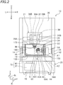
- FIG. 2 is a front view of the cutting apparatus 10, with its front upper cover 20 opened.
- FIG. 3 is a cross-sectional view of the cutting apparatus 10, with the front upper cover 20 closed.
- the following description is based on the assumption that when a user faces the front of the cutting apparatus 10, a direction from the rear of the cutting apparatus 10 toward the user is a forward direction and a direction from the user toward the rear of the cutting apparatus 10 is a rearward direction.
- the terms “right”, “left”, “up”, and “down” respectively refer to right, left, up, and down with respect to the user facing the front of the cutting apparatus 10.
- the reference signs F, Rr, R, L, U, and D in the drawings respectively represent front, rear, right, left, up, and down.
- the cutting apparatus 10 is disposed on a coordinate system including an X axis, a Y axis, and a Z axis perpendicular to each other (which will hereinafter be referred to as an "X, Y, and Z orthogonal coordinate system").
- the X axis extends substantially in a front-rear direction. As illustrated in FIG. 3 , the X axis is inclined relative to a horizontal direction by an angle ⁇ in the present embodiment. Alternatively, the X axis may extend in the horizontal direction.
- the Y axis extends in a right-left direction.
- the Z axis extends substantially in an up-down direction. As illustrated in FIG.
- the Z axis is inclined relative to a vertical direction by the angle ⁇ in the present embodiment.
- the Z axis may extend in the vertical direction.
- the reference sign ⁇ X represents a rotational direction around the X axis.
- the reference sign ⁇ Y represents a rotational direction around the Y axis.
- the reference sign ⁇ Z represents a rotational direction around the Z axis.
- the cutting apparatus 10 cuts a workpiece 5 (see FIG. 4 ).
- the cutting apparatus 10 grinds the workpiece 5 when necessary.
- the cutting apparatus 10 machines the workpiece 5 so as to fabricate a molded article for dental use.
- a molded article include a dental prosthetic (such as a crown, an inlay, an onlay, or a veneer), an artificial tooth, and a denture base.
- the workpiece 5 has a block shape (such as a cubic or cuboid shape).
- the workpiece 5 may have any other suitable shape, such as a disk shape.
- material(s) for the workpiece 5 examples include resin materials (such as polymethyl methacrylate (PMMA) resin, polyether ether ketone (PEEK) resin, and hybrid resin), ceramic materials (such as glass ceramic and zirconia), wax, and gypsum.
- resin materials such as polymethyl methacrylate (PMMA) resin, polyether ether ketone (PEEK) resin, and hybrid resin
- ceramic materials such as glass ceramic and zirconia
- wax gypsum
- gypsum gypsum
- the workpiece 5 is attached to an adapter 8 (which may also be referred to as a "holder") in the present embodiment.
- the workpiece 5 attached to the adapter 8 is held in the cutting apparatus 10.
- the workpiece 5 retained by the adapter 8 is subjected to cutting.
- the adapter 8 includes a plate member 8A and a connecting pin 8B.
- the plate member 8A is attached to the workpiece 5.
- the connecting pin 8B protrudes from the plate member 8A.
- the connecting pin 8B is inserted into an insertion hole 50A defined in a clamp 50 (which will be described below).
- the cutting apparatus 10 is configured such that a coolant is usable during cutting.
- the cutting apparatus 10 is a "wet type" cutting apparatus.
- the term “coolant” may refer to a water-soluble coolant or a water-insoluble coolant.
- the term “coolant” may refer to water or a coolant provided by adding, for example, an additive to water so as to enhance the cooling effect of the water.
- the coolant may consist mainly of water (which is higher in mass percentage than other components) and contain a water-insoluble component (such as mineral oil or grease) and a surfactant.
- the cutting apparatus 10 has a box shape.
- the cutting apparatus 10 includes a case body 12, the front upper cover 20, and a front lower cover 25.
- the case body 12 is a casing of the cutting apparatus 10.
- the case body 12 is hollow.
- the case body 12 includes a bottom wall 13, a left wall 14, a right wall 15, a rear wall 16, an upper wall 17, a front wall 18, a first bottom partition 13S, a right partition 15S, a first rear partition 16S, an upper partition 17S, a second bottom partition 27, and a second rear partition 28.
- the left wall 14 extends upward from the left end of the bottom wall 13.
- the right wall 15 extends upward from the right end of the bottom wall 13.
- the rear wall 16 extends upward from the rear end of the bottom wall 13.
- the left end of the rear wall 16 is connected to the rear end of the left wall 14.
- the right end of the rear wall 16 is connected to the rear end of the right wall 15.
- the front wall 18 extends upward from the front end of the first bottom partition 13S.
- the left end of the front wall 18 is connected to the front end of the left wall 14.
- the right end of the front wall 18 is connected to the front end of the right wall 15.
- the upper end of the front wall 18 is connected to the front end of the upper wall 17.
- the upper wall 17 is connected to the upper ends of the left wall 14, the right wall 15, the rear wall 16, and the front wall 18.
- the first bottom partition 13S is located above the bottom wall 13.
- the first bottom partition 13S extends from the front of the cutting apparatus 10 toward the rear of the cutting apparatus 10 such that the first bottom partition 13S is inclined gradually downward.
- a lid 13L is disposed behind the first bottom partition 13S.
- the lid 13L has a mesh structure that allows the coolant to pass therethrough in the up-down direction.
- the right partition 15S is disposed rightward of the left wall 14 and leftward of the right wall 15.
- the right partition 15S extends upward from the first bottom partition 13S.
- the first rear partition 16S is disposed forward of the rear wall 16 and rearward of the front wall 18.
- the first rear partition 16S is connected to the first bottom partition 13S, the left wall 14, the right partition 15S, and the upper partition 17S.
- the upper partition 17S is disposed above the first bottom partition 13S and below the upper wall 17.
- the second bottom partition 27 is disposed below the first bottom partition 13S and above the bottom wall 13.
- the second bottom partition 27 extends in parallel or substantially in parallel with the bottom wall 13.
- the second bottom partition 27 is provided with a drainage port 27H passing through the second bottom partition 27 in the up-down direction.
- the drainage port 27H is constantly in an open state.
- the drainage port 27H is provided with no switching member (such as a valve element) that enables switching between the open state and closed state.
- the second rear partition 28 is disposed forward of the rear wall 16 and rearward of the front wall 18.
- the second rear partition 28 is disposed below the first rear partition 16S.
- the second rear partition 28 extends in parallel or substantially in parallel with the rear wall 16.
- the second rear partition 28 extends upward from the bottom wall 13.
- the upper end of the second rear partition 28 is connected to the second bottom partition 27.
- a lateral surface of the case body 12 (which is the front wall 18 of the case body 12 in the present embodiment) is provided with an opening 180.
- the opening 180 is defined by the left wall 14, the first bottom partition 13S, the right partition 15S, and the upper partition 17S.
- the internal space of the case body 12 is divided into a right space and a left space by the right partition 15S.
- the left space of the case body 12 defines a machining space 19 surrounded by the left wall 14, the first bottom partition 13S, the right partition 15S, the upper partition 17S, the first rear partition 16S, and the front upper cover 20.
- the machining space 19 is a space where the workpiece 5 is to be cut.
- the right space of the case body 12 defines a first housing space A1 surrounded by the right partition 15S, the first bottom partition 13S, the right wall 15, the upper partition 17S, the first rear partition 16S, and the front wall 18.
- a second housing space A2 is defined below the machining space 19.
- the second housing space A2 is surrounded by the left wall 14, the bottom wall 13, the right wall 15, the second bottom partition 27, the second rear partition 28, and the front lower cover 25.
- the second housing space A2 is in constant communication with the machining space 19 through the drainage port 27H defined in the second bottom partition 27.
- the drainage port 27H is an example of a communication port through which the machining space 19 is in communication with the second housing space A2.
- the front upper cover 20 is supported by support arms 22. An end of each support arm 22 is attached to the case body 12.
- the front upper cover 20 moves in the up-down direction, with each support arm 22 being rotated around its pivot (not illustrated), so as to cover and uncover the opening 180.
- This enables switching between an open state where the opening 180 of the case body 12 is uncovered by the front upper cover 20 and a closed state where the opening 180 of the case body 12 is covered by the front upper cover 20.
- the user moves the front upper cover 20 upward so as to uncover the opening 180 in, for example, placing the workpiece 5 in the cutting apparatus 10, removing the workpiece 5 from the cutting apparatus 10, or performing maintenance of the cutting apparatus 10. Uncovering the opening 180 brings the machining space 19 into communication with an external space.
- the user moves the front upper cover 20 downward so as to cover the opening 180 in carrying out cutting. Covering the opening 180 brings the machining space 19 out of communication with the external space.
- the front upper cover 20 is manually movable in the up-down direction by the user.
- a motor for example, may be connected to the support arms 22, and the motor may be driven so as to automatically move the front upper cover 20 in the up-down direction.
- the front upper cover 20 is provided with a window 21.
- the window 21 is smaller than the opening 180 of the case body 12 when viewed along the X axis.
- the window 21 is made of, for example, a transparent acrylic plate or glass plate. The user would be able to visually check the machining space 19 through the window 21 if the opening 180 is covered by the front upper cover 20 (e.g., during cutting). Because the window 21 is optional, the front upper cover 20 does not necessarily have to be provided with the window 21.
- the front lower cover 25 is slidable in the front-rear direction along a support (not illustrated) attached to the left wall 14 and the right wall 15.
- the movement of the front lower cover 25 in the front-rear direction enables switching between an open state where the second housing space A2 is uncovered by the front lower cover 25 and a closed state where the second housing space A2 is covered by the front lower cover 25.
- the user slides the front lower cover 25 forward in attaching or detaching a storage tank 37 (which stores the coolant) to or from the cutting apparatus 10.
- the user slides the front lower cover 25 rearward in carrying out cutting. Sliding the front lower cover 25 rearward covers the second housing space A2.
- the second housing space A2 may be constantly uncovered.
- the cutting apparatus 10 includes a carriage 38, a tool magazine 40, the clamp 50, a conveyor 58, a liquid collector 70, and a controller 90.
- the carriage 38 is disposed above the machining space 19.
- the carriage 38 is equipped with a spindle 30 and liquid discharge nozzles 36.
- the spindle 30 passes through the upper partition 17S.
- the tool magazine 40 and the clamp 50 are disposed in the machining space 19.
- the conveyor 58 is disposed in the first housing space A1.
- the liquid collector 70 is disposed below the machining space 19.
- the carriage 38 is movable in a Z-axis direction and a Y-axis direction.
- Z-axis direction refers to a direction extending along the Z axis
- Y-axis direction refers to a direction extending along the Y axis.
- the carriage 38 includes a first carriage 38A and a second carriage 38B.
- the first carriage 38A is supported by a pair of first guide shafts 39A extending in the Y-axis direction.
- the first carriage 38A is movable in the Y-axis direction along the first guide shafts 39A by a first driver (not illustrated).
- the left ends of the first guide shafts 39A are connected to the left wall 14.
- the right ends of the first guide shafts 39A pass through the right partition 15S and are connected to the right wall 15.
- the second carriage 38B is supported by a pair of second guide shafts 39B extending in the Z-axis direction.
- the second carriage 38B is movable in the Z-axis direction along the second guide shafts 39B by a second driver (not illustrated).
- the second guide shafts 39B are provided on the first carriage 38A.
- moving the first carriage 38A in the Y-axis direction moves the second carriage 38B in the Y-axis direction accordingly.
- the first driver and the second driver are electrically connected to the controller 90 and controlled by the controller 90.
- the spindle 30 is provided on the second carriage 38B.
- the spindle 30 moves on the X, Y, and Z orthogonal coordinate system in accordance with the movement of the carriage 38. More specifically, the spindle 30 moves in the Z-axis direction in accordance with the movement of the second carriage 38B and moves in the Y-axis direction in accordance with the movement of the first carriage 38A.
- the spindle 30 supports a machining tool 6 such that the machining tool 6 is rotatable.
- the machining tool 6 may be a milling bar.
- the spindle 30 cuts the workpiece 5 by rotating the machining tool 6.
- the spindle 30 includes a gripper 32, a rotator 34, and a seal 35.
- the gripper 32 may be a collet chuck.
- the seal 35 has a cylindrical shape.
- the seal 35 extends in the up-down direction.
- the lower end of the seal 35 is provided with the rotator 34.
- the rotator 34 rotates relative to the seal 35.
- the lower end of the rotator 34 is provided with the gripper 32.
- the gripper 32 rotates together with the rotator 34.
- the gripper 32 supports (or grips) the upper end of the machining tool 6.
- the gripper 32 includes a plurality of supports arranged on an X-Y plane in the present embodiment.
- the gripper 32 supports the machining tool 6 by holding the upper end of the machining tool 6 between the supports.
- the rotator 34 rotates the machining tool 6 supported by the gripper 32.
- the rotator 34 is connected with a first motor (not illustrated).
- the first motor is electrically connected to the controller 90 and controlled by the controller 90. Driving the first motor rotates the rotator 34 in the rotational direction ⁇ Z around the Z axis.
- the machining tool 6 gripped by the gripper 32 rotates in the rotational direction ⁇ Z around the Z axis.
- the liquid discharge nozzles 36 are disposed laterally of the spindle 30. Similarly to the spindle 30, the liquid discharge nozzles 36 move on the X, Y, and Z orthogonal coordinate system in accordance with the movement of the carriage 38. In the present embodiment, the number of liquid discharge nozzles 36 is four in total such that one of the liquid discharge nozzles 36 is disposed in front of the spindle 30, another one of the liquid discharge nozzles 36 is disposed behind the spindle 30, still another one of the liquid discharge nozzles 36 is disposed rightward of the spindle 30, and yet another one of the liquid discharge nozzles 36 is disposed leftward of the spindle 30.
- the liquid discharge nozzles 36 may be disposed at any other suitable locations.
- the carriage 38 may be provided with any other number of liquid discharge nozzles 36.
- the outlets of the liquid discharge nozzles 36 are disposed above the clamp 50 and the machining tool 6. As indicated by the arrows in FIG. 2 , for example, the liquid discharge nozzles 36 discharge the coolant into the machining space 19 while the workpiece 5 is machined with the machining tool 6.
- the liquid discharge nozzles 36 typically discharge the coolant onto the machining tool 6 and/or the workpiece 5.
- Each of the liquid discharge nozzles 36 is an example of a liquid discharger.
- the liquid discharge nozzles 36 are connected to a supply port 37O (see FIG. 7 ) of the storage tank 37 through a liquid supply passage (not illustrated).
- the liquid supply passage may be made of any suitable material and may have any suitable shape and size. In one example, the liquid supply passage is an easily deformable resin tube.
- a liquid supply device, such as a pump, may be disposed at a location somewhere along the liquid supply passage.
- the conveyor 58 moves the tool magazine 40 in an X-axis direction.
- X-axis direction refers to a direction extending along the X axis.
- the conveyor 58 is disposed rightward of the tool magazine 40.
- the conveyor 58 includes a shaft 58A extending in the Y-axis direction.
- the shaft 58A passes through the right partition 15S.
- a portion of the shaft 58A e.g., the right portion of the shaft 58A
- Another portion of the shaft 58A (e.g., the left portion of the shaft 58A) is disposed in the machining space 19.
- the left end of the shaft 58A is provided with the clamp 50 and the tool magazine 40.
- the conveyor 58 is movable in the X-axis direction by a third driver (not illustrated).
- the third driver is electrically connected to the controller 90 and controlled by the controller 90.
- FIG. 5 is a perspective view of the tool magazine 40 and the clamp 50.
- FIG. 6 is a front view of the tool magazine 40 and the clamp 50.
- the tool magazine 40 is able to hold a plurality of the machining tools 6.
- the tool magazine 40 is provided between the clamp 50 and the conveyor 58. Moving the conveyor 58 in the X-axis direction moves the tool magazine 40 in the X-axis direction.
- the tool magazine 40 includes a first portion 40A, a second portion 40B, and a third portion 40C.
- the first portion 40A holds the machining tools 6.
- the second portion 40B is located rearward of the first portion 40A.
- the second portion 40B is connected to the shaft 58A.
- the third portion 40C is located rearward of the second portion 40B.
- the first portion 40A of the tool magazine 40 is provided with a plurality of holes 42 in which the machining tools 6 are to be held.
- the number of holes 42 is six.
- Each machining tool 6 is inserted into an associated one of the holes 42 such that the upper portion of each machining tool 6 is exposed.
- Replacement of the machining tool 6 involves: returning the machining tool 6 gripped by the gripper 32 of the spindle 30 to the associated hole 42; moving the spindle 30 to a position over the machining tool 6 to be used next; and causing the gripper 32 to grip the upper end of the machining tool 6 located under the gripper 32.
- the shaft 58A is internally provided with a rotation shaft 44.
- the rotation shaft 44 supports the clamp 50 such that the clamp 50 is rotatable.
- the rotation shaft 44 extends in the right-left direction.
- the rotation shaft 44 is coupled to the clamp 50 and the conveyor 58.
- a second motor (not illustrated) is provided for the rotation shaft 44.
- the second motor is electrically connected to the controller 90 and controlled by the controller 90.
- the rotation shaft 44 is rotatable in the rotational direction ⁇ Y around the Y axis by the second motor.
- the rotation of the rotation shaft 44 in the rotational direction ⁇ Y around the Y axis causes the clamp 50 to rotate in the rotational direction ⁇ Y around the Y axis.
- the rotation shaft 44 is rotatable independently of the shaft 58A.
- the rotation of the rotation shaft 44 in the rotational direction ⁇ Y around the Y axis thus does not cause the shaft 58A to rotate in the rotational direction ⁇ Y around the Y
- the clamp 50 is a retainer to retain the adapter 8 such that the adapter 8 is detachable from the clamp 50.
- the number of adapters 8 retainable by the clamp 50 is three in the present embodiment.
- the clamp 50 retains the workpiece(s) 5 through the adapter(s) 8.
- the cutting apparatus 10 cuts the workpiece(s) 5 retained by the clamp 50 through the adapter(s) 8.
- the clamp 50 may be configured to directly retain the workpiece(s) 5.
- the clamp 50 is provided with a plurality of the insertion holes 50A. In the present embodiment, the number of insertion holes 50A is three, and the three insertion holes 50A are aligned in the front-rear direction.
- the connecting pins 8B of the adapters 8 are each inserted into an associated one of the insertion holes 50A.
- the connecting pins 8B inserted into the insertion holes 50A are secured to the clamp 50 with screws 50B.
- the clamp 50 is movable together with the tool magazine 40.
- the tool magazine 40 and the clamp 50 are movable in the X-axis direction by the conveyor 58.
- the rotation of the clamp 50 in the rotational direction ⁇ Y around the Y axis does not cause the tool magazine 40 to rotate in the rotational direction ⁇ Y around the Y axis.
- the controller 90 is a computer.
- the controller 90 may include, for example, a central processing unit (CPU), a read-only memory (ROM), a random-access memory (RAM), and a storage medium (such as a memory).
- the CPU executes a command of a control program.
- the ROM stores, for example, the program to be executed by the CPU.
- the RAM is used as a working area where the program is to be expanded.
- the storage medium stores, for example, various data.
- the controller 90 may be programmed and configured to control cutting-related operations using, for example, the program stored in the ROM.
- the controller 90 is disposed in the rear portion of the case body 12. Alternatively, a portion or an entirety of the controller 90 may be disposed outside the case body 12.
- the liquid collector 70 collects at least a portion of the coolant discharged from the liquid discharge nozzles 36.
- the liquid collector 70 includes the storage tank 37, a movable member 80, and an urger 86 (see FIG. 9 ).
- the liquid collector 70 is disposed below the machining space 19.
- the urger 86 secures the movable member 80 to the second bottom partition 27.
- the storage tank 37 and the movable member 80 are disposed below the drainage port 27H defined in the second bottom partition 27.
- the movable member 80 is disposed directly below the drainage port 27H.
- the storage tank 37 and the movable member 80 are disposed in the second housing space A2.
- the storage tank 37 is detachably disposed at a predetermined location in the second housing space A2.
- the movable member 80 is disposed directly above the storage tank 37.
- the movable member 80 is interposed between the drainage port 27H and the storage tank 37.
- FIG. 7 is a perspective view of the storage tank 37.
- the storage tank 37 is hollow.
- the storage tank 37 is a container to collect the coolant discharged from the liquid discharge nozzles 36.
- the storage tank 37 also serves as a container to store the coolant to be used for cutting.
- the storage tank 37 has a flat cuboid shape.
- the storage tank 37 is not limited to any particular shape.
- the storage tank 37 may have, for example, a cylindrical shape, a cubic shape, or a bag shape.
- the storage tank 37 includes a pair of narrow width surfaces 37N.
- the narrow width surfaces 37N face each other in the front-rear direction.
- An opening 37H is defined in the upper portion of the storage tank 37.
- An upper lid 37U is placed in the opening 37H.
- the upper lid 37U is disposed such that the upper lid 37U does not interfere with the movable member 80.
- the upper lid 37U includes a front portion 37F and a rear portion 37Rr.
- the front portion 37F is inclined downward from the front of the upper lid 37U toward the rear of the upper lid 37U when viewed in cross section.
- the rear portion 37Rr is inclined downward from the rear of the upper lid 37U toward the front of the upper lid 37U when viewed in cross section.
- a collection port 371 that passes through the upper lid 37U in the up-down direction is defined between the front portion 37F and the rear portion 37Rr of the upper lid 37U.
- the coolant discharged from the liquid discharge nozzles 36 flows through the drainage port 27H defined in the second bottom partition 27, flows along the movable member 80, and then flows into the storage tank 37 through the collection port 37I of the upper lid 37U. The coolant discharged from the liquid discharge nozzles 36 is thus collected into the storage tank 37.
- the supply port 37O is provided on the rear portion of the storage tank 37.
- the supply port 37O is disposed below the collection port 37I.
- the supply port 37O is formed such that the supply port 37O is fitted to an end of the liquid supply passage.
- the supply port 37O is connected to the end of the liquid supply passage.
- a filter 37A is detachably disposed in the storage tank 37.
- the filter 37A is disposed between the collection port 371 and the supply port 37O.
- the filter 37A filters the coolant collected into the storage tank 37 through the collection port 371.
- the filter 37A removes foreign matter (such as chips or shavings resulting from cutting) from the coolant collected.
- the coolant filtered is delivered to the liquid supply passage through the supply port 37O and then reused for cutting.
- the storage tank 37 is configured such that the coolant collected is re-delivered to the liquid supply passage.
- the storage tank 37 may be configured such that the coolant collected undergoes, for example, disposal without being delivered to the liquid supply passage.
- the storage tank 37 may include no filter 37A.
- FIG. 8 is a perspective view of the movable member 80.
- the movable member 80 is not electrically collected to the controller 90. This enables simple control so as to reduce the load on the controller 90.
- the movable member 80 includes a body 81, a left wall 82, a right wall 83, a vertical partition 84, and a tank contact portion 85.
- the body 81 extends in the front-rear direction.
- the vertical partition 84 divides the body 81 into a front body 81F and a rear body 81Rr.
- the front body 81F and the rear body 81Rr each have a flat plate shape.
- the front body 81F is an example of an inclined portion.
- the left wall 82 extends upward from the left end of the body 81.
- the left wall 82 is provided with threaded holes L1 and L2.
- the right wall 83 extends upward from the right end of the body 81.
- the right wall 83 is provided with threaded holes R1 and R2.
- the threaded hole R1 and the threaded hole L1 are symmetrical.
- the threaded hole R2 and the threaded hole L2 are symmetrical.
- the vertical partition 84 extends upward from the rear end of the front body 81F.
- the front body 81F and the vertical partition 84 are perpendicular or substantially perpendicular to each other when viewed in cross section.
- the left end of the vertical partition 84 is connected to the left wall 82.
- the right end of the vertical partition 84 is connected to the right wall 83.
- the vertical partition 84 is located between the front body 81F and the rear body 81Rr in the front-rear direction.
- the vertical partition 84 has a flat plate shape.
- the tank contact portion 85 extends downward from a rear end 81B2 of the rear body 81 Rr.
- the rear body 81Rr and the tank contact portion 85 are perpendicular or substantially perpendicular to each other when viewed in cross section.
- the tank contact portion 85 has a flat plate shape.
- the tank contact portion 85 may suitably vary in shape in accordance with, for example, the shape of the associated narrow width surface 37N of the storage tank 37.
- the movable member 80 is made of, for example, metal (such as stainless steel, aluminum, iron, or copper) or plastic. In the present embodiment, the components of the movable member 80 are integral with each other. This simplifies the structure of the cutting apparatus 10 so as to reduce the number of components of the cutting apparatus 10 and the number of steps required for assembly of the cutting apparatus 10, resulting in a reduction in manufacturing cost.
- the movable member 80 is provided, for example, by only cutting, drilling, and bending a metal plate.
- the body 81, the vertical partition 84, and the tank contact portion 85 are provided, for example, by only cutting and bending a metal plate. Alternatively, a portion or an entirety of the movable member 80 may include separate components that are assembled to each other. Because the tank contact portion 85 is optional, the movable member 80 may include no tank contact portion 85.
- the body 81 extends substantially straightly in the front-rear direction.
- the width of the body 81 in the right-left direction is equal to or smaller than the width of the collection port 37I of the storage tank 37 in the right-left direction.
- the front body 81F is located directly below the drainage port 27H.
- a front end 81B1 of the front body 81F i.e., an end of the front body 81 F located adjacent to the storage tank 37
- the bent front end 81E extends downward from the front body 81F.
- the bent front end 81E is bent toward the storage tank 37.
- the bent front end 81E is bent at an obtuse bending angle with respect to the front body 81F.
- the inclination of the bent front end 81E relative to the horizontal direction is greater than the inclination of the front body 81 F relative to the horizontal direction.
- the bent front end 81E serves as a coolant passage located between the front body 81F and the storage tank 37. Because the coolant flows along the bent front end 81E, the flow of the coolant will be smoother so as to improve the drainage of the movable member 80.
- the tank contact portion 85 is disposed such that the tank contact portion 85 comes into contact with the associated narrow width surface 37N of the storage tank 37 when the storage tank 37 is inserted into the second housing space A2.
- the tank contact portion 85 is supported by the storage tank 37 when the storage tank 37 is inserted into the second housing space A2.
- the lower end of the tank contact portion 85 is provided with a bent rear end 85E.
- the bent rear end 85E extends rearward from the tank contact portion 85.
- the tank contact portion 85 and the bent rear end 85E are perpendicular or substantially perpendicular to each other when viewed in cross section. Providing the bent rear end 85E enhances the rigidity of the tank contact portion 85.
- the bent rear end 85E makes it difficult for the tank contact portion 85 to damage the storage tank 37, resulting in increased durability of the storage tank 37.
- the user may put his or her hand into the second housing space A2 in, for example, cleaning the second housing space A2. In such a case, the user is able to clean the second housing space A2 without concern for injury to the hand by the tank abutment portion 85 because the tank abutment portion 85 is provided with the bent rear end 85E.
- FIG. 9 is a perspective view of the urger 86.
- the urger 86 is not electrically connected to the controller 90.
- the urger 86 includes a support case 87 and two urging springs (i.e., an urging spring 89L and an urging spring 89R).
- the support case 87 supports the movable member 80 such that the front body 81 F of the movable member 80 is slidable downwardly rearward and the rear body 81 Rr of the movable member 80 is slidable upwardly rearward.
- the left lateral surface of the support case 87 is provided with slide holes 87L1 and 87L2 extending in the front-rear direction.
- the right lateral surface of the support case 87 is provided with slide holes 87R1 and 87R2 extending in the front-rear direction.
- the slide hole 87L1 and the slide hole 87R1 are each in the form of a segment of a circle extending downwardly rearward.
- the slide hole 87L2 and the slide hole 87R2 are each in the form of a segment of a circle extending upwardly rearward.
- the shape of the slide hole 87L1 conforms to the track of the threaded hole L1 during sliding of the movable member 80.
- the shape of the slide hole 87L2 conforms to the track of the threaded hole L2 during sliding of the movable member 80.
- the shape of the slide hole 87R1 conforms to the track of the threaded hole R1 during sliding of the movable member 80.
- the shape of the slide hole 87R2 conforms to the track of the threaded hole R2 during sliding of the movable member 80.
- a bolt 88L1 is inserted through the slide hole 87L1 and the threaded hole L1 of the movable member 80 and fastened with a nut.
- a bolt 88L2 is inserted through the slide hole 87L2 and the threaded hole L2 of the movable member 80 and fastened with a nut.
- a bolt 88R1 is inserted through the slide hole 87R1 and the threaded hole R1 of the movable member 80 and fastened with a nut.
- a bolt 88R2 is inserted through the slide hole 87R2 and the threaded hole R2 of the movable member 80 and fastened with a nut.
- the movable member 80 is thus secured to the support case 87, so that the movable member 80 is integral with the support case 87.
- Each of the bolts 88L1, 88L2, 88R1, and 88R2 is an example of a fixture. Any other suitable fixtures (such as screws, machine screws, or pins) may naturally be used to secure the movable member 80 to the support case 87. Ends of the bolts 88L1 and 88L2 protrude outward from the left lateral surface of the support case 87.
- Ends of the bolts 88R1 and 88R2 protrude outward from the right lateral surface of the support case 87.
- the right and left lateral surfaces of the support case 87 are respectively provided with right and left protrusions 87B protruding outward.
- the urging spring 89L is disposed on the left lateral surface of the support case 87.
- the urging spring 89R is disposed on the right lateral surface of the support case 87.
- a first end of the urging spring 89L is coupled to the left protrusion 87B on the left lateral surface of the support case 87.
- a first end of the urging spring 89R is coupled to the right protrusion 87B on the right lateral surface of the support case 87.
- a second end of the urging spring 89L is coupled to the bolt 88L2 located rearward of the left protrusion 87B.
- a second end of the urging spring 89R is coupled to the bolt 88R2 located rearward of the right protrusion 87B.
- the urging springs 89L and 89R are each disposed to extend substantially in the front-rear direction.
- the front body 81F of the movable member 80 is urged upwardly forward by the spring force (or elastic force) of the urging springs 89L and 89R.
- the urging springs 89L and 89R are helical springs (or coil springs).
- Each of the urging springs 89L and 89R is an example of an urging member.
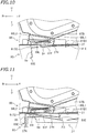
- FIG. 10 is a partial cross-sectional view of the cutting apparatus 10, illustrating components thereof located adjacent to the drainage port 27H when no storage tank 37 is disposed in the second housing space A2.
- FIG. 10 illustrates a partial cross-sectional structure of the cutting apparatus 10 when viewed from its left side.
- the movable member 80 With no storage tank 37 is disposed in the second housing space A2, the movable member 80 is urged by the elastic force of the urging springs 89L and 89R. In this state, the movable member 80 is located at a first position where the front body 81F is relatively close to the bottom of the drainage port 27H.
- the front end 81B1 of the front body 81F is located above the rear end 81B2 of the rear body 81Rr when viewed in cross section.
- the front end 81B1 may be in contact with the second bottom partition 27 or out of contact with the second bottom partition 27.
- the front end 81B1 may be in contact with a portion of the edge of the drainage port 27H or out of contact with a portion of the edge of the drainage port 27H.
- the front body 81F is inclined downwardly rearward when viewed in cross section.
- the front body 81F is inclined away from the bottom wall 13 of the case body 12. With the movable member 80 at the first position, the front body 81F is inclined at an acute angle (e.g., an angle greater than 0 degrees but less than 90 degrees) with respect to the horizontal direction.
- an acute angle e.g., an angle greater than 0 degrees but less than 90 degrees
- the movable member 80 located at the first position functions as a liquid holder to hold the coolant dripping from the drainage port 27H.
- the liquid holder is defined by the front body 81F, the left wall 82, the right wall 83, and the vertical partition 84 of the movable member 80.
- the liquid holder is a recess facing upward.
- a portion of the movable member 80 that functions as the liquid holder is a recess facing the drainage port 27H.
- the front body 81F is located directly below the drainage port 27H. The coolant that has dripped from the drainage port 27H falls on the front body 81F and held by the liquid holder.
- FIG. 11 is a partial cross-sectional view of the cutting apparatus 10, illustrating components thereof located adjacent to the drainage port 27H when the storage tank 37 is disposed in the second housing space A2.
- FIG. 11 illustrates a partial cross-sectional structure of the cutting apparatus 10 when viewed from its left side.
- the rear end 81B2 of the rear body 81Rr is located above the front end 81B1 of the front body 81F when viewed in cross section.
- the rear end 81B2 may be in contact with the second bottom partition 27 or may be out of contact with the second bottom partition 27.
- the front body 81F is inclined downwardly forward when viewed in cross section.
- the front body 81F is inclined toward the collection port 37I of the storage tank 37 when viewed in cross section.
- the inclination of the front body 81F relative to the horizontal direction is smaller than the inclination of the rear portion 37Rr of the storage tank 37 relative to the horizontal direction. This prevents the front body 81F and the upper lid 37U of the storage tank 37 from interfering with each other.
- the movable member 80 located at the second position functions as a guide to guide the coolant into the storage tank 37.
- the guide is defined by the front body 81F and the bent front end 81E.
- the front body 81F is located directly below the drainage port 27H.
- the coolant dripping from the drainage port 27H falls on the front body 81F, flows along the guide, and then drops into the collection port 37I of the storage tank 37.
- the movable member 80 thus functions not only as the liquid holder but also as the guide.
- the user disposes the workpiece 5 and the machining tool 6 at predetermined positions in the machining space 19 so as to cut the workpiece 5 using the cutting apparatus 10.
- the user inserts the storage tank 37 (which stores the coolant) into the second housing space A2 such that the supply port 37O enters the second housing space A2 first. Inserting the storage tank 37 into the second housing space A2 in this manner brings one of the narrow width surfaces 37N of the storage tank 37 into contact with the tank contact portion 85 of the movable member 80. In this state, inserting the storage tank 37 deeper into the second housing space A2 moves the tank contact portion 85 of the movable member 80 upwardly rearward against the elastic force of the urging springs 89L and 89R.
- the front end 81B1 of the movable member 80 moves downward.
- the movable member 80 With the storage tank 37 disposed at a predetermined position in the second housing space A2, the movable member 80 is stably supported by the storage tank 37 and brought to rest at the second position. In this state, the front body 81 F of the movable member 80 is inclined toward the supply port 37O of the storage tank 37.
- the controller 90 controls the cutting apparatus 10 so as to cut the workpiece 5 in accordance with cutting data.
- the controller 90 is connected to, for example, the first driver for the first carriage 38A, the second driver for the second carriage 38B, the third driver for the conveyor 58, the first motor for the spindle 30, the second motor for the clamp 50, and the liquid discharge nozzles 36.
- the controller 90 thus suitably controls the first driver, the second driver, the third driver, the first motor, the second motor, and the liquid discharge nozzles 36.
- the controller 90 controls the cutting apparatus 10 so as to cut the workpiece 5 while three-dimensionally changing the relative positions of the workpiece 5 retained by the clamp 50 and the machining tool 6 gripped by the gripper 32.
- the controller 90 causes the liquid discharge nozzles 36 to discharge the coolant when necessary.
- the coolant discharged from the liquid discharge nozzles 36 during cutting flows downward through the drainage port 27H, flows along the guide defined by at least a portion of the movable member 80, and is then collected into the storage tank 37.
- the user When repetition of cutting has contaminated the coolant in the storage tank 37 or reduced the amount of the coolant in the storage tank 37, the user removes the storage tank 37 from the second housing space A2.
- the removal of the storage tank 37 by the user brings the tank contact portion 85 of the movable member 80 out of contact with the associated narrow width surface 37N of the storage tank 37.
- the elastic force of the urging springs 89L and 89R thus causes the tank contact portion 85 of the movable member 80 to move downwardly forward and causes the front end 81B1 to move upward. This brings the movable member 80 to rest at the first position. Consequently, the front body 81F of the movable member 80 is inclined away from the bottom wall 13 of the case body 12.
- the coolant dripping from the drainage port 27H accumulates in the liquid holder defined by at least a portion of the movable member 80.
- the coolant that has accumulated in the liquid holder is collected into the storage tank 37. Insertion of the storage tank 37 into the second housing space A2 by the user moves the front body 81F of the movable member 80 in a seesaw-like manner.
- the movable member 80 moves from a state where the front end 81B1 of the front body 81F is located above the rear end 81 B2 of the rear body 81Rr to a state where the rear end 81B2 of the rear body 81Rr is located above the front end 81 B1 of the front body 81 F.
- the coolant that has accumulated in the liquid holder thus flows along the guide and is then collected into the storage tank 37.
- the movable member 80 moves the movable member 80 to the first position, so that the liquid holder is located under the drainage port 27H.
- the liquid holder is defined by the front body 81F, the left wall 82, the right wall 83, and the vertical partition 84 of the movable member 80.
- the movable member 80 of the cutting apparatus 10 functions as the guide to guide the coolant into the storage tank 37 when the movable member 80 is located at the second position.
- the guide is defined by the front body 81F and the bent front end 81E continuous with each other. The coolant is thus more unlikely to splash or spatter between the drainage port 27H and the storage tank 37 than when, for example, no guide is provided. Consequently, the coolant is more reliably collected into the storage tank 37.
- the cutting apparatus 10 is configured such that the coolant is held by the liquid holder when the movable member 80 is located at the first position, and the coolant is guided into the storage tank 37 by the guide when the movable member 80 is located at the second position. This enhances the efficiency of collecting the coolant so as to reuse the coolant without any waste.
- the movable member 80 of the cutting apparatus 10 includes the inclined portion disposed directly below the drainage port 27H.
- the inclined portion is the front body 81F.
- the inclination of the front body 81F of the movable member 80 at the first position is opposite in direction to the inclination of the front body 81F of the movable member 80 at the second position when viewed in cross section.
- the movable member 80 of the cutting apparatus 10 is moved from the first position to the second position by attaching of the storage tank 37 to the cutting apparatus 10 by the user. This eliminates the need for a driver to move the movable member 80 between the first position and the second position.
- the cutting apparatus 10 is thus further simplified in structure.
- the cutting apparatus 10 includes the urging springs 89L and 89R to urge the movable member 80 to the first position.
- the movable member 80 is thus reliably maintained at the first position when the storage tank 37 is not disposed in the second housing space A2.
- the movable member 80 of the cutting apparatus 10 includes the bent front end 81E that is provided on an end of the movable member 80 adjacent to the storage tank 37 and is bent toward the storage tank 37, with the storage tank 37 disposed in the second housing space A2.
- the bent front end 81E functions as a portion of the guide.
- the bent front end 81E functions as a coolant passage between the front body 81F and the storage tank 37. This makes the flow of the coolant smoother so as to improve the drainage of the movable member 80.
- the machining space 19 and the second housing space A2 of the cutting apparatus 10 according to the present embodiment are in constant communication with each other through the drainage port 27H.
- the body 81 (or more specifically, the front body 81F), the left wall 82, the right wall 83, the vertical partition 84, and the tank contact portion 85 of the movable member 80 each have, for example, a flat plate shape when viewed in cross section.
- Each of these components of the movable member 80 may have any other suitable shape.
- the front body 81F may have, for example, a V shape or a U shape in a cross section taken in the right-left direction, such that the right and left portions of the front body 81F extend downward toward the center of the front body 81F in the right-left direction.
- the movable member 80 is moved from the first position to the second position by attaching of the storage tank 37 to the cutting apparatus 10 by the user.
- the movable member 80 may be moved from the first position to the second position in any other suitable manner.
- the movable member 80 may be electrically connected to the controller 90 and moved from the first position to the second position upon receiving a signal from the controller 90.
- a sensor to detect whether the storage tank 37 is disposed in the second housing space A2 may be provided, for example, on the bottom of the second housing space A2.
- the sensor may be, for example, a contact sensor (such as a weight sensor) or a non-contact sensor (such as a photosensor).
- the movable member 80 may move from the first position to the second position upon determination by the controller 90 that the storage tank 37 is disposed in the second housing space A2 in accordance with a signal transmitted to the controller 90 from the sensor.
Landscapes
- Health & Medical Sciences (AREA)
- Engineering & Computer Science (AREA)
- Mechanical Engineering (AREA)
- Oral & Maxillofacial Surgery (AREA)
- Dentistry (AREA)
- Epidemiology (AREA)
- Life Sciences & Earth Sciences (AREA)
- Animal Behavior & Ethology (AREA)
- General Health & Medical Sciences (AREA)
- Public Health (AREA)
- Veterinary Medicine (AREA)
- Auxiliary Devices For Machine Tools (AREA)
Description
- The present invention relates to a cutting apparatus according to the preamble of
claim 1. DocumentKR-A 2010 0061884 - Cutting apparatuses known in the related art cut ceramic or resin workpieces into desired shapes. Such a cutting apparatus includes, for example, a case body, a retainer, and a gripper. A machining space is defined in the case body. The retainer is disposed in the machining space and retains a workpiece. The gripper is disposed in the machining space and grips a machining tool to carry out machining (e.g., cutting and/or grinding) on the workpiece.
- During cutting, friction occurs between the workpiece and the machining tool. An increase in frictional force resulting from the friction may require a greater cutting force during cutting. Heat caused by the friction may deform the workpiece or may promote wearing away of the machining tool. To solve these problems,
JP 2016-135519 A - The storage tank of the cutting apparatus disclosed in
JP 2016-135519 A - Accordingly, the problem to be solved by the present invention is to provide a cutting apparatus whose internal space is unlikely to be contaminated with a coolant when a storage tank is detached from the cutting apparatus.
- The above problem is solved with a cutting apparatus comprising the features of
claim 1. The cutting apparatus according to the present invention includes a case body, a retainer, a gripper, a liquid discharger, a storage tank, and a movable member. The case body internally includes a machining space, a housing space located below the machining space, and a communication port through which the machining space is in communication with the housing space. The retainer is disposed in the machining space. The retainer retains a workpiece. The gripper is disposed in the machining space. The gripper grips a machining tool to cut the workpiece. The liquid discharger discharges a coolant into the machining space. The storage tank is detachably disposed in the housing space. The storage tank collects the coolant discharged from the liquid discharger and passed through the communication port. The movable member is disposed between the communication port and the storage tank. The movable member is located at a first position when the storage tank is not disposed in the housing space. The movable member is located at a second position when the storage tank is disposed in the housing space. The movable member located at the first position functions as a liquid holder to hold the coolant. - Preferably, the liquid holder defined by at least a portion of the movable member is located under the communication port when the storage tank is not disposed in the housing space. Thus, if the coolant remains, for example, on the edge of the communication port and droplets of the coolant drip when the storage tank is detached from the cutting apparatus, the droplets would accumulate in the liquid holder. This prevents the droplets of the coolant from dripping into the housing space and thus makes it unlikely that the housing space will be contaminated with the coolant. Consequently, the housing space is kept in a clean state.
- The present invention provides a cutting apparatus whose internal space is unlikely to be contaminated with a coolant when a storage tank is detached from the cutting apparatus.
-
-
FIG. 1 is a perspective view of a cutting apparatus according to an embodiment of the present invention. -
FIG. 2 is a front view of the cutting apparatus illustrated inFIG. 1 , with its front upper cover opened. -
FIG. 3 is a cross-sectional view of the cutting apparatus illustrated inFIG. 1 , with its front upper cover closed. -
FIG. 4 is a perspective view of a workpiece attached to an adapter according to the embodiment of the present invention. -
FIG. 5 is a perspective view of a tool magazine and a clamp according to the embodiment of the present invention. -
FIG. 6 is a front view of the tool magazine and the clamp according to the embodiment of the present invention. -
FIG. 7 is a perspective view of a storage tank according to the embodiment of the present invention. -
FIG. 8 is a perspective view of a movable member according to the embodiment of the present invention. -
FIG. 9 is a perspective view of an urger according to the embodiment of the present invention. -
FIG. 10 is a partial cross-sectional view of the cutting apparatus, illustrating components thereof located adjacent to a drainage port when the storage tank is not disposed in the cutting apparatus. -
FIG. 11 is a partial cross-sectional view of the cutting apparatus, illustrating components thereof located adjacent to the drainage port when the storage tank is disposed in the cutting apparatus. - Cutting apparatuses according to embodiments of the present invention will be described below with reference to the drawings. The embodiments described below are naturally not intended to limit the present invention in any way. Components or elements having the same functions are identified by the same reference signs, and description thereof will be simplified or omitted when deemed redundant.
-
FIG. 1 is a perspective view of a cuttingapparatus 10.FIG. 2 is a front view of the cuttingapparatus 10, with its frontupper cover 20 opened.FIG. 3 is a cross-sectional view of the cuttingapparatus 10, with the frontupper cover 20 closed. The following description is based on the assumption that when a user faces the front of the cuttingapparatus 10, a direction from the rear of the cuttingapparatus 10 toward the user is a forward direction and a direction from the user toward the rear of the cuttingapparatus 10 is a rearward direction. The terms "right", "left", "up", and "down" respectively refer to right, left, up, and down with respect to the user facing the front of the cuttingapparatus 10. The reference signs F, Rr, R, L, U, and D in the drawings respectively represent front, rear, right, left, up, and down. - The cutting
apparatus 10 is disposed on a coordinate system including an X axis, a Y axis, and a Z axis perpendicular to each other (which will hereinafter be referred to as an "X, Y, and Z orthogonal coordinate system"). The X axis extends substantially in a front-rear direction. As illustrated inFIG. 3 , the X axis is inclined relative to a horizontal direction by an angle θ in the present embodiment. Alternatively, the X axis may extend in the horizontal direction. The Y axis extends in a right-left direction. The Z axis extends substantially in an up-down direction. As illustrated inFIG. 3 , the Z axis is inclined relative to a vertical direction by the angle θ in the present embodiment. Alternatively, the Z axis may extend in the vertical direction. The reference sign θX represents a rotational direction around the X axis. The reference sign θY represents a rotational direction around the Y axis. The reference sign θZ represents a rotational direction around the Z axis. These directions are defined merely for the sake of convenience of description and do not limit in any way how the cuttingapparatus 10 may be installed. These directions do not limit the present invention in any way. - The cutting
apparatus 10 cuts a workpiece 5 (seeFIG. 4 ). The cuttingapparatus 10 grinds theworkpiece 5 when necessary. The cuttingapparatus 10 machines theworkpiece 5 so as to fabricate a molded article for dental use. Examples of such a molded article include a dental prosthetic (such as a crown, an inlay, an onlay, or a veneer), an artificial tooth, and a denture base. In the present embodiment, theworkpiece 5 has a block shape (such as a cubic or cuboid shape). Alternatively, theworkpiece 5 may have any other suitable shape, such as a disk shape. Examples of material(s) for theworkpiece 5 include resin materials (such as polymethyl methacrylate (PMMA) resin, polyether ether ketone (PEEK) resin, and hybrid resin), ceramic materials (such as glass ceramic and zirconia), wax, and gypsum. When zirconia is selected as a material for theworkpiece 5, semi-sintered zirconia, for example, is used. Theworkpiece 5 is not limited to any particular shape or material. - As illustrated in
FIG. 4 , theworkpiece 5 is attached to an adapter 8 (which may also be referred to as a "holder") in the present embodiment. Theworkpiece 5 attached to theadapter 8 is held in the cuttingapparatus 10. Theworkpiece 5 retained by theadapter 8 is subjected to cutting. Theadapter 8 includes aplate member 8A and a connectingpin 8B. Theplate member 8A is attached to theworkpiece 5. The connectingpin 8B protrudes from theplate member 8A. The connectingpin 8B is inserted into aninsertion hole 50A defined in a clamp 50 (which will be described below). - The cutting
apparatus 10 is configured such that a coolant is usable during cutting. The cuttingapparatus 10 is a "wet type" cutting apparatus. As used herein, the term "coolant" may refer to a water-soluble coolant or a water-insoluble coolant. The term "coolant" may refer to water or a coolant provided by adding, for example, an additive to water so as to enhance the cooling effect of the water. In one example, the coolant may consist mainly of water (which is higher in mass percentage than other components) and contain a water-insoluble component (such as mineral oil or grease) and a surfactant. - As illustrated in
FIGS. 1 to 3 , the cuttingapparatus 10 has a box shape. The cuttingapparatus 10 includes acase body 12, the frontupper cover 20, and a frontlower cover 25. Thecase body 12 is a casing of the cuttingapparatus 10. Thecase body 12 is hollow. Thecase body 12 includes abottom wall 13, aleft wall 14, aright wall 15, arear wall 16, anupper wall 17, afront wall 18, afirst bottom partition 13S, aright partition 15S, a firstrear partition 16S, anupper partition 17S, asecond bottom partition 27, and a secondrear partition 28. Theleft wall 14 extends upward from the left end of thebottom wall 13. Theright wall 15 extends upward from the right end of thebottom wall 13. Therear wall 16 extends upward from the rear end of thebottom wall 13. The left end of therear wall 16 is connected to the rear end of theleft wall 14. The right end of therear wall 16 is connected to the rear end of theright wall 15. Thefront wall 18 extends upward from the front end of thefirst bottom partition 13S. The left end of thefront wall 18 is connected to the front end of theleft wall 14. The right end of thefront wall 18 is connected to the front end of theright wall 15. The upper end of thefront wall 18 is connected to the front end of theupper wall 17. Theupper wall 17 is connected to the upper ends of theleft wall 14, theright wall 15, therear wall 16, and thefront wall 18. - The
first bottom partition 13S is located above thebottom wall 13. Thefirst bottom partition 13S extends from the front of the cuttingapparatus 10 toward the rear of the cuttingapparatus 10 such that thefirst bottom partition 13S is inclined gradually downward. Alid 13L is disposed behind thefirst bottom partition 13S. Thelid 13L has a mesh structure that allows the coolant to pass therethrough in the up-down direction. Theright partition 15S is disposed rightward of theleft wall 14 and leftward of theright wall 15. Theright partition 15S extends upward from thefirst bottom partition 13S. The firstrear partition 16S is disposed forward of therear wall 16 and rearward of thefront wall 18. The firstrear partition 16S is connected to thefirst bottom partition 13S, theleft wall 14, theright partition 15S, and theupper partition 17S. Theupper partition 17S is disposed above thefirst bottom partition 13S and below theupper wall 17. - The
second bottom partition 27 is disposed below thefirst bottom partition 13S and above thebottom wall 13. Thesecond bottom partition 27 extends in parallel or substantially in parallel with thebottom wall 13. Thesecond bottom partition 27 is provided with adrainage port 27H passing through thesecond bottom partition 27 in the up-down direction. Thedrainage port 27H is constantly in an open state. Thedrainage port 27H is provided with no switching member (such as a valve element) that enables switching between the open state and closed state. The secondrear partition 28 is disposed forward of therear wall 16 and rearward of thefront wall 18. The secondrear partition 28 is disposed below the firstrear partition 16S. The secondrear partition 28 extends in parallel or substantially in parallel with therear wall 16. The secondrear partition 28 extends upward from thebottom wall 13. The upper end of the secondrear partition 28 is connected to thesecond bottom partition 27. - A lateral surface of the case body 12 (which is the
front wall 18 of thecase body 12 in the present embodiment) is provided with anopening 180. Theopening 180 is defined by theleft wall 14, thefirst bottom partition 13S, theright partition 15S, and theupper partition 17S. The internal space of thecase body 12 is divided into a right space and a left space by theright partition 15S. The left space of thecase body 12 defines amachining space 19 surrounded by theleft wall 14, thefirst bottom partition 13S, theright partition 15S, theupper partition 17S, the firstrear partition 16S, and the frontupper cover 20. Themachining space 19 is a space where theworkpiece 5 is to be cut. The right space of thecase body 12 defines a first housing space A1 surrounded by theright partition 15S, thefirst bottom partition 13S, theright wall 15, theupper partition 17S, the firstrear partition 16S, and thefront wall 18. A second housing space A2 is defined below themachining space 19. The second housing space A2 is surrounded by theleft wall 14, thebottom wall 13, theright wall 15, thesecond bottom partition 27, the secondrear partition 28, and the frontlower cover 25. The second housing space A2 is in constant communication with themachining space 19 through thedrainage port 27H defined in thesecond bottom partition 27. Thedrainage port 27H is an example of a communication port through which themachining space 19 is in communication with the second housing space A2. - The front
upper cover 20 is supported bysupport arms 22. An end of eachsupport arm 22 is attached to thecase body 12. The frontupper cover 20 moves in the up-down direction, with eachsupport arm 22 being rotated around its pivot (not illustrated), so as to cover and uncover theopening 180. This enables switching between an open state where theopening 180 of thecase body 12 is uncovered by the frontupper cover 20 and a closed state where theopening 180 of thecase body 12 is covered by the frontupper cover 20. The user moves the frontupper cover 20 upward so as to uncover theopening 180 in, for example, placing theworkpiece 5 in the cuttingapparatus 10, removing theworkpiece 5 from the cuttingapparatus 10, or performing maintenance of the cuttingapparatus 10. Uncovering theopening 180 brings themachining space 19 into communication with an external space. The user moves the frontupper cover 20 downward so as to cover theopening 180 in carrying out cutting. Covering theopening 180 brings themachining space 19 out of communication with the external space. In the present embodiment, the frontupper cover 20 is manually movable in the up-down direction by the user. Alternatively, a motor, for example, may be connected to thesupport arms 22, and the motor may be driven so as to automatically move the frontupper cover 20 in the up-down direction. - The front
upper cover 20 is provided with awindow 21. Thewindow 21 is smaller than theopening 180 of thecase body 12 when viewed along the X axis. Thewindow 21 is made of, for example, a transparent acrylic plate or glass plate. The user would be able to visually check themachining space 19 through thewindow 21 if theopening 180 is covered by the front upper cover 20 (e.g., during cutting). Because thewindow 21 is optional, the frontupper cover 20 does not necessarily have to be provided with thewindow 21. - The front
lower cover 25 is slidable in the front-rear direction along a support (not illustrated) attached to theleft wall 14 and theright wall 15. The movement of the frontlower cover 25 in the front-rear direction enables switching between an open state where the second housing space A2 is uncovered by the frontlower cover 25 and a closed state where the second housing space A2 is covered by the frontlower cover 25. The user slides the frontlower cover 25 forward in attaching or detaching a storage tank 37 (which stores the coolant) to or from the cuttingapparatus 10. The user slides the frontlower cover 25 rearward in carrying out cutting. Sliding the frontlower cover 25 rearward covers the second housing space A2. Covering the second housing space A2 during cutting prevents the user from removing thestorage tank 37 by mistake in the course of cutting theworkpiece 5. Because the frontlower cover 25 is optional, the cuttingapparatus 10 does not necessarily have to include the frontlower cover 25. The second housing space A2 may be constantly uncovered. - The cutting
apparatus 10 includes acarriage 38, atool magazine 40, theclamp 50, aconveyor 58, aliquid collector 70, and acontroller 90. Thecarriage 38 is disposed above themachining space 19. Thecarriage 38 is equipped with aspindle 30 andliquid discharge nozzles 36. Thespindle 30 passes through theupper partition 17S. Thetool magazine 40 and theclamp 50 are disposed in themachining space 19. Theconveyor 58 is disposed in the first housing space A1. Theliquid collector 70 is disposed below themachining space 19. - The
carriage 38 is movable in a Z-axis direction and a Y-axis direction. As used herein, the term "Z-axis direction" refers to a direction extending along the Z axis, and the term "Y-axis direction" refers to a direction extending along the Y axis. Thecarriage 38 includes afirst carriage 38A and asecond carriage 38B. Thefirst carriage 38A is supported by a pair offirst guide shafts 39A extending in the Y-axis direction. Thefirst carriage 38A is movable in the Y-axis direction along thefirst guide shafts 39A by a first driver (not illustrated). The left ends of thefirst guide shafts 39A are connected to theleft wall 14. The right ends of thefirst guide shafts 39A pass through theright partition 15S and are connected to theright wall 15. Thesecond carriage 38B is supported by a pair ofsecond guide shafts 39B extending in the Z-axis direction. Thesecond carriage 38B is movable in the Z-axis direction along thesecond guide shafts 39B by a second driver (not illustrated). Thesecond guide shafts 39B are provided on thefirst carriage 38A. Thus, moving thefirst carriage 38A in the Y-axis direction moves thesecond carriage 38B in the Y-axis direction accordingly. The first driver and the second driver are electrically connected to thecontroller 90 and controlled by thecontroller 90. - The
spindle 30 is provided on thesecond carriage 38B. Thespindle 30 moves on the X, Y, and Z orthogonal coordinate system in accordance with the movement of thecarriage 38. More specifically, thespindle 30 moves in the Z-axis direction in accordance with the movement of thesecond carriage 38B and moves in the Y-axis direction in accordance with the movement of thefirst carriage 38A. Thespindle 30 supports amachining tool 6 such that themachining tool 6 is rotatable. Themachining tool 6 may be a milling bar. Thespindle 30 cuts theworkpiece 5 by rotating themachining tool 6. Thespindle 30 includes agripper 32, arotator 34, and aseal 35. In one example, thegripper 32 may be a collet chuck. Theseal 35 has a cylindrical shape. Theseal 35 extends in the up-down direction. The lower end of theseal 35 is provided with therotator 34. Therotator 34 rotates relative to theseal 35. - The lower end of the
rotator 34 is provided with thegripper 32. Thegripper 32 rotates together with therotator 34. Thegripper 32 supports (or grips) the upper end of themachining tool 6. Although not illustrated, thegripper 32 includes a plurality of supports arranged on an X-Y plane in the present embodiment. Thegripper 32 supports themachining tool 6 by holding the upper end of themachining tool 6 between the supports. Therotator 34 rotates themachining tool 6 supported by thegripper 32. Therotator 34 is connected with a first motor (not illustrated). The first motor is electrically connected to thecontroller 90 and controlled by thecontroller 90. Driving the first motor rotates therotator 34 in the rotational direction θZ around the Z axis. In accordance with the rotation of therotator 34, themachining tool 6 gripped by thegripper 32 rotates in the rotational direction θZ around the Z axis. - The
liquid discharge nozzles 36 are disposed laterally of thespindle 30. Similarly to thespindle 30, theliquid discharge nozzles 36 move on the X, Y, and Z orthogonal coordinate system in accordance with the movement of thecarriage 38. In the present embodiment, the number ofliquid discharge nozzles 36 is four in total such that one of theliquid discharge nozzles 36 is disposed in front of thespindle 30, another one of theliquid discharge nozzles 36 is disposed behind thespindle 30, still another one of theliquid discharge nozzles 36 is disposed rightward of thespindle 30, and yet another one of theliquid discharge nozzles 36 is disposed leftward of thespindle 30. Theliquid discharge nozzles 36 may be disposed at any other suitable locations. Thecarriage 38 may be provided with any other number ofliquid discharge nozzles 36. The outlets of theliquid discharge nozzles 36 are disposed above theclamp 50 and themachining tool 6. As indicated by the arrows inFIG. 2 , for example, theliquid discharge nozzles 36 discharge the coolant into themachining space 19 while theworkpiece 5 is machined with themachining tool 6. Theliquid discharge nozzles 36 typically discharge the coolant onto themachining tool 6 and/or theworkpiece 5. Each of theliquid discharge nozzles 36 is an example of a liquid discharger. Theliquid discharge nozzles 36 are connected to a supply port 37O (seeFIG. 7 ) of thestorage tank 37 through a liquid supply passage (not illustrated). The liquid supply passage may be made of any suitable material and may have any suitable shape and size. In one example, the liquid supply passage is an easily deformable resin tube. A liquid supply device, such as a pump, may be disposed at a location somewhere along the liquid supply passage. - The
conveyor 58 moves thetool magazine 40 in an X-axis direction. As used herein, the term "X-axis direction" refers to a direction extending along the X axis. Theconveyor 58 is disposed rightward of thetool magazine 40. Theconveyor 58 includes ashaft 58A extending in the Y-axis direction. Theshaft 58A passes through theright partition 15S. A portion of theshaft 58A (e.g., the right portion of theshaft 58A) is disposed in the first housing space A1. Another portion of theshaft 58A (e.g., the left portion of theshaft 58A) is disposed in themachining space 19. The left end of theshaft 58A is provided with theclamp 50 and thetool magazine 40. Theconveyor 58 is movable in the X-axis direction by a third driver (not illustrated). The third driver is electrically connected to thecontroller 90 and controlled by thecontroller 90. -
FIG. 5 is a perspective view of thetool magazine 40 and theclamp 50.FIG. 6 is a front view of thetool magazine 40 and theclamp 50. Thetool magazine 40 is able to hold a plurality of themachining tools 6. Thetool magazine 40 is provided between theclamp 50 and theconveyor 58. Moving theconveyor 58 in the X-axis direction moves thetool magazine 40 in the X-axis direction. Thetool magazine 40 includes afirst portion 40A, asecond portion 40B, and athird portion 40C. Thefirst portion 40A holds themachining tools 6. Thesecond portion 40B is located rearward of thefirst portion 40A. Thesecond portion 40B is connected to theshaft 58A. Thethird portion 40C is located rearward of thesecond portion 40B. Thefirst portion 40A of thetool magazine 40 is provided with a plurality ofholes 42 in which themachining tools 6 are to be held. In the present embodiment, the number ofholes 42 is six. Eachmachining tool 6 is inserted into an associated one of theholes 42 such that the upper portion of eachmachining tool 6 is exposed. Replacement of themachining tool 6 involves: returning themachining tool 6 gripped by thegripper 32 of thespindle 30 to the associatedhole 42; moving thespindle 30 to a position over themachining tool 6 to be used next; and causing thegripper 32 to grip the upper end of themachining tool 6 located under thegripper 32. - The
shaft 58A is internally provided with arotation shaft 44. Therotation shaft 44 supports theclamp 50 such that theclamp 50 is rotatable. Therotation shaft 44 extends in the right-left direction. Therotation shaft 44 is coupled to theclamp 50 and theconveyor 58. A second motor (not illustrated) is provided for therotation shaft 44. The second motor is electrically connected to thecontroller 90 and controlled by thecontroller 90. Therotation shaft 44 is rotatable in the rotational direction θY around the Y axis by the second motor. The rotation of therotation shaft 44 in the rotational direction θY around the Y axis causes theclamp 50 to rotate in the rotational direction θY around the Y axis. Therotation shaft 44 is rotatable independently of theshaft 58A. The rotation of therotation shaft 44 in the rotational direction θY around the Y axis thus does not cause theshaft 58A to rotate in the rotational direction θY around the Y axis. - The
clamp 50 is a retainer to retain theadapter 8 such that theadapter 8 is detachable from theclamp 50. As illustrated inFIG. 5 , the number ofadapters 8 retainable by theclamp 50 is three in the present embodiment. In the present embodiment, theclamp 50 retains the workpiece(s) 5 through the adapter(s) 8. The cuttingapparatus 10 according to the present embodiment cuts the workpiece(s) 5 retained by theclamp 50 through the adapter(s) 8. Alternatively, theclamp 50 may be configured to directly retain the workpiece(s) 5. Theclamp 50 is provided with a plurality of the insertion holes 50A. In the present embodiment, the number ofinsertion holes 50A is three, and the threeinsertion holes 50A are aligned in the front-rear direction. The connecting pins 8B of theadapters 8 are each inserted into an associated one of the insertion holes 50A. The connecting pins 8B inserted into the insertion holes 50A are secured to theclamp 50 withscrews 50B. Theclamp 50 is movable together with thetool magazine 40. Thetool magazine 40 and theclamp 50 are movable in the X-axis direction by theconveyor 58. The rotation of theclamp 50 in the rotational direction θY around the Y axis does not cause thetool magazine 40 to rotate in the rotational direction θY around the Y axis. - In one example, the
controller 90 is a computer. Thecontroller 90 may include, for example, a central processing unit (CPU), a read-only memory (ROM), a random-access memory (RAM), and a storage medium (such as a memory). The CPU executes a command of a control program. The ROM stores, for example, the program to be executed by the CPU. The RAM is used as a working area where the program is to be expanded. The storage medium stores, for example, various data. Thecontroller 90 may be programmed and configured to control cutting-related operations using, for example, the program stored in the ROM. In the present embodiment, thecontroller 90 is disposed in the rear portion of thecase body 12. Alternatively, a portion or an entirety of thecontroller 90 may be disposed outside thecase body 12. - The
liquid collector 70 collects at least a portion of the coolant discharged from theliquid discharge nozzles 36. Theliquid collector 70 includes thestorage tank 37, amovable member 80, and an urger 86 (seeFIG. 9 ). Theliquid collector 70 is disposed below themachining space 19. Theurger 86 secures themovable member 80 to thesecond bottom partition 27. Thestorage tank 37 and themovable member 80 are disposed below thedrainage port 27H defined in thesecond bottom partition 27. Themovable member 80 is disposed directly below thedrainage port 27H. Thestorage tank 37 and themovable member 80 are disposed in the second housing space A2. Thestorage tank 37 is detachably disposed at a predetermined location in the second housing space A2. Themovable member 80 is disposed directly above thestorage tank 37. Themovable member 80 is interposed between thedrainage port 27H and thestorage tank 37. -
FIG. 7 is a perspective view of thestorage tank 37. Thestorage tank 37 is hollow. Thestorage tank 37 is a container to collect the coolant discharged from theliquid discharge nozzles 36. In the present embodiment, thestorage tank 37 also serves as a container to store the coolant to be used for cutting. In the present embodiment, thestorage tank 37 has a flat cuboid shape. Thestorage tank 37, however, is not limited to any particular shape. Thestorage tank 37 may have, for example, a cylindrical shape, a cubic shape, or a bag shape. Thestorage tank 37 includes a pair ofnarrow width surfaces 37N. Thenarrow width surfaces 37N face each other in the front-rear direction. - An
opening 37H is defined in the upper portion of thestorage tank 37. Anupper lid 37U is placed in theopening 37H. Theupper lid 37U is disposed such that theupper lid 37U does not interfere with themovable member 80. Theupper lid 37U includes afront portion 37F and a rear portion 37Rr. Thefront portion 37F is inclined downward from the front of theupper lid 37U toward the rear of theupper lid 37U when viewed in cross section. The rear portion 37Rr is inclined downward from the rear of theupper lid 37U toward the front of theupper lid 37U when viewed in cross section. Acollection port 371 that passes through theupper lid 37U in the up-down direction is defined between thefront portion 37F and the rear portion 37Rr of theupper lid 37U. The coolant discharged from theliquid discharge nozzles 36 flows through thedrainage port 27H defined in thesecond bottom partition 27, flows along themovable member 80, and then flows into thestorage tank 37 through the collection port 37I of theupper lid 37U. The coolant discharged from theliquid discharge nozzles 36 is thus collected into thestorage tank 37. - The supply port 37O is provided on the rear portion of the
storage tank 37. The supply port 37O is disposed below the collection port 37I. The supply port 37O is formed such that the supply port 37O is fitted to an end of the liquid supply passage. The supply port 37O is connected to the end of the liquid supply passage. Afilter 37A is detachably disposed in thestorage tank 37. Thefilter 37A is disposed between thecollection port 371 and the supply port 37O. Thefilter 37A filters the coolant collected into thestorage tank 37 through thecollection port 371. In one example, thefilter 37A removes foreign matter (such as chips or shavings resulting from cutting) from the coolant collected. The coolant filtered is delivered to the liquid supply passage through the supply port 37O and then reused for cutting. In the present embodiment, thestorage tank 37 is configured such that the coolant collected is re-delivered to the liquid supply passage. Alternatively, thestorage tank 37 may be configured such that the coolant collected undergoes, for example, disposal without being delivered to the liquid supply passage. In such a case, thestorage tank 37 may include nofilter 37A. -
FIG. 8 is a perspective view of themovable member 80. Themovable member 80 is not electrically collected to thecontroller 90. This enables simple control so as to reduce the load on thecontroller 90. Themovable member 80 includes abody 81, aleft wall 82, aright wall 83, avertical partition 84, and atank contact portion 85. Thebody 81 extends in the front-rear direction. Thevertical partition 84 divides thebody 81 into afront body 81F and a rear body 81Rr. In the present embodiment, thefront body 81F and the rear body 81Rr each have a flat plate shape. Thefront body 81F is an example of an inclined portion. Theleft wall 82 extends upward from the left end of thebody 81. Theleft wall 82 is provided with threaded holes L1 and L2. Theright wall 83 extends upward from the right end of thebody 81. Theright wall 83 is provided with threaded holes R1 and R2. The threaded hole R1 and the threaded hole L1 are symmetrical. The threaded hole R2 and the threaded hole L2 are symmetrical. - The
vertical partition 84 extends upward from the rear end of thefront body 81F. Thefront body 81F and thevertical partition 84 are perpendicular or substantially perpendicular to each other when viewed in cross section. The left end of thevertical partition 84 is connected to theleft wall 82. The right end of thevertical partition 84 is connected to theright wall 83. Thevertical partition 84 is located between thefront body 81F and the rear body 81Rr in the front-rear direction. In the present embodiment, thevertical partition 84 has a flat plate shape. Thetank contact portion 85 extends downward from a rear end 81B2 of therear body 81 Rr. The rear body 81Rr and thetank contact portion 85 are perpendicular or substantially perpendicular to each other when viewed in cross section. In the present embodiment, thetank contact portion 85 has a flat plate shape. Alternatively, thetank contact portion 85 may suitably vary in shape in accordance with, for example, the shape of the associatednarrow width surface 37N of thestorage tank 37. - The
movable member 80 is made of, for example, metal (such as stainless steel, aluminum, iron, or copper) or plastic. In the present embodiment, the components of themovable member 80 are integral with each other. This simplifies the structure of the cuttingapparatus 10 so as to reduce the number of components of the cuttingapparatus 10 and the number of steps required for assembly of the cuttingapparatus 10, resulting in a reduction in manufacturing cost. Themovable member 80 is provided, for example, by only cutting, drilling, and bending a metal plate. Thebody 81, thevertical partition 84, and thetank contact portion 85 are provided, for example, by only cutting and bending a metal plate. Alternatively, a portion or an entirety of themovable member 80 may include separate components that are assembled to each other. Because thetank contact portion 85 is optional, themovable member 80 may include notank contact portion 85. - The
body 81 extends substantially straightly in the front-rear direction. The width of thebody 81 in the right-left direction is equal to or smaller than the width of the collection port 37I of thestorage tank 37 in the right-left direction. Thefront body 81F is located directly below thedrainage port 27H. A front end 81B1 of thefront body 81F (i.e., an end of thefront body 81 F located adjacent to the storage tank 37) is provided with a bentfront end 81E. The bentfront end 81E extends downward from thefront body 81F. The bentfront end 81E is bent toward thestorage tank 37. The bentfront end 81E is bent at an obtuse bending angle with respect to thefront body 81F. The inclination of the bentfront end 81E relative to the horizontal direction is greater than the inclination of thefront body 81 F relative to the horizontal direction. The bentfront end 81E serves as a coolant passage located between thefront body 81F and thestorage tank 37. Because the coolant flows along the bentfront end 81E, the flow of the coolant will be smoother so as to improve the drainage of themovable member 80. - The
tank contact portion 85 is disposed such that thetank contact portion 85 comes into contact with the associatednarrow width surface 37N of thestorage tank 37 when thestorage tank 37 is inserted into the second housing space A2. Thetank contact portion 85 is supported by thestorage tank 37 when thestorage tank 37 is inserted into the second housing space A2. The lower end of thetank contact portion 85 is provided with a bentrear end 85E. The bentrear end 85E extends rearward from thetank contact portion 85. Thetank contact portion 85 and the bentrear end 85E are perpendicular or substantially perpendicular to each other when viewed in cross section. Providing the bentrear end 85E enhances the rigidity of thetank contact portion 85. Providing the bentrear end 85E makes it difficult for thetank contact portion 85 to damage thestorage tank 37, resulting in increased durability of thestorage tank 37. The user may put his or her hand into the second housing space A2 in, for example, cleaning the second housing space A2. In such a case, the user is able to clean the second housing space A2 without concern for injury to the hand by thetank abutment portion 85 because thetank abutment portion 85 is provided with the bentrear end 85E. -
FIG. 9 is a perspective view of theurger 86. Theurger 86 is not electrically connected to thecontroller 90. Theurger 86 includes asupport case 87 and two urging springs (i.e., an urgingspring 89L and an urgingspring 89R). Thesupport case 87 supports themovable member 80 such that thefront body 81 F of themovable member 80 is slidable downwardly rearward and therear body 81 Rr of themovable member 80 is slidable upwardly rearward. The left lateral surface of thesupport case 87 is provided with slide holes 87L1 and 87L2 extending in the front-rear direction. The right lateral surface of thesupport case 87 is provided with slide holes 87R1 and 87R2 extending in the front-rear direction. The slide hole 87L1 and the slide hole 87R1 are each in the form of a segment of a circle extending downwardly rearward. The slide hole 87L2 and the slide hole 87R2 are each in the form of a segment of a circle extending upwardly rearward. The shape of the slide hole 87L1 conforms to the track of the threaded hole L1 during sliding of themovable member 80. The shape of the slide hole 87L2 conforms to the track of the threaded hole L2 during sliding of themovable member 80. The shape of the slide hole 87R1 conforms to the track of the threaded hole R1 during sliding of themovable member 80. The shape of the slide hole 87R2 conforms to the track of the threaded hole R2 during sliding of themovable member 80. A bolt 88L1 is inserted through the slide hole 87L1 and the threaded hole L1 of themovable member 80 and fastened with a nut. A bolt 88L2 is inserted through the slide hole 87L2 and the threaded hole L2 of themovable member 80 and fastened with a nut. A bolt 88R1 is inserted through the slide hole 87R1 and the threaded hole R1 of themovable member 80 and fastened with a nut. A bolt 88R2 is inserted through the slide hole 87R2 and the threaded hole R2 of themovable member 80 and fastened with a nut. Themovable member 80 is thus secured to thesupport case 87, so that themovable member 80 is integral with thesupport case 87. Each of the bolts 88L1, 88L2, 88R1, and 88R2 is an example of a fixture. Any other suitable fixtures (such as screws, machine screws, or pins) may naturally be used to secure themovable member 80 to thesupport case 87. Ends of the bolts 88L1 and 88L2 protrude outward from the left lateral surface of thesupport case 87. Ends of the bolts 88R1 and 88R2 protrude outward from the right lateral surface of thesupport case 87. The right and left lateral surfaces of thesupport case 87 are respectively provided with right and leftprotrusions 87B protruding outward. - The urging
spring 89L is disposed on the left lateral surface of thesupport case 87. The urgingspring 89R is disposed on the right lateral surface of thesupport case 87. A first end of the urgingspring 89L is coupled to theleft protrusion 87B on the left lateral surface of thesupport case 87. A first end of the urgingspring 89R is coupled to theright protrusion 87B on the right lateral surface of thesupport case 87. A second end of the urgingspring 89L is coupled to the bolt 88L2 located rearward of theleft protrusion 87B. A second end of the urgingspring 89R is coupled to the bolt 88R2 located rearward of theright protrusion 87B. The urging springs 89L and 89R are each disposed to extend substantially in the front-rear direction. Thefront body 81F of themovable member 80 is urged upwardly forward by the spring force (or elastic force) of the urging springs 89L and 89R. In one example, the urging springs 89L and 89R are helical springs (or coil springs). Each of the urging springs 89L and 89R is an example of an urging member. -
FIG. 10 is a partial cross-sectional view of the cuttingapparatus 10, illustrating components thereof located adjacent to thedrainage port 27H when nostorage tank 37 is disposed in the second housing space A2.FIG. 10 illustrates a partial cross-sectional structure of the cuttingapparatus 10 when viewed from its left side. With nostorage tank 37 is disposed in the second housing space A2, themovable member 80 is urged by the elastic force of the urging springs 89L and 89R. In this state, themovable member 80 is located at a first position where thefront body 81F is relatively close to the bottom of thedrainage port 27H. With themovable member 80 at the first position, the front end 81B1 of thefront body 81F is located above the rear end 81B2 of the rear body 81Rr when viewed in cross section. With themovable member 80 at the first position, the front end 81B1 may be in contact with thesecond bottom partition 27 or out of contact with thesecond bottom partition 27. With themovable member 80 at the first position, the front end 81B1 may be in contact with a portion of the edge of thedrainage port 27H or out of contact with a portion of the edge of thedrainage port 27H. With themovable member 80 at the first position, thefront body 81F is inclined downwardly rearward when viewed in cross section. With themovable member 80 at the first position, thefront body 81F is inclined away from thebottom wall 13 of thecase body 12. With themovable member 80 at the first position, thefront body 81F is inclined at an acute angle (e.g., an angle greater than 0 degrees but less than 90 degrees) with respect to the horizontal direction. - The
movable member 80 located at the first position functions as a liquid holder to hold the coolant dripping from thedrainage port 27H. More specifically, the liquid holder is defined by thefront body 81F, theleft wall 82, theright wall 83, and thevertical partition 84 of themovable member 80. The liquid holder is a recess facing upward. In other words, a portion of themovable member 80 that functions as the liquid holder is a recess facing thedrainage port 27H. Thefront body 81F is located directly below thedrainage port 27H. The coolant that has dripped from thedrainage port 27H falls on thefront body 81F and held by the liquid holder. -
FIG. 11 is a partial cross-sectional view of the cuttingapparatus 10, illustrating components thereof located adjacent to thedrainage port 27H when thestorage tank 37 is disposed in the second housing space A2.FIG. 11 illustrates a partial cross-sectional structure of the cuttingapparatus 10 when viewed from its left side. With thestorage tank 37 disposed in the second housing space A2, thetank contact portion 85 of themovable member 80 is supported by thestorage tank 37. In this state, themovable member 80 is located at a second position where thefront body 81F is relatively away from the bottom of thedrainage port 27H against the elastic force of the urging springs 89L and 89R. With themovable member 80 at the second position, the bottom of thedrainage port 27H is not covered by themovable member 80. With themovable member 80 at the second position, the rear end 81B2 of the rear body 81Rr is located above the front end 81B1 of thefront body 81F when viewed in cross section. With themovable member 80 at the second position, the rear end 81B2 may be in contact with thesecond bottom partition 27 or may be out of contact with thesecond bottom partition 27. With themovable member 80 at the second position, thefront body 81F is inclined downwardly forward when viewed in cross section. With themovable member 80 at the second position, thefront body 81F is inclined toward the collection port 37I of thestorage tank 37 when viewed in cross section. With themovable member 80 at the second position, the inclination of thefront body 81F relative to the horizontal direction is smaller than the inclination of the rear portion 37Rr of thestorage tank 37 relative to the horizontal direction. This prevents thefront body 81F and theupper lid 37U of thestorage tank 37 from interfering with each other. - The
movable member 80 located at the second position functions as a guide to guide the coolant into thestorage tank 37. In the present embodiment, the guide is defined by thefront body 81F and the bentfront end 81E. Thefront body 81F is located directly below thedrainage port 27H. The coolant dripping from thedrainage port 27H falls on thefront body 81F, flows along the guide, and then drops into the collection port 37I of thestorage tank 37. Themovable member 80 according to the present embodiment thus functions not only as the liquid holder but also as the guide. - The user disposes the
workpiece 5 and themachining tool 6 at predetermined positions in themachining space 19 so as to cut theworkpiece 5 using thecutting apparatus 10. The user inserts the storage tank 37 (which stores the coolant) into the second housing space A2 such that the supply port 37O enters the second housing space A2 first. Inserting thestorage tank 37 into the second housing space A2 in this manner brings one of thenarrow width surfaces 37N of thestorage tank 37 into contact with thetank contact portion 85 of themovable member 80. In this state, inserting thestorage tank 37 deeper into the second housing space A2 moves thetank contact portion 85 of themovable member 80 upwardly rearward against the elastic force of the urging springs 89L and 89R. In accordance with the movement of thetank contact portion 85, the front end 81B1 of themovable member 80 moves downward. With thestorage tank 37 disposed at a predetermined position in the second housing space A2, themovable member 80 is stably supported by thestorage tank 37 and brought to rest at the second position. In this state, thefront body 81 F of themovable member 80 is inclined toward the supply port 37O of thestorage tank 37. - After having finished making preparations for cutting as described above, the user moves the front
upper cover 20 downward so as to close theopening 180. Themachining space 19 is thus sealed off and separated from the external space. In this state, thecontroller 90 controls the cuttingapparatus 10 so as to cut theworkpiece 5 in accordance with cutting data. Specifically, thecontroller 90 is connected to, for example, the first driver for thefirst carriage 38A, the second driver for thesecond carriage 38B, the third driver for theconveyor 58, the first motor for thespindle 30, the second motor for theclamp 50, and theliquid discharge nozzles 36. Thecontroller 90 thus suitably controls the first driver, the second driver, the third driver, the first motor, the second motor, and theliquid discharge nozzles 36. Accordingly, thecontroller 90 controls the cuttingapparatus 10 so as to cut theworkpiece 5 while three-dimensionally changing the relative positions of theworkpiece 5 retained by theclamp 50 and themachining tool 6 gripped by thegripper 32. Thecontroller 90 causes theliquid discharge nozzles 36 to discharge the coolant when necessary. The coolant discharged from theliquid discharge nozzles 36 during cutting flows downward through thedrainage port 27H, flows along the guide defined by at least a portion of themovable member 80, and is then collected into thestorage tank 37. - When repetition of cutting has contaminated the coolant in the
storage tank 37 or reduced the amount of the coolant in thestorage tank 37, the user removes thestorage tank 37 from the second housing space A2. The removal of thestorage tank 37 by the user brings thetank contact portion 85 of themovable member 80 out of contact with the associatednarrow width surface 37N of thestorage tank 37. The elastic force of the urging springs 89L and 89R thus causes thetank contact portion 85 of themovable member 80 to move downwardly forward and causes the front end 81B1 to move upward. This brings themovable member 80 to rest at the first position. Consequently, thefront body 81F of themovable member 80 is inclined away from thebottom wall 13 of thecase body 12. - With the
storage tank 37 detached from the cuttingapparatus 10, the coolant dripping from thedrainage port 27H accumulates in the liquid holder defined by at least a portion of themovable member 80. When thestorage tank 37 is returned to the predetermined position in the second housing space A2 by the user, the coolant that has accumulated in the liquid holder is collected into thestorage tank 37. Insertion of thestorage tank 37 into the second housing space A2 by the user moves thefront body 81F of themovable member 80 in a seesaw-like manner. Specifically, themovable member 80 moves from a state where the front end 81B1 of thefront body 81F is located above therear end 81 B2 of the rear body 81Rr to a state where the rear end 81B2 of the rear body 81Rr is located above thefront end 81 B1 of thefront body 81 F. The coolant that has accumulated in the liquid holder thus flows along the guide and is then collected into thestorage tank 37. - As described above, removal of the
storage tank 37 from the cuttingapparatus 10 according to the present embodiment moves themovable member 80 to the first position, so that the liquid holder is located under thedrainage port 27H. In the present embodiment, the liquid holder is defined by thefront body 81F, theleft wall 82, theright wall 83, and thevertical partition 84 of themovable member 80. Thus, if the coolant remains, for example, on the edge of thedrainage port 27H and droplets of the coolant drip when thestorage tank 37 is detached from the cuttingapparatus 10, the droplets would be held in the liquid holder defined by at least a portion of themovable member 80. This prevents the droplets of the coolant from dripping into the second housing space A2. Consequently, the present embodiment makes it unlikely that the second housing space A2 will be contaminated with the coolant and thus makes it possible to keep the cuttingapparatus 10 in a clean state. The present embodiment saves the time and trouble of cleaning, resulting in enhanced user convenience. - The
movable member 80 of the cuttingapparatus 10 according to the present embodiment functions as the guide to guide the coolant into thestorage tank 37 when themovable member 80 is located at the second position. In the present embodiment, the guide is defined by thefront body 81F and the bentfront end 81E continuous with each other. The coolant is thus more unlikely to splash or spatter between thedrainage port 27H and thestorage tank 37 than when, for example, no guide is provided. Consequently, the coolant is more reliably collected into thestorage tank 37. - The cutting
apparatus 10 according to the present embodiment is configured such that the coolant is held by the liquid holder when themovable member 80 is located at the first position, and the coolant is guided into thestorage tank 37 by the guide when themovable member 80 is located at the second position. This enhances the efficiency of collecting the coolant so as to reuse the coolant without any waste. - The
movable member 80 of the cuttingapparatus 10 according to the present embodiment includes the inclined portion disposed directly below thedrainage port 27H. In the present embodiment, the inclined portion is thefront body 81F. The inclination of thefront body 81F of themovable member 80 at the first position is opposite in direction to the inclination of thefront body 81F of themovable member 80 at the second position when viewed in cross section. Thus, the coolant used for cutting is efficiently collectable into thestorage tank 37 with a simple structure. This consequently reduces the number of components and the number of assembly steps, resulting in a reduction in manufacturing cost. - The
movable member 80 of the cuttingapparatus 10 according to the present embodiment is moved from the first position to the second position by attaching of thestorage tank 37 to the cuttingapparatus 10 by the user. This eliminates the need for a driver to move themovable member 80 between the first position and the second position. The cuttingapparatus 10 is thus further simplified in structure. - The cutting
apparatus 10 according to the present embodiment includes the urging springs 89L and 89R to urge themovable member 80 to the first position. Themovable member 80 is thus reliably maintained at the first position when thestorage tank 37 is not disposed in the second housing space A2. - The
movable member 80 of the cuttingapparatus 10 according to the present embodiment includes the bentfront end 81E that is provided on an end of themovable member 80 adjacent to thestorage tank 37 and is bent toward thestorage tank 37, with thestorage tank 37 disposed in the second housing space A2. With themovable member 80 at the second position, the bentfront end 81E functions as a portion of the guide. With themovable member 80 at the second position, the bentfront end 81E functions as a coolant passage between thefront body 81F and thestorage tank 37. This makes the flow of the coolant smoother so as to improve the drainage of themovable member 80. - The
machining space 19 and the second housing space A2 of the cuttingapparatus 10 according to the present embodiment are in constant communication with each other through thedrainage port 27H. - Although a preferred embodiment of the present invention has been described thus far, the foregoing embodiment is only illustrative, and the present invention may be embodied in various other forms without departing from the scope of the appended claims.
- In the foregoing embodiment, the body 81 (or more specifically, the
front body 81F), theleft wall 82, theright wall 83, thevertical partition 84, and thetank contact portion 85 of themovable member 80 each have, for example, a flat plate shape when viewed in cross section. Each of these components of themovable member 80 may have any other suitable shape. Thefront body 81F may have, for example, a V shape or a U shape in a cross section taken in the right-left direction, such that the right and left portions of thefront body 81F extend downward toward the center of thefront body 81F in the right-left direction. - In the foregoing embodiment, the
movable member 80 is moved from the first position to the second position by attaching of thestorage tank 37 to the cuttingapparatus 10 by the user. Themovable member 80 may be moved from the first position to the second position in any other suitable manner. In one example, themovable member 80 may be electrically connected to thecontroller 90 and moved from the first position to the second position upon receiving a signal from thecontroller 90. - In one example, a sensor to detect whether the
storage tank 37 is disposed in the second housing space A2 may be provided, for example, on the bottom of the second housing space A2. The sensor may be, for example, a contact sensor (such as a weight sensor) or a non-contact sensor (such as a photosensor). Themovable member 80 may move from the first position to the second position upon determination by thecontroller 90 that thestorage tank 37 is disposed in the second housing space A2 in accordance with a signal transmitted to thecontroller 90 from the sensor.
Claims (8)
- A cutting apparatus (10) comprising:a case body (12) internally includinga machining space (19),a housing space (A2) located below the machining space (19), anda communication port (27H) through which the machining space (19) is in communication with the housing space (A2);a retainer (50) disposed in the machining space (19), the retainer (50) being configured to retain a workpiece (5);a gripper (32) disposed in the machining space (19), the gripper (32) being configured to grip a machining tool (6) to cut the workpiece (5);a liquid discharger (36) to discharge a coolant into the machining space (19);a storage tank (37) detachably disposed in the housing space (A2), the storage tank (37) being configured to collect the coolant discharged from the liquid discharger (36) and passed through the communication port (27H); anda movable member (80) disposed between the communication port (27H) and the storage tank (37), the movable member (80) being located at a first position when the storage tank (37) is not disposed in the housing space (A2), the movable member (80) being located at a second position when the storage tank (37) is disposed in the housing space (A2), characterised in thatthe movable member (80) located at the first position functions as a liquid holder to hold the coolant.
- The cutting apparatus (10) according to claim 1, wherein
the movable member (80) located at the second position functions as a guide to guide the coolant into the storage tank (37). - The cutting apparatus (10) according to claim 1 or 2, wherein
the coolant held by the liquid holder when the movable member (80) is located at the first position is guided into the storage tank (37) upon movement of the movable member (80) from the first position to the second position. - The cutting apparatus (10) according to any one of claims 1 to 3, wherein
the movable member (80) includes an inclined portion (81F) disposed directly below the communication port (27H), and
an inclination of the inclined portion (81F) of the movable member (80) at the first position is opposite in direction to an inclination of the inclined portion (81F) of the movable member (80) at the second position when viewed in cross section. - The cutting apparatus (10) according to any one of claims 1 to 4, wherein
the movable member (80) is moved from the first position to the second position by attaching of the storage tank (37) to the cutting apparatus (10) by a user. - The cutting apparatus (10) according to any one of claims 1 to 5, further comprising an urging member (89L, 89R) to urge the movable member (80) to the first position.
- The cutting apparatus (10) according to any one of claims 1 to 6, wherein
the movable member (80) includes a bent portion (81E) that is provided on an end of the movable member (80) adjacent to the storage tank (37) and is bent toward the storage tank (37). - The cutting apparatus (10) according to any one of claims 1 to 7, wherein
the machining space (19) and the housing space (A2) are in constant communication with each other through the communication port (27H).
Applications Claiming Priority (1)
| Application Number | Priority Date | Filing Date | Title |
|---|---|---|---|
| JP2018155393A JP2020028942A (en) | 2018-08-22 | 2018-08-22 | Cutting machine |
Publications (2)
| Publication Number | Publication Date |
|---|---|
| EP3613537A1 EP3613537A1 (en) | 2020-02-26 |
| EP3613537B1 true EP3613537B1 (en) | 2021-02-17 |
Family
ID=67734567
Family Applications (1)
| Application Number | Title | Priority Date | Filing Date |
|---|---|---|---|
| EP19193132.8A Active EP3613537B1 (en) | 2018-08-22 | 2019-08-22 | Cutting apparatus |
Country Status (2)
| Country | Link |
|---|---|
| EP (1) | EP3613537B1 (en) |
| JP (1) | JP2020028942A (en) |
Families Citing this family (1)
| Publication number | Priority date | Publication date | Assignee | Title |
|---|---|---|---|---|
| JP7742465B1 (en) * | 2024-09-06 | 2025-09-19 | Dmg森精機株式会社 | machine tools |
Family Cites Families (6)
| Publication number | Priority date | Publication date | Assignee | Title |
|---|---|---|---|---|
| JPH06107315A (en) * | 1992-09-29 | 1994-04-19 | Matsuura Kikai Seisakusho:Kk | Conveyor |
| JP4943805B2 (en) * | 2006-10-16 | 2012-05-30 | 有限会社 エッチ・ワイ・シー | Chip removal device for lubricating oil and cutting oil |
| KR20100061884A (en) * | 2008-12-01 | 2010-06-10 | 두산인프라코어 주식회사 | Collant recovery device of machine tool |
| JP6499456B2 (en) | 2015-01-23 | 2019-04-10 | ローランドディー.ジー.株式会社 | Processing equipment |
| JP5749415B1 (en) * | 2015-04-06 | 2015-07-15 | 株式会社エクセディ | Cutting agent recovery device |
| CN105796198B (en) * | 2016-05-13 | 2018-07-27 | 重庆卓田齿克科技有限公司 | Dentistry milling machine oil baffle |
-
2018
- 2018-08-22 JP JP2018155393A patent/JP2020028942A/en active Pending
-
2019
- 2019-08-22 EP EP19193132.8A patent/EP3613537B1/en active Active
Non-Patent Citations (1)
| Title |
|---|
| None * |
Also Published As
| Publication number | Publication date |
|---|---|
| EP3613537A1 (en) | 2020-02-26 |
| JP2020028942A (en) | 2020-02-27 |
Similar Documents
| Publication | Publication Date | Title |
|---|---|---|
| EP3613536A1 (en) | Cutting apparatus | |
| US11931844B2 (en) | Cutting machine | |
| JP2018075680A (en) | Machine tool | |
| EP3613537A1 (en) | Cutting apparatus | |
| SE519272C2 (en) | Method and apparatus for automatic machining of a workpiece | |
| JP6650290B2 (en) | Machine Tools | |
| US20230330796A1 (en) | Spindle and cutting apparatus including the same | |
| US12611744B2 (en) | Spindle and cutting apparatus including the same | |
| EP2298494A1 (en) | Tool holder with a suction system, an axial knuckle joint and a sensing device | |
| EP1188513A1 (en) | Machine tool | |
| JP2000061755A (en) | Machine Tools | |
| EP3616833B1 (en) | Cutting apparatus | |
| US20030069115A1 (en) | Processing center | |
| CN219485089U (en) | Lathe coolant liquid recovery filtration processing structure | |
| CN113458856B (en) | CNC high-speed machining center | |
| CN214519107U (en) | Vertical lifting milling machine | |
| CN213702885U (en) | A micro-grinding device for mechanical manufacturing design | |
| KR20150098377A (en) | Machine tool | |
| JP2020028965A (en) | Cutting machine | |
| WO2023112134A1 (en) | Machine tool | |
| CN210125742U (en) | Drilling machine convenient to clearance piece | |
| CN216326927U (en) | Numerical control lathe clamping device for finish turning workpiece machining | |
| CN112775772A (en) | Machine tool, in particular rotary grinding machine | |
| CN218555691U (en) | Double-end milling machine | |
| JP2004223634A (en) | Cylindrical grinding machine |
Legal Events
| Date | Code | Title | Description |
|---|---|---|---|
| PUAI | Public reference made under article 153(3) epc to a published international application that has entered the european phase |
Free format text: ORIGINAL CODE: 0009012 |
|
| STAA | Information on the status of an ep patent application or granted ep patent |
Free format text: STATUS: THE APPLICATION HAS BEEN PUBLISHED |
|
| AK | Designated contracting states |
Kind code of ref document: A1 Designated state(s): AL AT BE BG CH CY CZ DE DK EE ES FI FR GB GR HR HU IE IS IT LI LT LU LV MC MK MT NL NO PL PT RO RS SE SI SK SM TR |
|
| AX | Request for extension of the european patent |
Extension state: BA ME |
|
| STAA | Information on the status of an ep patent application or granted ep patent |
Free format text: STATUS: REQUEST FOR EXAMINATION WAS MADE |
|
| 17P | Request for examination filed |
Effective date: 20200617 |
|
| RBV | Designated contracting states (corrected) |
Designated state(s): AL AT BE BG CH CY CZ DE DK EE ES FI FR GB GR HR HU IE IS IT LI LT LU LV MC MK MT NL NO PL PT RO RS SE SI SK SM TR |
|
| RIN1 | Information on inventor provided before grant (corrected) |
Inventor name: MOCHIZUKI, RYUSUKE Inventor name: SUYAMA, AKIHIRO |
|
| REG | Reference to a national code |
Ref country code: DE Ref legal event code: R079 Ref document number: 602019002583 Country of ref document: DE Free format text: PREVIOUS MAIN CLASS: B23Q0011100000 Ipc: B23Q0011000000 |
|
| RIC1 | Information provided on ipc code assigned before grant |
Ipc: F16N 31/00 20060101ALI20200731BHEP Ipc: A61C 13/08 20060101ALI20200731BHEP Ipc: B23Q 11/00 20060101AFI20200731BHEP Ipc: A61C 13/00 20060101ALI20200731BHEP Ipc: B23Q 11/10 20060101ALI20200731BHEP |
|
| GRAP | Despatch of communication of intention to grant a patent |
Free format text: ORIGINAL CODE: EPIDOSNIGR1 |
|
| STAA | Information on the status of an ep patent application or granted ep patent |
Free format text: STATUS: GRANT OF PATENT IS INTENDED |
|
| INTG | Intention to grant announced |
Effective date: 20200922 |
|
| GRAS | Grant fee paid |
Free format text: ORIGINAL CODE: EPIDOSNIGR3 |
|
| GRAA | (expected) grant |
Free format text: ORIGINAL CODE: 0009210 |
|
| STAA | Information on the status of an ep patent application or granted ep patent |
Free format text: STATUS: THE PATENT HAS BEEN GRANTED |
|
| AK | Designated contracting states |
Kind code of ref document: B1 Designated state(s): AL AT BE BG CH CY CZ DE DK EE ES FI FR GB GR HR HU IE IS IT LI LT LU LV MC MK MT NL NO PL PT RO RS SE SI SK SM TR |
|
| REG | Reference to a national code |
Ref country code: GB Ref legal event code: FG4D |
|
| REG | Reference to a national code |
Ref country code: CH Ref legal event code: EP |
|
| REG | Reference to a national code |
Ref country code: DE Ref legal event code: R096 Ref document number: 602019002583 Country of ref document: DE |
|
| REG | Reference to a national code |
Ref country code: AT Ref legal event code: REF Ref document number: 1360858 Country of ref document: AT Kind code of ref document: T Effective date: 20210315 |
|
| REG | Reference to a national code |
Ref country code: IE Ref legal event code: FG4D |
|
| REG | Reference to a national code |
Ref country code: LT Ref legal event code: MG9D |
|
| REG | Reference to a national code |
Ref country code: NL Ref legal event code: MP Effective date: 20210217 |
|
| PG25 | Lapsed in a contracting state [announced via postgrant information from national office to epo] |
Ref country code: NO Free format text: LAPSE BECAUSE OF FAILURE TO SUBMIT A TRANSLATION OF THE DESCRIPTION OR TO PAY THE FEE WITHIN THE PRESCRIBED TIME-LIMIT Effective date: 20210517 Ref country code: PT Free format text: LAPSE BECAUSE OF FAILURE TO SUBMIT A TRANSLATION OF THE DESCRIPTION OR TO PAY THE FEE WITHIN THE PRESCRIBED TIME-LIMIT Effective date: 20210617 Ref country code: LT Free format text: LAPSE BECAUSE OF FAILURE TO SUBMIT A TRANSLATION OF THE DESCRIPTION OR TO PAY THE FEE WITHIN THE PRESCRIBED TIME-LIMIT Effective date: 20210217 Ref country code: GR Free format text: LAPSE BECAUSE OF FAILURE TO SUBMIT A TRANSLATION OF THE DESCRIPTION OR TO PAY THE FEE WITHIN THE PRESCRIBED TIME-LIMIT Effective date: 20210518 Ref country code: FI Free format text: LAPSE BECAUSE OF FAILURE TO SUBMIT A TRANSLATION OF THE DESCRIPTION OR TO PAY THE FEE WITHIN THE PRESCRIBED TIME-LIMIT Effective date: 20210217 Ref country code: BG Free format text: LAPSE BECAUSE OF FAILURE TO SUBMIT A TRANSLATION OF THE DESCRIPTION OR TO PAY THE FEE WITHIN THE PRESCRIBED TIME-LIMIT Effective date: 20210517 Ref country code: HR Free format text: LAPSE BECAUSE OF FAILURE TO SUBMIT A TRANSLATION OF THE DESCRIPTION OR TO PAY THE FEE WITHIN THE PRESCRIBED TIME-LIMIT Effective date: 20210217 |
|
| REG | Reference to a national code |
Ref country code: AT Ref legal event code: MK05 Ref document number: 1360858 Country of ref document: AT Kind code of ref document: T Effective date: 20210217 |
|
| PG25 | Lapsed in a contracting state [announced via postgrant information from national office to epo] |
Ref country code: SE Free format text: LAPSE BECAUSE OF FAILURE TO SUBMIT A TRANSLATION OF THE DESCRIPTION OR TO PAY THE FEE WITHIN THE PRESCRIBED TIME-LIMIT Effective date: 20210217 Ref country code: RS Free format text: LAPSE BECAUSE OF FAILURE TO SUBMIT A TRANSLATION OF THE DESCRIPTION OR TO PAY THE FEE WITHIN THE PRESCRIBED TIME-LIMIT Effective date: 20210217 Ref country code: LV Free format text: LAPSE BECAUSE OF FAILURE TO SUBMIT A TRANSLATION OF THE DESCRIPTION OR TO PAY THE FEE WITHIN THE PRESCRIBED TIME-LIMIT Effective date: 20210217 Ref country code: PL Free format text: LAPSE BECAUSE OF FAILURE TO SUBMIT A TRANSLATION OF THE DESCRIPTION OR TO PAY THE FEE WITHIN THE PRESCRIBED TIME-LIMIT Effective date: 20210217 Ref country code: NL Free format text: LAPSE BECAUSE OF FAILURE TO SUBMIT A TRANSLATION OF THE DESCRIPTION OR TO PAY THE FEE WITHIN THE PRESCRIBED TIME-LIMIT Effective date: 20210217 |
|
| PG25 | Lapsed in a contracting state [announced via postgrant information from national office to epo] |
Ref country code: IS Free format text: LAPSE BECAUSE OF FAILURE TO SUBMIT A TRANSLATION OF THE DESCRIPTION OR TO PAY THE FEE WITHIN THE PRESCRIBED TIME-LIMIT Effective date: 20210617 |
|
| PG25 | Lapsed in a contracting state [announced via postgrant information from national office to epo] |
Ref country code: SM Free format text: LAPSE BECAUSE OF FAILURE TO SUBMIT A TRANSLATION OF THE DESCRIPTION OR TO PAY THE FEE WITHIN THE PRESCRIBED TIME-LIMIT Effective date: 20210217 Ref country code: EE Free format text: LAPSE BECAUSE OF FAILURE TO SUBMIT A TRANSLATION OF THE DESCRIPTION OR TO PAY THE FEE WITHIN THE PRESCRIBED TIME-LIMIT Effective date: 20210217 Ref country code: AT Free format text: LAPSE BECAUSE OF FAILURE TO SUBMIT A TRANSLATION OF THE DESCRIPTION OR TO PAY THE FEE WITHIN THE PRESCRIBED TIME-LIMIT Effective date: 20210217 |
|
| REG | Reference to a national code |
Ref country code: DE Ref legal event code: R097 Ref document number: 602019002583 Country of ref document: DE |
|
| PG25 | Lapsed in a contracting state [announced via postgrant information from national office to epo] |
Ref country code: DK Free format text: LAPSE BECAUSE OF FAILURE TO SUBMIT A TRANSLATION OF THE DESCRIPTION OR TO PAY THE FEE WITHIN THE PRESCRIBED TIME-LIMIT Effective date: 20210217 Ref country code: RO Free format text: LAPSE BECAUSE OF FAILURE TO SUBMIT A TRANSLATION OF THE DESCRIPTION OR TO PAY THE FEE WITHIN THE PRESCRIBED TIME-LIMIT Effective date: 20210217 Ref country code: SK Free format text: LAPSE BECAUSE OF FAILURE TO SUBMIT A TRANSLATION OF THE DESCRIPTION OR TO PAY THE FEE WITHIN THE PRESCRIBED TIME-LIMIT Effective date: 20210217 |
|
| PLBE | No opposition filed within time limit |
Free format text: ORIGINAL CODE: 0009261 |
|
| STAA | Information on the status of an ep patent application or granted ep patent |
Free format text: STATUS: NO OPPOSITION FILED WITHIN TIME LIMIT |
|
| 26N | No opposition filed |
Effective date: 20211118 |
|
| PG25 | Lapsed in a contracting state [announced via postgrant information from national office to epo] |
Ref country code: ES Free format text: LAPSE BECAUSE OF FAILURE TO SUBMIT A TRANSLATION OF THE DESCRIPTION OR TO PAY THE FEE WITHIN THE PRESCRIBED TIME-LIMIT Effective date: 20210217 Ref country code: AL Free format text: LAPSE BECAUSE OF FAILURE TO SUBMIT A TRANSLATION OF THE DESCRIPTION OR TO PAY THE FEE WITHIN THE PRESCRIBED TIME-LIMIT Effective date: 20210217 |
|
| PG25 | Lapsed in a contracting state [announced via postgrant information from national office to epo] |
Ref country code: SI Free format text: LAPSE BECAUSE OF FAILURE TO SUBMIT A TRANSLATION OF THE DESCRIPTION OR TO PAY THE FEE WITHIN THE PRESCRIBED TIME-LIMIT Effective date: 20210217 |
|
| REG | Reference to a national code |
Ref country code: DE Ref legal event code: R119 Ref document number: 602019002583 Country of ref document: DE |
|
| PG25 | Lapsed in a contracting state [announced via postgrant information from national office to epo] |
Ref country code: MC Free format text: LAPSE BECAUSE OF FAILURE TO SUBMIT A TRANSLATION OF THE DESCRIPTION OR TO PAY THE FEE WITHIN THE PRESCRIBED TIME-LIMIT Effective date: 20210217 |
|
| REG | Reference to a national code |
Ref country code: BE Ref legal event code: MM Effective date: 20210831 |
|
| PG25 | Lapsed in a contracting state [announced via postgrant information from national office to epo] |
Ref country code: IS Free format text: LAPSE BECAUSE OF FAILURE TO SUBMIT A TRANSLATION OF THE DESCRIPTION OR TO PAY THE FEE WITHIN THE PRESCRIBED TIME-LIMIT Effective date: 20210617 Ref country code: LU Free format text: LAPSE BECAUSE OF NON-PAYMENT OF DUE FEES Effective date: 20210822 |
|
| PG25 | Lapsed in a contracting state [announced via postgrant information from national office to epo] |
Ref country code: IE Free format text: LAPSE BECAUSE OF NON-PAYMENT OF DUE FEES Effective date: 20210822 Ref country code: DE Free format text: LAPSE BECAUSE OF NON-PAYMENT OF DUE FEES Effective date: 20220301 Ref country code: BE Free format text: LAPSE BECAUSE OF NON-PAYMENT OF DUE FEES Effective date: 20210831 |
|
| REG | Reference to a national code |
Ref country code: CH Ref legal event code: PL |
|
| PG25 | Lapsed in a contracting state [announced via postgrant information from national office to epo] |
Ref country code: LI Free format text: LAPSE BECAUSE OF NON-PAYMENT OF DUE FEES Effective date: 20220831 Ref country code: CH Free format text: LAPSE BECAUSE OF NON-PAYMENT OF DUE FEES Effective date: 20220831 |
|
| PG25 | Lapsed in a contracting state [announced via postgrant information from national office to epo] |
Ref country code: CY Free format text: LAPSE BECAUSE OF FAILURE TO SUBMIT A TRANSLATION OF THE DESCRIPTION OR TO PAY THE FEE WITHIN THE PRESCRIBED TIME-LIMIT Effective date: 20210217 |
|
| PG25 | Lapsed in a contracting state [announced via postgrant information from national office to epo] |
Ref country code: HU Free format text: LAPSE BECAUSE OF FAILURE TO SUBMIT A TRANSLATION OF THE DESCRIPTION OR TO PAY THE FEE WITHIN THE PRESCRIBED TIME-LIMIT; INVALID AB INITIO Effective date: 20190822 |
|
| GBPC | Gb: european patent ceased through non-payment of renewal fee |
Effective date: 20230822 |
|
| PG25 | Lapsed in a contracting state [announced via postgrant information from national office to epo] |
Ref country code: MK Free format text: LAPSE BECAUSE OF FAILURE TO SUBMIT A TRANSLATION OF THE DESCRIPTION OR TO PAY THE FEE WITHIN THE PRESCRIBED TIME-LIMIT Effective date: 20210217 |
|
| PG25 | Lapsed in a contracting state [announced via postgrant information from national office to epo] |
Ref country code: TR Free format text: LAPSE BECAUSE OF FAILURE TO SUBMIT A TRANSLATION OF THE DESCRIPTION OR TO PAY THE FEE WITHIN THE PRESCRIBED TIME-LIMIT Effective date: 20210217 |
|
| PG25 | Lapsed in a contracting state [announced via postgrant information from national office to epo] |
Ref country code: GB Free format text: LAPSE BECAUSE OF NON-PAYMENT OF DUE FEES Effective date: 20230822 |
|
| PG25 | Lapsed in a contracting state [announced via postgrant information from national office to epo] |
Ref country code: GB Free format text: LAPSE BECAUSE OF NON-PAYMENT OF DUE FEES Effective date: 20230822 |
|
| PG25 | Lapsed in a contracting state [announced via postgrant information from national office to epo] |
Ref country code: MT Free format text: LAPSE BECAUSE OF FAILURE TO SUBMIT A TRANSLATION OF THE DESCRIPTION OR TO PAY THE FEE WITHIN THE PRESCRIBED TIME-LIMIT Effective date: 20210217 |
|
| PGFP | Annual fee paid to national office [announced via postgrant information from national office to epo] |
Ref country code: IT Payment date: 20250722 Year of fee payment: 7 |
|
| PGFP | Annual fee paid to national office [announced via postgrant information from national office to epo] |
Ref country code: FR Payment date: 20250703 Year of fee payment: 7 |
|
| PGFP | Annual fee paid to national office [announced via postgrant information from national office to epo] |
Ref country code: CZ Payment date: 20250730 Year of fee payment: 7 |