EP3613232B1 - Coordination of uplink radio transmissions on unlicensed carriers - Google Patents
Coordination of uplink radio transmissions on unlicensed carriers Download PDFInfo
- Publication number
- EP3613232B1 EP3613232B1 EP18705889.6A EP18705889A EP3613232B1 EP 3613232 B1 EP3613232 B1 EP 3613232B1 EP 18705889 A EP18705889 A EP 18705889A EP 3613232 B1 EP3613232 B1 EP 3613232B1
- Authority
- EP
- European Patent Office
- Prior art keywords
- carrier
- radio
- grant
- radio device
- transmission
- Prior art date
- Legal status (The legal status is an assumption and is not a legal conclusion. Google has not performed a legal analysis and makes no representation as to the accuracy of the status listed.)
- Active
Links
- 230000005540 biological transmission Effects 0.000 title claims description 247
- 239000000969 carrier Substances 0.000 title description 88
- 238000000034 method Methods 0.000 claims description 82
- 238000001228 spectrum Methods 0.000 claims description 48
- 238000004891 communication Methods 0.000 claims description 34
- 230000000977 initiatory effect Effects 0.000 claims description 21
- 230000004044 response Effects 0.000 claims description 14
- 238000004590 computer program Methods 0.000 claims description 3
- 238000005516 engineering process Methods 0.000 description 36
- 230000001276 controlling effect Effects 0.000 description 7
- 125000004122 cyclic group Chemical group 0.000 description 4
- 230000002776 aggregation Effects 0.000 description 3
- 238000004220 aggregation Methods 0.000 description 3
- 230000009849 deactivation Effects 0.000 description 3
- 230000001965 increasing effect Effects 0.000 description 3
- 238000013468 resource allocation Methods 0.000 description 3
- 101100392078 Caenorhabditis elegans cat-4 gene Proteins 0.000 description 2
- 230000004913 activation Effects 0.000 description 2
- 230000001427 coherent effect Effects 0.000 description 2
- 230000000295 complement effect Effects 0.000 description 2
- 238000010586 diagram Methods 0.000 description 2
- 230000007246 mechanism Effects 0.000 description 2
- 238000012913 prioritisation Methods 0.000 description 2
- 238000009827 uniform distribution Methods 0.000 description 2
- 101150116295 CAT2 gene Proteins 0.000 description 1
- 101100326920 Caenorhabditis elegans ctl-1 gene Proteins 0.000 description 1
- 208000033748 Device issues Diseases 0.000 description 1
- 101100126846 Neurospora crassa (strain ATCC 24698 / 74-OR23-1A / CBS 708.71 / DSM 1257 / FGSC 987) katG gene Proteins 0.000 description 1
- 230000003044 adaptive effect Effects 0.000 description 1
- 230000002411 adverse Effects 0.000 description 1
- 238000013475 authorization Methods 0.000 description 1
- 230000000694 effects Effects 0.000 description 1
- 230000002708 enhancing effect Effects 0.000 description 1
- 230000006870 function Effects 0.000 description 1
- 230000007774 longterm Effects 0.000 description 1
- 230000004048 modification Effects 0.000 description 1
- 238000012986 modification Methods 0.000 description 1
- 230000008520 organization Effects 0.000 description 1
- 230000000737 periodic effect Effects 0.000 description 1
- 230000008569 process Effects 0.000 description 1
- 230000001105 regulatory effect Effects 0.000 description 1
- 239000007787 solid Substances 0.000 description 1
- 230000003068 static effect Effects 0.000 description 1
- 230000001960 triggered effect Effects 0.000 description 1
Images


Classifications
-
- H—ELECTRICITY
- H04—ELECTRIC COMMUNICATION TECHNIQUE
- H04W—WIRELESS COMMUNICATION NETWORKS
- H04W16/00—Network planning, e.g. coverage or traffic planning tools; Network deployment, e.g. resource partitioning or cells structures
- H04W16/14—Spectrum sharing arrangements between different networks
-
- H—ELECTRICITY
- H04—ELECTRIC COMMUNICATION TECHNIQUE
- H04L—TRANSMISSION OF DIGITAL INFORMATION, e.g. TELEGRAPHIC COMMUNICATION
- H04L27/00—Modulated-carrier systems
- H04L27/0006—Assessment of spectral gaps suitable for allocating digitally modulated signals, e.g. for carrier allocation in cognitive radio
-
- H—ELECTRICITY
- H04—ELECTRIC COMMUNICATION TECHNIQUE
- H04L—TRANSMISSION OF DIGITAL INFORMATION, e.g. TELEGRAPHIC COMMUNICATION
- H04L5/00—Arrangements affording multiple use of the transmission path
- H04L5/0001—Arrangements for dividing the transmission path
- H04L5/0003—Two-dimensional division
- H04L5/0005—Time-frequency
- H04L5/0007—Time-frequency the frequencies being orthogonal, e.g. OFDM(A), DMT
- H04L5/001—Time-frequency the frequencies being orthogonal, e.g. OFDM(A), DMT the frequencies being arranged in component carriers
-
- H—ELECTRICITY
- H04—ELECTRIC COMMUNICATION TECHNIQUE
- H04W—WIRELESS COMMUNICATION NETWORKS
- H04W72/00—Local resource management
- H04W72/04—Wireless resource allocation
- H04W72/044—Wireless resource allocation based on the type of the allocated resource
- H04W72/0453—Resources in frequency domain, e.g. a carrier in FDMA
-
- H—ELECTRICITY
- H04—ELECTRIC COMMUNICATION TECHNIQUE
- H04W—WIRELESS COMMUNICATION NETWORKS
- H04W72/00—Local resource management
- H04W72/20—Control channels or signalling for resource management
- H04W72/21—Control channels or signalling for resource management in the uplink direction of a wireless link, i.e. towards the network
-
- H—ELECTRICITY
- H04—ELECTRIC COMMUNICATION TECHNIQUE
- H04W—WIRELESS COMMUNICATION NETWORKS
- H04W72/00—Local resource management
- H04W72/20—Control channels or signalling for resource management
- H04W72/23—Control channels or signalling for resource management in the downlink direction of a wireless link, i.e. towards a terminal
-
- H—ELECTRICITY
- H04—ELECTRIC COMMUNICATION TECHNIQUE
- H04W—WIRELESS COMMUNICATION NETWORKS
- H04W74/00—Wireless channel access
- H04W74/08—Non-scheduled access, e.g. ALOHA
- H04W74/0808—Non-scheduled access, e.g. ALOHA using carrier sensing, e.g. carrier sense multiple access [CSMA]
-
- H—ELECTRICITY
- H04—ELECTRIC COMMUNICATION TECHNIQUE
- H04L—TRANSMISSION OF DIGITAL INFORMATION, e.g. TELEGRAPHIC COMMUNICATION
- H04L5/00—Arrangements affording multiple use of the transmission path
- H04L5/0091—Signaling for the administration of the divided path
- H04L5/0094—Indication of how sub-channels of the path are allocated
-
- H—ELECTRICITY
- H04—ELECTRIC COMMUNICATION TECHNIQUE
- H04W—WIRELESS COMMUNICATION NETWORKS
- H04W74/00—Wireless channel access
- H04W74/02—Hybrid access
-
- H—ELECTRICITY
- H04—ELECTRIC COMMUNICATION TECHNIQUE
- H04W—WIRELESS COMMUNICATION NETWORKS
- H04W74/00—Wireless channel access
- H04W74/04—Scheduled access
-
- H—ELECTRICITY
- H04—ELECTRIC COMMUNICATION TECHNIQUE
- H04W—WIRELESS COMMUNICATION NETWORKS
- H04W76/00—Connection management
- H04W76/10—Connection setup
- H04W76/15—Setup of multiple wireless link connections
Definitions
- the present invention relates to methods for controlling radio transmissions in a wireless communication network and to corresponding devices and systems.
- Wireless communication networks such as wireless communication networks based on the LTE (Long Term Evolution) technology specified by 3GPP (3 rd Generation Partnership project), typically operate in a licensed frequency spectrum, i.e., on frequency resources which are dedicated to a certain radio technology and operator. Further, also the utilization of radio resources from an unlicensed frequency spectrum, e.g., in the 5 GHz or 3.5 GHz frequency band, may be possible. Typically, radio resources from such unlicensed frequency spectrum are shared with another operator or one or more other radio technologies. The unlicensed spectrum is used as a complement to the licensed spectrum or allows completely standalone operation.
- LTE Long Term Evolution
- 3GPP 3 rd Generation Partnership project
- radio resources from an unlicensed frequency spectrum may be utilized on the basis of a technology referred to as "Licensed-Assisted Access” (LAA). Aspects of the LAA technology are discussed in 3GPP TR 36.889 V13.0.0 (2015-06 ).
- LAA Licensed-Assisted Access
- the unlicensed spectrum is used as a complement to the licensed spectrum.
- a UE user equipment
- the carriers from the licensed spectrum are also referred to as primary cell or PCell.
- one or more additional carriers, referred to as secondary cell or SCell from the unlicensed spectrum are used to enhance transmission capacity.
- a carrier aggregation functionality of the LTE technology is utilized.
- the carrier aggregation functionality allows to aggregate two or more carriers, i.e., frequency channels.
- at least one of the aggregated carriers is from the licensed spectrum and at least one of the aggregated carrier is from the unlicensed spectrum.
- an LBT (listen-before-talk) procedure may be need to performed before proceeding to a transmission in the unlicensed spectrum.
- the LBT procedure involves sensing the carrier for a pre-defined minimum amount of time and backing off if the carrier is busy.
- the transmissions on the radio resources are coordinated in a centralized manner, like by dynamic scheduling as used in the LTE technology, performance may be significantly degraded because situations may occur where the centralized scheduling may grant a transmission, but the transmission is not possible because the carrier is busy, or situations may occur where the carrier would be free, but a transmission was not granted by the centralized scheduling.
- this may for example affect the performance of uplink (UL) transmissions from the UE to the network.
- UL uplink
- good performance for the UL transmissions is becoming more relevant, e.g., due to increasing usage of user-centric applications and an increasing need to push data to cloud storage.
- these carriers could require utilization of different access schemes.
- one carrier could use an access scheme based on dynamic scheduling using scheduling requests from the UE, while another carrier could use a grant-less access scheme, which does not require that radio resources are allocated in response to a scheduling request.
- an ongoing UL radio transmission on one of the carriers may adversely affect the chances of the UE to successfully gain access to the other carrier.
- WO 2016/162760 A1 discloses a method, comprising: receiving an information regarding one or more uplink grants of an assigned component carrier to use to transmit data; determining a set of uplink component carriers of licensed-assisted uplink component carriers that are considered as conditional uplink component carriers to use to transmit data; determining Whether the assigned component carrier is available to transmit the data; based on determining that the assigned component carrier is not available to transmit the data, identifying a component carrier of the at least one conditional uplink component carrier of the licensed-assisted uplink component carriers that is available to transmit the data; and transmitting the data on the identified available component carrier of the licensed-assisted uplink component carriers.
- 3GPP discussion paper R1-161201 "Discussion on UL Multi-carrier Transmission for eLAA " addresses some issues on channel access procedure for UL mulit-carrier transmission on eLAA.
- One proposal is that for UL multi-carrier transmission, it should be allowed to transmit PUSCH transmission(s) on carriers with UL grant indicating Cat-2 LBT after performing 25us LBT irrespective of Cat-4 LBT on a designated carrier.
- One further proposal indicates that for the case of reusing Type B in Rel-13 DL LAA for UL multi-carrier transmission, a pre-defined rule between UE and eNB should be defined for one carrier selection to perform UL Cat-4 LBT for UL multi-carrier transmission.
- One further proposal indicates that is should be discussed how to adjust CWS for UL multi-carrier transmission in case existing one or more carriers to be signalled to 25us LBT by the eNB.
- the illustrated embodiments relate to control of radio transmissions in a wireless communication network, specifically to control of UL radio transmissions from a radio device, in the following also referred to as UE.
- the wireless communication network is assumed to be based on a radio technology which may operate in an unlicensed frequency spectrum, such as the unlicensed 3.5GHz or 5GHz band.
- the radio technology may be based on using the LTE radio technology in an unlicensed frequency spectrum, e.g., using the licensed-assisted access (LAA) technology as discussed in 3GPP TR 36.889 V13.0.0 (2015-06 ).
- LAA licensed-assisted access
- the illustrated concepts may also be applied to other technologies, e.g., a 5G (5 th Generation) wireless communication technology. Further, the concepts could also be applied to standalone operation of the LTE radio technology or similar radio technology in the unlicensed frequency spectrum, without coordination or other assistance by transmissions in a licensed frequency spectrum, e.g., using MuLTEfire operation as specified in MuLTEfire Release 1.0 Technical Paper (2017-01 ).
- UL radio transmissions from a UE are performed on multiple carriers from an unlicensed frequency spectrum, in the following also referred to as unlicensed carriers. Further, it is assumed that for at least some of the carriers different access schemes are used. For example, one more of the carriers may use dynamic scheduling and require that the UE receives a grant assigning radio resources to be used for the UL radio transmission(s) while one or more others of the carriers may use an access scheme based on semi-persistent allocation of radio resources or based on using IUA (Instant UL Access) allocation, or grant-less access.
- IUA Intelligent UL Access
- the semi-persistent allocation of radio resources refers to an allocation of radio resources which is valid in a reoccurring manner in multiple subframes, without requiring a request from the UE.
- the semi-persistent allocation of radio resources may nonetheless be controlled by the wireless communication network.
- the wireless communication network may configure the semi-persistent allocation of radio resources, e.g., in terms of radio resources, and also control activation and deactivation of the semi-persistent allocation of radio resources.
- the radio resources can be allocated to the UE in an extended time interval starting from activation of the semi-persistent allocation of radio resources by the wireless communication network until deactivation or release of the semi-persistent allocation of radio resources.
- the deactivation or release of the semi-persistent allocation of radio resources may be actively initiated by the wireless communication network or triggered in an implicit manner, e.g., by lack of usage of the semi-persistently allocated radio resources.
- the IUA allocation is similar to the semi-persistent allocation as described above. In the case of an IUA allocation, the UE is however not obliged to transmit on the allocated radio resources. Grant-less access may refer to an access scheme which does not involve network-controlled allocation of radio resources to the UE.
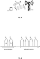
- Fig. 1 schematically illustrates an exemplary scenario in which a UE 10, e.g., a mobile phone, a tablet computer, or other kind of communication device, communicates with an access node 100 of the wireless communication network.
- the access node 100 may also be referred to as eNB ("evolved Node B").
- the communication between the UE 10 and the access node 100 is LAA based, i.e., uses carriers from both a licensed frequency spectrum and the unlicensed frequency spectrum.
- a DL (downlink) carrier 21 from the licensed frequency spectrum is used for DL radio transmissions from the access node 100 to the UE 10
- a UL carrier 22 from the licensed frequency spectrum is used for UL radio transmissions from the UE 10 to the access node 100.
- the carriers 21, 22 may also be referred to as PCell of the UE 10.
- DL carriers 31, 32 from the unlicensed frequency spectrum may be used for DL radio transmissions from the access node 100 to the UE 10
- UL carriers 33, 34 from the unlicensed frequency spectrum may be used for UL radio transmissions from the UE 10 to the access node 100.
- the same carrier e.g., the carrier 31, the carrier 32, the carrier 33, and/or the carrier 34
- the carrier 31 could also be used for both DL radio transmissions from the access node 100 to the UE 10 and UL radio transmissions from the UE 10 to the access node 100, e.g., by using the carrier in a TDD (Time Division Duplex) mode.
- the carriers 31, 32, 33, 34 may also be referred to as SCell(s) of the UE 10.
- Fig. 2 schematically illustrates the carriers 21, 22, 31, 32, 33, 34 in frequency (f) space.
- the carriers 21, 22 are in a licensed frequency spectrum, e.g., in one of the LTE bands between 700MHz and 2.7GHz.
- one or more DL control channels like a PDCCH (Physical DL Control Channel) or ePDDCH (enhanced PDDCH) may be transmitted on the DL carrier 21.
- PDCCH Physical DL Control Channel
- ePDDCH enhanced PDDCH
- one or more UL control channels may be transmitted on the UL carrier 22.
- the carriers may be used for transmission of a data channel.
- one or more DL data channels like a PDSCH (Physical DL Shared Channel) may be transmitted on the DL carrier 21.
- one or more UL data channels like a PUSCH (Physical UL Shared Channel) may be transmitted on the UL carrier 22.
- the PDSCH and the PUSCH are used in a shared manner by multiple UEs, and allocation of radio resources of the PDSCH or PUSCH to a certain UE, like the UE 10, is accomplished by the access node 100.
- the carriers 31, 32, 33, 34 which are shared with other operators or radio technologies, may be used for enhancing transmission capacity or transmission performance between the UE 10 and the access node 100.
- Control information for the carriers 31, 32, 33, 34 may be transmitted on the carriers 21, 22, i.e., transmissions on the carriers 31, 32, 33, 34 may be assisted by transmissions on the carriers 21, 22.
- the carriers 31, 32, 33, 34 may thus also be referred to as LAA SCell(s).
- one or more DL data channels like a PDSCH, may be transmitted on the DL carriers 31, 32 and/or one or more UL data channels, like a PUSCH, may be transmitted on the UL carriers 33, 34.
- the PDSCH and the PUSCH in the unlicensed frequency spectrum are used in a shared manner by multiple UEs, and allocation of radio resources of the PDSCH or PUSCH to a certain UE, like the UE 10, is accomplished by the access node 100.
- DL radio transmissions and UL radio transmissions could also be performed on the same carrier, e.g., one of the carriers 21, 22, 31, 32, 33, 34, using different time slots for the DL radio transmissions and UL radio transmissions, e.g., using a TDD mode.
- FDD Frequency Division Duplex
- usage of the carriers 21, 22 could be omitted, and also control channels, like a PDCCH, ePDCCH, MF-sPUCCH or MF-ePUCCH, could be transmitted on the carriers 31, 32, 33, 34 from the unlicensed frequency spectrum.
- control channels like a PDCCH, ePDCCH, MF-sPUCCH or MF-ePUCCH, could be transmitted on the carriers 31, 32, 33, 34 from the unlicensed frequency spectrum.
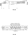
- Fig. 3A-3D illustrate the allocation of radio resources in the LTE radio technology.
- the LTE radio technology uses OFDM (Orthogonal Frequency Division Multiplexing).
- the underlying time-frequency grid is in the frequency (f) domain defined by multiple subcarriers of 15kHz width, and in the time (t) domain defined by a sequence of OFDM symbols forming a subframe of 1ms duration. Each OFDM symbol starts with a cyclic prefix.
- a similar time-frequency grid, using the same subcarrier spacing and number of modulation symbols is used for the UL radio transmissions.
- the LTE radio technology uses DFT (Discrete Fourier Transform) spread OFDM, also referred to as single-carrier FDMA (Frequency Division Multiple Access). Accordingly, the radio resources of the LTE radio technology can be regarded as being organized in a time-frequency grid defining resource elements each corresponding to one subcarrier during and one modulation symbol interval, e.g., as illustrated in Fig. 1 .
- DFT Discrete Fourier Transform
- single-carrier FDMA Frequency Division Multiple Access
- Fig. 3B further illustrates organization of the LTE radio transmissions in the time domain.
- the radio transmissions are organized in a sequence of radio frames, and each radio frame is formed of multiple subframes.
- Each subframe comprises two slots which each have a duration of 0.5ms. Within a radio frame, the slots are sequentially numbered within a range from 0 to 19. For normal cyclic prefix length, one subframe consists of 14 OFDM symbols, and the duration of each symbol is approximately 71.4 ⁇ s.
- the resource allocation in LTE radio technology is typically defined in terms of resource blocks, where a resource block corresponds to one slot (0.5ms) in the time domain and 12 contiguous subcarriers in the frequency domain.
- a pair of two adjacent resource blocks in time direction (1.0ms) is also referred to as a resource block pair.
- the resource blocks are indexed in the frequency domain, starting with index 0 from one end of the system bandwidth.
- the DL radio transmissions are typically subject to dynamic scheduling. That is to say, in each subframe the access node 100 transmits DL control information (DCI).
- the control information indicates to which UEs data is transmitted in this subframe, and in which resource blocks include the data for a specific UE.
- Fig. 3C shows an example of DL subframe.
- the DCI may be transmitted in the first OFDM symbols of the DL subframe, also referred to as control region of the DL subframe.
- the control region corresponds to the first 1, 2, 3 or 4 OFDM symbols of the DL subframe.
- the number n of the OFDM symbols defining the control region is also referred to as CFI (Control Format Indicator).
- the DL subframe also contains reference symbols, which are known to the receiver and used for demodulation purposes, e.g., for coherent demodulation of the control information.
- the reference symbols may also include cell specific reference symbols (CRS) which may be are used to support various functions, such as fine time and frequency synchronization and channel estimation for certain transmission modes.
- CRS cell specific reference symbols
- the UL radio transmissions are typically subject to dynamic scheduling.
- the access node 100 may indicate in the DCI information which UEs shall transmit UL data in a subsequent subframe, and in which resource blocks the UL data is to be transmitted by the UE(s).
- Fig. 3D shows an example of a UL subframe.
- the UL resource grid may include UL data and UL control information.
- the UL data and the UL control information may be included in a shared data channel, referred to as PUSCH (Physical UL Shared Channel).
- the UL control information may be included in a control channel, referred to as PUCCH (Physical UL Control Channel).
- a UL subframe may also include various reference signals, such as demodulation reference signals (DMRS) and sounding reference signals (SRS).
- DMRS demodulation reference signals
- SRS sounding reference signals
- DMRS are used for coherent demodulation of the PUSCH and PUCCH.
- the SRS are typically not associated with any data or control information and are used to estimate the UL channel quality, e.g., for purposes of frequency-selective scheduling. As illustrated in Fig.
- the DMRS and SRS are time-multiplexed into the UL subframe, and the SRS are transmitted in the last symbol of the UL subframe.
- the DMRS are typically transmitted once every slot for subframes with normal cyclic prefix, and may be located in the fourth and eleventh SC-FDMA symbols.
- the DCI may for example indicate the following information for controlling UL radio transmissions:
- the DCI is typically UE specific and CRC (Cyclic Redundancy Check) protected, typically using CRC bits.
- the UE specific character of the DCI is achieved by scrambling the CRC bits with a UE-specific identifier, e.g., a C-RNTI (Cell Radio Network Temporary Identifier). Further, the DCI and scrambled CRC bits typically protected by convolutional coding.
- the access node 100 assigns a unique C-RNTI to every UE associated to it.
- the C-RNTI can take values in the range 0001-FFF3 in hexadecimal format.
- the DCI may be transmitted in a DL control channel referred to as PDCCH (Physical DL Control Channel), which exclusively uses resource elements from the control region of the DL subframe.
- DL control information may also be transmitted in a DL control channel referred to as ePDCCH, which uses resource elements outside the control region.
- a specific type of DL control information which may be transmitted in the PDCCH or ePDCCH is scheduling information, such as a DL assignment, allocating DL radio resources for a DL radio transmission to the UE 10, or a UL grant, allocating UL radio resources for a UL radio transmission from the UE 10.
- the dynamic scheduling of UL radio transmissions may be accomplished in the following manner:
- the UE 10 reports to the access node 100 when it needs to transmit UL data, e.g., by sending a scheduling request (SR).
- SR scheduling request
- the access node 100 allocates the radio resources and sends corresponding scheduling information in an UL grant to the UE 10. If the allocated radio resources are not sufficient to transmit all the UL data, the UE 10 may further send a buffer status report (BSR) on the allocated radio resources, thereby informing the access node 100 about the amount of UL data still pending for transmission.
- BSR buffer status report
- the access node 100 may allocate further radio resources to the UE 10, so that the UE 10 can continue with the transmission of the UL data
- dynamic scheduling may be performed according to the following procedure:
- a delay of 16ms or more can occur between arrival of the UL data in the empty buffer and reception of this UL data by the access node 100. This delay can be further increased by the UE 10 having to wait for the next opportunity to the SR and/or by the UE 10 having to perform a random access procedure to obtain synchronization and being allocated with SR opportunities.
- UE 10 and the access node 100 may need to implement an LBT procedure or similar mechanism to avoid conflicts with other radio devices or radio technologies which may potentially use the carriers 31, 32, 33, 34.
- Fig. 4A illustrates an example of an LBT procedure which may be used to ensure coexistence with WLAN transmissions on the carrier 32.
- station A and station B transmit on the carrier 33 from the unlicensed frequency spectrum.
- station A finishes transmission of a data frame to station B.
- SIFS Short Inter Frame Space
- station B sends an ACK frame back to station A.
- the SIFS time may for example be 16 ⁇ s.
- the station B sends the ACK frame without performing a LBT operation.
- another radio device such as the UE 10 can transmit on the carrier 33, it first needs to sense the carrier 33 to determine whether it is occupied.
- a radio device such as the UE 10, that wishes to transmit first performs a CCA (Clear Channel Assessment) by sensing the carrier for the DIFS time. If the medium is idle then the radio device assumes that the carrier 33 is free and that it may transmit on the carrier 33. If the carrier 33 is found to be busy, the radio device waits until the carrier 33 goes idle, and defers for the DIFS time.
- CCA Common Channel Assessment
- the radio device may wait for a random backoff period before it can start to transmit on the carrier 33 at t4.
- the random backoff period has the purpose of reducing the risk of collisions when multiple radio devices are ready to transmit when the carrier 33 goes idle.
- the radio device starts a random backoff counter at t3 and defers for a corresponding number of time slots.
- the random backoff counter may be selected as a random integer of not more than a backoff contention window size CW.
- the backoff contention window size CW may be doubled whenever a collision is detected, up to a limit CWmax. When a transmission attempt is successful without collision the contention window is reset back to its initial value.
- Fig. 4B illustrates a further example of an LBT procedure which is based on Load-based CCA according to ETSI Draft EN 301 893 V2.1.0 (2017-03 ).
- a radio device not using a WLAN protocol such as the UE 10
- the radio device that initiates a sequence of one or more transmissions is denoted as the Initiating Device. Otherwise, the radio device is denoted as a Responding Device.
- the Initiating Device implements a channel access mechanism which is based on prioritized, truncated exponential backoff.
- the Initiating Device Before a transmission or a burst of transmissions on an Operating Channel, such as the carrier 33, the Initiating Device operates at least one Channel Access Engine (up to four access engines can be operated simultaneously, corresponding to different data priority classes) that executes a procedure described in step 1) to step 8) below.
- a single Observation Slot shall have a duration of not less than 9 ⁇ s.
- the Channel Access Engine shall adjust CW to ((CW + 1) ⁇ m) - 1 with m ⁇ 2. If the adjusted value of CW is greater than CWmax the Channel Access Engine may set CW equal to CWmax. The Channel Access Engine shall then proceed with step 2).
- the Responding Device may transmit either without performing a CCA, if these transmissions are initiated at most 16 ⁇ s after the last transmission by the Initiating Device that issued the grant, or it performs CCA on the Operating Channel during a single observation slot within a 25 ⁇ s period ending immediately before the granted transmission time.
- a UE such as the above-mentioned UE 10
- a UE is configured with more than one unlicensed carrier for UL transmissions, of which at least one, denoted by CC1, is configured to be used on the basis of an access scheme involving dynamic scheduling, and of which at least one other, denoted by CC2, is configured to be used on the basis of an access scheme involving grant-less transmission.
- the carriers CC1 and CC2 may for example correspond to the above-mentioned carriers 33 and 34.
- the utilization of different access schemes on the two carriers CC1, CC2 may for example be due to heterogeneous traffic and interference levels, or due to the clustering of UEs capable of grant-less UL radio transmissions on a carrier that is separate from one or more carriers utilized by legacy UEs which only support dynamically scheduled UL radio transmissions.
- successful CCA is required before the UE can start transmitting on the carrier CC1, CC2.
- the CCA may be part of an extended LBT procedure which involves a backoff before starting to transmit. Further, the CCA may be part of a shortened LBT procedure which requires no backoff before starting to transmit.
- an UL grant to schedule UL resources may refer to a single UE-specific DCI, or to a two-stage process with PUSCH trigger A sent using UE-specific DCI and PUSCH trigger B sent using a common or UE-specific DCI.
- a scheduled UL radio transmission i.e., an UL radio transmission performed on radio resources allocated by an UL grant, may for example include a PUSCH transmission and/or a transmission on short/long PUCCH.
- the UE may compute its PHR (Power Headroom Report) assuming that all potentially available carriers are used for parallel UL radio transmissions, irrespective whether CCA is successful on the individual carriers.
- PHR Power Headroom Report
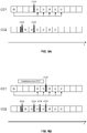
- a sequence of boxes for each carrier illustrates subframes which are potentially usable for UL radio transmissions.
- Subframes used for an UL radio transmission are marked with "U”.
- a subframe where the UE receives a UL grant allocating radio resources of the carrier to the UE is denoted by "G”.
- the UL grant may be received on a DL control channel, e.g., a PDCCH or ePDCCH. In some scenarios, such DL control channel could be transmitted on the same carrier, e.g., when using a TDD transmission mode.
- a subframe where the UE defers its transmission is denoted by "D".
- the subframes which include radio resources allocated by the UL grant are indicated by arrows extending from the subframe in which the UL grant is received.
- a subframe where the UE cannot transmit due to unsuccessful LBT is denoted by "X”.
- Successful CCA on the carrier is illustrated by a shaded box.
- the UE can start an UL transmission on the carrier CC2, which allows grant-less transmission, during any subframe after successful CCA.
- an UL radio transmission on the carrier CC1 which requires dynamic scheduling, is possible only on those subframes which include radio resources which were allocated by an UL grant to the UE.
- this has the effect that an ongoing UL radio transmission on the carrier CC2 partially overlaps with the subframes which include radio resources allocated by the UL grant on CC1.
- the radio resources allocated by the UL grant are in the subframes with index n+4, n+5, n+6, n+7, and n+8.
- the UE performs a successful CCA procedure on the carrier CC2 before the subframe with index n+2 and starts with the UL radio transmission on the carrier CC2.
- This UL radio transmission ends in the subframe with index n+6. Due to self-interference from the ongoing UL radio transmission on the carrier CC2, LBT on the carrier CC1 is unsuccessful in the subframes with index n+4, n+5, and n+6.
- the UE can successfully perform CCA and start the UL radio transmission on CC1 in the subframe with index n+8. As can be seen, the result is inefficient usage of the radio resources of the carrier CC1. In the examples as further detailed below, such problems can be avoided by coordination of the UL radio transmissions on the different unlicensed carriers.
- the scenario of Fig. 6 is similar to that of Fig. 5 , but involves coordination of UL radio transmissions on the carrier CC1 and UL radio transmissions on the carrier CC2.
- the UE performs successful CCA on the carrier CC2 before the subframe with index n+2.
- this CCA may be part of an extended LBT procedure, including a backoff after detecting that the carrier CC1 is unoccupied.
- the UE defers starting the UL radio transmission on the carrier CC2 until the first subframe including radio resources allocated by the UL grant on the carrier CC1, i.e., until the subframe with index n+4.
- the UE After successful CCA on both carriers before the subframe with index n+4, the UE starts with the UL radio transmissions on both carriers CC1, CC2.
- the CCA performed on the carriers before the subframe with index n+4 may be part of a shortened LBT procedure which requires no backoff after detecting that the carrier CC1 is unoccupied.
- using the shortened LBT procedure is acceptable because an extended LBT procedure with backoff was already performed before the subframe with index n+2.
- the UE Because during the CCA on one of the carriers the UE is not transmitting on the other carrier, the outcome of the CCA is not affected.
- the UE can therefore also transmit during the subframes with index n+4, n+5, n+6, and n+7 on the carrier CC1. Accordingly, the radio resources are utilized in an efficient manner.
- Fig. 7 illustrates a further example of a scenario which is similar to that of Fig. 5 and involves coordination of UL radio transmissions on the carrier CC1 and UL radio transmissions on the carrier CC2.
- the UE has data to transmit already in the subframe with index n+2.
- the UE defers its transmission until the first subframe including radio resources allocated by the UL grant on the carrier CC1, i.e., until the subframe with index n+4.
- the UE starts with the UL radio transmissions on both carriers CC1, CC2.
- the CCA performed on the carrier CC1 before the subframe with index n+4 may be part of an extended LBT procedure which includes a backoff after detecting that the carrier CC1 is unoccupied, while the CCA performed on the carrier CC2 before the subframe with index n+4 may be part of a shortened LBT procedure which requires no backoff after detecting that the carrier CC1 is unoccupied.
- using the shortened LBT procedure on the carrier CC2 is acceptable because an extended LBT procedure with backoff is performed on the carrier CC1.
- the UE can therefore also transmit during the subframes with index n+4, n+5, n+6, and n+7 on the carrier CC1. Accordingly, the radio resources are utilized in an efficient manner.
- Fig. 8 illustrates a further example of a scenario which is similar to that of Fig. 5 and involves coordination of UL radio transmissions on the carrier CC1 and UL radio transmissions on the carrier CC2.
- the UE has data to transmit already in the subframe with index n+2.
- the UE defers its transmission until after the last subframe including radio resources allocated by the UL grant on the carrier CC1.
- the UE starts with the UL radio transmissions on the carrier CC1.
- the UE After successful CCA on the carrier CC2 before the subframe with index n+10, the UE starts with the UL radio transmissions on the carrier CC2.
- the CCA performed on both carriers CC1, CC2 may be part of an extended LBT procedure which includes a backoff after detecting that the carrier is unoccupied.
- the CCA performed on the carrier CC2 before the subframe with index n+10 could also be part of a shortened LBT procedure which requires no backoff after detecting that the carrier CC1 is unoccupied. Because during the CCA on one of the carriers the UE is not transmitting on the other carrier, the outcome of the CCA is not affected. As compared to the scenario of Fig. 5 , the UE can therefore also transmit during the subframes with index n+4, n+5, n+6, and n+7 on the carrier CC1. Accordingly, the radio resources are utilized in an efficient manner.
- Figs. 9A and 9B illustrate a further example of a scenario which is similar to that of Fig. 5 and involves coordination of UL radio transmissions on the carrier CC1 and UL radio transmissions on the carrier CC2.
- the UE performs a successful CCA procedure on the carrier CC2 before the subframe with index n+2 and starts with the UL radio transmission on the carrier CC2.
- the CCA performed on the carrier CC1 before the subframe with index n+2 may be part of an extended LBT procedure which includes a backoff after detecting that the carrier is unoccupied.
- the UE interrupts the ongoing UL radio transmission on the carrier CC2. Accordingly, a gap for CCA on the carrier CC1 is introduced into the UL radio transmission on the carrier CC2. As illustrated, in this gap the UE may also perform CCA on the carrier CC2, thereby ensuring that both carriers are unoccupied.
- the detailed timing of the gap i.e., start time, end time, and duration may depend on the type of LBT procedure used on the carriers CC1 and CC2. Further, the end time of the gap may depend on a start position of a data channel, e.g., PUSCH, within the next subframe.
- the gap may be configured to end at or before the start of the subframe. If the data channel starts with a later modulation symbol of the subframe, the gap may be configured to end within the next subframe, before the start of the data channel within the subframe.
- the UE After successful CCA on the carriers CC1, CC2 before the subframe with index n+4, the UE starts with the UL radio transmission on the carrier CC1 and continues with the UL radio transmission on the carrier CC2.
- the CCA performed on both carriers CC1, CC2 before the subframe with index n+4 may be part of a shortened LBT procedure which requires no backoff after detecting that the carrier CC1, CC2 is unoccupied.
- using the shortened LBT procedure is acceptable because an extended LBT procedure with backoff was already performed before the subframe with index n+2.
- the UE can therefore also transmit during the subframes with index n+4, n+5, n+6, and n+7 on the carrier CC1. Further, also utilization of the subframes with index n+2 and n+3 is possible on the carrier CC2. The latter further enhances efficiency of radio resource utilization. In addition, it can be avoided that some other radio device occupies the carrier CC1 and/or CC2 while the UE is deferring its transmission.
- multiple gaps may be introduced in the ongoing UL radio transmission on the carrier CC2.
- FIG. 9B An example of a corresponding scenario is illustrated in Fig. 9B .
- the UE performs a successful CCA procedure on the carrier CC2 before the subframe with index n+2 and starts with the UL radio transmission on the carrier CC2.
- the CCA performed on the carrier CC1 before the subframe with index n+2 may be part of an extended LBT procedure which includes a backoff after detecting that the carrier is unoccupied.
- the UE interrupts the ongoing UL radio transmission on the carrier CC2.
- a gap for CCA on the carrier CC1 is introduced into the UL radio transmission on the carrier CC2.
- the UE may also perform CCA on the carrier CC2, to ensure that both carriers are unoccupied.
- the detailed timing of the gap i.e., start time, end time, and duration may depend on the type of LBT procedure used on the carriers CC1 and CC2 and/or on a start position of a data channel, e.g., PUSCH, within the next subframe.
- the scenario of Fig. 9B assumes that during the subframes with index n+1 to n+5 there is interference to the carrier CC1, e.g., from some other radio device transmitting on the carrier CC1 or on a frequency which is close to the carrier CC1. This interference however does not affect the carrier CC2. Accordingly, before the subframe with index n+4 CCA on the carrier CC1 is unsuccessful, and in the subframe with index n+4 the UE cannot start transmitting on the carrier CC1. On the carrier CC2 CCA is successful before the subframe with index n+4, and the UE thus continues with the UL radio transmission on the carrier CC2.
- a further gap for CCA on the carrier CC1 is introduced into the UL radio transmission on the carrier CC2. Again, this gap may also be used by the UE to perform CCA on the carrier CC2.
- the detailed timing of the gap i.e., start time, end time, and duration may depend on the type of LBT procedure used on the carriers CC1 and CC2 and/or on a start position of a data channel, e.g., PUSCH, within the next subframe.
- the position or duration of the gap could vary as compared to the gap introduced before the subframe with index n+4. Since in the illustrated example the interference to the carrier CC1 still exists at the beginning of the subframe with index n+4, the CCA on the carrier CC1 is unsuccessful also before the subframe with index n+5, and also in the subframe with index n+5 the UE cannot start transmitting on the carrier CC1. On the carrier CC2 CCA is successful also before the subframe with index n+5, and the UE thus continues with the UL radio transmission on the carrier CC2.
- the UE Since the UE still could not start its transmission on the carrier CC1, it again interrupts the ongoing UL radio transmission on the carrier CC2 before the next subframe including radio resources allocated by the UL grant received on the carrier CC1, in the illustrated example the subframe with index n+6, and a still further gap for CCA on the carrier CC1 is introduced into the UL radio transmission on the carrier CC2. Again, this gap may also be used by the UE to perform CCA on the carrier CC2. Again, the detailed timing of the gap, i.e., start time, end time, and duration may depend on the type of LBT procedure used on the carriers CC1 and CC2 and/or on a start position of a data channel, e.g., PUSCH, within the next subframe.
- a data channel e.g., PUSCH
- the CCA performed during the gaps in the UL radio transmission on CC2 may be part of a shortened LBT procedure which requires no backoff after detecting that the carrier CC1, CC2 is unoccupied.
- using the shortened LBT procedure is acceptable because an extended LBT procedure with backoffwas already performed before the subframe with index n+2. It is noted that in some scenarios it could also happen that interference arises on the carrier CC2, resulting in an unsuccessful CCA on the carrier CC2. In such case, the UE would not continue with its UL radio transmission on the carrier CC2.
- interference may be taken into account in an efficient manner by ending or interrupting an ongoing UL radio transmission on one of the carriers CC1, CC2, so that CCA on the other carrier is not affected.
- Figs. 10A and 10B illustrate a further example of a scenario which is similar to that of Fig. 5 and involves coordination of UL radio transmissions on the carrier CC1 and UL radio transmissions on the carrier CC2.
- Fig. 10A illustrates that subframes in which the UE receives UL grants may be interweaved with the subframes used for UL radio transmissions, with the aim of leaving as few as possible subframes unused. This may be achieved by a variable time offset between transmission of the UL grant and the first subframe including radio resources allocated by the UL grant.
- no subframes are left unused on the carrier CC1.
- the UE does not transmit on the carrier CC2.
- Fig. 10B illustrates an example of a scenario in which such problems are addressed by coordination of the UL radio transmissions on the carrier CC1 and the UL radio transmissions on the carrier CC2. In the scenario of Fig.
- the UE aligns the UL radio transmissions on the carrier CC2 with the subframes including radio resources allocated by the UL grants received on the carrier CC1.
- the result is that, when an UL radio transmission on the carrier CC1 ends, an UL radio transmission on the carrier CC2 would end as well, so that the UE can then receive the next UL grant on the carrier CC1.
- This may for example be achieved by configuring the UE to check whether the next subframe on the carrier CC1 includes radio resources allocated by an UL grant and, if this is not the case, terminating an ongoing UL radio transmission on the carrier CC2 before the next subframe even though the UE might still have data to transmit on the carrier CC2.
- the UE may then receive an UL grant, as illustrated in Fig. 10B .
- the next subframe could also be used by the UE to receive other control information and/or DMRS on the carrier CC1.
- Figs. 10A and 10B do not illustrate LBT procedures or CCA required to perform the illustrated UL radio transmissions. However, it is to be understood that LBT and CCA on the different carriers may be coordinated as explained in connection with Figs. 6 , 7 , 8 , 9A, and 9B .
- Fig. 11 shows a flowchart for illustrating a method of controlling radio transmissions.
- the method of Fig. 11 may be utilized for implementing the illustrated concepts in a radio device, such as the above-mentioned UE 10. If a processor-based implementation of the radio device is used, the steps of the method may be performed by one or more processors of the radio device. In such a case the radio device may further comprise a memory in which program code for implementing the below described functionalities is stored.
- the radio device controlling a first UL radio transmission on a first carrier from an unlicensed frequency spectrum.
- the first UL radio transmission is controlled on the basis of a first access scheme.
- the radio device controls a second UL radio transmission on a second second carrier from the unlicensed frequency spectrum.
- the first UL radio transmission is controlled on the basis of a second access scheme which is different from the first access scheme.
- the first access scheme may involve that radio resources of the first carrier are allocated to the radio device by a first type of grant received from the wireless communication network, while the second access scheme involves that radio resources of the second carrier are allocated to the radio device by a second type of grant which has a longer validity than the first type of grant.
- the first type of grant could be a dynamic scheduling grant sent in response to a scheduling request from the radio device
- the second type of grant could be an SPS grant or an IUA grant, which is sent without scheduling request from the radio device.
- the first type for grant may be valid for a limited number of subframes, while the second type of grant is valid in a reoccurring manner in a sequence of subframes, until the grant is released.
- the first access scheme may involve that radio resources of the first carrier are allocated to the radio device in response to a request from the radio device, while the second access scheme involves that radio resources of the second carrier are allocated to the radio device without request from the radio device.
- the radio resources of the first carrier could be allocated by a dynamic scheduling grant, which is sent in response to a scheduling request from the radio device, and the radio resources of the second carrier are allocated by an SPS grant or an IUA grant, which is sent without scheduling request from the radio device.
- the first access scheme may involve that radio resources radio resources of the first carrier are allocated to the radio device by a grant from the wireless communication network, while the second access scheme does not require allocation of radio resources to the radio device by a grant from the wireless communication network.
- the radio resources of the first carrier could be allocated by a dynamic scheduling grant, which is sent in response to a scheduling request from the radio device or by an IUA grant or SPS grant, and the radio resources of the second carrier could be accessible without requiring resource allocation by the wireless communication network, e.g., through grant-less access.
- the radio device coordinates the first UL radio transmission and the second UL radio transmission.
- the radio device may receive a grant allocating radio resources of the first carrier to the radio device and, before starting to perform the first UL radio transmission on the allocated radio resources, performing channel sensing on the first carrier. Examples of such channel sensing are the CCA operations performed in the examples of Figs. 6 , 7 , 8 , 9A, and 9B before the UE start with the UL transmission on the carrier CC1.
- the channel sensing may be part of an LBT procedure.
- the LBT procedure may correspond to an extended LBT procedure which requires initiating a backoff period when detecting that the carrier is unoccupied, and starting to transmit only after expiry of the backoff period, e.g., as explained in connection with Figs. 4A and 4B .
- the LBT procedure may also correspond to a shortened LBT procedure which does not require initiating a backoff period when detecting that the carrier is unoccupied, and allows starting to transmit immediately after detecting that the carrier is unoccupied.
- the coordination of step 1130 may then involve that the radio device may then perform the second UL radio transmission in at least one time window which is non-overlapping with the channel sensing on the first carrier.
- the examples of Figs. 6 , 7 , 8 , 9A, and 9B show a corresponding coordinated timing of the UL radio transmission on the carrier CC2.
- the at least one time window may include a time window starting after the channel sensing on the first carrier.
- the examples of Figs. 6 , 7 , 8 , 9A, and 9B show a corresponding coordinated timing of the UL radio transmission on the carrier CC2.
- such time window starts after the CCA before the subframe with index n+4.
- such time window starts in the subframe with index n+10.ln the example of Fig.
- the UL radio transmission includes a time window starting after the CCA before the subframe with index n+4, a time window starting after the CCA before the subframe with index n+ 5, and a time window starting after the CCA before the subframe with index n+ 6.
- the at least one time window may include a time window starting after the first radio transmission.
- the example of Fig. 8 shows a corresponding coordinated timing of the UL radio transmission on the carrier CC2.
- the time window starts in the subframe with index n+10, after the UE finished the UL radio transmission on the carrier CC1.
- the at least one time window may include a time window ending before the channel sensing on the first carrier.
- the examples of Figs. 9A and 9B show a corresponding coordinated timing of the UL radio transmission on the carrier CC2.
- the UL radio transmission on the carrier CC2 includes a time window ending before the CCA before the subframe with index n+4.
- Fig. 8 shows a corresponding coordinated timing of the UL radio transmission on the carrier CC2.
- the time window starts in the subframe with index n+10, after the UE finished the UL radio transmission on the carrier CC1.
- the at least one time window may include a time window ending before the channel sensing on the first carrier.
- the UL radio transmission on the carrier CC2 includes a time window ending before the CCA before the subframe with index n+4, two time windows ending before the CCA before the subframe with index n+5, and three time windows ending before the CCA before the subframe with index n+5.
- the at least one time window includes a first time window ending before the channel sensing on the first carrier and a second time window starting after the channel sensing on the first carrier.
- the examples of Figs. 9A and 9B show a corresponding coordinated timing of the UL radio transmission on the carrier CC2.
- a gap is included between the first time window and the second time window, and this gap may be used for the channel sensing on the first carrier.
- the radio device may perform channel sensing on the second carrier before starting to perform the second uplink radio transmission.
- Examples of such channel sensing are the CCA operations performed in the examples of Figs. 6 , 7 , 8 , 9A, and 9B before the UE start with the UL transmission on the carrier CC1.
- the channel sensing may be part of an LBT procedure.
- the LBT procedure may correspond to an extended LBT procedure which requires initiating a backoff period when detecting that the carrier is unoccupied, and starting to transmit only after expiry of the backoff period, e.g., as explained in connection with Figs. 4A and 4B .
- the LBT procedure may also correspond to a shortened LBT procedure which does not require initiating a backoff period when detecting that the carrier is unoccupied, and allows starting to transmit immediately after detecting that the carrier is unoccupied.
- the at least one time window may include a time window between the channel sensing on the second carrier and the channel sensing on the first carrier.
- the examples of Figs. 9A and 9B show a corresponding coordinated timing of the UL radio transmission on the carrier CC2.
- the UL radio transmission on the carrier CC2 includes a time window between the CCA on the carrier CC2 before the subframe with index n+2 and the CCA on the carrier CC1 before the subframe with index n+4.
- Fig. 9A the UL radio transmission on the carrier CC2 includes a time window between the CCA on the carrier CC2 before the subframe with index n+2 and the CCA on the carrier CC1 before the subframe with index n+4.
- the UL radio transmission on the carrier CC2 includes a time window between the CCA on the carrier CC2 before the subframe with index n+2 and the unsuccessful CCA on the carrier CC1 before the subframe with index n+4, a time window between the CCA on the carrier CC2 before the subframe with index n+2 and the unsuccessful CCA on the carrier CC1 before the subframe with index n+5, and a time window between the CCA on the carrier CC2 before the subframe with index n+2 and the successful CCA on the carrier CC1 before the subframe with index n+6.
- the coordination may involve that during the channel sensing on the first carrier, the radio device also performs channel sensing on the second carrier.
- the examples of Fig. 6 , 7 , 9A, and 9B show a corresponding coordination of channel sensing.
- the radio resources allocated by the received grant define an end time of the first UL radio transmission.
- the coordination may then involve that the radio device ends the second UL radio transmission at the end time of the first uplink radio transmission.
- a corresponding example is shown in Fig. 10B .
- the radio device may then receive a further grant allocating radio resources of the first carrier to the radio device.
- the radio device could also receive other control information or reference signals.
- the coordination may also involve controlling the usage of a backoff during LBT on the first carrier or second carrier.
- the radio device may perform channel sensing on the first carrier and, in response to detecting that the first carrier is unoccupied, initiate a backoff period. Accordingly, the radio device may perform an extended LBT procedure on the first carrier. Upon expiry of the backoff period, the radio device may then performing further channel sensing on the first carrier and start the first UL radio transmission in response to the further channel sensing on the first carrier indicating that the first carrier is unoccupied. Further, upon expiry of the backoff period, the radio device may also performing channel sensing on the second carrier and start the second UL radio transmission in response to the channel sensing on the second carrier indicating that the second carrier is unoccupied.
- the second UL radio transmission may be started immediately after detecting that the second carrier is unoccupied, without initiating a backoff period. That is to say, a shortened LBT procedure on one of the first and second carriers may be coordinated with an extended LBT procedure on the other of the first and second carriers.
- Fig. 6 , 7 , 9A, and 9B show a corresponding coordination of channel sensing.
- Fig. 12 shows a block diagram for illustrating functionalities of a radio device 1200 which operates according to the method of Fig. 11 .
- the radio device 1200 may be provided with a module 1210 configured to control a first UL radio transmission on a first carrier from an unlicensed frequency spectrum on the basis of a first access scheme, such as explained in connection with step 1110.
- the radio device 1200 may be provided with a module 1220 configured to control a second UL radio transmission on a second carrier from the unlicensed frequency spectrum on the basis of a second access scheme which is different from the first access scheme, such as explained in connection with step 1120.
- radio device 1200 may be provided with a module 1230 configured to coordinate the first UL radio transmission and the second radio transmission, such as explained in connection with step 1130.
- the radio device 1200 may include further modules for implementing other functionalities, such as known functionalities of a UE supporting the LTE radio technology. Further, it is noted that the modules of the radio device 1200 do not necessarily represent a hardware structure of the radio device 1200, but may also correspond to functional elements, e.g., implemented by hardware, software, or a combination thereof.
- the illustrated concepts could also be implemented in a system which includes a radio device configured to operate according to the method of Fig. 11 and an access node which is configured to receive the first UL radio transmission and the second UL radio transmission, such as the above-mentioned access node 100.
- Fig. 13 illustrates a processor-based implementation of a radio device 1300 which may be used for implementing the above described concepts.
- the structures as illustrated in Fig. 13 may be used for implementing the above-mentioned UE 10.
- the radio device 1300 may include a radio interface 1310 for communicating with a wireless communication network, e.g., with an access node of the wireless communication network, such as the above-mentioned access node 100.
- the radio interface 1310 may be used for sending the above-mentioned UL radio transmissions. Further, the radio interface 1310 may be used for receiving control information, such as the above-mentioned grants or similar resource allocation information.
- the radio interface 1310 may for example be based on the LTE radio technology.
- the radio device 1300 may include one or more processors 1350 coupled to the radio interface 1310 and a memory 1360 coupled to the processor(s) 1350.
- the radio interface 1310, the processor(s) 1350, and the memory 1360 could be coupled by one or more internal bus systems of the radio device 1300.
- the memory 1360 may include a Read-Only-Memory (ROM), e.g., a flash ROM, a Random Access Memory (RAM), e.g., a Dynamic RAM (DRAM) or Static RAM (SRAM), a mass storage, e.g., a hard disk or solid state disk, or the like.
- the memory 1360 may include software 1370, firmware 1380, and/or control parameters 1390.
- the memory 1360 may include suitably configured program code to be executed by the processor(s) 1350 so as to implement the above-described functionalities of a radio device, such as explained in connection with Fig. 11 .
- the structures as illustrated in Fig. 13 are merely schematic and that the radio device 1300 may actually include further components which, for the sake of clarity, have not been illustrated, e.g., further interfaces or processors.
- the memory 1360 may include further program code for implementing known functionalities of a radio device, e.g., known functionalities of a UE.
- a computer program may be provided for implementing functionalities of the radio device 1300, e.g., in the form of a physical medium storing the program code and/or other data to be stored in the memory 1360 or by making the program code available for download or by streaming.
- the concepts as described above may be used for efficiently controlling UL radio transmissions in an unlicensed frequency spectrum.
- the concepts may be used to avoid that dynamically scheduled UL radio transmissions on an unlicensed carrier are affected by UL radio transmissions on other carriers which utilize a different access scheme, e.g., based on semi-persistent grants, based on IUA allocation, or based on grant-less access.
- a different access scheme e.g., based on semi-persistent grants, based on IUA allocation, or based on grant-less access.
- one or more carriers which were found to be occupied when starting a transmission on one of the carriers may be later joined into the transmission, e.g., by using carrier aggregation. In this way UL performance can be enhanced.
- the concepts can be implemented without requiring excessive changes in existing hardware or software of radio devices or network nodes.
- the illustrated concepts may be applied in connection with various kinds of wireless communication technologies, without limitation to the above-mentioned examples of LTE, LTE LAA, or MuLTEfire.
- the concepts could also be applied to a 5G (5 th Generation) radio technology, such as the NR (new Radio) technology developed by 3GPP.
- the illustrated concepts may be applied with respect to various numbers carriers from the unlicensed frequency spectrum, e.g., three or more carriers, and/or with respect to various numbers of different access schemes, e.g., three or more different access schemes.
- the illustrated concepts may be applied in various kinds of radio devices, including mobile phones, portable computing devices, machine type communication devices, and relay stations. Moreover, it is to be understood that the above concepts may be implemented by using correspondingly designed software to be executed by one or more processors of an existing device, or by using dedicated device hardware. Further, it should be noted that the illustrated nodes or devices may each be implemented as a single device or as a system of multiple interacting devices.
Landscapes
- Engineering & Computer Science (AREA)
- Signal Processing (AREA)
- Computer Networks & Wireless Communication (AREA)
- Physics & Mathematics (AREA)
- Health & Medical Sciences (AREA)
- General Health & Medical Sciences (AREA)
- Spectroscopy & Molecular Physics (AREA)
- Mobile Radio Communication Systems (AREA)
Applications Claiming Priority (2)
| Application Number | Priority Date | Filing Date | Title |
|---|---|---|---|
| US201762486492P | 2017-04-18 | 2017-04-18 | |
| PCT/EP2018/053715 WO2018192699A1 (en) | 2017-04-18 | 2018-02-14 | Coordination of uplink radio transmissions on unlicensed carriers |
Publications (2)
| Publication Number | Publication Date |
|---|---|
| EP3613232A1 EP3613232A1 (en) | 2020-02-26 |
| EP3613232B1 true EP3613232B1 (en) | 2021-10-13 |
Family
ID=61244591
Family Applications (1)
| Application Number | Title | Priority Date | Filing Date |
|---|---|---|---|
| EP18705889.6A Active EP3613232B1 (en) | 2017-04-18 | 2018-02-14 | Coordination of uplink radio transmissions on unlicensed carriers |
Country Status (6)
| Country | Link |
|---|---|
| US (1) | US11228917B2 (ja) |
| EP (1) | EP3613232B1 (ja) |
| JP (1) | JP6990714B2 (ja) |
| BR (1) | BR112019021773A2 (ja) |
| WO (1) | WO2018192699A1 (ja) |
| ZA (1) | ZA201906673B (ja) |
Families Citing this family (7)
| Publication number | Priority date | Publication date | Assignee | Title |
|---|---|---|---|---|
| US11564249B2 (en) * | 2018-05-10 | 2023-01-24 | Apple Inc. | Configured grant uplink (UL) transmission in new radio unlicensed (NR-U) |
| US11889322B2 (en) | 2019-03-12 | 2024-01-30 | Google Llc | User-equipment coordination set beam sweeping |
| EP3734885A1 (en) * | 2019-05-02 | 2020-11-04 | Panasonic Intellectual Property Corporation of America | User equipment and network node involved in communication |
| US10893572B2 (en) | 2019-05-22 | 2021-01-12 | Google Llc | User-equipment-coordination set for disengaged mode |
| WO2021015774A1 (en) | 2019-07-25 | 2021-01-28 | Google Llc | User-equipment-coordination-set regrouping |
| EP3797489A1 (en) | 2019-08-13 | 2021-03-31 | Google LLC | User-equipment-coordination-set control aggregation |
| WO2021054964A1 (en) | 2019-09-19 | 2021-03-25 | Google Llc | User-equipment-coordination-set selective participation |
Family Cites Families (6)
| Publication number | Priority date | Publication date | Assignee | Title |
|---|---|---|---|---|
| US20130208587A1 (en) | 2012-01-26 | 2013-08-15 | Interdigital Patent Holdings, Inc. | Dynamic parameter adjustment for lte coexistence |
| US9860776B2 (en) * | 2014-06-20 | 2018-01-02 | Qualcomm Incorporated | Method and apparatus for reducing self-jamming of transmissions on adjacent carriers |
| CN107211463B (zh) * | 2015-04-08 | 2021-02-12 | 诺基亚技术有限公司 | Enb控制的基于ue的有条件的载波选择 |
| EP3352522B1 (en) | 2015-09-17 | 2023-11-01 | LG Electronics Inc. | Method and device for performing lbt process on multiple carriers in wireless access system supporting unlicensed band |
| WO2018027815A1 (zh) * | 2016-08-11 | 2018-02-15 | 华为技术有限公司 | 基于非授权频谱的无线通信方法、基站和终端设备 |
| US10342038B2 (en) * | 2016-10-04 | 2019-07-02 | Qualcomm Incorporated | Method and apparatus for scheduling multiple uplink grants of different types |
-
2018
- 2018-02-14 JP JP2019556262A patent/JP6990714B2/ja active Active
- 2018-02-14 EP EP18705889.6A patent/EP3613232B1/en active Active
- 2018-02-14 BR BR112019021773A patent/BR112019021773A2/pt not_active IP Right Cessation
- 2018-02-14 WO PCT/EP2018/053715 patent/WO2018192699A1/en unknown
- 2018-02-14 US US16/604,631 patent/US11228917B2/en active Active
-
2019
- 2019-10-09 ZA ZA2019/06673A patent/ZA201906673B/en unknown
Also Published As
| Publication number | Publication date |
|---|---|
| US11228917B2 (en) | 2022-01-18 |
| JP2020517196A (ja) | 2020-06-11 |
| US20200351667A1 (en) | 2020-11-05 |
| ZA201906673B (en) | 2022-03-30 |
| WO2018192699A1 (en) | 2018-10-25 |
| BR112019021773A2 (pt) | 2020-05-05 |
| JP6990714B2 (ja) | 2022-01-12 |
| EP3613232A1 (en) | 2020-02-26 |
Similar Documents
| Publication | Publication Date | Title |
|---|---|---|
| US11589377B2 (en) | Control of uplink radio transmissions on semi-persistently allocated resources | |
| CN109863708B (zh) | 针对未调度的上行链路的harq反馈的方法和装置 | |
| EP3613232B1 (en) | Coordination of uplink radio transmissions on unlicensed carriers | |
| EP3417666B1 (en) | A method for determining parameters for transmitting on an uplink control channel | |
| EP3222103B1 (en) | Channel access in listen before talk systems | |
| US11844109B2 (en) | Controlling AUL transmissions when coexisting with scheduled UEs | |
| WO2017184071A9 (en) | Methods and apparatuses for performing unscheduled uplink transmissions on an unlicensed band | |
| EP3412105B1 (en) | Listen before talk for uplink transmission | |
| WO2017144665A1 (en) | Scheduling an uplink transmission over an unlicensed radio resource |
Legal Events
| Date | Code | Title | Description |
|---|---|---|---|
| STAA | Information on the status of an ep patent application or granted ep patent |
Free format text: STATUS: UNKNOWN |
|
| STAA | Information on the status of an ep patent application or granted ep patent |
Free format text: STATUS: THE INTERNATIONAL PUBLICATION HAS BEEN MADE |
|
| PUAI | Public reference made under article 153(3) epc to a published international application that has entered the european phase |
Free format text: ORIGINAL CODE: 0009012 |
|
| STAA | Information on the status of an ep patent application or granted ep patent |
Free format text: STATUS: REQUEST FOR EXAMINATION WAS MADE |
|
| 17P | Request for examination filed |
Effective date: 20190920 |
|
| AK | Designated contracting states |
Kind code of ref document: A1 Designated state(s): AL AT BE BG CH CY CZ DE DK EE ES FI FR GB GR HR HU IE IS IT LI LT LU LV MC MK MT NL NO PL PT RO RS SE SI SK SM TR |
|
| AX | Request for extension of the european patent |
Extension state: BA ME |
|
| DAV | Request for validation of the european patent (deleted) | ||
| DAX | Request for extension of the european patent (deleted) | ||
| GRAP | Despatch of communication of intention to grant a patent |
Free format text: ORIGINAL CODE: EPIDOSNIGR1 |
|
| STAA | Information on the status of an ep patent application or granted ep patent |
Free format text: STATUS: GRANT OF PATENT IS INTENDED |
|
| RIC1 | Information provided on ipc code assigned before grant |
Ipc: H04W 16/14 20090101AFI20210616BHEP Ipc: H04L 5/00 20060101ALI20210616BHEP Ipc: H04W 74/02 20090101ALN20210616BHEP Ipc: H04W 74/04 20090101ALN20210616BHEP Ipc: H04W 74/08 20090101ALN20210616BHEP Ipc: H04W 76/15 20180101ALN20210616BHEP |
|
| INTG | Intention to grant announced |
Effective date: 20210708 |
|
| GRAS | Grant fee paid |
Free format text: ORIGINAL CODE: EPIDOSNIGR3 |
|
| GRAA | (expected) grant |
Free format text: ORIGINAL CODE: 0009210 |
|
| STAA | Information on the status of an ep patent application or granted ep patent |
Free format text: STATUS: THE PATENT HAS BEEN GRANTED |
|
| AK | Designated contracting states |
Kind code of ref document: B1 Designated state(s): AL AT BE BG CH CY CZ DE DK EE ES FI FR GB GR HR HU IE IS IT LI LT LU LV MC MK MT NL NO PL PT RO RS SE SI SK SM TR |
|
| REG | Reference to a national code |
Ref country code: GB Ref legal event code: FG4D |
|
| REG | Reference to a national code |
Ref country code: CH Ref legal event code: EP |
|
| REG | Reference to a national code |
Ref country code: DE Ref legal event code: R096 Ref document number: 602018024948 Country of ref document: DE |
|
| REG | Reference to a national code |
Ref country code: IE Ref legal event code: FG4D |
|
| REG | Reference to a national code |
Ref country code: AT Ref legal event code: REF Ref document number: 1439059 Country of ref document: AT Kind code of ref document: T Effective date: 20211115 |
|
| REG | Reference to a national code |
Ref country code: NL Ref legal event code: FP |
|
| REG | Reference to a national code |
Ref country code: LT Ref legal event code: MG9D |
|
| REG | Reference to a national code |
Ref country code: AT Ref legal event code: MK05 Ref document number: 1439059 Country of ref document: AT Kind code of ref document: T Effective date: 20211013 |
|
| PG25 | Lapsed in a contracting state [announced via postgrant information from national office to epo] |
Ref country code: RS Free format text: LAPSE BECAUSE OF FAILURE TO SUBMIT A TRANSLATION OF THE DESCRIPTION OR TO PAY THE FEE WITHIN THE PRESCRIBED TIME-LIMIT Effective date: 20211013 Ref country code: LT Free format text: LAPSE BECAUSE OF FAILURE TO SUBMIT A TRANSLATION OF THE DESCRIPTION OR TO PAY THE FEE WITHIN THE PRESCRIBED TIME-LIMIT Effective date: 20211013 Ref country code: FI Free format text: LAPSE BECAUSE OF FAILURE TO SUBMIT A TRANSLATION OF THE DESCRIPTION OR TO PAY THE FEE WITHIN THE PRESCRIBED TIME-LIMIT Effective date: 20211013 Ref country code: BG Free format text: LAPSE BECAUSE OF FAILURE TO SUBMIT A TRANSLATION OF THE DESCRIPTION OR TO PAY THE FEE WITHIN THE PRESCRIBED TIME-LIMIT Effective date: 20220113 Ref country code: AT Free format text: LAPSE BECAUSE OF FAILURE TO SUBMIT A TRANSLATION OF THE DESCRIPTION OR TO PAY THE FEE WITHIN THE PRESCRIBED TIME-LIMIT Effective date: 20211013 |
|
| PGFP | Annual fee paid to national office [announced via postgrant information from national office to epo] |
Ref country code: GB Payment date: 20220225 Year of fee payment: 5 Ref country code: DE Payment date: 20220225 Year of fee payment: 5 |
|
| PG25 | Lapsed in a contracting state [announced via postgrant information from national office to epo] |
Ref country code: IS Free format text: LAPSE BECAUSE OF FAILURE TO SUBMIT A TRANSLATION OF THE DESCRIPTION OR TO PAY THE FEE WITHIN THE PRESCRIBED TIME-LIMIT Effective date: 20220213 Ref country code: SE Free format text: LAPSE BECAUSE OF FAILURE TO SUBMIT A TRANSLATION OF THE DESCRIPTION OR TO PAY THE FEE WITHIN THE PRESCRIBED TIME-LIMIT Effective date: 20211013 Ref country code: PT Free format text: LAPSE BECAUSE OF FAILURE TO SUBMIT A TRANSLATION OF THE DESCRIPTION OR TO PAY THE FEE WITHIN THE PRESCRIBED TIME-LIMIT Effective date: 20220214 Ref country code: PL Free format text: LAPSE BECAUSE OF FAILURE TO SUBMIT A TRANSLATION OF THE DESCRIPTION OR TO PAY THE FEE WITHIN THE PRESCRIBED TIME-LIMIT Effective date: 20211013 Ref country code: NO Free format text: LAPSE BECAUSE OF FAILURE TO SUBMIT A TRANSLATION OF THE DESCRIPTION OR TO PAY THE FEE WITHIN THE PRESCRIBED TIME-LIMIT Effective date: 20220113 Ref country code: LV Free format text: LAPSE BECAUSE OF FAILURE TO SUBMIT A TRANSLATION OF THE DESCRIPTION OR TO PAY THE FEE WITHIN THE PRESCRIBED TIME-LIMIT Effective date: 20211013 Ref country code: HR Free format text: LAPSE BECAUSE OF FAILURE TO SUBMIT A TRANSLATION OF THE DESCRIPTION OR TO PAY THE FEE WITHIN THE PRESCRIBED TIME-LIMIT Effective date: 20211013 Ref country code: GR Free format text: LAPSE BECAUSE OF FAILURE TO SUBMIT A TRANSLATION OF THE DESCRIPTION OR TO PAY THE FEE WITHIN THE PRESCRIBED TIME-LIMIT Effective date: 20220114 Ref country code: ES Free format text: LAPSE BECAUSE OF FAILURE TO SUBMIT A TRANSLATION OF THE DESCRIPTION OR TO PAY THE FEE WITHIN THE PRESCRIBED TIME-LIMIT Effective date: 20211013 |
|
| PGFP | Annual fee paid to national office [announced via postgrant information from national office to epo] |
Ref country code: NL Payment date: 20220224 Year of fee payment: 5 |
|
| REG | Reference to a national code |
Ref country code: DE Ref legal event code: R097 Ref document number: 602018024948 Country of ref document: DE |
|
| PG25 | Lapsed in a contracting state [announced via postgrant information from national office to epo] |
Ref country code: SM Free format text: LAPSE BECAUSE OF FAILURE TO SUBMIT A TRANSLATION OF THE DESCRIPTION OR TO PAY THE FEE WITHIN THE PRESCRIBED TIME-LIMIT Effective date: 20211013 Ref country code: SK Free format text: LAPSE BECAUSE OF FAILURE TO SUBMIT A TRANSLATION OF THE DESCRIPTION OR TO PAY THE FEE WITHIN THE PRESCRIBED TIME-LIMIT Effective date: 20211013 Ref country code: RO Free format text: LAPSE BECAUSE OF FAILURE TO SUBMIT A TRANSLATION OF THE DESCRIPTION OR TO PAY THE FEE WITHIN THE PRESCRIBED TIME-LIMIT Effective date: 20211013 Ref country code: EE Free format text: LAPSE BECAUSE OF FAILURE TO SUBMIT A TRANSLATION OF THE DESCRIPTION OR TO PAY THE FEE WITHIN THE PRESCRIBED TIME-LIMIT Effective date: 20211013 Ref country code: DK Free format text: LAPSE BECAUSE OF FAILURE TO SUBMIT A TRANSLATION OF THE DESCRIPTION OR TO PAY THE FEE WITHIN THE PRESCRIBED TIME-LIMIT Effective date: 20211013 Ref country code: CZ Free format text: LAPSE BECAUSE OF FAILURE TO SUBMIT A TRANSLATION OF THE DESCRIPTION OR TO PAY THE FEE WITHIN THE PRESCRIBED TIME-LIMIT Effective date: 20211013 |
|
| PLBE | No opposition filed within time limit |
Free format text: ORIGINAL CODE: 0009261 |
|
| STAA | Information on the status of an ep patent application or granted ep patent |
Free format text: STATUS: NO OPPOSITION FILED WITHIN TIME LIMIT |
|
| 26N | No opposition filed |
Effective date: 20220714 |
|
| PG25 | Lapsed in a contracting state [announced via postgrant information from national office to epo] |
Ref country code: MC Free format text: LAPSE BECAUSE OF FAILURE TO SUBMIT A TRANSLATION OF THE DESCRIPTION OR TO PAY THE FEE WITHIN THE PRESCRIBED TIME-LIMIT Effective date: 20211013 |
|
| REG | Reference to a national code |
Ref country code: CH Ref legal event code: PL |
|
| REG | Reference to a national code |
Ref country code: BE Ref legal event code: MM Effective date: 20220228 |
|
| PG25 | Lapsed in a contracting state [announced via postgrant information from national office to epo] |
Ref country code: LU Free format text: LAPSE BECAUSE OF NON-PAYMENT OF DUE FEES Effective date: 20220214 Ref country code: AL Free format text: LAPSE BECAUSE OF FAILURE TO SUBMIT A TRANSLATION OF THE DESCRIPTION OR TO PAY THE FEE WITHIN THE PRESCRIBED TIME-LIMIT Effective date: 20211013 |
|
| PG25 | Lapsed in a contracting state [announced via postgrant information from national office to epo] |
Ref country code: SI Free format text: LAPSE BECAUSE OF FAILURE TO SUBMIT A TRANSLATION OF THE DESCRIPTION OR TO PAY THE FEE WITHIN THE PRESCRIBED TIME-LIMIT Effective date: 20211013 |
|
| PG25 | Lapsed in a contracting state [announced via postgrant information from national office to epo] |
Ref country code: FR Free format text: LAPSE BECAUSE OF NON-PAYMENT OF DUE FEES Effective date: 20220228 |
|
| PG25 | Lapsed in a contracting state [announced via postgrant information from national office to epo] |
Ref country code: LI Free format text: LAPSE BECAUSE OF NON-PAYMENT OF DUE FEES Effective date: 20220228 Ref country code: IE Free format text: LAPSE BECAUSE OF NON-PAYMENT OF DUE FEES Effective date: 20220214 Ref country code: CH Free format text: LAPSE BECAUSE OF NON-PAYMENT OF DUE FEES Effective date: 20220228 |
|
| PG25 | Lapsed in a contracting state [announced via postgrant information from national office to epo] |
Ref country code: BE Free format text: LAPSE BECAUSE OF NON-PAYMENT OF DUE FEES Effective date: 20220228 |
|
| PG25 | Lapsed in a contracting state [announced via postgrant information from national office to epo] |
Ref country code: IT Free format text: LAPSE BECAUSE OF FAILURE TO SUBMIT A TRANSLATION OF THE DESCRIPTION OR TO PAY THE FEE WITHIN THE PRESCRIBED TIME-LIMIT Effective date: 20211013 |
|
| REG | Reference to a national code |
Ref country code: DE Ref legal event code: R119 Ref document number: 602018024948 Country of ref document: DE |
|
| REG | Reference to a national code |
Ref country code: NL Ref legal event code: MM Effective date: 20230301 |
|
| GBPC | Gb: european patent ceased through non-payment of renewal fee |
Effective date: 20230214 |
|
| PG25 | Lapsed in a contracting state [announced via postgrant information from national office to epo] |
Ref country code: NL Free format text: LAPSE BECAUSE OF NON-PAYMENT OF DUE FEES Effective date: 20230301 |
|
| PG25 | Lapsed in a contracting state [announced via postgrant information from national office to epo] |
Ref country code: GB Free format text: LAPSE BECAUSE OF NON-PAYMENT OF DUE FEES Effective date: 20230214 |
|
| PG25 | Lapsed in a contracting state [announced via postgrant information from national office to epo] |
Ref country code: GB Free format text: LAPSE BECAUSE OF NON-PAYMENT OF DUE FEES Effective date: 20230214 Ref country code: DE Free format text: LAPSE BECAUSE OF NON-PAYMENT OF DUE FEES Effective date: 20230901 |
|
| PG25 | Lapsed in a contracting state [announced via postgrant information from national office to epo] |
Ref country code: MK Free format text: LAPSE BECAUSE OF FAILURE TO SUBMIT A TRANSLATION OF THE DESCRIPTION OR TO PAY THE FEE WITHIN THE PRESCRIBED TIME-LIMIT Effective date: 20211013 Ref country code: CY Free format text: LAPSE BECAUSE OF FAILURE TO SUBMIT A TRANSLATION OF THE DESCRIPTION OR TO PAY THE FEE WITHIN THE PRESCRIBED TIME-LIMIT Effective date: 20211013 |