EP3612775B1 - Plant for producing solar energy able to be installed on farmland - Google Patents
Plant for producing solar energy able to be installed on farmland Download PDFInfo
- Publication number
- EP3612775B1 EP3612775B1 EP18721863.1A EP18721863A EP3612775B1 EP 3612775 B1 EP3612775 B1 EP 3612775B1 EP 18721863 A EP18721863 A EP 18721863A EP 3612775 B1 EP3612775 B1 EP 3612775B1
- Authority
- EP
- European Patent Office
- Prior art keywords
- tubes
- main
- support
- plant according
- movement
- Prior art date
- Legal status (The legal status is an assumption and is not a legal conclusion. Google has not performed a legal analysis and makes no representation as to the accuracy of the status listed.)
- Active
Links
Images

Classifications
-
- F—MECHANICAL ENGINEERING; LIGHTING; HEATING; WEAPONS; BLASTING
- F24—HEATING; RANGES; VENTILATING
- F24S—SOLAR HEAT COLLECTORS; SOLAR HEAT SYSTEMS
- F24S30/00—Arrangements for moving or orienting solar heat collector modules
- F24S30/40—Arrangements for moving or orienting solar heat collector modules for rotary movement
- F24S30/45—Arrangements for moving or orienting solar heat collector modules for rotary movement with two rotation axes
-
- F—MECHANICAL ENGINEERING; LIGHTING; HEATING; WEAPONS; BLASTING
- F24—HEATING; RANGES; VENTILATING
- F24S—SOLAR HEAT COLLECTORS; SOLAR HEAT SYSTEMS
- F24S25/00—Arrangement of stationary mountings or supports for solar heat collector modules
- F24S25/10—Arrangement of stationary mountings or supports for solar heat collector modules extending in directions away from a supporting surface
-
- F—MECHANICAL ENGINEERING; LIGHTING; HEATING; WEAPONS; BLASTING
- F24—HEATING; RANGES; VENTILATING
- F24S—SOLAR HEAT COLLECTORS; SOLAR HEAT SYSTEMS
- F24S25/00—Arrangement of stationary mountings or supports for solar heat collector modules
- F24S25/50—Arrangement of stationary mountings or supports for solar heat collector modules comprising elongate non-rigid elements, e.g. straps, wires or ropes
-
- F—MECHANICAL ENGINEERING; LIGHTING; HEATING; WEAPONS; BLASTING
- F24—HEATING; RANGES; VENTILATING
- F24S—SOLAR HEAT COLLECTORS; SOLAR HEAT SYSTEMS
- F24S30/00—Arrangements for moving or orienting solar heat collector modules
- F24S30/40—Arrangements for moving or orienting solar heat collector modules for rotary movement
- F24S30/45—Arrangements for moving or orienting solar heat collector modules for rotary movement with two rotation axes
- F24S30/455—Horizontal primary axis
-
- H—ELECTRICITY
- H02—GENERATION; CONVERSION OR DISTRIBUTION OF ELECTRIC POWER
- H02S—GENERATION OF ELECTRIC POWER BY CONVERSION OF INFRARED RADIATION, VISIBLE LIGHT OR ULTRAVIOLET LIGHT, e.g. USING PHOTOVOLTAIC [PV] MODULES
- H02S20/00—Supporting structures for PV modules
- H02S20/10—Supporting structures directly fixed to the ground
-
- H—ELECTRICITY
- H02—GENERATION; CONVERSION OR DISTRIBUTION OF ELECTRIC POWER
- H02S—GENERATION OF ELECTRIC POWER BY CONVERSION OF INFRARED RADIATION, VISIBLE LIGHT OR ULTRAVIOLET LIGHT, e.g. USING PHOTOVOLTAIC [PV] MODULES
- H02S20/00—Supporting structures for PV modules
- H02S20/30—Supporting structures being movable or adjustable, e.g. for angle adjustment
- H02S20/32—Supporting structures being movable or adjustable, e.g. for angle adjustment specially adapted for solar tracking
-
- F—MECHANICAL ENGINEERING; LIGHTING; HEATING; WEAPONS; BLASTING
- F24—HEATING; RANGES; VENTILATING
- F24S—SOLAR HEAT COLLECTORS; SOLAR HEAT SYSTEMS
- F24S30/00—Arrangements for moving or orienting solar heat collector modules
- F24S2030/10—Special components
- F24S2030/11—Driving means
- F24S2030/115—Linear actuators, e.g. pneumatic cylinders
-
- F—MECHANICAL ENGINEERING; LIGHTING; HEATING; WEAPONS; BLASTING
- F24—HEATING; RANGES; VENTILATING
- F24S—SOLAR HEAT COLLECTORS; SOLAR HEAT SYSTEMS
- F24S30/00—Arrangements for moving or orienting solar heat collector modules
- F24S2030/10—Special components
- F24S2030/13—Transmissions
- F24S2030/134—Transmissions in the form of gearings or rack-and-pinion transmissions
-
- F—MECHANICAL ENGINEERING; LIGHTING; HEATING; WEAPONS; BLASTING
- F24—HEATING; RANGES; VENTILATING
- F24S—SOLAR HEAT COLLECTORS; SOLAR HEAT SYSTEMS
- F24S30/00—Arrangements for moving or orienting solar heat collector modules
- F24S2030/10—Special components
- F24S2030/13—Transmissions
- F24S2030/136—Transmissions for moving several solar collectors by common transmission elements
-
- F—MECHANICAL ENGINEERING; LIGHTING; HEATING; WEAPONS; BLASTING
- F24—HEATING; RANGES; VENTILATING
- F24S—SOLAR HEAT COLLECTORS; SOLAR HEAT SYSTEMS
- F24S30/00—Arrangements for moving or orienting solar heat collector modules
- F24S2030/10—Special components
- F24S2030/15—Bearings
-
- Y—GENERAL TAGGING OF NEW TECHNOLOGICAL DEVELOPMENTS; GENERAL TAGGING OF CROSS-SECTIONAL TECHNOLOGIES SPANNING OVER SEVERAL SECTIONS OF THE IPC; TECHNICAL SUBJECTS COVERED BY FORMER USPC CROSS-REFERENCE ART COLLECTIONS [XRACs] AND DIGESTS
- Y02—TECHNOLOGIES OR APPLICATIONS FOR MITIGATION OR ADAPTATION AGAINST CLIMATE CHANGE
- Y02E—REDUCTION OF GREENHOUSE GAS [GHG] EMISSIONS, RELATED TO ENERGY GENERATION, TRANSMISSION OR DISTRIBUTION
- Y02E10/00—Energy generation through renewable energy sources
- Y02E10/40—Solar thermal energy, e.g. solar towers
- Y02E10/47—Mountings or tracking
-
- Y—GENERAL TAGGING OF NEW TECHNOLOGICAL DEVELOPMENTS; GENERAL TAGGING OF CROSS-SECTIONAL TECHNOLOGIES SPANNING OVER SEVERAL SECTIONS OF THE IPC; TECHNICAL SUBJECTS COVERED BY FORMER USPC CROSS-REFERENCE ART COLLECTIONS [XRACs] AND DIGESTS
- Y02—TECHNOLOGIES OR APPLICATIONS FOR MITIGATION OR ADAPTATION AGAINST CLIMATE CHANGE
- Y02E—REDUCTION OF GREENHOUSE GAS [GHG] EMISSIONS, RELATED TO ENERGY GENERATION, TRANSMISSION OR DISTRIBUTION
- Y02E10/00—Energy generation through renewable energy sources
- Y02E10/50—Photovoltaic [PV] energy
Definitions
- the present invention refers to a plant for producing solar energy formed from a support structure constrained to the ground, preferably farmland, adapted for sustaining a movement system for devices adapted for receiving sunlight, for example photovoltaic panels.
- the movement system of the present invention allows the movement about two axes X and Y of such devices to allow it to keep the photovoltaic panels or other devices adapted for capturing solar energy correctly oriented towards the sun.
- Such a plant can be installed on farmland leaving the possibility of exploiting such land for its original purposes, i.e. farming crops or for animal grazing.
- Systems for moving solar panels over two axes are known, which in the jargon are called "solar trackers".
- the main purpose of a tracker is to maximise the efficiency of the device housed on-board.
- the modules mounted on-board a tracker are generally arranged geometrically on a single panel, a practice that avoids the use of a tracker for each individual module. The more the alignment is perpendicular with the solar rays, the greater the conversion efficiency and the energy produced over the same surface will be, and the smaller solar panel surface necessary for the same power required, the lower the plant costs will be.
- the most sophisticated trackers have two degrees of freedom, with the perpendicular of the photovoltaic panels is arranged to align perfectly and in real time with the solar rays.
- the most cost-effective, but not the only, way to make them is to mount one tracker beside another. With these trackers increases in electrical production are recorded that reach even 35%-45%, but at the price of a greater constructive complexity.
- Such a type of solar tracker is shown in patent application WO2010103378 that describes a load-bearing structure formed from support poles kept in position by a network of tie rods, both the support poles and the tie rods being fixed in the ground through a hinge pin.
- the solar tracker comprises a load-bearing horizontal main tube, which can rotate about its axis, to which a plurality of secondary tubes is connected, fixed perpendicular to the main tube and that can be rotated about its axis.
- the solar panels are fixed onto such secondary tubes.
- the ends of the main tube of the tracker are rested and fixed onto such support poles.
- the electrical cables for connecting the various panels and carrying a current generated by them to the outside are also located inside the main tube.
- Patent WO2013076573 describes a support pole structure of such a type that also supports wind power modules. Such a structure is made two-dimensional in a "checkerboard" arrangement and can also be installed on farming land, since it is elevated and the distance between the support poles is such as to allow the passage of even large farming machinery
- Patent documents US2012/160991 , US2012/152311 , US2010/101630 , EP2851630 and WO2014/122518 also disclose such plants for producing solar energy.
- Patent application WO2013117722 describes a method and a plant for producing solar energy suitable for being installed on farmland.
- the photovoltaic modules and the support structure are oriented so that a farmed area, which is located under modules, is partially shaded.
- the orientation of the photovoltaic modules according to the invention allows the solar radiation to hit on the crops.
- the solar panels and the movement mechanisms thereof have a rather significant weight and therefore a problem to be solved is how to make the system as light as possible.
- the bulk both of the panels and of the load-bearing structure must also be reduced to the minimum to allow the solar light to reach the ground beneath the farmland.
- the number of movement mechanisms to be arranged on the poles or in the tubes is a very critical parameter relative to size, weight and cost of the structure and also to allow the farmland on which it is positioned to receive the appropriate light/shade ratio for the crops positioned on the ground.
- the purpose of the present invention is to overcome the aforementioned drawbacks by providing a system having the characteristics of the attached claim 1.
- the plant for producing solar energy allows the movement on a first axis X and a second axis Y substantially perpendicular to each other, of devices adapted for receiving the solar light, to allow it to keep a correct orientation towards the sun.
- devices are photovoltaic panels or other devices adapted for capturing solar energy.
- the plant essentially comprises a support structure formed from support poles 2 preferably kept in position by a network of tie rods or steel bars 3, both the support poles and the tie rods being fixed in the ground through suitable pins, for example hinge pins.
- a structure can advantageously be configured two-dimensionally, for example of the "checkerboard” type and can also be installed on farmland, since it is elevated and the distance between the support poles is such as to allow the passage even of large farming machinery.
- Such a support structure can alternatively be made through poles made of concrete or steel, which will have a portion driven into the ground and a part outside of the ground adapted for giving the structure the appropriate height from the ground.
- Said pole arrangement may or may not be connected by tie rods or steel bars.
- Systems for the movement or orientation of such solar devices are positioned on said support structure and in particular on rows of poles.
- Each movement system comprises a rotating main tube 4 about its own axis, and installed substantially horizontally, to which a plurality of secondary tubes 5 is connected, preferably fixed perpendicular to the main tube in a rigid manner or alternatively through suitable systems adapted for giving the ability to rotate.
- the receiver devices in the specific case illustrated the photovoltaic panels P, are fixed on such secondary tubes.
- the movement system also comprises a movement mechanism for the main tubes and as an option also a movement mechanism for the secondary tubes.
- Such movement systems are fixed onto such poles through a sustaining and movement support 6 arranged on each pole of said row, to which it is also possible to fix the aforementioned tie rods 3 and that has a housing that receives such a main tube 4 of the movement system and that allows the rotation thereof about such an axis X.
- the support structure is made through driven-in concrete poles, such a support will be given directly by the head of the pole that will be made flat, even through a horizontal steel plate 63 suitably fixed to the pole.
- tie rods can be omitted and the main tube is positioned on a row of poles on the top of which the sustaining and moving supports are arranged.
- Such a support 6 comprises a lower portion, constrained to the pole, which has four wings 61 perpendicular to each other, each adapted for constraining one of the aforementioned tie rods.
- the upper portion comprises such a housing made from at least one saddle, preferably a pair of saddles 62, rested on the quoted horizontal plate 63 of the support.
- Such saddles have a substantially circular inner profile adapted for housing the main tubes and are preferably provided along such a profile by a plurality of bearings 64 that allow the rotation of the tube.
- a strap 65 for each saddle 62 prevents the tube from coming out from the saddle, but does not prevent the rotation thereof inside them (for example a polyester band)
- the constraint between two adjacent tubes occurs between the pair of saddles.
- the joining between two tubes occurs in particular by joining flanges 41 arranged at the end of the tubes themselves.
- the movement mechanism of the main tubes 7 comprises a bracket 72 crimped on the main tube and forming a unit with it.
- Such a bracket is preferably arranged between the two joining flanges 41 of two adjacent tubes and to which a linear actuator 73 is constrained, arranged between the quoted bracket and the support pole 2.
- a linear actuator 73 is constrained, arranged between the quoted bracket and the support pole 2.
- a first electric motor 74 is advantageously used for the movement of the actuator.
- the secondary tubes 5 may or may not also internally comprise the movement mechanism 8 of the secondary tubes about the second axis.
- Such a mechanism is advantageously arranged in the joining area of two adjacent main tubes and comprises a second motor 81 and a transmission mechanism 82 both constrained to the joining flange 41 between the two main tubes through a plate 71.
- the motor through a suitable transmission mechanism 82 sets in rotation a worm screw 83 arranged longitudinally in the main tube 4.
- Such a worm screw crosses the flange 41 and the plate 71 that supports said transmission system 82, and is free to rotate and thus is capable of linearly transmitting the rotation motion inside two adjacent main tubes.
- a single movement mechanism of the secondary tubes is capable of transmitting the rotation to two groups of secondary tubes each arranged on adjacent main tubes.
- Such a worm screw on both of the adjacent main tubes is connected to a connection terminal 86 having a ball joint adapted for allowing the insertion of a pin 87 that, together with the suitable plates 84, allows the connection with a rectilinear profile 85, also arranged longitudinally inside the main tube.
- a rack 88 constrained to such a mobile plate and that moves as a unit with it when the worm screw is set in rotation, is guided on such a profile.
- the racks along their path abut a plurality of gears 89 each fitted on a secondary tube in the position of intersection thereof with the main tube.
- the racks move, they set in rotation the gears 89 and therefore also the secondary tubes, thus the panels P about the axis Y.
- the main tube is also provided with an opening 46 closed by a cover and positioned at motors and reduction mechanisms.
- the movements of the motors are controlled by a suitable electronic controller that determines the angle that the panels must have through the day and in every weather condition, with feedback through a suitable inclination sensor.
- the electronic board of such a controller is open to different communication systems (for example Wi-fi, RS485 or fibre optic cable). Depending on requirements, it is possible to adopt one solution rather than another.
Landscapes
- Engineering & Computer Science (AREA)
- Life Sciences & Earth Sciences (AREA)
- Sustainable Development (AREA)
- Physics & Mathematics (AREA)
- Sustainable Energy (AREA)
- Thermal Sciences (AREA)
- Chemical & Material Sciences (AREA)
- Combustion & Propulsion (AREA)
- Mechanical Engineering (AREA)
- General Engineering & Computer Science (AREA)
- Photovoltaic Devices (AREA)
Description
- The present invention refers to a plant for producing solar energy formed from a support structure constrained to the ground, preferably farmland, adapted for sustaining a movement system for devices adapted for receiving sunlight, for example photovoltaic panels. In particular, the movement system of the present invention allows the movement about two axes X and Y of such devices to allow it to keep the photovoltaic panels or other devices adapted for capturing solar energy correctly oriented towards the sun.
- Such a plant can be installed on farmland leaving the possibility of exploiting such land for its original purposes, i.e. farming crops or for animal grazing. Systems for moving solar panels over two axes are known, which in the jargon are called "solar trackers". The main purpose of a tracker is to maximise the efficiency of the device housed on-board. In the field of photovoltaics the modules mounted on-board a tracker are generally arranged geometrically on a single panel, a practice that avoids the use of a tracker for each individual module. The more the alignment is perpendicular with the solar rays, the greater the conversion efficiency and the energy produced over the same surface will be, and the smaller solar panel surface necessary for the same power required, the lower the plant costs will be.
- The most sophisticated trackers have two degrees of freedom, with the perpendicular of the photovoltaic panels is arranged to align perfectly and in real time with the solar rays. The most cost-effective, but not the only, way to make them is to mount one tracker beside another. With these trackers increases in electrical production are recorded that reach even 35%-45%, but at the price of a greater constructive complexity.
- Such a type of solar tracker is shown in patent application
WO2010103378 that describes a load-bearing structure formed from support poles kept in position by a network of tie rods, both the support poles and the tie rods being fixed in the ground through a hinge pin. The solar tracker comprises a load-bearing horizontal main tube, which can rotate about its axis, to which a plurality of secondary tubes is connected, fixed perpendicular to the main tube and that can be rotated about its axis. The solar panels are fixed onto such secondary tubes. The ends of the main tube of the tracker are rested and fixed onto such support poles. The electrical cables for connecting the various panels and carrying a current generated by them to the outside are also located inside the main tube. - The control system of the tracker, integrated in the tracker itself, is capable of keeping the panels constantly oriented towards the sun, rotating both the main tube and the secondary tubes, so that the sun is perpendicular to the capturing surface of the panels. Patent
WO2013076573 describes a support pole structure of such a type that also supports wind power modules. Such a structure is made two-dimensional in a "checkerboard" arrangement and can also be installed on farming land, since it is elevated and the distance between the support poles is such as to allow the passage of even large farming machinery -
Patent documents US2012/160991 ,US2012/152311 ,US2010/101630 ,EP2851630 andWO2014/122518 also disclose such plants for producing solar energy. - Patent application
WO2013117722 describes a method and a plant for producing solar energy suitable for being installed on farmland. In such a plant, the photovoltaic modules and the support structure are oriented so that a farmed area, which is located under modules, is partially shaded. In this case, the orientation of the photovoltaic modules according to the invention allows the solar radiation to hit on the crops. Clearly, the solar panels and the movement mechanisms thereof have a rather significant weight and therefore a problem to be solved is how to make the system as light as possible. The bulk both of the panels and of the load-bearing structure must also be reduced to the minimum to allow the solar light to reach the ground beneath the farmland. - Moreover, the number of movement mechanisms to be arranged on the poles or in the tubes is a very critical parameter relative to size, weight and cost of the structure and also to allow the farmland on which it is positioned to receive the appropriate light/shade ratio for the crops positioned on the ground.
- The purpose of the present invention is to overcome the aforementioned drawbacks by providing a system having the characteristics of the attached claim 1.
- The characteristics and advantages of the present invention will become clearer from the following description of an embodiment of the invention, given as an example and not for limiting purposes, referring to the attached schematic drawings, in which:
-
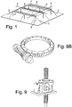
figure 1 illustrates a plant according to the present invention comprising a support structure and movement systems; -
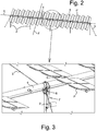
figure 2 illustrates a movement system according to the present invention installed on a row of poles of the support structure; -
figure 3 illustrates an enlarged portion offigure 2 highlighting a sustaining and movement support, arranged on each of such poles of the support structure, for the main tubes and the rotation mechanism of such main tubes; -
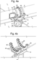
figure 4a illustrates the sustaining and movement support for the main tubes, -
figure 4b illustrates the support offigure 4a without the primary poles; -
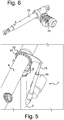
figure 5 illustrates the rotation mechanism for the main tubes; -
figure 6 illustrates a suitable actuator for such a rotation mechanism of the main tubes; -
figures 7a-7b illustrate the rotation mechanism of the secondary tubes arranged inside the main tubes; -
figures 8a-8b illustrate further motion transmission mechanisms to a worm screw for the movement of the main tubes; -
figure 9 illustrates a worm screw motion transmission mechanism for the rotation of the secondary tubes. - With reference to the quoted figures the plant for producing solar energy according to the present invention allows the movement on a first axis X and a second axis Y substantially perpendicular to each other, of devices adapted for receiving the solar light, to allow it to keep a correct orientation towards the sun. For example, such devices are photovoltaic panels or other devices adapted for capturing solar energy.
- The plant essentially comprises a support structure formed from
support poles 2 preferably kept in position by a network of tie rods orsteel bars 3, both the support poles and the tie rods being fixed in the ground through suitable pins, for example hinge pins. Such a structure can advantageously be configured two-dimensionally, for example of the "checkerboard" type and can also be installed on farmland, since it is elevated and the distance between the support poles is such as to allow the passage even of large farming machinery. - Such a support structure can alternatively be made through poles made of concrete or steel, which will have a portion driven into the ground and a part outside of the ground adapted for giving the structure the appropriate height from the ground. Said pole arrangement may or may not be connected by tie rods or steel bars.
- Systems for the movement or orientation of such solar devices are positioned on said support structure and in particular on rows of poles.
- Each movement system comprises a rotating
main tube 4 about its own axis, and installed substantially horizontally, to which a plurality ofsecondary tubes 5 is connected, preferably fixed perpendicular to the main tube in a rigid manner or alternatively through suitable systems adapted for giving the ability to rotate. The receiver devices, in the specific case illustrated the photovoltaic panels P, are fixed on such secondary tubes. - The movement system also comprises a movement mechanism for the main tubes and as an option also a movement mechanism for the secondary tubes.
- Such movement systems are fixed onto such poles through a sustaining and
movement support 6 arranged on each pole of said row, to which it is also possible to fix theaforementioned tie rods 3 and that has a housing that receives such amain tube 4 of the movement system and that allows the rotation thereof about such an axis X. - If the support structure is made through driven-in concrete poles, such a support will be given directly by the head of the pole that will be made flat, even through a
horizontal steel plate 63 suitably fixed to the pole. - In the aforementioned alternative embodiment the tie rods can be omitted and the main tube is positioned on a row of poles on the top of which the sustaining and moving supports are arranged.
- Such a
support 6 comprises a lower portion, constrained to the pole, which has fourwings 61 perpendicular to each other, each adapted for constraining one of the aforementioned tie rods. The upper portion comprises such a housing made from at least one saddle, preferably a pair ofsaddles 62, rested on the quotedhorizontal plate 63 of the support. Such saddles have a substantially circular inner profile adapted for housing the main tubes and are preferably provided along such a profile by a plurality ofbearings 64 that allow the rotation of the tube. Astrap 65 for eachsaddle 62 prevents the tube from coming out from the saddle, but does not prevent the rotation thereof inside them (for example a polyester band) - Preferably, according to the present invention, the constraint between two adjacent tubes occurs between the pair of saddles. The joining between two tubes occurs in particular by joining
flanges 41 arranged at the end of the tubes themselves. - The movement mechanism of the
main tubes 7 comprises abracket 72 crimped on the main tube and forming a unit with it. - Such a bracket is preferably arranged between the two joining
flanges 41 of two adjacent tubes and to which alinear actuator 73 is constrained, arranged between the quoted bracket and thesupport pole 2. In this way, by moving the linear actuator, exploiting the support pole as fixed pin, a rotation movement of thetube 4 is generated. For the movement of the actuator a firstelectric motor 74 is advantageously used. - The
secondary tubes 5 may or may not also internally comprise the movement mechanism 8 of the secondary tubes about the second axis. Such a mechanism is advantageously arranged in the joining area of two adjacent main tubes and comprises asecond motor 81 and atransmission mechanism 82 both constrained to the joiningflange 41 between the two main tubes through aplate 71. - The motor, through a
suitable transmission mechanism 82 sets in rotation aworm screw 83 arranged longitudinally in themain tube 4. - Such a worm screw crosses the
flange 41 and theplate 71 that supports saidtransmission system 82, and is free to rotate and thus is capable of linearly transmitting the rotation motion inside two adjacent main tubes. In this way, a single movement mechanism of the secondary tubes is capable of transmitting the rotation to two groups of secondary tubes each arranged on adjacent main tubes. Such a worm screw on both of the adjacent main tubes is connected to aconnection terminal 86 having a ball joint adapted for allowing the insertion of apin 87 that, together with thesuitable plates 84, allows the connection with arectilinear profile 85, also arranged longitudinally inside the main tube. Arack 88, constrained to such a mobile plate and that moves as a unit with it when the worm screw is set in rotation, is guided on such a profile. - The racks along their path abut a plurality of
gears 89 each fitted on a secondary tube in the position of intersection thereof with the main tube. When by means of the rotation of the worm screw the racks move, they set in rotation thegears 89 and therefore also the secondary tubes, thus the panels P about the axis Y. - The main tube is also provided with an
opening 46 closed by a cover and positioned at motors and reduction mechanisms. - Clearly, the materials for the various parts have been suitably selected for correct balancing between weight and strength.
- The movements of the motors are controlled by a suitable electronic controller that determines the angle that the panels must have through the day and in every weather condition, with feedback through a suitable inclination sensor.
- The system foresees that the main tubes be mounted on a pole with the terminations that comprise both of the adjacent movement mechanisms.
- In this way, it is possible to use a single electronic controller to control the movement of two systems simultaneously that still continue to move independently.
- The electronic board of such a controller is open to different communication systems (for example Wi-fi, RS485 or fibre optic cable). Depending on requirements, it is possible to adopt one solution rather than another.
Claims (9)
- Plant for producing solar energy comprising:• a support structure formed from support poles (2) aligned fixed to the ground,• said support poles (2) are kept in position by a network of tie rods (3),• a movement system for receiver devices of solar energy positioned on poles arranged in a row, adapted for allowing the movement of such devices about a first axis (X) and a second axis (Y) substantially perpendicular to one another, such a system comprising:• a plurality of rotating main tubes (4) about such a first axis (X), to which a plurality of secondary tubes (5) is connected, associated with said plurality of main tubes, such secondary tubes having the receiver devices (P) fixed to them,• a movement mechanism (7) for the main tubes,• a sustaining and movement support (6) arranged on each pole of said row, which has a housing that receives such main tubes (4) of the movement system and that allows the rotation thereof about such a first axis (X),wherein such a housing is made on the upper portion of such a support (6) and comprises a pair of saddle (62), arranged on a horizontal plate (63) of the support, with a substantially circular inner profile adapted for housing the rotating main tubes and for allowing the rotation thereof in the saddle about the longitudinal axis (X) of the tube, the union between two adjacent main tubes takes place between them by joining flanges (41) arranged at the end of the main tubes themselves (4),
said support (6) comprising a lower portion, constrained to the pole, which has four wings (61) perpendicular to one another each adapted for constraining one of the aforementioned tie rods to the pole. - Plant according to claim 1, wherein along such a profile there is a plurality of bearings (64) that allow the rotation of the main tubes.
- Plant according to claim 1, wherein the movement mechanism for the main tubes comprises a bracket (72), crimped on the main tube and fixedly connected with it, to which a linear actuator (73) is constrained, arranged between the mentioned bracket and the support pole (2).
- Plant according to claim 3, wherein such a bracket is arranged between the two joining flanges (41) of two adjacent tubes (4).
- Plant according to claim 1, wherein the secondary tubes rotate about a second axis (Y) substantially perpendicular to the main tubes through a movement mechanism (8).
- Plant according to claim 5, wherein the movement mechanism for the secondary tubes comprises a worm screw (83) arranged longitudinally in the main tube (4) set in rotation by suitable motor means that crosses the flange (71) arranged between the two flanges (41) in which it is free to rotate, such a worm screw is fastened through an end joint (86) and plates (84) to a rectilinear profile (85), also arranged longitudinally inside the main tube, wherein a rack (88) is guided on such a profile, said rack being constrained to such a mobile plate and moving as a unit with it when the worm screw is set in rotation, the rack along its path abuts a plurality of gears (89) each fitted on a secondary tube in the position of intersection thereof with the main tube.
- Plant according to claim 6, wherein the worm screw (83), crossing the flange (71), is capable of moving the racks of two adjacent tubes, making it possible to transmit the rotation motion to the secondary tubes arranged on two adjacent main tubes constrained on one same pole.
- Plant according to claim 1, wherein the main tube is provided with an opening (46) closed by a cover positioned at the motors and the reduction mechanisms.
- Plant according to claim 1, wherein such a structure is of the two-dimensional "checkerboard" type and is installed on farmland.
Applications Claiming Priority (2)
| Application Number | Priority Date | Filing Date | Title |
|---|---|---|---|
| IT102017000042816A IT201700042816A1 (en) | 2017-04-19 | 2017-04-19 | Plant for the production of solar energy that can be installed on agricultural land. |
| PCT/IB2018/052693 WO2018193390A1 (en) | 2017-04-19 | 2018-04-18 | Plant for producing solar energy able to be installed on farmland |
Publications (2)
| Publication Number | Publication Date |
|---|---|
| EP3612775A1 EP3612775A1 (en) | 2020-02-26 |
| EP3612775B1 true EP3612775B1 (en) | 2021-03-24 |
Family
ID=59700111
Family Applications (1)
| Application Number | Title | Priority Date | Filing Date |
|---|---|---|---|
| EP18721863.1A Active EP3612775B1 (en) | 2017-04-19 | 2018-04-18 | Plant for producing solar energy able to be installed on farmland |
Country Status (11)
| Country | Link |
|---|---|
| US (1) | US11683002B2 (en) |
| EP (1) | EP3612775B1 (en) |
| JP (1) | JP7203042B2 (en) |
| KR (1) | KR102492781B1 (en) |
| CN (1) | CN110770514A (en) |
| CA (1) | CA3060027A1 (en) |
| ES (1) | ES2874342T3 (en) |
| IL (1) | IL270050B (en) |
| IT (1) | IT201700042816A1 (en) |
| TW (1) | TWI762493B (en) |
| WO (1) | WO2018193390A1 (en) |
Families Citing this family (9)
| Publication number | Priority date | Publication date | Assignee | Title |
|---|---|---|---|---|
| JP6732940B2 (en) * | 2016-05-23 | 2020-07-29 | レム テック ソシエタ ア レスポンサビリタ リミタータ | System for covering flat surfaces |
| US11646693B2 (en) * | 2019-08-21 | 2023-05-09 | National Science Foundation | Orientation of photovoltaic modules to minimize intercepted radiation in photovoltaic aglectric systems |
| AU2021311120A1 (en) * | 2020-07-20 | 2023-02-23 | Rute Foundation Systems, Inc. | Cable and pole supported solar panel array |
| EP4264823A1 (en) * | 2020-12-18 | 2023-10-25 | Rem Tec S.R.L. | Plant for the production of solar energy that can be installed on agricultural land |
| JP7856659B2 (en) * | 2021-01-14 | 2026-05-11 | マクスン ソーラー インコーポレイテッド | Dual-axis solar cell array tracking device |
| IT202300001320A1 (en) * | 2023-01-27 | 2024-07-27 | Rem Tec S R L | ELECTRICITY PRODUCTION PLANT INCLUDING A TENSILE STRUCTURE INCLUDING GROUND SUPPORTS. |
| PL247551B1 (en) * | 2023-07-04 | 2025-07-28 | Modern Mech Spolka Z Ograniczona Odpowiedzialnoscia | Tracking installation of photovoltaic panels |
| WO2025109188A1 (en) | 2023-11-23 | 2025-05-30 | Solar Energy Systems Analytics | Photovoltaic panel device and photovoltaic power generation facility comprising at least one such device |
| FR3155850A1 (en) | 2023-11-23 | 2025-05-30 | Solar Energy Systems Analytics | Photovoltaic panel device and shade comprising such a device |
Family Cites Families (18)
| Publication number | Priority date | Publication date | Assignee | Title |
|---|---|---|---|---|
| US8459249B2 (en) * | 2007-06-15 | 2013-06-11 | Ronald P. Corio | Single axis solar tracking system |
| KR100924300B1 (en) * | 2008-04-11 | 2009-11-02 | 주식회사 솔라파크엔지니어링 | Solar position tracking device of solar collector or solar collector |
| US20100101630A1 (en) * | 2008-10-24 | 2010-04-29 | Emcore Solar Power, Inc. | Terrestrial Solar Tracking Photovoltaic Array with Slew Speed Reducer |
| US8536504B2 (en) * | 2008-10-24 | 2013-09-17 | Suncore Photovoltaics, Inc. | Terrestrial solar tracking photovoltaic array with chain drive |
| IT1398598B1 (en) | 2009-03-10 | 2013-03-08 | Dermotricos Srl | SOLAR ENERGY STATION SYSTEM |
| TWM371230U (en) * | 2009-04-27 | 2009-12-21 | qin-wen Wang | Improved sun tracking device for solar panel |
| TWI424136B (en) * | 2009-08-24 | 2014-01-21 | Herng Jiunn Liao | Two-axes solar tracker system and apparatus for solar panel and likes |
| AU2010353855A1 (en) * | 2010-05-25 | 2012-12-13 | Hans-Peter Fischer | Mounting rack for a photovoltaic module and tracking device for a photovoltaic installation |
| ITMI20101847A1 (en) * | 2010-10-08 | 2012-04-09 | Michele Giudilli | FOLLOWING SYSTEM TO UNDERSTAND SOLAR ENERGY AND RELATIVE MECHANISM OF MOVEMENT OF AN AXIS |
| US8835747B2 (en) * | 2010-12-17 | 2014-09-16 | Soitec Solar Gmbh | Components of a two-axis tracking assembly in a concentrated photovoltaic system |
| US20120152308A1 (en) * | 2010-12-17 | 2012-06-21 | Greenvolts, Inc | Structurally breaking up a two-axis tracker assembly in a concentrated photovoltaic system |
| US9482449B2 (en) | 2011-01-14 | 2016-11-01 | Sunpower Corporation | Support for solar energy collectors |
| ITBG20110048A1 (en) | 2011-11-25 | 2013-05-26 | R E M S P A Revolution Energy Maker | ENERGY PRODUCTION SYSTEM FROM RENEWABLE SOURCES |
| DE102012002551A1 (en) | 2012-02-09 | 2013-08-14 | Fraunhofer-Gesellschaft zur Förderung der angewandten Forschung e.V. | Process for the simultaneous cultivation of crops and energetic use of sunlight |
| KR101434473B1 (en) * | 2012-05-14 | 2014-08-27 | (주) 파루 | Solar electric power generation apparatus of sun location tracking type |
| FR2998044B1 (en) * | 2012-11-12 | 2018-11-02 | Saint-Augustin Canada Electric Inc. | GUIDE SYSTEM FOR SOLAR PANELS |
| AU2014213748B2 (en) * | 2013-02-05 | 2018-02-08 | Helioslite | Tracking photovoltaic solar system, and methods for installing or for using such tracking photovoltaic solar system |
| KR101868750B1 (en) * | 2017-07-26 | 2018-07-17 | 서규선 | Angle Variable Solar Module Support Structure |
-
2017
- 2017-04-19 IT IT102017000042816A patent/IT201700042816A1/en unknown
- 2017-07-14 TW TW106123676A patent/TWI762493B/en active
-
2018
- 2018-04-18 CA CA3060027A patent/CA3060027A1/en active Pending
- 2018-04-18 JP JP2019557411A patent/JP7203042B2/en active Active
- 2018-04-18 WO PCT/IB2018/052693 patent/WO2018193390A1/en not_active Ceased
- 2018-04-18 US US16/605,906 patent/US11683002B2/en active Active
- 2018-04-18 CN CN201880026161.4A patent/CN110770514A/en active Pending
- 2018-04-18 EP EP18721863.1A patent/EP3612775B1/en active Active
- 2018-04-18 KR KR1020197032470A patent/KR102492781B1/en active Active
- 2018-04-18 ES ES18721863T patent/ES2874342T3/en active Active
-
2019
- 2019-10-18 IL IL270050A patent/IL270050B/en unknown
Non-Patent Citations (1)
| Title |
|---|
| None * |
Also Published As
| Publication number | Publication date |
|---|---|
| JP7203042B2 (en) | 2023-01-12 |
| TWI762493B (en) | 2022-05-01 |
| TW201840121A (en) | 2018-11-01 |
| EP3612775A1 (en) | 2020-02-26 |
| US20200127597A1 (en) | 2020-04-23 |
| IT201700042816A1 (en) | 2018-10-19 |
| IL270050B (en) | 2021-08-31 |
| ES2874342T3 (en) | 2021-11-04 |
| KR102492781B1 (en) | 2023-01-27 |
| WO2018193390A1 (en) | 2018-10-25 |
| CA3060027A1 (en) | 2018-10-25 |
| US11683002B2 (en) | 2023-06-20 |
| JP2020518219A (en) | 2020-06-18 |
| KR20200010214A (en) | 2020-01-30 |
| CN110770514A (en) | 2020-02-07 |
Similar Documents
| Publication | Publication Date | Title |
|---|---|---|
| US11683002B2 (en) | Plant for producing solar energy able to be installed on farmland | |
| EP3682171B1 (en) | Solar power generation plant installable on agricultural installations | |
| US7000608B2 (en) | Solar energy system | |
| CA3007905C (en) | Handling system for solar energy receptor devices | |
| WO2009121174A9 (en) | Solar collector | |
| JP2015518703A (en) | Solar power tracking system | |
| WO2014122518A1 (en) | Tracking photovoltaic solar system, and methods for installing or for using such tracking photovoltaic solar system | |
| KR100779036B1 (en) | Tracked solar power system | |
| AU2018279017A1 (en) | Solar Tracking Installation | |
| US20240030859A1 (en) | Plant for the production of solar energy that can be installed on agricultural land | |
| US9353971B2 (en) | Solar generator unit | |
| KR20120015033A (en) | Rotary link module and solar power generation system having same | |
| US9732987B2 (en) | Two axis solar tracking system | |
| EP4418533B1 (en) | A dual axis solar tracking module | |
| US20250158562A1 (en) | Device and method for sunlight tracking for solar-based power generation devices |
Legal Events
| Date | Code | Title | Description |
|---|---|---|---|
| STAA | Information on the status of an ep patent application or granted ep patent |
Free format text: STATUS: UNKNOWN |
|
| STAA | Information on the status of an ep patent application or granted ep patent |
Free format text: STATUS: THE INTERNATIONAL PUBLICATION HAS BEEN MADE |
|
| PUAI | Public reference made under article 153(3) epc to a published international application that has entered the european phase |
Free format text: ORIGINAL CODE: 0009012 |
|
| STAA | Information on the status of an ep patent application or granted ep patent |
Free format text: STATUS: REQUEST FOR EXAMINATION WAS MADE |
|
| 17P | Request for examination filed |
Effective date: 20191015 |
|
| AK | Designated contracting states |
Kind code of ref document: A1 Designated state(s): AL AT BE BG CH CY CZ DE DK EE ES FI FR GB GR HR HU IE IS IT LI LT LU LV MC MK MT NL NO PL PT RO RS SE SI SK SM TR |
|
| AX | Request for extension of the european patent |
Extension state: BA ME |
|
| DAV | Request for validation of the european patent (deleted) | ||
| DAX | Request for extension of the european patent (deleted) | ||
| REG | Reference to a national code |
Ref country code: DE Ref legal event code: R079 Ref document number: 602018014395 Country of ref document: DE Free format text: PREVIOUS MAIN CLASS: F24S0030455000 Ipc: F24S0025500000 |
|
| RIC1 | Information provided on ipc code assigned before grant |
Ipc: F24S 25/10 20180101ALI20200903BHEP Ipc: F24S 30/00 20180101ALI20200903BHEP Ipc: F24S 30/455 20180101ALI20200903BHEP Ipc: F24S 30/45 20180101ALI20200903BHEP Ipc: F24S 25/50 20180101AFI20200903BHEP |
|
| GRAP | Despatch of communication of intention to grant a patent |
Free format text: ORIGINAL CODE: EPIDOSNIGR1 |
|
| STAA | Information on the status of an ep patent application or granted ep patent |
Free format text: STATUS: GRANT OF PATENT IS INTENDED |
|
| INTG | Intention to grant announced |
Effective date: 20201013 |
|
| GRAS | Grant fee paid |
Free format text: ORIGINAL CODE: EPIDOSNIGR3 |
|
| GRAA | (expected) grant |
Free format text: ORIGINAL CODE: 0009210 |
|
| STAA | Information on the status of an ep patent application or granted ep patent |
Free format text: STATUS: THE PATENT HAS BEEN GRANTED |
|
| AK | Designated contracting states |
Kind code of ref document: B1 Designated state(s): AL AT BE BG CH CY CZ DE DK EE ES FI FR GB GR HR HU IE IS IT LI LT LU LV MC MK MT NL NO PL PT RO RS SE SI SK SM TR |
|
| REG | Reference to a national code |
Ref country code: GB Ref legal event code: FG4D |
|
| REG | Reference to a national code |
Ref country code: CH Ref legal event code: EP |
|
| REG | Reference to a national code |
Ref country code: IE Ref legal event code: FG4D |
|
| REG | Reference to a national code |
Ref country code: DE Ref legal event code: R096 Ref document number: 602018014395 Country of ref document: DE Ref country code: AT Ref legal event code: REF Ref document number: 1374870 Country of ref document: AT Kind code of ref document: T Effective date: 20210415 |
|
| REG | Reference to a national code |
Ref country code: NL Ref legal event code: FP |
|
| REG | Reference to a national code |
Ref country code: LT Ref legal event code: MG9D |
|
| PG25 | Lapsed in a contracting state [announced via postgrant information from national office to epo] |
Ref country code: NO Free format text: LAPSE BECAUSE OF FAILURE TO SUBMIT A TRANSLATION OF THE DESCRIPTION OR TO PAY THE FEE WITHIN THE PRESCRIBED TIME-LIMIT Effective date: 20210624 Ref country code: BG Free format text: LAPSE BECAUSE OF FAILURE TO SUBMIT A TRANSLATION OF THE DESCRIPTION OR TO PAY THE FEE WITHIN THE PRESCRIBED TIME-LIMIT Effective date: 20210624 Ref country code: GR Free format text: LAPSE BECAUSE OF FAILURE TO SUBMIT A TRANSLATION OF THE DESCRIPTION OR TO PAY THE FEE WITHIN THE PRESCRIBED TIME-LIMIT Effective date: 20210625 Ref country code: HR Free format text: LAPSE BECAUSE OF FAILURE TO SUBMIT A TRANSLATION OF THE DESCRIPTION OR TO PAY THE FEE WITHIN THE PRESCRIBED TIME-LIMIT Effective date: 20210324 Ref country code: FI Free format text: LAPSE BECAUSE OF FAILURE TO SUBMIT A TRANSLATION OF THE DESCRIPTION OR TO PAY THE FEE WITHIN THE PRESCRIBED TIME-LIMIT Effective date: 20210324 |
|
| PG25 | Lapsed in a contracting state [announced via postgrant information from national office to epo] |
Ref country code: RS Free format text: LAPSE BECAUSE OF FAILURE TO SUBMIT A TRANSLATION OF THE DESCRIPTION OR TO PAY THE FEE WITHIN THE PRESCRIBED TIME-LIMIT Effective date: 20210324 Ref country code: LV Free format text: LAPSE BECAUSE OF FAILURE TO SUBMIT A TRANSLATION OF THE DESCRIPTION OR TO PAY THE FEE WITHIN THE PRESCRIBED TIME-LIMIT Effective date: 20210324 Ref country code: SE Free format text: LAPSE BECAUSE OF FAILURE TO SUBMIT A TRANSLATION OF THE DESCRIPTION OR TO PAY THE FEE WITHIN THE PRESCRIBED TIME-LIMIT Effective date: 20210324 |
|
| PG25 | Lapsed in a contracting state [announced via postgrant information from national office to epo] |
Ref country code: SM Free format text: LAPSE BECAUSE OF FAILURE TO SUBMIT A TRANSLATION OF THE DESCRIPTION OR TO PAY THE FEE WITHIN THE PRESCRIBED TIME-LIMIT Effective date: 20210324 Ref country code: EE Free format text: LAPSE BECAUSE OF FAILURE TO SUBMIT A TRANSLATION OF THE DESCRIPTION OR TO PAY THE FEE WITHIN THE PRESCRIBED TIME-LIMIT Effective date: 20210324 Ref country code: CZ Free format text: LAPSE BECAUSE OF FAILURE TO SUBMIT A TRANSLATION OF THE DESCRIPTION OR TO PAY THE FEE WITHIN THE PRESCRIBED TIME-LIMIT Effective date: 20210324 Ref country code: LT Free format text: LAPSE BECAUSE OF FAILURE TO SUBMIT A TRANSLATION OF THE DESCRIPTION OR TO PAY THE FEE WITHIN THE PRESCRIBED TIME-LIMIT Effective date: 20210324 |
|
| PG25 | Lapsed in a contracting state [announced via postgrant information from national office to epo] |
Ref country code: PL Free format text: LAPSE BECAUSE OF FAILURE TO SUBMIT A TRANSLATION OF THE DESCRIPTION OR TO PAY THE FEE WITHIN THE PRESCRIBED TIME-LIMIT Effective date: 20210324 Ref country code: SK Free format text: LAPSE BECAUSE OF FAILURE TO SUBMIT A TRANSLATION OF THE DESCRIPTION OR TO PAY THE FEE WITHIN THE PRESCRIBED TIME-LIMIT Effective date: 20210324 Ref country code: RO Free format text: LAPSE BECAUSE OF FAILURE TO SUBMIT A TRANSLATION OF THE DESCRIPTION OR TO PAY THE FEE WITHIN THE PRESCRIBED TIME-LIMIT Effective date: 20210324 Ref country code: PT Free format text: LAPSE BECAUSE OF FAILURE TO SUBMIT A TRANSLATION OF THE DESCRIPTION OR TO PAY THE FEE WITHIN THE PRESCRIBED TIME-LIMIT Effective date: 20210726 Ref country code: IS Free format text: LAPSE BECAUSE OF FAILURE TO SUBMIT A TRANSLATION OF THE DESCRIPTION OR TO PAY THE FEE WITHIN THE PRESCRIBED TIME-LIMIT Effective date: 20210724 |
|
| PG25 | Lapsed in a contracting state [announced via postgrant information from national office to epo] |
Ref country code: LU Free format text: LAPSE BECAUSE OF NON-PAYMENT OF DUE FEES Effective date: 20210418 |
|
| REG | Reference to a national code |
Ref country code: DE Ref legal event code: R097 Ref document number: 602018014395 Country of ref document: DE |
|
| PG25 | Lapsed in a contracting state [announced via postgrant information from national office to epo] |
Ref country code: MC Free format text: LAPSE BECAUSE OF FAILURE TO SUBMIT A TRANSLATION OF THE DESCRIPTION OR TO PAY THE FEE WITHIN THE PRESCRIBED TIME-LIMIT Effective date: 20210324 Ref country code: DK Free format text: LAPSE BECAUSE OF FAILURE TO SUBMIT A TRANSLATION OF THE DESCRIPTION OR TO PAY THE FEE WITHIN THE PRESCRIBED TIME-LIMIT Effective date: 20210324 Ref country code: AL Free format text: LAPSE BECAUSE OF FAILURE TO SUBMIT A TRANSLATION OF THE DESCRIPTION OR TO PAY THE FEE WITHIN THE PRESCRIBED TIME-LIMIT Effective date: 20210324 |
|
| PLBE | No opposition filed within time limit |
Free format text: ORIGINAL CODE: 0009261 |
|
| STAA | Information on the status of an ep patent application or granted ep patent |
Free format text: STATUS: NO OPPOSITION FILED WITHIN TIME LIMIT |
|
| PG25 | Lapsed in a contracting state [announced via postgrant information from national office to epo] |
Ref country code: SI Free format text: LAPSE BECAUSE OF FAILURE TO SUBMIT A TRANSLATION OF THE DESCRIPTION OR TO PAY THE FEE WITHIN THE PRESCRIBED TIME-LIMIT Effective date: 20210324 |
|
| 26N | No opposition filed |
Effective date: 20220104 |
|
| PG25 | Lapsed in a contracting state [announced via postgrant information from national office to epo] |
Ref country code: IE Free format text: LAPSE BECAUSE OF NON-PAYMENT OF DUE FEES Effective date: 20210418 |
|
| PG25 | Lapsed in a contracting state [announced via postgrant information from national office to epo] |
Ref country code: IS Free format text: LAPSE BECAUSE OF FAILURE TO SUBMIT A TRANSLATION OF THE DESCRIPTION OR TO PAY THE FEE WITHIN THE PRESCRIBED TIME-LIMIT Effective date: 20210724 |
|
| REG | Reference to a national code |
Ref country code: AT Ref legal event code: UEP Ref document number: 1374870 Country of ref document: AT Kind code of ref document: T Effective date: 20210324 |
|
| PG25 | Lapsed in a contracting state [announced via postgrant information from national office to epo] |
Ref country code: IT Free format text: LAPSE BECAUSE OF FAILURE TO SUBMIT A TRANSLATION OF THE DESCRIPTION OR TO PAY THE FEE WITHIN THE PRESCRIBED TIME-LIMIT Effective date: 20210324 |
|
| P01 | Opt-out of the competence of the unified patent court (upc) registered |
Effective date: 20230517 |
|
| PG25 | Lapsed in a contracting state [announced via postgrant information from national office to epo] |
Ref country code: CY Free format text: LAPSE BECAUSE OF FAILURE TO SUBMIT A TRANSLATION OF THE DESCRIPTION OR TO PAY THE FEE WITHIN THE PRESCRIBED TIME-LIMIT Effective date: 20210324 |
|
| PG25 | Lapsed in a contracting state [announced via postgrant information from national office to epo] |
Ref country code: HU Free format text: LAPSE BECAUSE OF FAILURE TO SUBMIT A TRANSLATION OF THE DESCRIPTION OR TO PAY THE FEE WITHIN THE PRESCRIBED TIME-LIMIT; INVALID AB INITIO Effective date: 20180418 |
|
| PGFP | Annual fee paid to national office [announced via postgrant information from national office to epo] |
Ref country code: GB Payment date: 20230421 Year of fee payment: 6 |
|
| PG25 | Lapsed in a contracting state [announced via postgrant information from national office to epo] |
Ref country code: MK Free format text: LAPSE BECAUSE OF FAILURE TO SUBMIT A TRANSLATION OF THE DESCRIPTION OR TO PAY THE FEE WITHIN THE PRESCRIBED TIME-LIMIT Effective date: 20210324 |
|
| PG25 | Lapsed in a contracting state [announced via postgrant information from national office to epo] |
Ref country code: MT Free format text: LAPSE BECAUSE OF FAILURE TO SUBMIT A TRANSLATION OF THE DESCRIPTION OR TO PAY THE FEE WITHIN THE PRESCRIBED TIME-LIMIT Effective date: 20210324 |
|
| GBPC | Gb: european patent ceased through non-payment of renewal fee |
Effective date: 20240418 |
|
| PG25 | Lapsed in a contracting state [announced via postgrant information from national office to epo] |
Ref country code: GB Free format text: LAPSE BECAUSE OF NON-PAYMENT OF DUE FEES Effective date: 20240418 |
|
| PG25 | Lapsed in a contracting state [announced via postgrant information from national office to epo] |
Ref country code: GB Free format text: LAPSE BECAUSE OF NON-PAYMENT OF DUE FEES Effective date: 20240418 |
|
| PGFP | Annual fee paid to national office [announced via postgrant information from national office to epo] |
Ref country code: NL Payment date: 20250423 Year of fee payment: 8 |
|
| PGFP | Annual fee paid to national office [announced via postgrant information from national office to epo] |
Ref country code: DE Payment date: 20250417 Year of fee payment: 8 |
|
| PGFP | Annual fee paid to national office [announced via postgrant information from national office to epo] |
Ref country code: ES Payment date: 20250519 Year of fee payment: 8 |
|
| PGFP | Annual fee paid to national office [announced via postgrant information from national office to epo] |
Ref country code: BE Payment date: 20250417 Year of fee payment: 8 |
|
| PGFP | Annual fee paid to national office [announced via postgrant information from national office to epo] |
Ref country code: FR Payment date: 20250422 Year of fee payment: 8 |
|
| PGFP | Annual fee paid to national office [announced via postgrant information from national office to epo] |
Ref country code: CH Payment date: 20250501 Year of fee payment: 8 |
|
| PGFP | Annual fee paid to national office [announced via postgrant information from national office to epo] |
Ref country code: AT Payment date: 20250416 Year of fee payment: 8 |
|
| PG25 | Lapsed in a contracting state [announced via postgrant information from national office to epo] |
Ref country code: TR Free format text: LAPSE BECAUSE OF FAILURE TO SUBMIT A TRANSLATION OF THE DESCRIPTION OR TO PAY THE FEE WITHIN THE PRESCRIBED TIME-LIMIT Effective date: 20210324 |
|
| REG | Reference to a national code |
Ref country code: CH Ref legal event code: U11 Free format text: ST27 STATUS EVENT CODE: U-0-0-U10-U11 (AS PROVIDED BY THE NATIONAL OFFICE) Effective date: 20260501 |