EP3612410B1 - Correction de trajet d'un véhicule par rapport à une trajectoire de vol magnétique projetée - Google Patents
Correction de trajet d'un véhicule par rapport à une trajectoire de vol magnétique projetée Download PDFInfo
- Publication number
- EP3612410B1 EP3612410B1 EP18787950.7A EP18787950A EP3612410B1 EP 3612410 B1 EP3612410 B1 EP 3612410B1 EP 18787950 A EP18787950 A EP 18787950A EP 3612410 B1 EP3612410 B1 EP 3612410B1
- Authority
- EP
- European Patent Office
- Prior art keywords
- vehicle
- guideway
- track segment
- levitation
- deviation
- Prior art date
- Legal status (The legal status is an assumption and is not a legal conclusion. Google has not performed a legal analysis and makes no representation as to the accuracy of the status listed.)
- Active
Links
- 238000005339 levitation Methods 0.000 claims description 141
- 238000000034 method Methods 0.000 claims description 62
- 239000000725 suspension Substances 0.000 claims description 21
- 230000008859 change Effects 0.000 claims description 17
- 230000003287 optical effect Effects 0.000 claims description 14
- 239000011295 pitch Substances 0.000 description 47
- 230000033001 locomotion Effects 0.000 description 7
- 230000006870 function Effects 0.000 description 6
- 230000008878 coupling Effects 0.000 description 4
- 238000010168 coupling process Methods 0.000 description 4
- 238000005859 coupling reaction Methods 0.000 description 4
- 230000015654 memory Effects 0.000 description 4
- 238000005516 engineering process Methods 0.000 description 3
- 230000008569 process Effects 0.000 description 3
- CWYNVVGOOAEACU-UHFFFAOYSA-N Fe2+ Chemical compound [Fe+2] CWYNVVGOOAEACU-UHFFFAOYSA-N 0.000 description 2
- 230000003466 anti-cipated effect Effects 0.000 description 2
- 230000004907 flux Effects 0.000 description 2
- 239000000463 material Substances 0.000 description 2
- 230000010355 oscillation Effects 0.000 description 2
- 239000003973 paint Substances 0.000 description 2
- 230000004044 response Effects 0.000 description 2
- 239000012080 ambient air Substances 0.000 description 1
- 238000004891 communication Methods 0.000 description 1
- 230000003247 decreasing effect Effects 0.000 description 1
- 238000001514 detection method Methods 0.000 description 1
- 230000005484 gravity Effects 0.000 description 1
- 229910052751 metal Inorganic materials 0.000 description 1
- 238000012986 modification Methods 0.000 description 1
- 230000004048 modification Effects 0.000 description 1
- 230000002093 peripheral effect Effects 0.000 description 1
- 230000003068 static effect Effects 0.000 description 1
- 239000002887 superconductor Substances 0.000 description 1
Images


Classifications
-
- B—PERFORMING OPERATIONS; TRANSPORTING
- B60—VEHICLES IN GENERAL
- B60L—PROPULSION OF ELECTRICALLY-PROPELLED VEHICLES; SUPPLYING ELECTRIC POWER FOR AUXILIARY EQUIPMENT OF ELECTRICALLY-PROPELLED VEHICLES; ELECTRODYNAMIC BRAKE SYSTEMS FOR VEHICLES IN GENERAL; MAGNETIC SUSPENSION OR LEVITATION FOR VEHICLES; MONITORING OPERATING VARIABLES OF ELECTRICALLY-PROPELLED VEHICLES; ELECTRIC SAFETY DEVICES FOR ELECTRICALLY-PROPELLED VEHICLES
- B60L13/00—Electric propulsion for monorail vehicles, suspension vehicles or rack railways; Magnetic suspension or levitation for vehicles
- B60L13/04—Magnetic suspension or levitation for vehicles
- B60L13/06—Means to sense or control vehicle position or attitude with respect to railway
- B60L13/08—Means to sense or control vehicle position or attitude with respect to railway for the lateral position
-
- B—PERFORMING OPERATIONS; TRANSPORTING
- B60—VEHICLES IN GENERAL
- B60L—PROPULSION OF ELECTRICALLY-PROPELLED VEHICLES; SUPPLYING ELECTRIC POWER FOR AUXILIARY EQUIPMENT OF ELECTRICALLY-PROPELLED VEHICLES; ELECTRODYNAMIC BRAKE SYSTEMS FOR VEHICLES IN GENERAL; MAGNETIC SUSPENSION OR LEVITATION FOR VEHICLES; MONITORING OPERATING VARIABLES OF ELECTRICALLY-PROPELLED VEHICLES; ELECTRIC SAFETY DEVICES FOR ELECTRICALLY-PROPELLED VEHICLES
- B60L13/00—Electric propulsion for monorail vehicles, suspension vehicles or rack railways; Magnetic suspension or levitation for vehicles
- B60L13/10—Combination of electric propulsion and magnetic suspension or levitation
-
- B—PERFORMING OPERATIONS; TRANSPORTING
- B60—VEHICLES IN GENERAL
- B60L—PROPULSION OF ELECTRICALLY-PROPELLED VEHICLES; SUPPLYING ELECTRIC POWER FOR AUXILIARY EQUIPMENT OF ELECTRICALLY-PROPELLED VEHICLES; ELECTRODYNAMIC BRAKE SYSTEMS FOR VEHICLES IN GENERAL; MAGNETIC SUSPENSION OR LEVITATION FOR VEHICLES; MONITORING OPERATING VARIABLES OF ELECTRICALLY-PROPELLED VEHICLES; ELECTRIC SAFETY DEVICES FOR ELECTRICALLY-PROPELLED VEHICLES
- B60L2240/00—Control parameters of input or output; Target parameters
- B60L2240/10—Vehicle control parameters
- B60L2240/22—Yaw angle
-
- B—PERFORMING OPERATIONS; TRANSPORTING
- B60—VEHICLES IN GENERAL
- B60L—PROPULSION OF ELECTRICALLY-PROPELLED VEHICLES; SUPPLYING ELECTRIC POWER FOR AUXILIARY EQUIPMENT OF ELECTRICALLY-PROPELLED VEHICLES; ELECTRODYNAMIC BRAKE SYSTEMS FOR VEHICLES IN GENERAL; MAGNETIC SUSPENSION OR LEVITATION FOR VEHICLES; MONITORING OPERATING VARIABLES OF ELECTRICALLY-PROPELLED VEHICLES; ELECTRIC SAFETY DEVICES FOR ELECTRICALLY-PROPELLED VEHICLES
- B60L2240/00—Control parameters of input or output; Target parameters
- B60L2240/60—Navigation input
- B60L2240/62—Vehicle position
-
- B—PERFORMING OPERATIONS; TRANSPORTING
- B60—VEHICLES IN GENERAL
- B60L—PROPULSION OF ELECTRICALLY-PROPELLED VEHICLES; SUPPLYING ELECTRIC POWER FOR AUXILIARY EQUIPMENT OF ELECTRICALLY-PROPELLED VEHICLES; ELECTRODYNAMIC BRAKE SYSTEMS FOR VEHICLES IN GENERAL; MAGNETIC SUSPENSION OR LEVITATION FOR VEHICLES; MONITORING OPERATING VARIABLES OF ELECTRICALLY-PROPELLED VEHICLES; ELECTRIC SAFETY DEVICES FOR ELECTRICALLY-PROPELLED VEHICLES
- B60L2240/00—Control parameters of input or output; Target parameters
- B60L2240/60—Navigation input
- B60L2240/64—Road conditions
- B60L2240/642—Slope of road
-
- Y—GENERAL TAGGING OF NEW TECHNOLOGICAL DEVELOPMENTS; GENERAL TAGGING OF CROSS-SECTIONAL TECHNOLOGIES SPANNING OVER SEVERAL SECTIONS OF THE IPC; TECHNICAL SUBJECTS COVERED BY FORMER USPC CROSS-REFERENCE ART COLLECTIONS [XRACs] AND DIGESTS
- Y02—TECHNOLOGIES OR APPLICATIONS FOR MITIGATION OR ADAPTATION AGAINST CLIMATE CHANGE
- Y02T—CLIMATE CHANGE MITIGATION TECHNOLOGIES RELATED TO TRANSPORTATION
- Y02T10/00—Road transport of goods or passengers
- Y02T10/60—Other road transportation technologies with climate change mitigation effect
- Y02T10/72—Electric energy management in electromobility
-
- Y—GENERAL TAGGING OF NEW TECHNOLOGICAL DEVELOPMENTS; GENERAL TAGGING OF CROSS-SECTIONAL TECHNOLOGIES SPANNING OVER SEVERAL SECTIONS OF THE IPC; TECHNICAL SUBJECTS COVERED BY FORMER USPC CROSS-REFERENCE ART COLLECTIONS [XRACs] AND DIGESTS
- Y02—TECHNOLOGIES OR APPLICATIONS FOR MITIGATION OR ADAPTATION AGAINST CLIMATE CHANGE
- Y02T—CLIMATE CHANGE MITIGATION TECHNOLOGIES RELATED TO TRANSPORTATION
- Y02T90/00—Enabling technologies or technologies with a potential or indirect contribution to GHG emissions mitigation
- Y02T90/10—Technologies relating to charging of electric vehicles
- Y02T90/16—Information or communication technologies improving the operation of electric vehicles
Definitions
- the present disclosure relates to controlling a vehicle during magnetic flight along a guideway. More specifically, the present disclosure relates to minimizing vertical deviation from a projected flight path of the vehicle during magnetic flight along the guideway.
- Transportation systems are designed to move people and cargo over distances.
- Transportation systems can include vehicles configured to traverse a roadway, track, guideway, and the like.
- Vehicles often include suspension systems that modify the motion and/or orientation of passenger or cargo compartments to reduce or attenuate vibrations or other unwanted motions relative to the track.
- vibrations For example, in the context of magnetic transportation systems, magnetic fields between the vehicle and conductive plates of the track can be adjusted to reduce vibrations.
- the vehicle may be lifted or levitated by vertical forces such as eddy currents in the conductive plates.
- a control system can adjust these vertical forces such that the vehicle follows a projected path along the track.
- EP 2 933 132 does disclose a controlled magnetic suspension. However, it does not determine a 3-D deviation. Rather using D1 as exemplary, the determinations are a reactive type system that determines a "disturbance force" measured by "means 8 located at the vehicle head.” as explained in [0064]. It says at the end of [0064]: "This way the disturbance energy is recycled and used for smooth levitation (Maglevsuspension, propulsion, guidance etc.). Thus, the detection done by D1 is only at a single point of the vehicle and it is not in relation to the 3-D deviation, but in the direction for that particular means. It is based on the means for registering a force as explained in paragraphs [0016] and [0017].
- the task of this invention is it to adjust the path of the vehicle in 3-D relative to a detected 3-D deviation of the track.
- This task is solved by a method for guiding a vehicle over a flight path, the method comprising the steps as outlined in independent claim 1.
- levitation refers to the lifting and suspension of an object relative to another object in the absence of a mechanical contact between the objects.
- "Levitation force” is a force that provides for levitation. The levitation force can act in a vertical direction (the direction opposite the direction of gravity), but the same force can be used to move or position two objects in a lateral direction or in some direction with both vertical and lateral components.
- the terms “levitation” and “levitation force” as used herein refer, respectively, to contactless positioning and a force between two objects in a direction substantially orthogonal to the primary direction of travel.
- levitation magnetic flux and “levitation force” are interchangeable and refer to the same element.
- a “levitation generator” is a device that is configured to generate magnetic waves that interact with a lifting member to levitate the movable object with respect to the stationary object.
- Drive force refers to the force required to accelerate, maintain motion or decelerate one object with respect to another.
- drive force means a force substantially in line with the primary direction of travel, effected without mechanical contact between the two objects.
- drive magnetic flux means a force substantially in line with the primary direction of travel, effected without mechanical contact between the two objects.
- drive magnetic flux means a force substantially in line with the primary direction of travel, effected without mechanical contact between the two objects.
- drive magnetic flux magnetomagnetic drive force
- drive force are interchangeable and refer to the same element.
- a “drive generator” is a device that is configured to generate magnetic waves that interact with a drive member to drive the movable object with respect to the stationary object.
- a “guideway” or “track” refers to components or structure that provides a path for a vehicle (e.g., car, bogie, transport apparatus, etc.) traveling between two locations.
- vehicle e.g., car, bogie, transport apparatus, etc.
- the term guideway and/or track are interchangeable and refer to the same element.
- a vehicle refers to a device which is configured for travel along the guideway.
- the vehicle can be at least partially enclosed, entirely enclosed or have a surface upon which objects or persons can be placed.
- the vehicle can be coupled with a bogie which is in turn coupled with the guideway.
- the bogie can be an integral component of the vehicle or a separate component to which the vehicle can be coupled with.
- a bogie as used herein does not necessarily include wheels, but instead is configured for engagement with the guideway.
- a “controller” is generally a computer (carried on the vehicle) that executes a program to analyze data, make decisions, and send out commands.
- the controller can be an electronic device including, but not limited to, a processor, microprocessor, memory (ROM and/or RAM), and/or storage devices.
- the controller can be a commercial off-the-shelf (COTS) electronic device, or a specially designed for implementation with the control system.
- COTS commercial off-the-shelf
- Coupled refers to the linking or connection of two objects.
- the coupling can be direct or indirect.
- An indirect coupling includes connecting two objects through one or more intermediary objects.
- Coupling can also refer to electrical or mechanical connections.
- Coupling can also include magnetic linking without physical contact.
- substantially refers to an element essentially conforming to the particular dimension, shape or other word that substantially modifies, such that the component need not be exact. For example, substantially cylindrical means that the object resembles a cylinder, but can have one or more deviations from a true cylinder.
- the term “comprising” means "including, but not necessarily limited to”; it specifically indicates openended inclusion or membership in a so-described combination, group, series and the like.
- a “magnetic source” is any material that naturally produces a magnetic field or can be induced to generate a magnetic field.
- a magnetic source can include a permanent magnet, an electromagnet, a superconductor, or any other material that produces a magnetic field or can be induced to generate a magnetic field.
- roll is defined as a rotation or oscillation about a longitudinal, or X axis; the longitudinal axis spanning between the front and the rear.
- Pitch is defined as the vertical angle of the long axis of the levitation generator relative to the travel direction. Pitch is the rotation or oscillation of about a transverse, or Z axis, the transverse axis being perpendicular to the longitudinal axis where the transverse axis spans between two sides.
- altitude refers to a distance of the midpoint or pivot point of the levitation generator from the top or bottom of the guideway.
- Flight path refers to a set of three-dimensional coordinates that define an intended or a projected path for a vehicle over a guideway or track.
- the term flight path may be used interchangeable with the term projected flight path herein.
- the present disclosure is directed to a technique for guiding a vehicle over a flight path relative to a guideway or track.
- These techniques include, for example, a method performed by a vehicle (e.g., and/or sub-components thereof) where a controller of the vehicle receives guideway data generated or stored by one or more guideway sensors (e.g., optical sensors, encoders, radio frequency identification sensors (RFID), radar sensors, etc.) associated with a metallic track.
- the guideway data can include, for example, information corresponding to a track segment disposed between two or more supports.
- the guideway sensors may transmit guideway data from a database that contains information describing track segments, the set of coordinates of the flight path, deflections, etc.
- the method further includes receiving, at the controller, flight path data (e.g., a set of coordinates in three-dimensional (3-D) space) relating to a flight path or a projected flight path for the vehicle as well as determining an amount of deviation between one or more coordinates of the flight path data and a position of the vehicle based on the guideway data.
- flight path data e.g., a set of coordinates in three-dimensional (3-D) space
- the method also includes adjusting, by a magnetic suspension system, the position of the vehicle relative to the track segment to minimize the amount of deviation in at least one dimension in the 3-D space.
- adjusting the position of the vehicle relative to the track segment includes adjusting at least one of an altitude, a longitude, or a latitude of the vehicle.
- the vehicle can include a magnetic suspension system having one or more levitation generators.
- the levitation generators may be adjusted to provide more/less levitation force and/or an angle of the levitation generator (relative to the track segment) may be changed to modify the position and/or orientation (e.g., pitch, roll, and/or yaw) of the vehicle relative to the track segment to minimize the amount of deviation.
- the levitation generators may be individually or independently adjusted or they may be adjusted in cooperation or concert.
- the vehicle can include one or more drive generators operable to provide a drive force that provides a velocity to the vehicle.
- the drive generator(s) can be adjusted to change the velocity of the vehicle relative to the track segment to minimize the amount of deviation in one or more dimensions of the 3-D space. For example, a vehicle traveling at a higher or faster velocity may produce less deflection in the track segment. Accordingly, increasing the velocity of the vehicle may minimize the amount of deviation. Alternatively, in some embodiments, a lower or slower velocity may produce less deflection in the track segment such that decreasing the velocity of the vehicle can minimize the amount of deviation.
- the drive generator(s) may cooperate and act in conjunction with the levitation generators to change the vehicle's position relative to the track segment. With respect to the velocity of the vehicle, the method includes steps to determine the velocity based on optical sensors, encoders, and/or radar sensors.
- the method also describes determining the deflection of the track segment.
- the guideway data can include a length corresponding to the track segment.
- the controller receives the guideway data, as discussed above, and determines the amount of deflection in the 3-D space based on the length of the track segment and a velocity of the vehicle relative to the length of the track segment. For example, certain relationships may exist and define the deflection of the track segment based on a known length of a track segment, the weight of the vehicle and/or the speed or velocity of the vehicle traversing the length track segment. In this fashion, the controller can determine the estimated or anticipated deflection over the track segment and thus, the amount of deviation between coordinates of the flight path data and a position of the vehicle.
- present disclosure includes a method controlling altitude of a vehicle moving along a guideway for magnetic flight.
- the method receives, at a controller, data generated by one or more sensors.
- the method also receives, at the controller, data relating to a flight path of the vehicle.
- the controller determines a speed of the vehicle relative to the guideway for magnetic flight and calculates a deviation of the vehicle from the flight path.
- the controller adjusts the altitude of the vehicle relative to the guideway for magnetic flight by changing certain aspects of a magnetic flight suspension system causing the vehicle to more closely track the flight path.
- the sensors include at least one sensor associated with a corresponding control device.
- the at least one sensor can be an ultrasonic sensor, and the control device can be a levitation generator.
- the controller receives a sensed horizontal velocity from one of an optical sensor, an encoder, an RFID, or a forward looking radar.
- the altitude of the vehicle of the guideway for magnetic flight is determined by the controller receiving data from an altitude sensor which can be at least one of a laser sensor, an optical sensor, a camera sensor, a mechanical sensor, or a magnetic sensor.
- the received data relating to a flight path of the vehicle is from a database that contains information describing guideway segments.
- the data is the corresponding guideway segments of an intended flight path based on a starting and ending destination of the vehicle.
- the deviation of the vehicle from the projected flight path is calculated by taking a difference of the flight path and a current position of the vehicle relative to the guideway, where the deviation can be in three dimensions, thereby determining roll, altitude, and pitch.
- Certain aspects of the magnetic flight suspension system can be changed by varying an angle of one or more of a plurality of levitation generators.
- the angle of each of the levitation generators can be varied independent from another and can be adjusted by a drive motor.
- a drive generator can be varied to produce a different velocity of the vehicle in changing the magnetic flight suspension system.
- the present disclosure is also directed to a system configured to control a vehicle moving along a guideway for magnetic flight.
- the system can include a plurality of levitation generators which has at least one sensor associated therewith, a plurality of sensors operable to detect position relative to the guideway, and a controller including at least one processor unit which is operably coupled to the plurality of sensors.
- the controller can be configured to receive data generated by the plurality of sensors and data relating to a flight path of the vehicle.
- the controller can also determine an altitude of the vehicle relative to the guideway and a speed, using one or more of the plurality of sensors, of the vehicle relative to the guideway for magnetic flight.
- the controller can then calculate a deviation of the vehicle from the flight path and transmit data to adjust the altitude of the vehicle relative to the guideway for magnetic flight by changing certain aspects of a magnetic flight suspension system causing the vehicle to more closely track the flight path.
- the present disclosure is also directed to a method controlling altitude of a vehicle moving along a guideway for magnetic flight.
- the method includes receiving, at a controller, data generated by one or more sensors and data relating to a flight path of the vehicle.
- the controller determines an altitude of the vehicle relative to the guideway for magnetic flight and a speed of the vehicle relative to the guideway for magnetic flight.
- the controller then calculates the deviation of the vehicle from the flight path and levitation modulation required to reduce the deviation from the magnetic flight path.
- Levitation modulation signals are sent to one or more levitation generators.
- the controller adjusts the altitude of the vehicle relative to the guideway for magnetic flight by levitation modulation equivalent to the deviation from the flight path thereby maintaining a path closer to the flight path
- guideway constructed in a substantially horizontal plane
- present disclosure and techniques disclosed herein are equally applicable to vertically oriented guideways, inclined guideways, and/or combinations thereof.
- the system can more closely resemble an elevator.
- the guideway can include component that are horizontal, vertical, angled, or any combination thereof.
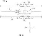
- FIG. 1A illustrates an example of a levitation transportation system 100 with a vehicle 102 within or entering a guideway 106.
- the guideway 106 is formed by a plurality of track segments or track pieces disposed between supports 108.
- Supports 108 provide structural integrity and support for each guideway 106 piece or track segment.
- the guideway 106 pieces can have various lengths 110 and are often made of metallic elements (e.g., ferrous, non-ferrous, etc.). While the illustrated example shows a segment of the guideway 106 having supports 108 on opposing ends, to the segmented track can include supports 108 that have varying arrangements, such as having a center support with secondary supports extending therefrom.
- the guideway 106 pieces can form a network of track allowing a vehicle 102 to move within the levitation transportation system 100. While the segmented guideway 106 piece that is illustrated spans the portion between two supports 108, the piece can be a portion of the span and be joined to another guideway 106 pieces on either side, such that a plurality of pieces span the portion between the two supports 108.
- the vehicle 102 has a magnetic flight suspension system 101 operates to adjust a position of vehicle 102 relative to guideway 106 to more closely follow a flight path 111.
- the magnetic flight suspension system 101 can include a control device 10 as well as a plurality of levitation generators 104.
- the plurality of levitation generators 104 can be at least partially received within the guideway 106 and allows the vehicle 102 to travel within the levitation transportation system 100.
- the levitation generators 104 can magnetically engage and interact with the guideway 106 to guide the vehicle 102 along the transportation system 100.
- the levitation generators 104 and the guideway 106 are typically physically separated by a distance as the vehicle 102 travels within the levitation transportation system 100.
- the levitation generators 104 generate a magnetic force or levitation force to elevate the vehicle 102 above or at a spaced distance (but within the segmented track) from the guideway 106.
- One or more levitation generators 104 can be implemented.
- FIG. 1A shows two levitation generators 104, but in other illustrated examples, as in FIG. 1B , four levitation generators 104 are used, with two more levitation generators 104 positioned cross-sectionally parallel with to the two shown levitation generators 104 in FIG. 1 .
- the four levitation generators 104 can each pitch, or rotate about a Z axis, to adjust the altitude, roll, and/or pitch of the vehicle 102.
- the levitation generators 104 can be operable to adjust pitch by varying an angle of one or more of the levitation generator 104. As such, the levitation generators 104 can adjust the altitude, roll, and/or pitch of the vehicle 102 by varying the combination of the levitation generators 104, which will be described in further detail below. As the levitation generators 104 can be independently operated or adjusted from one another, the vehicle 102 can be adjusted in three dimensions relative to the guideway 106. The levitation generators 104 can be adjusted by a drive motor 1040.
- each levitation generator 104 is coupled to an individual drive motor 1040, while in other embodiments, multiple levitation generators 104 may be coupled to more than one levitation generator 104 such that a single drive motor 1040 adjusts two corresponding levitation generators 104 (e.g., using varying gear ratios, etc.).
- the levitation generator 104 can operate in accordance with the levitation generators described in U.S. Pat. No. 9,090,167, issued on July 28, 2015 , the entire contents of which are incorporated herein by reference.
- the magnetic flight suspension system 101 can also include changing and varying a drive generator 103.
- One or more drive generators can be included in the levitation transportation system 100.
- the drive generator 103 is configured to provide a drive force. Varying the drive force produced by the drive generator 103 produces thrust and accelerates the vehicle 102 to a particular velocity.
- the drive generator 103 may produce an angular drive force that can include lift force components as well as thrust force components. In this fashion, drive generator 103 may cooperate with the levitation generators 104 to elevate or lift the vehicle 102 (or portions thereof) above the guideway 106. In some embodiments, higher or faster velocities correspond with greater lift forces.
- Varying the drive force between each of the four levitation generators 104 and the drive generator 103 can adjust the altitude 118 of the vehicle 102 relative to the ground and/or relative to segments of the guideway 106.
- the drive generator can operate in accordance with the drive generator described in U.S. Pat. No. 9,090,167 mentioned above.
- the vehicle 102 can include a controller 114 capable of changing, adjusting, or otherwise instructing magnetic flight suspension system 101, including levitation generator 104, drive generator 103 (and combinations thereof) to alter the position of the vehicle 102 to more closely follow the flight path 111.
- the controller 114 may instruct the magnetic flight suspension system to maintain a predetermined altitude 118 relative to the ground as the vehicle 102 traverses the guideway 106.
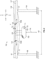
- the guideway 106 as shown in FIG. 2 , can have a deflection 116 over the length 110 of the guideway 106 in the flight path 111 (or projected flight path) of the vehicle 102. The deflection 116 can occur due to a variety of different factors.
- the deflection 116 can occur because of a change of path in the guideway 106. In other examples, the deflection 116 can occur due to the weight of the guideway 106 itself. Additionally, the deflection 116 can occur because of the weight of one or more vehicles 102 traveling along the guideway 106.
- the deflection 116 in the flight path 111 can be a vertical deflection, as in FIG. 2 , a pitch deflection, as in FIG. 4 , a rotational deflection, as in FIG. 5 , or a combination thereof. For a vertical deflection, the altitude of the vehicle is adjusted; for a pitch deflection, the pitch of the vehicle is adjusted; and for a rotational deflection, the roll of the vehicle is adjusted.
- the controller 114 by changing certain aspects of the magnetic flight suspension system 101, can adjust the roll, altitude, and/or pitch of the vehicle 102 to offset for the deflection 116 of the guideway 106 in the flight path 111 and more closely track the flight path 111.
- the controller 114 can be configured to receive and determine information about the vehicle 102 and guideway 106.
- the controller 114 can be a processor, microprocessor, computer, server, or any other electronic device capable of determining the deflection of the length 110 of guideway 106 in response to information received from one or more sensors.
- the vehicle 102 can also be adjusted by the controller 114 changing certain aspects of the magnetic flight suspension system 101 to adjust to variations of the vehicle 102 to more closely track the flight path 111. For example, as will be further discussed below, passengers, in the vehicle 102, can move around which may cause unwanted rotation, such as rotation about the X axis.
- the controller 114 can adjust individual levitation generators 104 to correct the position of the vehicle 102.
- the controller 114 receives relevant information or data related to the levitation transportation system 100 such as the flight path 111, the altitude 118, the spacing of supports 108, and the length 110 of the segmented track.
- the received data relating to the flight path 111 of the vehicle 102 is from a database that contains information describing segments of the guideway 106.
- the data relating to the flight path 111 of the vehicle 102 is based on the corresponding guideway segments 106 of an intended flight path based on a starting and ending destination of the vehicle 102.
- the controller 114 can receive data from an altitude sensor 112.
- the altitude sensor 112 can be located in the vehicle 102, or in other examples, the altitude sensor 112 can be located in the guideway 106 and/or the supports 108.
- the altitude sensor 112 can be at least one of a laser sensor, an optical sensor, a camera sensor, a mechanical sensor, a magnetic sensor, or any suitable sensor to determine altitude of the vehicle 102.
- the controller 114 can also determine information such as the weight and speed of the vehicle 102. In determining the speed of the vehicle 102 relative to the guideway 106 for magnetic flight, the controller 114 receives a sensed horizontal velocity. The horizontal velocity is in relation to the guideway 106.
- the speed of the vehicle 102 can be based on data received from one of an optical sensor, an encoder, an RFID, a forward looking radar, or any other suitable sensor or method to determine speed of the vehicle 102.
- the weight of the vehicle 102 can include the weight of the vehicle 102, weight of passengers, payload, cargo, or any combination thereof.
- the controller 114 determines the weight of the vehicle 102 instantaneously.
- the controller 114 determines, instantaneously, the weight of the vehicle 102, along with contents of the vehicle 102, which can include one or more of the passengers, payload, and/or cargo.
- the controller 114 receives the weight of the vehicle 102 at launch of the vehicle 102 within the levitation transportation system 100.
- the controller 114 can receive data from one or more sensors 120 coupled with the levitation transportation system 100.
- the one or more sensors 120 can be disposed on the vehicle 102, the guideway 106, and/or the supports 108.
- the one or more sensors 120 can be optical, radio, and/or near field communicator configured to determine altitude, speed, weight, location, or any combination thereof.
- the one or more sensors 120 provide the controller 114 with data necessary to determine deflection 116 of the guideway 106.
- the one or more sensors 120 include at least one sensor 105 associated with a corresponding control device 10, such as a levitation generator 104.
- the one or more sensors include at least four ultrasonic sensors 105, each of which is associated with a corresponding levitation generator 104. As illustrated, the sensor 105 is coupled with the levitation generator 104; in other examples, the sensor 105 can be coupled elsewhere, for example the vehicle 102.
- the one or more sensors 105 can be ultrasonic sensors configured to interact with the guideway 106.
- the one or more sensors 120 can include laser sensors configured to encode and/or transmit data between adjacent vehicles 102.
- the encoded/transmitted data can be the length 110 of segmented track, deflection of the segmented track, speed of adjacent vehicles, weight of adjacent vehicles, and/or any other data necessary to the controller 114.
- the one or more sensors 120 can be communicatively coupled with a transmitter 122 which can be disposed on the support 108 to receive data relative to the length 110 of guideway 106.
- the data assists the controller 114 in determining the anticipated deflection 116 of the upcoming length 110 of guideway 106 as the vehicle 102 travels along the guideway 106. Also, the data assists the controller 114 in determining any deviation of the vehicle 102 from the flight path 111.
- At least one of the one or more sensors 120 can communicate with the transmitter 122 disposed on the support 108 to receive data relating the length 110 of the guideway segment 106.
- the transmitter 122 can be a barcode 124, such as a Quick Response (QR) code, a radio frequency identification (RFID) tag, or similar device configured to provide data to the one or more sensors 120.
- QR Quick Response
- RFID radio frequency identification
- the transmitter 122 can be disposed on the support 108, the guideway 106, or any portion of the levitation transportation system 100 with communication range of the one or more sensors 120. In the illustrated example, the transmitter 122 is on the support 108. The transmitter 122 can be located at different portions of the levitation transportation system 100. For example, the transmitter 122 can be located on the guideway 106 at a joint or in the middle.
- the data associated with the transmitter 122 can be static or dynamic. In situations where the data associated with the transmitter 122 is dynamic, the data received by the vehicle 102 can include the weight of the preceding vehicle(s) 102, the temperature of the rail, the ambient air temperature, the weight of the following vehicle(s) 102, or any other necessary information.
- the transmitter 122 can store data relating to the flight path 111, for example the length 110 or path of the guideway 106 between two or more supports 108. In FIG. 1 , the transmitter 122 communicates the length 110 of guideway 106 between two supports 108. In other examples, the transmitter 122 can communicate data relating to two or more lengths 110 of guideway 106, thus reducing the total number of transmitters 122 necessary within the levitation transportation system 100.
- the controller 114 after receiving data generated by the one or more sensors 120, data relating to the flight path 111 of the vehicle 102, and after determining the altitude 118 and the speed of the vehicle 102 relative to the guideway for magnetic flight, calculates the a deviation of the vehicle 102 from the flight path 111.
- the deviation of the vehicle 102 from the flight path 111 can occur because of deflection of the guideway 106 or other factors such as wind, passenger movement, or other factors.
- the deviation of the vehicle 102 from the flight path 111 can also occur because of factors such as the speed based on the rotation of the drive generator 103, angles of the levitation generators 104, weight of the vehicle 102, or any other possible factors.
- the controller 114 then calculates a levitation modulation required to reduce the deviation from the flight path 111 and sends levitation modulation signals to one or more levitation generators 104 such that the levitation generators 104 adjust its pitch.
- the controller 114 adjusts the altitude of the vehicle 102 relative to the guideway for magnetic flight by levitation modulation equivalent to the deviation from the flight path 111, thereby maintaining a path closer to the flight path 111.
- Modulation of the angle or pitch of the levitation generators 104 change the lift vector at each levitation generator 104, thus affecting the vertical motion of the vehicle 102.
- the combination of changing angles or pitches of individual levitation generators 104 permits the controller 114 to adjust the vehicle 102 in terms of altitude, roll, and/or pitch.
- FIG. 2 illustrates a vehicle 102 within a deflected length 110 of guideway 106 of a levitation transportation system 100.
- the length 110 of guideway 106 can be deflected from the weight of the vehicle 102 or is deflected because of the flight path 111. As illustrated in FIG. 2 , the deflection is temporary and the guideway 106 returns to the original altitude.
- the slope of the guideway 106 in the flight path 111 can have different gradients or be extended over a longer distance.
- the height of the guideway 106 may not return to its previous height, for example if the vehicle 102 is to be returned to the ground.
- the deflection 116 is mathematically predictable and can be calculated using the known weight and speed of the vehicle 102, and length 110 of the guideway 106.
- the controller 114 calculates the deviation of the vehicle 102 from the flight path 111 and is able to determine the deviation in terms of the altitude, roll and/or pitch.
- the controller 114 calculates the deviation of the vehicle 102 by taking a difference of the flight path 111 and a current position of the vehicle 102 relative to the guideway 106.
- the controller 114 can calculate the deflection 116 of the guideway 106 in view of the vehicle 102 weight, speed, and the length 110 of the guideway 106.
- the controller 114 then adjusts the levitation of the vehicle 102 to accommodate for the deflection 116 and maintain the predetermined altitude 118.
- the controller 114 can adjust the levitation or altitude of the vehicle 102 to maintain the predetermined altitude 118 in a number of ways including, but not limited to, increasing the speed of the vehicle 102 or adjusting the pitch of the levitation generators 104, thereby generating more levitation, as illustrated in FIG.3 .
- FIG. 2 illustrates a vehicle 102 having the levitation generators 104 pitched to increase levitation relative to the levitation generator of FIG. 1 , thereby maintaining the predetermined altitude 118.
- the levitation generators 104 collective pitch upward or downward as desired such that the vehicle 102 maintains balance. For example, to lower the altitude, the levitation generators 104 can collectively pitch downward. Conversely to raise the altitude, the levitation generators 104 can collectively pitch upward.
- the guideway 106 can have one or more markings 107 disposed on an inner surface thereof.
- the one or more markings 107 can correspond to the intended or projected flight path on guideway 106.
- the one or more markings 107 can be physical markings such as colored paint, reflective tape, reflective paint, or may include overlaid/projected markings such as laser light, and so on.
- the markings 107 provide a contrast with the inner surface of the guideway 106 and may be optically recognized or sensed by components controller 114.
- the one or more markings 107 can be disposed on the inner surface to project a level flight path under different guideway 106 situations, i.e. one vehicle, two vehicles, three vehicles.
- the sensors 105 on the levitation generators 104 can be capable of determining their position relative to the flight path 111 and/or one or more markings 107, thereby maintaining a level flight path.
- the sensors 105 can detect deviations between the marking 107 and instruct the controller 114 to adjust the pitch of the levitation generator 104 to maintain the level flight path.
- the controller 114 can have pre-calculated deflection stored therein for each guideway 106 under various circumstances.
- the controller 114 can adjust the levitation generator 104 and altitude sensors from one marking 107 to another marking 107 if conditions of the transportation system 100 change, for example a vehicle entering/exiting the guideway 106.
- FIG. 3 illustrates a vehicle 102 having an increased speed relative to the segmented track while having a levitation generator 104 with a substantially similar pitch to the levitation generator 104 of FIG. 1 .
- the drive generator 103 can increase the speed relative to the guideway 106 which increases the levitating force generated by the levitation generator 104, thus allowing the vehicle 102 to maintain the predetermined altitude 118.
- the controller 114 adjusts the levitation of the vehicle 102 to maintain a substantially linear direction of travel, the predetermined altitude 118. Similarly, the altitude of the vehicle 102 may change due to other factors such as passenger weight or movement, or wind. The controller 114 can also adjust the altitude of the vehicle 102 to cause the vehicle 102 to more closely track the flight path 111.
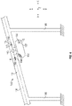
- the controller 114 can adjust the pitch of the vehicle 102 to account for the deflection of and more closely track the substantially non-horizontal segmented guideway 102, as illustrated in FIG. 4 .
- FIG. 4 is illustrated with a continuous downward slope, the pitch of the vehicle 102 may be adjusted to compensate for an upward slope, varying slopes, and/or any vertical deflection such that the pitch of the vehicle 102 is adjusted to more closely track the guideway 106 and flight path 111.
- the pitch of the vehicle 102 may be adjusted to compensate shifting or unbalance of weight within the vehicle 102 between the front and rear of the vehicle 102. In FIG.
- the guideway 106 has a downward slope such that the pitch of the vehicle 102 is adjusted to more closely track the flight path 111 within the guideway 106.
- the pitch of the vehicle 102 can be adjusted by changing the pitch or angle between the front and rear levitation generators 104. As such, to compensate for a higher end such that that end of the vehicle 102 is to be lowered, the levitation generators 104 on the higher end pitch downward and/or the levitation generators 104 on the lower end can pitch upward. Conversely, to compensate for a lower end such that that end of the vehicle 102 is to be raised, the levitation generators 104 on the lower end pitch upward and/or the levitation generators 104 on the higher end can pitch downward.
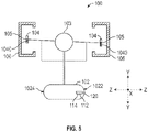
- FIG. 5 is a front view of the transportation system 100, illustrating changing of certain aspects of a magnetic flight suspension system 101 causing the vehicle 102 to rotate, or roll, to more closely track the flight path 111.
- the deviation of the vehicle 102 from the projected flight path is illustrated as a roll.
- the controller 114 calculates the deviation of the vehicle 102 from the flight path 111 and is able to determine the deviation as roll.
- the controller 114 calculates the deviation of the vehicle 102 by taking a difference of the flight path 111 and a current position of the vehicle 102 relative to the guideway 106.
- the vehicle 102 may rotate or roll because of many factors, including movement of passengers, wind, change in direction, or any other possible factors.
- Individual or paired levitation generators 104 can be adjusted to cause the vehicle 102 to more closely track the flight path 111 and/or to correct any unwanted roll.
- the vehicle 102 may roll about the X axis to more closely track the desired flight path 111 or correct any unwanted alignment.
- the levitation generators 104 on the low side can pitch upward and/or the levitation generators 104 on the high side can pitch downward.
- the vehicle 102 has rolled such that the right side 1022 (from the illustrated perspective) has dropped to a lower altitude than the left side 1024.
- the levitation generators 104 on the right side can pitch upward and/or the levitation generators 104 on the left side can pitch downward. If the vehicle 102 has rolled such that the left side 1024 has dropped to a lower altitude than the right side 1022, and/or to rotate the vehicle 102 in a clockwise direction (from the illustrated perspective, the levitation generators 104 on the left side can pitch upward and/or the levitation generators 104 on the right side can pitch downward.
- the number of vehicles in a length 110 of guideway 106 can vary depending on the length 110 of the segmented track, the vehicle 102 speed, the spacing between vehicles, the number of vehicles in the levitation transportation system 100, and/or the frequency/popularity of the path. Certain routes, destinations, or segmented guideways 106 can have a different use rate changing the potential number of vehicles 102 within a length 110 of guideway 106.
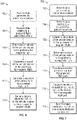
- the example method 600 is provided by way of example, as there are a variety of ways to carry out the method 600.
- the method 600 described below can be carried out using the configurations illustrated in FIGS. 1-5 , for example.
- Each block shown in FIG. 6 represents one or more processes, methods or subroutines, carried out in the example method 600.
- the illustrated order of blocks is illustrative only and the order of the blocks can change according to the present disclosure. Additional blocks may be added or fewer blocks may be utilized, without departing from this disclosure.
- the example method 600 can begin at block 602.
- the method 600 receives, at the controller, data generated by one or more sensors.
- the one or more sensors includes at least one sensor associated with a corresponding control device.
- the control device can be a levitation generator, and the at least one sensor can be an ultrasonic sensor.
- the one or more sensors includes at least four ultrasonic sensors, each of which is associated with a corresponding levitation generator.
- the method 600 receives, at the controller, data relating to a projected flight path of the vehicle.
- the projected flight path of the vehicle can be from a database that contains information describing guideway segments.
- the data can be corresponding guideway segments of an intended flight path based on a starting and ending destination of the vehicle.
- the method 600 determines, at the controller, an altitude of the vehicle relative to the guideway for magnetic flight.
- the controller can receive data from an altitude sensor.
- the altitude sensor can include at least one of a laser sensor, an optical sensor, a camera sensor, a mechanical sensor, a magnetic sensor, or any other suitable sensor.
- the method 600 determines, at the controller, a speed of the vehicle relative to the guideway for magnetic flight.
- the controller may receive a sensed horizontal velocity.
- the speed of the vehicle can be based on data received from one of an optical sensor, an encoder, an RFID, a forward looking radar, or any other suitable sensor or method.
- the method 600 calculates, at the controller, a deviation of the vehicle from the projected flight path.
- the controller can take a difference of the projected flight path and a current position of the vehicle relative to the guideway.
- the controller is able to calculate the deviation in three dimensions, thereby determining roll, altitude, and pitch.
- the method 600 transmits, from the controller, data to adjust the altitude of the vehicle relative to the guideway for magnetic flight by changing certain aspects of a magnetic flight suspension system causing the vehicle to more closely track the projected flight path.
- the vehicle can be adjusted by varying an angle of one or more of a plurality of levitation generators.
- the angle of each of the plurality of levitation generators can be varied independent from one another, and the angle of each of the plurality of levitation generators can be adjusted by a drive motor.
- a drive generator can be varied to produce a different velocity of the vehicle.
- the example method 700 is provided by way of example, as there are a variety of ways to carry out the method 700.
- the method 800 described below can be carried out using the configurations illustrated in FIGS. 1-5 , for example.
- Each block shown in FIG. 7 represents one or more processes, methods or subroutines, carried out in the example method 700.
- the illustrated order of blocks is illustrative only and the order of the blocks can change according to the present disclosure. Additional blocks may be added or fewer blocks may be utilized, without departing from this disclosure.
- the example method 700 can begin at block 702.
- the method 700 receives, at the controller, data generated by one or more sensors.
- the one or more sensors includes at least one sensor associated with a corresponding control device.
- the control device can be a levitation generator, and the at least one sensor can be an ultrasonic sensor.
- the one or more sensors includes at least four ultrasonic sensors, each of which is associated with a corresponding levitation generator.
- the method 700 receives, at the controller, data relating to a projected flight path of the vehicle.
- the projected flight path of the vehicle can be from a database that contains information describing guideway segments.
- the data can be corresponding guideway segments of an intended flight path based on a starting and ending destination of the vehicle.
- the method 700 determines, at the controller, an altitude of the vehicle relative to the guideway for magnetic flight.
- the controller can receive data from an altitude sensor.
- the altitude sensor can include at least one of a laser sensor, an optical sensor, a camera sensor, a mechanical sensor, a magnetic sensor, or any other suitable sensor.
- the method 700 determines, at the controller, a speed of the vehicle relative to the guideway for magnetic flight.
- the controller may receive a sensed horizontal velocity.
- the speed of the vehicle can be based on data received from one of an optical sensor, an encoder, an RFID, a forward looking radar, or any other suitable sensor or method.
- the method 700 calculates, at the controller, a deviation of the vehicle from the projected flight path.
- the controller can take a difference of the projected flight path and a current position of the vehicle relative to the guideway.
- the controller is able to calculate the deviation in three dimensions, thereby determining roll, altitude, and pitch.
- the method 700 calculates, at the controller, levitation modulation required to reduce the deviation from the magnetic flight path.
- the levitation modulation can be in terms of roll, altitude, and/or pitch.
- the method 700 sends, from the controller, levitation modulation signals to one or more levitation generators.
- the controller adjusts the altitude of the vehicle relative to the guideway for magnetic flight by levitation modulation equivalent to the deviation from the projected flight path thereby maintaining a path closer to the projected flight path.
- the vehicle can be adjusted by varying an angle of one or more of a plurality of levitation generators.
- the angle of each of the plurality of levitation generators can be varied independent from one another, and the angle of each of the plurality of levitation generators can be adjusted by a drive motor.
- a drive generator can be varied to produce a different velocity of the vehicle.
- Such instructions can comprise, for example, instructions and data which cause or otherwise configure a general purpose computer, special purpose computer, or special purpose processing device to perform a certain function or group of functions. Portions of computer resources used can be accessible over a network.
- the computer executable instructions may be, for example, binaries, intermediate format instructions such as assembly language, firmware, or source code. Examples of computer-readable media that may be used to store instructions, information used, and/or information created during methods according to described examples include magnetic or optical disks, flash memory, USB devices provided with non-volatile memory, networked storage devices, and so on.
- devices implementing methods according to these disclosures can comprise hardware, firmware and/or software, and can take any of a variety of form factors.
- Typical examples of such form factors include laptops, smart phones, small form factor personal computers, personal digital assistants, and so on.
- Functionality described herein also can be embodied in peripherals or add-in cards. Such functionality can also be implemented on a circuit board among different chips or different processes executing in a single device, by way of further example. Instructions, media for conveying such instructions, computing resources for executing them, and other structures for supporting such computing resources are means for providing the functions described in these disclosures. Accordingly this description is to be taken only by way of example and not to otherwise limit the scope of the embodiments herein.
Landscapes
- Engineering & Computer Science (AREA)
- Physics & Mathematics (AREA)
- Electromagnetism (AREA)
- Power Engineering (AREA)
- Transportation (AREA)
- Mechanical Engineering (AREA)
- Control Of Vehicles With Linear Motors And Vehicles That Are Magnetically Levitated (AREA)
- Vehicle Waterproofing, Decoration, And Sanitation Devices (AREA)
- Non-Portable Lighting Devices Or Systems Thereof (AREA)
- Navigation (AREA)
Claims (12)
- Procédé pour guider un véhicule (110) sur une trajectoire de vol (111), le proceed comprenant:la réception, par un contrôleur (114) du véhicule (110), de données de voie de guidage (106) générées par un ou plusieurs capteurs de voie de guidage associés à une piste métallique, les données de voie de guidage (106) comprenant des informations correspondant à un segment de piste disposé entre deux ou plusieurs supports (108);recevoir, par le contrôleur (114), des données de trajectoire de vol pour le véhicule (110), les données de trajectoire de vol représentant un ensemble de coordonnées dans un espace tridimensionnel (3-D);déterminer, par le contrôleur (114), une quantité de déviation 3D entre une ou plusieurs coordonnées des données de trajectoire de vol et une position du véhicule (110) sur la base des données de voie de guidage (106); etajuster, par un système de suspension magnétique (101), l'orientation du véhicule (110) par rapport au segment de piste pour minimiser la quantité de déviation 3D dans au moins une dimension dans l'espace 3D;dans lequel les données de la voie de guidage (106) comprennent en outre une longueur du segment de voie, dans lequel la détermination de la quantité de déviation 3-D comprend en outre:la détermination, au niveau du contrôleur, d'une déviation du segment de voie dans l'espace tridimensionnel basée au moins sur la longueur du segment de voie et une vitesse du véhicule (102, 110) par rapport à la longueur du segment de voie;déterminer, au niveau du contrôleur, la quantité de déviation entre les une ou plusieurs coordonnées des données de trajectoire de vol et la position du véhicule sur la base de la déviation du segment de piste.
- Procédé de la revendication 1, dans lequel le système de suspension magnétique (101) comprend une pluralité de générateurs de lévitation (104), dans lequel l'ajustement de la position du véhicule par rapport au segment de piste comprend en outre:la modification d'un angle d'au moins un générateur de lévitation (104) de la pluralité de générateurs de lévitation (104) par rapport au segment de voie pour minimiser la quantité de déviation 3D dans la au moins une dimension dans l'espace 3D;changer une force de lévitation au niveau d'un ou de plusieurs générateurs de lévitation (104) pour minimiser la quantité de déviation 3D dans l'au moins une dimension dans l'espace 3D;changer indépendamment l'angle de chaque générateur de lévitation (104) de la pluralité de générateurs de lévitation (104).
- Le procédé de la revendication 1, comprenant en outre:
le réglage, au niveau d'un générateur d'entraînement (103), d'une force d'entraînement pour modifier une vitesse du véhicule par rapport au segment de piste afin de minimiser la quantité de déviation 3D dans au moins une dimension dans l'espace 3D. - Le procédé de la revendication 3, comprenant en outre:
la détermination de la vitesse du véhicule (110) par rapport au segment de voie sur la base d'un capteur optique, d'un encodeur ou de capteurs radar (105, 120). - Procédé de la revendication 1, dans lequel le ou les capteurs de la voie de guidage (106) comprennent un capteur optique (105, 120), un encodeur, un capteur d'identification par radiofréquence (RFID) ou un capteur radar à balayage frontal.
- Procédé de la revendication 1, dans lequel la réception des données de la voie de guidage (106) comprend en outre:
La réception des données de voie de guidage (106) à partir d'une base de données qui contient des informations décrivant des segments de voie et l'ensemble de coordonnées des données de trajectoire de vol. - Le procédé de la revendication 1, comprenant en outre:
déterminer au moins l'un d'un tangage, d'un roulis ou d'un lacet du véhicule par rapport au segment de piste sur la base de la quantité de déviation 3D. - Système pour guider un véhicule sur une trajectoire de vol, le système comprenant:une pluralité de capteurs de voie de guidage (106) associés à une piste métallique, la pluralité de capteurs de voie de guidage (106) génère des données de voie de guidage (106) correspondant à un ou plusieurs segments de piste disposés entre deux ou plusieurs supports (108), dans lequel les données de voie de guidage (106) comprennent une longueur du segment de piste;une pluralité de générateurs de sustentation (104) qui fournissent une sustentation à un véhicule (110) par rapport à un segment de voie; etun contrôleur (114) comprenant au moins une unité de traitement configurée pour:recevoir des données de voie de guidage (106) générées par un ou plusieurs capteurs de voie de guidage (106) associés à une voie métallique, les données de voie de guidage (106) comprenant des informations correspondant à un segment de voie disposé entre deux ou plusieurs supports (108);recevoir des données de trajectoire de vol pour le véhicule, les données de trajectoire de vol représentant un ensemble de coordonnées dans un espace tridimensionnel (3-D);déterminer une quantité de déviation 3D entre une ou plusieurs coordonnées des données de trajectoire de vol et une position du véhicule basée sur les données de la voie de guidage (106); etajuster un ou plusieurs des générateurs de lévitation (104) pour changer l'orientation du véhicule par rapport au segment de voie pour minimiser la quantité de déviation 3D dans au moins une dimension dans l'espace 3D;déterminer une déviation du segment de piste dans l'espace 3-D sur la base d'au moins la longueur du segment de piste et d'une vitesse du véhicule par rapport à la longueur du segment de piste ; et déterminer la quantité de déviation entre les une ou plusieurs coordonnées des données de trajectoire de vol et la position du véhicule sur la base de la déviation du segment de piste.
- Système de la revendication 8,dans lequel l'unité de traitement est en outre configurée pour changer un angle d'au moins un générateur de lévitation (104) par rapport au segment de piste pour minimiser la quantité de déviation dans la au moins une dimension dans l'espace 3D;dans lequel l'unité de traitement est en outre configurée pour modifier une force de lévitation au niveau d'un ou plusieurs générateurs de lévitation (104) pour minimiser la quantité de déviation 3D dans la au moins une dimension dans l'espace 3D;dans lequel l'unité de traitement est en outre configurée pour modifier indépendamment l'angle de chaque générateur de lévitation (104) de la pluralité de générateurs de lévitation (104).
- Le système de la revendication 8, comprenant en outre:
au moins un générateur d'entraînement (103) qui fournit une force d'entraînement correspondant à une vitesse du véhicule par rapport au segment de piste, dans lequel l'unité de traitement est en outre configurée pour ajuster le au moins un générateur d'entraînement (103) pour changer la vitesse du véhicule par rapport au segment de piste afin de minimiser la quantité de déviation 3D dans au moins une dimension dans l'espace 3D. - Un support tangible, non-transitoire, lisible par ordinateur ayant des instructions codées sur celui-ci, les instructions, lorsqu'elles sont exécutées par un processeur, sont utilisables pour:recevoir des données de voie de guidage (106) générées par un ou plusieurs capteurs de voie de guidage (106) associés à une piste métallique, les données de voie de guidage (106) comprenant des informations correspondant à un segment de piste disposé entre deux ou plusieurs supports (108), dans lequel les données de voie de guidage (106) comprennent en outre une longueur du segment de piste;recevoir des données de trajectoire de vol pour un véhicule configuré pour traverser le segment de voie, les données de trajectoire de vol représentant un ensemble de coordonnées dans un espace tridimensionnel (3-D);déterminer une quantité de déviation 3D entre une ou plusieurs coordonnées des données de trajectoire de vol et une position du véhicule sur la base des données de la voie de guidage (106) ; etordonner à un système de suspension magnétique (101) d'ajuster l'orientation du véhicule par rapport au segment de voie pour minimiser la quantité de déviation 3D dans au moins une dimension dans l'espace 3D;déterminer, au niveau du contrôleur, une déviation du segment de voie dans l'espace 3-D sur la base au moins de la longueur du segment de voie et d'une vitesse du véhicule par rapport à la longueur du segment de voie ; et déterminer la quantité de déviation entre les une ou plusieurs coordonnées des données de trajectoire de vol et la position du véhicule sur la base de la déviation du segment de voie.
- Support tangible, non transitaire, lisible par ordinateur de la revendication 11, dans lequel les instructions, lorsqu'elles sont exécutées par le processeur, sont en outre utilisables pour:
ajuster un angle d'au moins un générateur de lévitation (104) du véhicule par rapport au segment de voie pour minimiser la quantité de déviation 3D dans au moins une dimension dans l'espace 3D ; et ajuster une force d'entra nement produite par un générateur d'entra nement (103) pour changer une vitesse du véhicule par rapport au segment de voie pour minimiser la quantité de déviation 3D dans la au moins une dimension dans l'espace 3D.
Applications Claiming Priority (2)
| Application Number | Priority Date | Filing Date | Title |
|---|---|---|---|
| US201762486860P | 2017-04-18 | 2017-04-18 | |
| PCT/US2018/028187 WO2018195213A1 (fr) | 2017-04-18 | 2018-04-18 | Correction de trajet d'un véhicule par rapport à une trajectoire de vol magnétique projetée |
Publications (3)
| Publication Number | Publication Date |
|---|---|
| EP3612410A1 EP3612410A1 (fr) | 2020-02-26 |
| EP3612410A4 EP3612410A4 (fr) | 2021-04-21 |
| EP3612410B1 true EP3612410B1 (fr) | 2022-10-26 |
Family
ID=63856022
Family Applications (1)
| Application Number | Title | Priority Date | Filing Date |
|---|---|---|---|
| EP18787950.7A Active EP3612410B1 (fr) | 2017-04-18 | 2018-04-18 | Correction de trajet d'un véhicule par rapport à une trajectoire de vol magnétique projetée |
Country Status (7)
| Country | Link |
|---|---|
| US (1) | US11447018B2 (fr) |
| EP (1) | EP3612410B1 (fr) |
| JP (1) | JP7239486B2 (fr) |
| CN (1) | CN111051118A (fr) |
| ES (1) | ES2936522T3 (fr) |
| IL (1) | IL270013B2 (fr) |
| WO (1) | WO2018195213A1 (fr) |
Families Citing this family (1)
| Publication number | Priority date | Publication date | Assignee | Title |
|---|---|---|---|---|
| WO2017205546A1 (fr) * | 2016-05-24 | 2017-11-30 | Skytran, Inc. | Commande d'altitude le long d'une piste segmentée |
Citations (1)
| Publication number | Priority date | Publication date | Assignee | Title |
|---|---|---|---|---|
| US5904101A (en) * | 1997-04-22 | 1999-05-18 | Power Superconductor Applications Co., Inc. | Auxiliary propulsion for magnetically levitated vehicle |
Family Cites Families (13)
| Publication number | Priority date | Publication date | Assignee | Title |
|---|---|---|---|---|
| US4924778A (en) * | 1988-03-30 | 1990-05-15 | Kabushiki Kaisha Toshiba | Attraction type magnetic levitating apparatus |
| JPH01315204A (ja) * | 1988-03-30 | 1989-12-20 | Toshiba Corp | 吸引式磁気浮上装置 |
| US6871597B1 (en) * | 2002-07-17 | 2005-03-29 | Lockheed Martin Corporation | Magnetically levitated transporter |
| US6920870B2 (en) * | 2003-12-10 | 2005-07-26 | Stuart Minica | Arrow support by magnetic levitation |
| CN101692315B (zh) * | 2009-09-25 | 2011-08-10 | 民航总局空管局技术中心 | 基于实时雷达数据的高精度4d飞机航迹分析方法 |
| EP2726320B1 (fr) * | 2011-06-30 | 2018-06-20 | Skytran | Système d'entraînement pour système de transport |
| US9701319B2 (en) * | 2013-08-12 | 2017-07-11 | Gonzalo Duran Ariza | Transportation systems |
| EP2933132A1 (fr) * | 2014-04-14 | 2015-10-21 | Quantum Trains International B.V. | Suspension magnétique controlée |
| AU2015311740A1 (en) * | 2014-09-05 | 2017-04-20 | Skytran Inc. | Vertical switching in a magnetic levitation guideway transportation system |
| US9261354B1 (en) * | 2014-10-24 | 2016-02-16 | Edward J. Mercado | System and process for measuring deflection |
| US10322729B2 (en) * | 2014-12-30 | 2019-06-18 | The Suppes Facility Trust | Terreplane transportation system |
| WO2016126496A1 (fr) * | 2015-02-08 | 2016-08-11 | Hyperloop Technologies, Inc | Système de transport |
| US10207723B2 (en) * | 2015-02-19 | 2019-02-19 | Elwha Llc | Train suspension control systems and methods |
-
2018
- 2018-04-18 WO PCT/US2018/028187 patent/WO2018195213A1/fr unknown
- 2018-04-18 US US16/606,718 patent/US11447018B2/en active Active
- 2018-04-18 JP JP2019556678A patent/JP7239486B2/ja active Active
- 2018-04-18 CN CN201880040798.9A patent/CN111051118A/zh active Pending
- 2018-04-18 EP EP18787950.7A patent/EP3612410B1/fr active Active
- 2018-04-18 ES ES18787950T patent/ES2936522T3/es active Active
-
2019
- 2019-10-17 IL IL270013A patent/IL270013B2/en unknown
Patent Citations (1)
| Publication number | Priority date | Publication date | Assignee | Title |
|---|---|---|---|---|
| US5904101A (en) * | 1997-04-22 | 1999-05-18 | Power Superconductor Applications Co., Inc. | Auxiliary propulsion for magnetically levitated vehicle |
Also Published As
| Publication number | Publication date |
|---|---|
| JP2020518212A (ja) | 2020-06-18 |
| EP3612410A1 (fr) | 2020-02-26 |
| ES2936522T3 (es) | 2023-03-17 |
| US20200130514A1 (en) | 2020-04-30 |
| IL270013B2 (en) | 2023-05-01 |
| WO2018195213A1 (fr) | 2018-10-25 |
| JP7239486B2 (ja) | 2023-03-14 |
| IL270013B1 (en) | 2023-01-01 |
| IL270013A (fr) | 2019-12-31 |
| CN111051118A (zh) | 2020-04-21 |
| US11447018B2 (en) | 2022-09-20 |
| EP3612410A4 (fr) | 2021-04-21 |
Similar Documents
| Publication | Publication Date | Title |
|---|---|---|
| EP3465070B1 (fr) | Commande d'altitude le long d'une piste segmentée | |
| US20180194246A1 (en) | Adaptive Magnetic Suspension of Vehicle with Adjustment of Lifting Power | |
| Delimpaltadakis et al. | Decentralized platooning with obstacle avoidance for car-like vehicles with limited sensing | |
| CN109867103B (zh) | 自动搬运车 | |
| US11890946B2 (en) | Levitation control system for a transportation system | |
| EP3612410B1 (fr) | Correction de trajet d'un véhicule par rapport à une trajectoire de vol magnétique projetée | |
| US20230278433A1 (en) | Path correction of a vehicle relative to projected magnetic flight path | |
| US20220111735A1 (en) | Vehicle for travelling along a linear route guideway | |
| CN209946709U (zh) | 一种agv小车的车载控制器控制系统 | |
| US20220379736A1 (en) | Path correction of a vehicle relative to projected magnetic flight path | |
| JP2020518212A5 (fr) | ||
| WO2009067116A1 (fr) | Système de contrôle pour un véhicule | |
| Van Goethem et al. | Design and Simulation of a Magnetic Levitation Conveyor Vehicle | |
| JPH01126115A (ja) | 磁気浮上搬送車の停止制御方式 | |
| IT9021702A1 (it) | Impianto per il trasporto di carichi pallettizzati con veicoli a guida automatica. |
Legal Events
| Date | Code | Title | Description |
|---|---|---|---|
| STAA | Information on the status of an ep patent application or granted ep patent |
Free format text: STATUS: THE INTERNATIONAL PUBLICATION HAS BEEN MADE |
|
| PUAI | Public reference made under article 153(3) epc to a published international application that has entered the european phase |
Free format text: ORIGINAL CODE: 0009012 |
|
| STAA | Information on the status of an ep patent application or granted ep patent |
Free format text: STATUS: REQUEST FOR EXAMINATION WAS MADE |
|
| 17P | Request for examination filed |
Effective date: 20191017 |
|
| AK | Designated contracting states |
Kind code of ref document: A1 Designated state(s): AL AT BE BG CH CY CZ DE DK EE ES FI FR GB GR HR HU IE IS IT LI LT LU LV MC MK MT NL NO PL PT RO RS SE SI SK SM TR |
|
| AX | Request for extension of the european patent |
Extension state: BA ME |
|
| RIN1 | Information on inventor provided before grant (corrected) |
Inventor name: BAERTSCH, ROBERT Inventor name: WAMBLE III, JOHN LEE Inventor name: FOSTER, CLARK B. Inventor name: COLE, JOHN |
|
| DAV | Request for validation of the european patent (deleted) | ||
| DAX | Request for extension of the european patent (deleted) | ||
| A4 | Supplementary search report drawn up and despatched |
Effective date: 20210318 |
|
| RIC1 | Information provided on ipc code assigned before grant |
Ipc: B60L 13/06 20060101AFI20210312BHEP Ipc: B60L 13/04 20060101ALI20210312BHEP Ipc: B60L 13/08 20060101ALI20210312BHEP Ipc: B60L 13/10 20060101ALI20210312BHEP |
|
| STAA | Information on the status of an ep patent application or granted ep patent |
Free format text: STATUS: EXAMINATION IS IN PROGRESS |
|
| 17Q | First examination report despatched |
Effective date: 20220104 |
|
| GRAP | Despatch of communication of intention to grant a patent |
Free format text: ORIGINAL CODE: EPIDOSNIGR1 |
|
| STAA | Information on the status of an ep patent application or granted ep patent |
Free format text: STATUS: GRANT OF PATENT IS INTENDED |
|
| INTG | Intention to grant announced |
Effective date: 20220706 |
|
| GRAS | Grant fee paid |
Free format text: ORIGINAL CODE: EPIDOSNIGR3 |
|
| GRAA | (expected) grant |
Free format text: ORIGINAL CODE: 0009210 |
|
| STAA | Information on the status of an ep patent application or granted ep patent |
Free format text: STATUS: THE PATENT HAS BEEN GRANTED |
|
| AK | Designated contracting states |
Kind code of ref document: B1 Designated state(s): AL AT BE BG CH CY CZ DE DK EE ES FI FR GB GR HR HU IE IS IT LI LT LU LV MC MK MT NL NO PL PT RO RS SE SI SK SM TR |
|
| REG | Reference to a national code |
Ref country code: GB Ref legal event code: FG4D |
|
| REG | Reference to a national code |
Ref country code: CH Ref legal event code: EP |
|
| REG | Reference to a national code |
Ref country code: DE Ref legal event code: R096 Ref document number: 602018042317 Country of ref document: DE |
|
| REG | Reference to a national code |
Ref country code: AT Ref legal event code: REF Ref document number: 1526810 Country of ref document: AT Kind code of ref document: T Effective date: 20221115 |
|
| REG | Reference to a national code |
Ref country code: IE Ref legal event code: FG4D |
|
| RAP4 | Party data changed (patent owner data changed or rights of a patent transferred) |
Owner name: SKYTRAN, INC. |
|
| REG | Reference to a national code |
Ref country code: NL Ref legal event code: FP |
|
| REG | Reference to a national code |
Ref country code: SE Ref legal event code: TRGR |
|
| REG | Reference to a national code |
Ref country code: LT Ref legal event code: MG9D |
|
| REG | Reference to a national code |
Ref country code: NO Ref legal event code: T2 Effective date: 20221026 |
|
| REG | Reference to a national code |
Ref country code: AT Ref legal event code: MK05 Ref document number: 1526810 Country of ref document: AT Kind code of ref document: T Effective date: 20221026 |
|
| REG | Reference to a national code |
Ref country code: ES Ref legal event code: FG2A Ref document number: 2936522 Country of ref document: ES Kind code of ref document: T3 Effective date: 20230317 |
|
| PG25 | Lapsed in a contracting state [announced via postgrant information from national office to epo] |
Ref country code: PT Free format text: LAPSE BECAUSE OF FAILURE TO SUBMIT A TRANSLATION OF THE DESCRIPTION OR TO PAY THE FEE WITHIN THE PRESCRIBED TIME-LIMIT Effective date: 20230227 Ref country code: LT Free format text: LAPSE BECAUSE OF FAILURE TO SUBMIT A TRANSLATION OF THE DESCRIPTION OR TO PAY THE FEE WITHIN THE PRESCRIBED TIME-LIMIT Effective date: 20221026 Ref country code: FI Free format text: LAPSE BECAUSE OF FAILURE TO SUBMIT A TRANSLATION OF THE DESCRIPTION OR TO PAY THE FEE WITHIN THE PRESCRIBED TIME-LIMIT Effective date: 20221026 Ref country code: AT Free format text: LAPSE BECAUSE OF FAILURE TO SUBMIT A TRANSLATION OF THE DESCRIPTION OR TO PAY THE FEE WITHIN THE PRESCRIBED TIME-LIMIT Effective date: 20221026 |
|
| PG25 | Lapsed in a contracting state [announced via postgrant information from national office to epo] |
Ref country code: RS Free format text: LAPSE BECAUSE OF FAILURE TO SUBMIT A TRANSLATION OF THE DESCRIPTION OR TO PAY THE FEE WITHIN THE PRESCRIBED TIME-LIMIT Effective date: 20221026 Ref country code: PL Free format text: LAPSE BECAUSE OF FAILURE TO SUBMIT A TRANSLATION OF THE DESCRIPTION OR TO PAY THE FEE WITHIN THE PRESCRIBED TIME-LIMIT Effective date: 20221026 Ref country code: LV Free format text: LAPSE BECAUSE OF FAILURE TO SUBMIT A TRANSLATION OF THE DESCRIPTION OR TO PAY THE FEE WITHIN THE PRESCRIBED TIME-LIMIT Effective date: 20221026 Ref country code: IS Free format text: LAPSE BECAUSE OF FAILURE TO SUBMIT A TRANSLATION OF THE DESCRIPTION OR TO PAY THE FEE WITHIN THE PRESCRIBED TIME-LIMIT Effective date: 20230226 Ref country code: HR Free format text: LAPSE BECAUSE OF FAILURE TO SUBMIT A TRANSLATION OF THE DESCRIPTION OR TO PAY THE FEE WITHIN THE PRESCRIBED TIME-LIMIT Effective date: 20221026 Ref country code: GR Free format text: LAPSE BECAUSE OF FAILURE TO SUBMIT A TRANSLATION OF THE DESCRIPTION OR TO PAY THE FEE WITHIN THE PRESCRIBED TIME-LIMIT Effective date: 20230127 |
|
| P01 | Opt-out of the competence of the unified patent court (upc) registered |
Effective date: 20230524 |
|
| PGFP | Annual fee paid to national office [announced via postgrant information from national office to epo] |
Ref country code: NL Payment date: 20230426 Year of fee payment: 6 |
|
| REG | Reference to a national code |
Ref country code: DE Ref legal event code: R097 Ref document number: 602018042317 Country of ref document: DE |
|
| PG25 | Lapsed in a contracting state [announced via postgrant information from national office to epo] |
Ref country code: SM Free format text: LAPSE BECAUSE OF FAILURE TO SUBMIT A TRANSLATION OF THE DESCRIPTION OR TO PAY THE FEE WITHIN THE PRESCRIBED TIME-LIMIT Effective date: 20221026 Ref country code: RO Free format text: LAPSE BECAUSE OF FAILURE TO SUBMIT A TRANSLATION OF THE DESCRIPTION OR TO PAY THE FEE WITHIN THE PRESCRIBED TIME-LIMIT Effective date: 20221026 Ref country code: EE Free format text: LAPSE BECAUSE OF FAILURE TO SUBMIT A TRANSLATION OF THE DESCRIPTION OR TO PAY THE FEE WITHIN THE PRESCRIBED TIME-LIMIT Effective date: 20221026 Ref country code: DK Free format text: LAPSE BECAUSE OF FAILURE TO SUBMIT A TRANSLATION OF THE DESCRIPTION OR TO PAY THE FEE WITHIN THE PRESCRIBED TIME-LIMIT Effective date: 20221026 Ref country code: CZ Free format text: LAPSE BECAUSE OF FAILURE TO SUBMIT A TRANSLATION OF THE DESCRIPTION OR TO PAY THE FEE WITHIN THE PRESCRIBED TIME-LIMIT Effective date: 20221026 |
|
| PGFP | Annual fee paid to national office [announced via postgrant information from national office to epo] |
Ref country code: NO Payment date: 20230427 Year of fee payment: 6 Ref country code: IT Payment date: 20230419 Year of fee payment: 6 Ref country code: FR Payment date: 20230425 Year of fee payment: 6 Ref country code: ES Payment date: 20230503 Year of fee payment: 6 Ref country code: DE Payment date: 20230427 Year of fee payment: 6 Ref country code: CH Payment date: 20230502 Year of fee payment: 6 |
|
| PG25 | Lapsed in a contracting state [announced via postgrant information from national office to epo] |
Ref country code: SK Free format text: LAPSE BECAUSE OF FAILURE TO SUBMIT A TRANSLATION OF THE DESCRIPTION OR TO PAY THE FEE WITHIN THE PRESCRIBED TIME-LIMIT Effective date: 20221026 Ref country code: AL Free format text: LAPSE BECAUSE OF FAILURE TO SUBMIT A TRANSLATION OF THE DESCRIPTION OR TO PAY THE FEE WITHIN THE PRESCRIBED TIME-LIMIT Effective date: 20221026 |
|
| PGFP | Annual fee paid to national office [announced via postgrant information from national office to epo] |
Ref country code: SE Payment date: 20230427 Year of fee payment: 6 |
|
| PLBE | No opposition filed within time limit |
Free format text: ORIGINAL CODE: 0009261 |
|
| STAA | Information on the status of an ep patent application or granted ep patent |
Free format text: STATUS: NO OPPOSITION FILED WITHIN TIME LIMIT |
|
| PGFP | Annual fee paid to national office [announced via postgrant information from national office to epo] |
Ref country code: BE Payment date: 20230427 Year of fee payment: 6 |
|
| 26N | No opposition filed |
Effective date: 20230727 |
|
| PGFP | Annual fee paid to national office [announced via postgrant information from national office to epo] |
Ref country code: GB Payment date: 20230427 Year of fee payment: 6 |
|
| PG25 | Lapsed in a contracting state [announced via postgrant information from national office to epo] |
Ref country code: SI Free format text: LAPSE BECAUSE OF FAILURE TO SUBMIT A TRANSLATION OF THE DESCRIPTION OR TO PAY THE FEE WITHIN THE PRESCRIBED TIME-LIMIT Effective date: 20221026 |
|
| PG25 | Lapsed in a contracting state [announced via postgrant information from national office to epo] |
Ref country code: LU Free format text: LAPSE BECAUSE OF NON-PAYMENT OF DUE FEES Effective date: 20230418 |
|
| PG25 | Lapsed in a contracting state [announced via postgrant information from national office to epo] |
Ref country code: MC Free format text: LAPSE BECAUSE OF FAILURE TO SUBMIT A TRANSLATION OF THE DESCRIPTION OR TO PAY THE FEE WITHIN THE PRESCRIBED TIME-LIMIT Effective date: 20221026 |
|
| PG25 | Lapsed in a contracting state [announced via postgrant information from national office to epo] |
Ref country code: MC Free format text: LAPSE BECAUSE OF FAILURE TO SUBMIT A TRANSLATION OF THE DESCRIPTION OR TO PAY THE FEE WITHIN THE PRESCRIBED TIME-LIMIT Effective date: 20221026 |
|
| REG | Reference to a national code |
Ref country code: IE Ref legal event code: MM4A |
|
| PG25 | Lapsed in a contracting state [announced via postgrant information from national office to epo] |
Ref country code: IE Free format text: LAPSE BECAUSE OF NON-PAYMENT OF DUE FEES Effective date: 20230418 |
|
| PG25 | Lapsed in a contracting state [announced via postgrant information from national office to epo] |
Ref country code: IE Free format text: LAPSE BECAUSE OF NON-PAYMENT OF DUE FEES Effective date: 20230418 |