EP3612005A1 - Method for operating a microwave device - Google Patents
Method for operating a microwave device Download PDFInfo
- Publication number
- EP3612005A1 EP3612005A1 EP18189160.7A EP18189160A EP3612005A1 EP 3612005 A1 EP3612005 A1 EP 3612005A1 EP 18189160 A EP18189160 A EP 18189160A EP 3612005 A1 EP3612005 A1 EP 3612005A1
- Authority
- EP
- European Patent Office
- Prior art keywords
- microwave
- operation parameters
- modules
- sets
- parameters
- Prior art date
- Legal status (The legal status is an assumption and is not a legal conclusion. Google has not performed a legal analysis and makes no representation as to the accuracy of the status listed.)
- Granted
Links
- 238000000034 method Methods 0.000 title claims abstract description 27
- 230000005540 biological transmission Effects 0.000 claims description 35
- 230000003321 amplification Effects 0.000 claims description 8
- 238000003199 nucleic acid amplification method Methods 0.000 claims description 8
- 238000004891 communication Methods 0.000 claims description 3
- 230000008859 change Effects 0.000 description 22
- 238000010586 diagram Methods 0.000 description 5
- 230000010355 oscillation Effects 0.000 description 5
- 230000001360 synchronised effect Effects 0.000 description 5
- 230000003247 decreasing effect Effects 0.000 description 4
- 230000007704 transition Effects 0.000 description 4
- 230000008901 benefit Effects 0.000 description 3
- 238000010411 cooking Methods 0.000 description 3
- 238000010438 heat treatment Methods 0.000 description 3
- 238000005259 measurement Methods 0.000 description 3
- 238000012544 monitoring process Methods 0.000 description 3
- 230000008569 process Effects 0.000 description 2
- 230000009467 reduction Effects 0.000 description 2
- 230000008878 coupling Effects 0.000 description 1
- 238000010168 coupling process Methods 0.000 description 1
- 238000005859 coupling reaction Methods 0.000 description 1
- 230000001419 dependent effect Effects 0.000 description 1
- 230000000694 effects Effects 0.000 description 1
- 230000005684 electric field Effects 0.000 description 1
- 238000005516 engineering process Methods 0.000 description 1
- 238000011156 evaluation Methods 0.000 description 1
- 238000001914 filtration Methods 0.000 description 1
- 238000013178 mathematical model Methods 0.000 description 1
- 230000005855 radiation Effects 0.000 description 1
- 239000007787 solid Substances 0.000 description 1
- 230000001960 triggered effect Effects 0.000 description 1
- XLYOFNOQVPJJNP-UHFFFAOYSA-N water Substances O XLYOFNOQVPJJNP-UHFFFAOYSA-N 0.000 description 1
Images

Classifications
-
- H—ELECTRICITY
- H05—ELECTRIC TECHNIQUES NOT OTHERWISE PROVIDED FOR
- H05B—ELECTRIC HEATING; ELECTRIC LIGHT SOURCES NOT OTHERWISE PROVIDED FOR; CIRCUIT ARRANGEMENTS FOR ELECTRIC LIGHT SOURCES, IN GENERAL
- H05B6/00—Heating by electric, magnetic or electromagnetic fields
- H05B6/64—Heating using microwaves
- H05B6/66—Circuits
- H05B6/68—Circuits for monitoring or control
- H05B6/686—Circuits comprising a signal generator and power amplifier, e.g. using solid state oscillators
-
- H—ELECTRICITY
- H05—ELECTRIC TECHNIQUES NOT OTHERWISE PROVIDED FOR
- H05B—ELECTRIC HEATING; ELECTRIC LIGHT SOURCES NOT OTHERWISE PROVIDED FOR; CIRCUIT ARRANGEMENTS FOR ELECTRIC LIGHT SOURCES, IN GENERAL
- H05B6/00—Heating by electric, magnetic or electromagnetic fields
- H05B6/64—Heating using microwaves
- H05B6/66—Circuits
- H05B6/668—Microwave heating devices connected to a telecommunication network
-
- H—ELECTRICITY
- H05—ELECTRIC TECHNIQUES NOT OTHERWISE PROVIDED FOR
- H05B—ELECTRIC HEATING; ELECTRIC LIGHT SOURCES NOT OTHERWISE PROVIDED FOR; CIRCUIT ARRANGEMENTS FOR ELECTRIC LIGHT SOURCES, IN GENERAL
- H05B2206/00—Aspects relating to heating by electric, magnetic, or electromagnetic fields covered by group H05B6/00
- H05B2206/04—Heating using microwaves
- H05B2206/044—Microwave heating devices provided with two or more magnetrons or microwave sources of other kind
Definitions
- the present invention relates generally to the field of microwave devices. More specifically, the present invention relates to a method for updating operating parameters of multiple microwave modules.
- Microwave devices specifically microwave ovens, are well-known in prior art. Microwaves used in microwave ovens to heat food have, typically, a frequency of 2.45GHz. 900MHz is an alternative frequency used for heating food. The electromagnetic waves produce oscillating magnetic and electric fields that excite water molecules in food, therefore generating heat.
- microwave ovens For generating microwave frequency radiation, in a conventional microwave oven, high-voltage is applied to a magnetron. The microwaves are then transmitted through a waveguide to an enclosed cavity containing the load to be heated. The magnetron generates standing wave inside the cavity. Due to the fixed oscillation frequency, typically at 2.45GHz, the energy pattern inside the microwave oven is fixed. Thus, poor cooking results are achieved because the standing wave leads to so called “hot and cold spots" inside the cavity. To overcome this issue and have more evenness in cooking process, microwave ovens includes additional solutions such as a microwave stirrer and rotating plate.
- Microwave ovens using solid state technology introduce the capability to change oscillation frequency and so to vary standing wave and energy pattern inside the cavity.
- the usage of several microwave channels or microwave modules to direct energy into the cavity through launching devices (antennas, waveguide adapters etc.) enables further control capability.
- the relative phase changes between active channels lead to standing wave variations so to have different node and antinode configurations and a more uniform energy spread inside the cavity and also within the food.
- the operating parameters of microwave modules have to be changed from time to time.
- the invention refers to a method for operating a microwave device.
- the microwave device comprises a cavity and multiple microwave modules for providing microwaves into said cavity.
- the method comprises the steps of:
- Said method is advantageous because the take-over of operating parameters by the respective microwave modules can be synchronized or essentially synchronized leading to a reduction of undefined intermediate states.
- Another advantage of avoiding or minimizing the transition states is the repeatability of cooking process due to the fact that the modules are working in the wanted condition and delivering the wanted amount of energy with the desired energy profile in the cavity.
- the set of operation parameters comprise frequency information, phase information, amplitude or amplification information and/or ON/OFF-status information.
- said uploading of sets of operation parameters to the respective microwave modules is performed in a sequential way.
- the operation parameters are uploaded to the microwave modules one after another.
- a serial communication line or a data bus can be used for said upload operation.
- the uploaded sets of operation parameters are buffered within the respective microwave module.
- the operation parameters can be stored in the microwave module as long as a command is received for applying said operation parameters.
- the acknowledge command is transmitted via serial communication channel or data bus.
- the acknowledge command may be, for example, a binary word which is specifically reserved for synchronization purposes.
- the acknowledge command is transmitted via a trigger line or synchronization line reserved for synchronization purposes.
- the trigger line or synchronization line may be a dedicated line reserved for transmitting acknowledge commands or other synchronization information.
- Said acknowledge command may be, for example, a change of voltage applied to the trigger line or synchronization line. Thereby, a high synchronization of parameter change is obtained.
- the acknowledge command initiates a take-over-routine within two or more microwave modules, wherein an uploaded set of operation parameters is applied within a microwave module.
- transmission power of the microwave modules is reduced before applying the set of operation parameters and transmission power of the microwave modules is increased after applying the set of operation parameters. Thereby, a safe parameter change can be obtained.
- the microwave device comprises a master control entity and said master control entity receives information from one or more microwave modules, said information indicating that the microwave modules are ready for taking over the sets of operation parameters.
- the master control entity receives information from one or more microwave modules, said information indicating that the microwave modules are ready for taking over the sets of operation parameters.
- the microwave modules monitor the channel reverse power at a reduced power level. Thereby it is possible to determine whether the new sets of operating parameters lead to safe operating conditions of the microwave device.
- information regarding the channel reverse power is transmitted towards a master control entity.
- the master control entity is able to monitor the channel reverse power of all microwave modules and can decide whether safe operating conditions (channel revers power below a certain threshold; total revers power (sum of all channel revers powers) below a certain threshold value) are obtained when using the new sets of operating parameters.
- the decision may be made based on a mathematical model or any other decision scheme.
- the master control entity evaluates information regarding the channel reverse power from different microwave modules and initiates an increase of output power of the respective microwave modules to target output power if said evaluated information indicates that channel reverse powers of the microwave modules are below a certain threshold value. Thereby, the master control entity is able to control the increase of transmission power of the microwave device to nominal power.
- the master control unit may directly apply sets of operation parameters which are known to fulfil given operation conditions without decreasing power and parameter evaluation.
- the master control unit initiates the transmission of further sets of operation parameters to the microwave modules if evaluated information indicates that at least one channel reverse power is above a certain threshold value. Thereby, a set of operating parameters can be rejected if unsafe operating conditions occur.
- the invention relates to a microwave device.
- the microwave device comprises a cavity and multiple microwave modules for providing microwaves into said cavity.
- the microwave device further comprises a control entity configured to perform the following steps:
- set of operation parameters may refer to a set comprising a single operation parameter or multiple operation parameters.
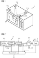
- Fig. 1 illustrates a schematic diagram of a microwave device 1.
- the microwave device 1 may be a microwave oven for heating food.
- the microwave device 1 comprises a cavity 2.
- Microwaves can be generated within the cavity 2 by means of microwave modules, wherein each microwave module corresponds to one microwave channel CH1 - CH4.
- the microwave device 1 comprises four microwave channels and therefore also four microwave modules.
- said number of microwave modules is only a mere example and the invention should not be considered limited to such number of microwave modules.
- the microwave device 1 may comprise two or more microwave modules.
- the microwave device 1 may be of solid-state type, i.e. the microwave channels are adapted to change the frequency of provided microwaves in order to vary the energy pattern inside the cavity 2. Said change of frequency leads to variations of the standing wave generated within the cavity 2 and thereby a more uniform energy spread inside the cavity 2 and therefore also inside the load to be heated by microwaves.
- Fig. 2 shows an example embodiment of a microwave module 3, which is coupled with an antenna which provides the microwaves generated by the microwave module 3 into the cavity 2.
- the microwave module 3 together with the antenna or waveguide may form a single microwave channel CH1 - CH4.
- the microwave module 3 comprises a control unit 3.1 adapted to control the generation of microwaves.
- the control unit 3.1 may, for example, include a microcontroller. More in detail, the control unit 3.1 may be adapted to influence the frequency, phase and amplitude of the microwave provided into the cavity 2.
- the microwave module 3 may comprise a voltage controlled oscillator (VCO) 3.2 which may comprise a phase locked loop (PLL) and an attenuator for generating a HF-signal with a certain frequency, phase and amplitude.
- VCO voltage controlled oscillator
- PLL phase locked loop
- the microwave generator 3 may comprise an amplifier 3.3 in order to adapt the electric power of the HF-signal.
- the control unit 3.1 may be operatively coupled with the voltage controlled oscillator (VCO) 3.2 and the amplifier 3.3 in order to generate an HF-signal with a certain frequency, phase and amplitude as desired.
- the control unit 3.1 may be configured to receive a set of operating parameters and generate an HF-signal according to said received operating parameters.
- Said set of operating parameters may comprise, for example, frequency information, phase information, amplitude or amplification information and/or ON/OFF-status information.
- Said frequency information is indicative for the frequency of the microwave signal.
- Said phase information may be indicative for the phase of the microwave signal (for example a phase relative to the microwave signal of another microwave channel).
- Said amplitude or amplification information may be indicative for the amplitude of the microwave signal or the amplification factor used within the microwave module.
- Said ON/OFF-status information may indicate whether the respective microwave channel should be turned on or turned off.
- the output of the amplifier 3.3 may be monitored by a monitoring entity 3.4. More in detail, the monitoring entity 3.4 may comprise a feedback loop which provides a portion of the output signal of the amplifier 3.3 back to the control unit 3.1 or another control entity in order to check whether the output of the amplifier 3.3 fulfils given requirements.
- the output of the amplifier 3.3 may further be coupled with a circulator 3.5.
- the circulator 3.5 may be adapted to forward the HF-signal provided by the amplifier 3.3 towards an antenna (not explicitly shown in Fig. 2 ) included in the cavity 2.
- the circulator 3.5 is adapted to filter out a reflected HF signal which is provided by the antenna backwards into the microwave module 3.
- "Filtering out” in the present case means that the reflected HF signal is blocked from traveling towards the amplifier 3.3 but is directed towards an electrical load 3.6 and/or a measurement system for measuring the reflected power.
- Said electrical load 3.6 is adapted to consume/absorb the reflected HF signal.
- Said electrical load 3.6 may be coupled with the control unit 3.1 in order to monitor the consumed/absorbed electric power of the reflected HF signal.
- Fig. 3 shows a schematic diagram of the microwave device 1 comprising four microwave modules 3, respectively, four microwave channels CH1 - CH4.
- Each microwave channel CH1 - CH4 includes a microwave module 3 as described before in connection with fig. 2 .
- each microwave module 3 is coupled with an antenna 4 provided inside the cavity 2.
- the microwave device 1 further comprises a master control entity 5 which is adapted to control the microwave channels CH1 - CH4, specifically the microwave modules 3 of the respective microwave channels CH1 - CH4, as further described below.
- Each microwave module 3 may be associated with a set of operating parameters which can be chosen in order to achieve a certain microwave transmission behaviour.
- the frequency of microwaves provided by the microwave generator 3 can be chosen in a certain range, e.g. in the range of 2.4 GHz to 2.5 GHz.
- the step width may be 100kHz or any other step width.
- all microwave channels CH1 - CH4 are operated at the same frequency, i.e. if the microwave frequency is changed, all channels change their frequency.
- phase of microwave provided by the microwave channels CH1 - CH4 can be varied.
- one channel may form the reference channel and a phase difference may be chosen between the reference channel and the other microwave channels.
- the phase difference may be selected in the range of 0° and 359°.
- the step width of phase difference may be 1° or any other step width.
- the electrical power of the microwave provided by the respective microwave channel CH1 - CH4 may be a further parameter to be selected.
- the electrical power may be chosen in the range between 0% and 100%, wherein 0% is power off and 100% is maximum power.
- the step width of electrical power may be 1% or any other step width.
- a further parameter may be microwave channel ON/OFF status.
- the set of operating parameters associated with a certain microwave module can not be chosen independent of the sets of operating parameters associated with the other microwave modules because said chosen set of operating parameters of one microwave module interacts with the other microwave modules.
- the sets of operating parameters have to match to each other in order to fulfil certain requirements.
- a first requirement may be that the channel reverse power (electric power received at a certain antenna of a microwave channel and coupled back into the microwave module) is below a certain threshold value in order to avoid any damage at the microwave module.
- a further requirement may be that the total reverse power (i.e. the sum of all channel reverse powers) is below a certain threshold value.
- microwave channel In order to obtain a uniform heating within the cavity 2 without hot and cold spots, the operating parameters corresponding to a certain microwave module 3, respectively, microwave channel may be changed frequently.
- Each intermediate state is characterized that a first set of microwave channels have already changed their operating parameters whereas another set of microwave channels have not changed their operating parameters.
- non-reliable intermediate states can occur in which the fulfilment of requirements can not guaranteed even if the start state (sets of operating parameters used by the microwave modules before change) and end state (sets of operating parameters used by the microwave modules after all changes) fulfil the requirements.
- the general idea is to obtain a synchronized change of operation parameters.
- a synchronized change of operation parameters at the respective microwave module 3 is obtained by a simultaneous transmission of the sets of operation parameters to the respective microwave modules 3.
- "Simultaneous transmission” means that the sets of operation parameters are not transmitted sequentially one after another but are transmitted concurrently. Thereby, the sets of operation parameters are received at the respective microwave modules 3 in a synchronous or quasi-synchronous way.
- the microwave modules 3 may be configured to immediately apply the set of parameters after receipt. Thereby a change of operation parameters at multiple microwave modules 3 is obtained with no or essentially no time delay and therefore a reduced risk of intermediate transition states.
- the change of parameters may occur after a certain time delay after the reception of the new parameters so to achieve time synchronization i.e. using the clock for the microwave generation.
- the change of operation parameters at the respective microwave modules is obtained by uploading the sets of operation parameters to the respective microwave modules. Said uploading may be obtained sequentially.
- the uploaded sets of operation parameters may be buffered within the respective microwave module 3.
- an acknowledge command is provided to the microwave modules 3, said acknowledge command triggering the application of said operation parameters at the respective microwave module 3. So in other words, the change of operation parameters will be executed only after receiving the acknowledge command as trigger information.
- the provision of the acknowledge command may be initiated by the master control entity 5.
- a data transmission line coupled to all microwave modules 3 may be used.
- the acknowledge command will reach the microwave modules simultaneously or quasi-simultaneously (e.g. with a time delay lower than 10ms, preferably lower than 5ms).
- the set of parameters buffered in a storage of the microwave module 3 may be applied.
- the transmission of the acknowledge command may be performed via a data bus or any other data connection between the microwave modules 3.
- the acknowledge command may be, for example, a binary word which is interpreted by the respective microwave modules 3 and triggers the take-over of a new set of operation parameters.
- a synchronization line or trigger line may be used for transmitting the acknowledge command.
- the acknowledge command may be, for example, a change of voltage level on said line.
- the amplification of the microwave modules may be lowered in order to reduce the transmission power during the parameter change period.
- Fig. 4 shows an exemplary flow diagram illustrating the steps performed during parameter change period.
- the take-over routine of new sets of operating parameters at the respective microwave modules may be controlled by a master control entity 5 (cf. Fig. 3 ).
- the master control entity 5 may be coupled with the microwave modules 3 via a data transmission line.
- the master control entity 5 may initiate the transmission of multiple sets of operation parameters to the microwave modules 3, wherein each set is sent to a certain microwave module 3 (S10).
- the transmission of operation parameters may be performed sequentially or at least partially in parallel.
- the master control entity 5 may transmit the sets of operation parameters to target microwave modules in order to assign a certain set to a certain microwave module 3.
- the microwave module 3 may take-over the operation parameters in a buffer. Thereby, the microwave module 3 is ready for applying the new set of operation parameters
- the master control entity 5 transmits an acknowledge command to the microwave modules 3, as already explained before (S11). The receipt of said acknowledge command initiates the take over of operation parameters.
- the microwave modules 3 may optionally decrease transmission power (S12). For example, transmission power may be reduced to a certain percentage value, e.g. 10% of target transmission power. Said decrease is obtained by lowering the amplification factor within the microwave module 3. The decrease of transmission power may be triggered by the acknowledge command itself or by a separate trigger for decreasing transmission power.
- the change of operation parameters is carried out (S13). So, the respective microwave modules change from previously used operation parameters (e.g. a certain frequency, phase constellation) to new operation parameters.
- previously used operation parameters e.g. a certain frequency, phase constellation
- the microwave modules 3 are driven based on the new sets of operation parameters and the transmission power may optionally increased to a target transmission power (S14).
- Said target transmission power may be indicated by a power value or amplification factor value included in the set of operation parameters.
- one or more massages can be provided from the respective microwave module 3 to the master control entity 5.
- Said messages may be set according to a handshaking procedure. For example, after reducing the transmission power, a message may be sent from each microwave module 3 to the master control entity 5 to confirm that the microwave module 3 is ready for operation parameter update.
- the master control entity 5 may send the acknowledge command to the microwave modules 3 only if all microwave modules 3 have confirmed readiness. Thereby, the master control entity 5 is informed about the procedures currently performed by the respective microwave module 3.
- the microwave modules 3 perform a measurement regarding channel reverse power.
- Said measurement may be performed during operating the microwave module 3 with the new set of operation parameters.
- Said channel reverse power may be the power coupling back into the microwave module 3 due to electromagnetic waves received at the antenna of the microwave module 3.
- the microwave module 3 may transmit information regarding the channel reverse power to the master control entity 5.
- the master control entity 5 is able to check whether the channel reverse power of all microwave modules 3 is below a threshold value and therefore the new set of operating parameters can be also used at nominal transmission power (increased transmission power). If all microwave modules 3 show channel reverse power below threshold value, the master control entity 5 can initiate the increase of transmission power to nominal/target transmission power. However, if channel reverse power of one or more microwave modules 3 exceeds the threshold value, the new set of operating parameters cannot be used at nominal/target transmission power and the master control entity 5 has to initiate the transmission of further sets of operating parameters to the microwave modules 3.
Landscapes
- Physics & Mathematics (AREA)
- Electromagnetism (AREA)
- Constitution Of High-Frequency Heating (AREA)
- Control Of High-Frequency Heating Circuits (AREA)
- Transmitters (AREA)
Abstract
Description
- The present invention relates generally to the field of microwave devices. More specifically, the present invention relates to a method for updating operating parameters of multiple microwave modules.
- Microwave devices, specifically microwave ovens, are well-known in prior art. Microwaves used in microwave ovens to heat food have, typically, a frequency of 2.45GHz. 900MHz is an alternative frequency used for heating food. The electromagnetic waves produce oscillating magnetic and electric fields that excite water molecules in food, therefore generating heat.
- For generating microwave frequency radiation, in a conventional microwave oven, high-voltage is applied to a magnetron. The microwaves are then transmitted through a waveguide to an enclosed cavity containing the load to be heated. The magnetron generates standing wave inside the cavity. Due to the fixed oscillation frequency, typically at 2.45GHz, the energy pattern inside the microwave oven is fixed. Thus, poor cooking results are achieved because the standing wave leads to so called "hot and cold spots" inside the cavity. To overcome this issue and have more evenness in cooking process, microwave ovens includes additional solutions such as a microwave stirrer and rotating plate.
- Microwave ovens using solid state technology introduce the capability to change oscillation frequency and so to vary standing wave and energy pattern inside the cavity. The usage of several microwave channels or microwave modules to direct energy into the cavity through launching devices (antennas, waveguide adapters etc.) enables further control capability. The relative phase changes between active channels lead to standing wave variations so to have different node and antinode configurations and a more uniform energy spread inside the cavity and also within the food. In order to obtain said uniform energy spread, the operating parameters of microwave modules have to be changed from time to time.
- Disadvantageously, when changing the operating parameters of multiple microwave modules, undefined intermediate states may occur which lead to critical operating conditions.
- It is an objective of the embodiments of the invention to provide a method for operating a microwave device comprising multiple microwave modules which ensures a safe change of operating parameters reducing the risk of critical operating conditions due to undesired intermediate states. The objective is solved by the features of the independent claims. Preferred embodiments are given in the dependent claims. If not explicitly indicated otherwise, embodiments of the invention can be freely combined with each other.
- According to an aspect, the invention refers to a method for operating a microwave device. The microwave device comprises a cavity and multiple microwave modules for providing microwaves into said cavity. The method comprises the steps of:
- providing multiple sets of operation parameters, each set of operation parameters being associated with a certain microwave module;
- ∘ simultaneously transmitting the sets of operation parameters to the respective microwave modules and synchronously applying the set of operation parameters within the respective microwave module after receipt of said set of operation parameters;
- ∘ uploading the sets of operation parameters to the respective microwave modules and applying the set of parameters within the respective microwave module after receipt of an acknowledge command or after expiry of a certain time period (e.g. a certain number of clock oscillations).
- Said method is advantageous because the take-over of operating parameters by the respective microwave modules can be synchronized or essentially synchronized leading to a reduction of undefined intermediate states.
- Those operations provide the technical advantage that the transition (in which the modules are not aligned with the desired working point) is minimal and so undefined states are avoid or minimized in which one module is working with the previous parameter and other modules are working with the new parameters or vice versa. This situation may lead to a disruptive effect on the microwave modules (channels) or an overstress due to the energy that flow back in the microwave modules in the non-verified state potentially out of the "safe operation area"
- Another advantage of avoiding or minimizing the transition states is the repeatability of cooking process due to the fact that the modules are working in the wanted condition and delivering the wanted amount of energy with the desired energy profile in the cavity.
- According to an embodiment, the set of operation parameters comprise frequency information, phase information, amplitude or amplification information and/or ON/OFF-status information.
- According to an embodiment, said uploading of sets of operation parameters to the respective microwave modules is performed in a sequential way. In other words, the operation parameters are uploaded to the microwave modules one after another. Thereby, for example a serial communication line or a data bus can be used for said upload operation.
- According to an embodiment, the uploaded sets of operation parameters are buffered within the respective microwave module. Thereby the operation parameters can be stored in the microwave module as long as a command is received for applying said operation parameters.
- According to an embodiment, the acknowledge command is transmitted via serial communication channel or data bus. Thus the acknowledge command may be, for example, a binary word which is specifically reserved for synchronization purposes.
- According to an embodiment, the acknowledge command is transmitted via a trigger line or synchronization line reserved for synchronization purposes. For example, the trigger line or synchronization line may be a dedicated line reserved for transmitting acknowledge commands or other synchronization information. Said acknowledge command may be, for example, a change of voltage applied to the trigger line or synchronization line. Thereby, a high synchronization of parameter change is obtained.
- According to an embodiment, the acknowledge command initiates a take-over-routine within two or more microwave modules, wherein an uploaded set of operation parameters is applied within a microwave module.
- According to an embodiment, transmission power of the microwave modules is reduced before applying the set of operation parameters and transmission power of the microwave modules is increased after applying the set of operation parameters. Thereby, a safe parameter change can be obtained.
- According to an embodiment, the microwave device comprises a master control entity and said master control entity receives information from one or more microwave modules, said information indicating that the microwave modules are ready for taking over the sets of operation parameters. Thereby, the receipt of operating parameters by the respective microwave modules and preferably also the reduction of transmission power can be monitored by the master control entity.
- According to an embodiment, after applying the sets of operation parameters, the microwave modules monitor the channel reverse power at a reduced power level. Thereby it is possible to determine whether the new sets of operating parameters lead to safe operating conditions of the microwave device.
- According to an embodiment, information regarding the channel reverse power is transmitted towards a master control entity. Thereby the master control entity is able to monitor the channel reverse power of all microwave modules and can decide whether safe operating conditions (channel revers power below a certain threshold; total revers power (sum of all channel revers powers) below a certain threshold value) are obtained when using the new sets of operating parameters. The decision may be made based on a mathematical model or any other decision scheme.
- According to an embodiment, the master control entity evaluates information regarding the channel reverse power from different microwave modules and initiates an increase of output power of the respective microwave modules to target output power if said evaluated information indicates that channel reverse powers of the microwave modules are below a certain threshold value. Thereby, the master control entity is able to control the increase of transmission power of the microwave device to nominal power.
- According to another embodiment, the master control unit may directly apply sets of operation parameters which are known to fulfil given operation conditions without decreasing power and parameter evaluation.
- According to an embodiment, the master control unit initiates the transmission of further sets of operation parameters to the microwave modules if evaluated information indicates that at least one channel reverse power is above a certain threshold value. Thereby, a set of operating parameters can be rejected if unsafe operating conditions occur.
- According to a further aspect, the invention relates to a microwave device. The microwave device comprises a cavity and multiple microwave modules for providing microwaves into said cavity. The microwave device further comprises a control entity configured to perform the following steps:
- providing multiple sets of operation parameters, each set of operation parameters being associated with a certain microwave module;
- ∘ simultaneously transmitting the sets of operation parameters to the respective microwave modules and synchronously(e.g. after expiry of a certain time period or a certain number of clock oscillations) applying the set of parameters within the respective microwave module after receipt of said set of parameters;
- ∘ uploading the sets of operation parameters to the respective microwave modules and applying the set of parameters within the respective microwave module after receipt of an acknowledge command or after expiry of a certain time period (e.g. a certain number of clock oscillations).
- The term "set of operation parameters" may refer to a set comprising a single operation parameter or multiple operation parameters.
- The term "essentially" or "approximately" as used in the invention means deviations from the exact value by +/- 10%, preferably by +/- 5% and/or deviations in the form of changes that are insignificant for the function.
- The various aspects of the invention, including its particular features and advantages, will be readily understood from the following detailed description and the accompanying drawings, in which:
- Fig. 1
- shows an example embodiment of a microwave device of solid-state type with multiple microwave channels;
- Fig. 2
- shows an example implementation of a microwave channel;
- Fig. 3
- shows a block diagram of a microwave device comprising multiple microwave channels; and
- Fig. 4
- shows a block diagram illustrating method steps performed during updating operation parameters of multiple microwave modules of a microwave device.
- The present invention will now be described more fully with reference to the accompanying drawings, in which example embodiments are shown. However, this invention should not be construed as limited to the embodiments set forth herein. Throughout the following description similar reference numerals have been used to denote similar elements, parts, items or features, when applicable.
-
Fig. 1 illustrates a schematic diagram of amicrowave device 1. Themicrowave device 1 may be a microwave oven for heating food. Themicrowave device 1 comprises acavity 2. Microwaves can be generated within thecavity 2 by means of microwave modules, wherein each microwave module corresponds to one microwave channel CH1 - CH4. In the present embodiment, themicrowave device 1 comprises four microwave channels and therefore also four microwave modules. However, said number of microwave modules is only a mere example and the invention should not be considered limited to such number of microwave modules. More generally, themicrowave device 1 may comprise two or more microwave modules. As already mentioned before, themicrowave device 1 may be of solid-state type, i.e. the microwave channels are adapted to change the frequency of provided microwaves in order to vary the energy pattern inside thecavity 2. Said change of frequency leads to variations of the standing wave generated within thecavity 2 and thereby a more uniform energy spread inside thecavity 2 and therefore also inside the load to be heated by microwaves. -
Fig. 2 shows an example embodiment of amicrowave module 3, which is coupled with an antenna which provides the microwaves generated by themicrowave module 3 into thecavity 2. Themicrowave module 3 together with the antenna or waveguide may form a single microwave channel CH1 - CH4. - The
microwave module 3 comprises a control unit 3.1 adapted to control the generation of microwaves. The control unit 3.1 may, for example, include a microcontroller. More in detail, the control unit 3.1 may be adapted to influence the frequency, phase and amplitude of the microwave provided into thecavity 2. For example, themicrowave module 3 may comprise a voltage controlled oscillator (VCO) 3.2 which may comprise a phase locked loop (PLL) and an attenuator for generating a HF-signal with a certain frequency, phase and amplitude. In addition, themicrowave generator 3 may comprise an amplifier 3.3 in order to adapt the electric power of the HF-signal. - The control unit 3.1 may be operatively coupled with the voltage controlled oscillator (VCO) 3.2 and the amplifier 3.3 in order to generate an HF-signal with a certain frequency, phase and amplitude as desired. The control unit 3.1 may be configured to receive a set of operating parameters and generate an HF-signal according to said received operating parameters. Said set of operating parameters may comprise, for example, frequency information, phase information, amplitude or amplification information and/or ON/OFF-status information. Said frequency information is indicative for the frequency of the microwave signal. Said phase information may be indicative for the phase of the microwave signal (for example a phase relative to the microwave signal of another microwave channel). Said amplitude or amplification information may be indicative for the amplitude of the microwave signal or the amplification factor used within the microwave module. Said ON/OFF-status information may indicate whether the respective microwave channel should be turned on or turned off.
- The output of the amplifier 3.3 may be monitored by a monitoring entity 3.4. More in detail, the monitoring entity 3.4 may comprise a feedback loop which provides a portion of the output signal of the amplifier 3.3 back to the control unit 3.1 or another control entity in order to check whether the output of the amplifier 3.3 fulfils given requirements.
- The output of the amplifier 3.3 may further be coupled with a circulator 3.5. The circulator 3.5 may be adapted to forward the HF-signal provided by the amplifier 3.3 towards an antenna (not explicitly shown in
Fig. 2 ) included in thecavity 2. However, the circulator 3.5 is adapted to filter out a reflected HF signal which is provided by the antenna backwards into themicrowave module 3. "Filtering out" in the present case means that the reflected HF signal is blocked from traveling towards the amplifier 3.3 but is directed towards an electrical load 3.6 and/or a measurement system for measuring the reflected power. Said electrical load 3.6 is adapted to consume/absorb the reflected HF signal. Said electrical load 3.6 may be coupled with the control unit 3.1 in order to monitor the consumed/absorbed electric power of the reflected HF signal. -
Fig. 3 shows a schematic diagram of themicrowave device 1 comprising fourmicrowave modules 3, respectively, four microwave channels CH1 - CH4. Each microwave channel CH1 - CH4 includes amicrowave module 3 as described before in connection withfig. 2 . In addition, eachmicrowave module 3 is coupled with anantenna 4 provided inside thecavity 2. Themicrowave device 1 further comprises amaster control entity 5 which is adapted to control the microwave channels CH1 - CH4, specifically themicrowave modules 3 of the respective microwave channels CH1 - CH4, as further described below. - Each
microwave module 3 may be associated with a set of operating parameters which can be chosen in order to achieve a certain microwave transmission behaviour. For example, the frequency of microwaves provided by themicrowave generator 3 can be chosen in a certain range, e.g. in the range of 2.4 GHz to 2.5 GHz. The step width may be 100kHz or any other step width. Preferably, all microwave channels CH1 - CH4 are operated at the same frequency, i.e. if the microwave frequency is changed, all channels change their frequency. - In addition, the phase of microwave provided by the microwave channels CH1 - CH4 can be varied. For example, one channel may form the reference channel and a phase difference may be chosen between the reference channel and the other microwave channels. The phase difference may be selected in the range of 0° and 359°. The step width of phase difference may be 1° or any other step width.
- Furthermore, the electrical power of the microwave provided by the respective microwave channel CH1 - CH4 may be a further parameter to be selected. The electrical power may be chosen in the range between 0% and 100%, wherein 0% is power off and 100% is maximum power. The step width of electrical power may be 1% or any other step width.
- A further parameter may be microwave channel ON/OFF status.
- In order to fulfil certain requirements, the set of operating parameters associated with a certain microwave module can not be chosen independent of the sets of operating parameters associated with the other microwave modules because said chosen set of operating parameters of one microwave module interacts with the other microwave modules. In other words, the sets of operating parameters have to match to each other in order to fulfil certain requirements. A first requirement may be that the channel reverse power (electric power received at a certain antenna of a microwave channel and coupled back into the microwave module) is below a certain threshold value in order to avoid any damage at the microwave module. A further requirement may be that the total reverse power (i.e. the sum of all channel reverse powers) is below a certain threshold value.
- In order to obtain a uniform heating within the
cavity 2 without hot and cold spots, the operating parameters corresponding to acertain microwave module 3, respectively, microwave channel may be changed frequently. - When changing the sets of operating parameters in a
microwave device 1 comprising multiple microwave channels CH1 - CH4, a plurality of intermediate states may occur. Each intermediate state is characterized that a first set of microwave channels have already changed their operating parameters whereas another set of microwave channels have not changed their operating parameters. - When changing the operating parameters within the microwave modules, non-reliable intermediate states can occur in which the fulfilment of requirements can not guaranteed even if the start state (sets of operating parameters used by the microwave modules before change) and end state (sets of operating parameters used by the microwave modules after all changes) fulfil the requirements.
- In order to reduce the risks of any non-reliable intermediate states, a method for avoiding undesired transition states during change of operation parameters in the
microwave device 1 is disclosed. - The general idea is to obtain a synchronized change of operation parameters.
- According to a first embodiment, a synchronized change of operation parameters at the
respective microwave module 3 is obtained by a simultaneous transmission of the sets of operation parameters to therespective microwave modules 3. "Simultaneous transmission" means that the sets of operation parameters are not transmitted sequentially one after another but are transmitted concurrently. Thereby, the sets of operation parameters are received at therespective microwave modules 3 in a synchronous or quasi-synchronous way. In addition, themicrowave modules 3 may be configured to immediately apply the set of parameters after receipt. Thereby a change of operation parameters atmultiple microwave modules 3 is obtained with no or essentially no time delay and therefore a reduced risk of intermediate transition states. In another embodiment the change of parameters may occur after a certain time delay after the reception of the new parameters so to achieve time synchronization i.e. using the clock for the microwave generation. - According to a second embodiment, the change of operation parameters at the respective microwave modules is obtained by uploading the sets of operation parameters to the respective microwave modules. Said uploading may be obtained sequentially. The uploaded sets of operation parameters may be buffered within the
respective microwave module 3. After all operation parameters have been uploaded, an acknowledge command is provided to themicrowave modules 3, said acknowledge command triggering the application of said operation parameters at therespective microwave module 3. So in other words, the change of operation parameters will be executed only after receiving the acknowledge command as trigger information. The provision of the acknowledge command may be initiated by themaster control entity 5. - For transmitting the acknowledge command to the microwave modules, a data transmission line coupled to all
microwave modules 3 may be used. The acknowledge command will reach the microwave modules simultaneously or quasi-simultaneously (e.g. with a time delay lower than 10ms, preferably lower than 5ms). After receipt of said acknowledge command, the set of parameters buffered in a storage of themicrowave module 3 may be applied. - The transmission of the acknowledge command may be performed via a data bus or any other data connection between the
microwave modules 3. The acknowledge command may be, for example, a binary word which is interpreted by therespective microwave modules 3 and triggers the take-over of a new set of operation parameters. - According to other embodiments, a synchronization line or trigger line may be used for transmitting the acknowledge command. Using a synchronization line or trigger line, the acknowledge command may be, for example, a change of voltage level on said line. Thereby, the synchronization of taking over a new set of operation parameters can be further improved.
- In order to further increase the safety during change of operation parameters, the amplification of the microwave modules may be lowered in order to reduce the transmission power during the parameter change period.
-
Fig. 4 shows an exemplary flow diagram illustrating the steps performed during parameter change period. - The take-over routine of new sets of operating parameters at the respective microwave modules may be controlled by a master control entity 5 (cf.
Fig. 3 ). Themaster control entity 5 may be coupled with themicrowave modules 3 via a data transmission line. - In a first step, the
master control entity 5 may initiate the transmission of multiple sets of operation parameters to themicrowave modules 3, wherein each set is sent to a certain microwave module 3 (S10). The transmission of operation parameters may be performed sequentially or at least partially in parallel. For example, themaster control entity 5 may transmit the sets of operation parameters to target microwave modules in order to assign a certain set to acertain microwave module 3. - After receiving the set of operation parameters at the
microwave module 3, themicrowave module 3 may take-over the operation parameters in a buffer. Thereby, themicrowave module 3 is ready for applying the new set of operation parameters - After all sets of operation parameter have been received at the
respective microwave modules 3, themaster control entity 5 transmits an acknowledge command to themicrowave modules 3, as already explained before (S11). The receipt of said acknowledge command initiates the take over of operation parameters. - However, before taking over the operation parameters, the
microwave modules 3 may optionally decrease transmission power (S12). For example, transmission power may be reduced to a certain percentage value, e.g. 10% of target transmission power. Said decrease is obtained by lowering the amplification factor within themicrowave module 3. The decrease of transmission power may be triggered by the acknowledge command itself or by a separate trigger for decreasing transmission power. - After decreasing the transmission power, the change of operation parameters is carried out (S13). So, the respective microwave modules change from previously used operation parameters (e.g. a certain frequency, phase constellation) to new operation parameters.
- After changing the operation parameters, the
microwave modules 3 are driven based on the new sets of operation parameters and the transmission power may optionally increased to a target transmission power (S14). Said target transmission power may be indicated by a power value or amplification factor value included in the set of operation parameters. - During performing upper-mentioned steps of decreasing transmission power, taking over of operating parameters and increasing the transmission power, one or more massages can be provided from the
respective microwave module 3 to themaster control entity 5. Said messages may be set according to a handshaking procedure. For example, after reducing the transmission power, a message may be sent from eachmicrowave module 3 to themaster control entity 5 to confirm that themicrowave module 3 is ready for operation parameter update. Themaster control entity 5 may send the acknowledge command to themicrowave modules 3 only if allmicrowave modules 3 have confirmed readiness. Thereby, themaster control entity 5 is informed about the procedures currently performed by therespective microwave module 3. Preferably, during powering themicrowave modules 3 at reduced power level, themicrowave modules 3 perform a measurement regarding channel reverse power. Said measurement may be performed during operating themicrowave module 3 with the new set of operation parameters. Said channel reverse power may be the power coupling back into themicrowave module 3 due to electromagnetic waves received at the antenna of themicrowave module 3. Themicrowave module 3 may transmit information regarding the channel reverse power to themaster control entity 5. Thereby themaster control entity 5 is able to check whether the channel reverse power of allmicrowave modules 3 is below a threshold value and therefore the new set of operating parameters can be also used at nominal transmission power (increased transmission power). If allmicrowave modules 3 show channel reverse power below threshold value, themaster control entity 5 can initiate the increase of transmission power to nominal/target transmission power. However, if channel reverse power of one ormore microwave modules 3 exceeds the threshold value, the new set of operating parameters cannot be used at nominal/target transmission power and themaster control entity 5 has to initiate the transmission of further sets of operating parameters to themicrowave modules 3. - Thereby, safe operation using multiple different sets of operation parameters can be ensured.
- It should be noted that the description and drawings merely illustrate the principles of the proposed invention. Those skilled in the art will be able to implement various arrangements that, although not explicitly described or shown herein, embody the principles of the invention.
-
- 1
- microwave device
- 2
- cavity
- 3
- microwave module
- 3.1
- control unit
- 3.2
- voltage controlled oscillator
- 3.3
- amplifier
- 3.4
- monitoring entity
- 3.5
- circulator
- 3.6
- electrical load
- 4
- antenna
- 5
- master control entity
- CH1 - CH4
- microwave channel
- RP
- channel reverse power
Claims (14)
- Method for operating a microwave device (1), the microwave device (1) comprising a cavity (2) and multiple microwave modules (3) for providing microwaves into said cavity (2), the method comprising the steps of:- providing multiple sets of operation parameters, each set of operation parameters being associated with a certain microwave module (3);∘ synchronously transmitting the sets of operation parameters to the respective microwave modules (3) and immediately applying the set of operation parameters within the respective microwave module (3) after receipt of said set of operation parameters;or∘ uploading the sets of operation parameters to the respective microwave modules (3) and applying the set of parameters within the respective microwave module (3) after receipt of an acknowledge command or after expiry of a certain time period.
- Method according to claim 1, wherein the set of operation parameters comprise frequency information, phase information, amplitude or amplification information and/or ON/OFF-status information.
- Method according to claim 1 or 2, wherein uploading the sets of operation parameters to the respective microwave modules (3) is performed in a sequential way.
- Method according to anyone of the preceding claims, wherein the uploaded sets of operation parameters are buffered within the respective microwave module (3).
- Method according to anyone of the preceding claims, wherein the acknowledge command is transmitted via serial communication channel or data bus.
- Method according to anyone of the preceding claims, wherein the acknowledge command is transmitted via a trigger line or synchronization line reserved for synchronization purposes.
- Method according to anyone of the preceding claims, wherein the acknowledge command initiates a take-over-routine within two or more microwave modules (3), wherein an uploaded set of operation parameters is applied within a microwave module (3) .
- Method according to anyone of the preceding claims, wherein transmission power of the microwave modules (3) is reduced before applying the set of operation parameters and transmission power of the microwave modules (3) is increased after applying the set of operation parameters.
- Method according to anyone of the preceding claims, wherein the microwave device (1) comprises a master control entity (5) and said master control entity (5) receives information from one or more microwave modules (3), said information indicating that the microwave modules (3) are ready for taking over the sets of operation parameters.
- Method according to anyone of the preceding claims, wherein after applying the sets of operation parameters, the microwave modules (3) monitor the channel reverse power at a reduced power level.
- Method according to claim 10, wherein information regarding the channel reverse power is transmitted towards a master control entity (5).
- Method according to claim 11, wherein the master control entity (5) evaluates information regarding the channel reverse power from different microwave modules (3) and initiates an increase of output power of the respective microwave modules (3) to target output power if said evaluated information indicates that channel reverse power values of the microwave modules (3) are below a certain threshold value.
- Method according to claim 11 or 12, wherein the master control unit initiates the transmission of further sets of operation parameters to the microwave modules (3) if evaluated information indicates that at least one channel reverse power is above a certain threshold value.
- Microwave device comprising a cavity (2) and multiple microwave modules (3) for providing microwaves within said cavity (2), wherein the microwave device (1) comprises a control entity (5), the control entity (5) being configured to perform the following steps:- providing multiple sets of operation parameters, each set of operation parameters being associated with a certain microwave module (3);∘ simultaneously transmitting the sets of operation parameters to the respective microwave modules (3) and synchronously applying the set of parameters within the respective microwave module (3) after receipt of said set of parameters;or∘ uploading the sets of operation parameters to the respective microwave modules (3) and applying the set of parameters within the respective microwave module (3) after receipt of an acknowledge command or after expiry of a certain time period.
Priority Applications (5)
| Application Number | Priority Date | Filing Date | Title |
|---|---|---|---|
| EP18189160.7A EP3612005B1 (en) | 2018-08-15 | 2018-08-15 | Method for operating a microwave device |
| BR112021002425-5A BR112021002425A2 (en) | 2018-08-15 | 2019-07-17 | method for operating a microwave device |
| US17/268,368 US20210337639A1 (en) | 2018-08-15 | 2019-07-17 | Method for operating a microwave device |
| PCT/EP2019/069299 WO2020035251A1 (en) | 2018-08-15 | 2019-07-17 | Method for operating a microwave device |
| AU2019320981A AU2019320981A1 (en) | 2018-08-15 | 2019-07-17 | Method for operating a microwave device |
Applications Claiming Priority (1)
| Application Number | Priority Date | Filing Date | Title |
|---|---|---|---|
| EP18189160.7A EP3612005B1 (en) | 2018-08-15 | 2018-08-15 | Method for operating a microwave device |
Publications (2)
| Publication Number | Publication Date |
|---|---|
| EP3612005A1 true EP3612005A1 (en) | 2020-02-19 |
| EP3612005B1 EP3612005B1 (en) | 2022-06-29 |
Family
ID=63294002
Family Applications (1)
| Application Number | Title | Priority Date | Filing Date |
|---|---|---|---|
| EP18189160.7A Active EP3612005B1 (en) | 2018-08-15 | 2018-08-15 | Method for operating a microwave device |
Country Status (5)
| Country | Link |
|---|---|
| US (1) | US20210337639A1 (en) |
| EP (1) | EP3612005B1 (en) |
| AU (1) | AU2019320981A1 (en) |
| BR (1) | BR112021002425A2 (en) |
| WO (1) | WO2020035251A1 (en) |
Citations (4)
| Publication number | Priority date | Publication date | Assignee | Title |
|---|---|---|---|---|
| JP2009032638A (en) * | 2007-07-05 | 2009-02-12 | Panasonic Corp | Microwave processing device |
| EP2182774A1 (en) * | 2007-07-13 | 2010-05-05 | Panasonic Corporation | Microwave heating device |
| EP3000283A2 (en) * | 2013-05-21 | 2016-03-30 | Goji Limited | Calibration of an rf processing system |
| WO2018125182A1 (en) * | 2016-12-30 | 2018-07-05 | Whirlpool Corporation | Cost effective hybrid protection for high power amplifier. |
-
2018
- 2018-08-15 EP EP18189160.7A patent/EP3612005B1/en active Active
-
2019
- 2019-07-17 BR BR112021002425-5A patent/BR112021002425A2/en not_active Application Discontinuation
- 2019-07-17 WO PCT/EP2019/069299 patent/WO2020035251A1/en active Application Filing
- 2019-07-17 US US17/268,368 patent/US20210337639A1/en not_active Abandoned
- 2019-07-17 AU AU2019320981A patent/AU2019320981A1/en not_active Abandoned
Patent Citations (4)
| Publication number | Priority date | Publication date | Assignee | Title |
|---|---|---|---|---|
| JP2009032638A (en) * | 2007-07-05 | 2009-02-12 | Panasonic Corp | Microwave processing device |
| EP2182774A1 (en) * | 2007-07-13 | 2010-05-05 | Panasonic Corporation | Microwave heating device |
| EP3000283A2 (en) * | 2013-05-21 | 2016-03-30 | Goji Limited | Calibration of an rf processing system |
| WO2018125182A1 (en) * | 2016-12-30 | 2018-07-05 | Whirlpool Corporation | Cost effective hybrid protection for high power amplifier. |
Non-Patent Citations (1)
| Title |
|---|
| JOHN PARK, STEVE MACKAY, EDWIN WRIGHT: "Data Communications for Instrumentation and Control", REFEREX, 31 December 2003 (2003-12-31), XP040425386, ISBN: 0750657979 * |
Also Published As
| Publication number | Publication date |
|---|---|
| AU2019320981A1 (en) | 2021-01-21 |
| WO2020035251A1 (en) | 2020-02-20 |
| US20210337639A1 (en) | 2021-10-28 |
| EP3612005B1 (en) | 2022-06-29 |
| BR112021002425A2 (en) | 2021-05-04 |
Similar Documents
| Publication | Publication Date | Title |
|---|---|---|
| US9363854B2 (en) | Cooking apparatus using microwaves | |
| US5321222A (en) | Variable frequency microwave furnace system | |
| CN107249229B (en) | Microwave processing apparatus, method, and machine-readable storage medium | |
| US9307583B2 (en) | Cooking apparatus and operating method thereof | |
| KR101709473B1 (en) | A Cooking apparatus using microwave | |
| JP2008270112A (en) | Control method of high-frequency heating device | |
| CN109587861A (en) | A kind of multifrequency solid state microwave furnace and the heating means using multifrequency solid state microwave furnace | |
| EP3612005B1 (en) | Method for operating a microwave device | |
| CN112567888B (en) | Method for operating a microwave device | |
| EP3550936B1 (en) | Microwave heating system having improved frequency scanning and heating methods | |
| Obata et al. | State of the art advanced magnetrons for accelerator RF power source | |
| KR101759160B1 (en) | A cooking apparatus and method for operating the same | |
| CN112020164B (en) | Radio frequency heating circuit and radio frequency heating equipment | |
| KR101748608B1 (en) | A cooking apparatus using microwave | |
| US10470258B2 (en) | High frequency heating device | |
| EP3768045B1 (en) | Microwave oven | |
| JP2015125819A (en) | Microwave processing apparatus | |
| CN109548215B (en) | Microwave equipment | |
| KR101588839B1 (en) | A cooking apparatus using microwave | |
| CN111867174B (en) | Power control method of radio frequency heating module and radio frequency heating device | |
| KR102001299B1 (en) | Microwave oven and method for controlling the same | |
| KR101727905B1 (en) | A cooking apparatus using microwave and method for operating the same | |
| JP2016066464A (en) | Microwave output device | |
| KR101731389B1 (en) | A cooking apparatus using microwave | |
| KR101620447B1 (en) | A cooking apparatus using microwave |
Legal Events
| Date | Code | Title | Description |
|---|---|---|---|
| PUAI | Public reference made under article 153(3) epc to a published international application that has entered the european phase |
Free format text: ORIGINAL CODE: 0009012 |
|
| STAA | Information on the status of an ep patent application or granted ep patent |
Free format text: STATUS: THE APPLICATION HAS BEEN PUBLISHED |
|
| AK | Designated contracting states |
Kind code of ref document: A1 Designated state(s): AL AT BE BG CH CY CZ DE DK EE ES FI FR GB GR HR HU IE IS IT LI LT LU LV MC MK MT NL NO PL PT RO RS SE SI SK SM TR |
|
| AX | Request for extension of the european patent |
Extension state: BA ME |
|
| STAA | Information on the status of an ep patent application or granted ep patent |
Free format text: STATUS: REQUEST FOR EXAMINATION WAS MADE |
|
| 17P | Request for examination filed |
Effective date: 20200819 |
|
| RBV | Designated contracting states (corrected) |
Designated state(s): AL AT BE BG CH CY CZ DE DK EE ES FI FR GB GR HR HU IE IS IT LI LT LU LV MC MK MT NL NO PL PT RO RS SE SI SK SM TR |
|
| GRAP | Despatch of communication of intention to grant a patent |
Free format text: ORIGINAL CODE: EPIDOSNIGR1 |
|
| STAA | Information on the status of an ep patent application or granted ep patent |
Free format text: STATUS: GRANT OF PATENT IS INTENDED |
|
| INTG | Intention to grant announced |
Effective date: 20220214 |
|
| GRAS | Grant fee paid |
Free format text: ORIGINAL CODE: EPIDOSNIGR3 |
|
| GRAA | (expected) grant |
Free format text: ORIGINAL CODE: 0009210 |
|
| STAA | Information on the status of an ep patent application or granted ep patent |
Free format text: STATUS: THE PATENT HAS BEEN GRANTED |
|
| AK | Designated contracting states |
Kind code of ref document: B1 Designated state(s): AL AT BE BG CH CY CZ DE DK EE ES FI FR GB GR HR HU IE IS IT LI LT LU LV MC MK MT NL NO PL PT RO RS SE SI SK SM TR |
|
| REG | Reference to a national code |
Ref country code: CH Ref legal event code: EP |
|
| REG | Reference to a national code |
Ref country code: AT Ref legal event code: REF Ref document number: 1502151 Country of ref document: AT Kind code of ref document: T Effective date: 20220715 |
|
| REG | Reference to a national code |
Ref country code: IE Ref legal event code: FG4D |
|
| REG | Reference to a national code |
Ref country code: DE Ref legal event code: R096 Ref document number: 602018037232 Country of ref document: DE |
|
| REG | Reference to a national code |
Ref country code: LT Ref legal event code: MG9D |
|
| PG25 | Lapsed in a contracting state [announced via postgrant information from national office to epo] |
Ref country code: SE Free format text: LAPSE BECAUSE OF FAILURE TO SUBMIT A TRANSLATION OF THE DESCRIPTION OR TO PAY THE FEE WITHIN THE PRESCRIBED TIME-LIMIT Effective date: 20220629 Ref country code: NO Free format text: LAPSE BECAUSE OF FAILURE TO SUBMIT A TRANSLATION OF THE DESCRIPTION OR TO PAY THE FEE WITHIN THE PRESCRIBED TIME-LIMIT Effective date: 20220929 Ref country code: LT Free format text: LAPSE BECAUSE OF FAILURE TO SUBMIT A TRANSLATION OF THE DESCRIPTION OR TO PAY THE FEE WITHIN THE PRESCRIBED TIME-LIMIT Effective date: 20220629 Ref country code: HR Free format text: LAPSE BECAUSE OF FAILURE TO SUBMIT A TRANSLATION OF THE DESCRIPTION OR TO PAY THE FEE WITHIN THE PRESCRIBED TIME-LIMIT Effective date: 20220629 Ref country code: GR Free format text: LAPSE BECAUSE OF FAILURE TO SUBMIT A TRANSLATION OF THE DESCRIPTION OR TO PAY THE FEE WITHIN THE PRESCRIBED TIME-LIMIT Effective date: 20220930 Ref country code: FI Free format text: LAPSE BECAUSE OF FAILURE TO SUBMIT A TRANSLATION OF THE DESCRIPTION OR TO PAY THE FEE WITHIN THE PRESCRIBED TIME-LIMIT Effective date: 20220629 Ref country code: BG Free format text: LAPSE BECAUSE OF FAILURE TO SUBMIT A TRANSLATION OF THE DESCRIPTION OR TO PAY THE FEE WITHIN THE PRESCRIBED TIME-LIMIT Effective date: 20220929 |
|
| PGFP | Annual fee paid to national office [announced via postgrant information from national office to epo] |
Ref country code: DE Payment date: 20220830 Year of fee payment: 5 |
|
| REG | Reference to a national code |
Ref country code: NL Ref legal event code: MP Effective date: 20220629 |
|
| REG | Reference to a national code |
Ref country code: AT Ref legal event code: MK05 Ref document number: 1502151 Country of ref document: AT Kind code of ref document: T Effective date: 20220629 |
|
| PG25 | Lapsed in a contracting state [announced via postgrant information from national office to epo] |
Ref country code: RS Free format text: LAPSE BECAUSE OF FAILURE TO SUBMIT A TRANSLATION OF THE DESCRIPTION OR TO PAY THE FEE WITHIN THE PRESCRIBED TIME-LIMIT Effective date: 20220629 Ref country code: LV Free format text: LAPSE BECAUSE OF FAILURE TO SUBMIT A TRANSLATION OF THE DESCRIPTION OR TO PAY THE FEE WITHIN THE PRESCRIBED TIME-LIMIT Effective date: 20220629 |
|
| PG25 | Lapsed in a contracting state [announced via postgrant information from national office to epo] |
Ref country code: NL Free format text: LAPSE BECAUSE OF FAILURE TO SUBMIT A TRANSLATION OF THE DESCRIPTION OR TO PAY THE FEE WITHIN THE PRESCRIBED TIME-LIMIT Effective date: 20220629 |
|
| PG25 | Lapsed in a contracting state [announced via postgrant information from national office to epo] |
Ref country code: SM Free format text: LAPSE BECAUSE OF FAILURE TO SUBMIT A TRANSLATION OF THE DESCRIPTION OR TO PAY THE FEE WITHIN THE PRESCRIBED TIME-LIMIT Effective date: 20220629 Ref country code: SK Free format text: LAPSE BECAUSE OF FAILURE TO SUBMIT A TRANSLATION OF THE DESCRIPTION OR TO PAY THE FEE WITHIN THE PRESCRIBED TIME-LIMIT Effective date: 20220629 Ref country code: RO Free format text: LAPSE BECAUSE OF FAILURE TO SUBMIT A TRANSLATION OF THE DESCRIPTION OR TO PAY THE FEE WITHIN THE PRESCRIBED TIME-LIMIT Effective date: 20220629 Ref country code: PT Free format text: LAPSE BECAUSE OF FAILURE TO SUBMIT A TRANSLATION OF THE DESCRIPTION OR TO PAY THE FEE WITHIN THE PRESCRIBED TIME-LIMIT Effective date: 20221031 Ref country code: ES Free format text: LAPSE BECAUSE OF FAILURE TO SUBMIT A TRANSLATION OF THE DESCRIPTION OR TO PAY THE FEE WITHIN THE PRESCRIBED TIME-LIMIT Effective date: 20220629 Ref country code: EE Free format text: LAPSE BECAUSE OF FAILURE TO SUBMIT A TRANSLATION OF THE DESCRIPTION OR TO PAY THE FEE WITHIN THE PRESCRIBED TIME-LIMIT Effective date: 20220629 Ref country code: AT Free format text: LAPSE BECAUSE OF FAILURE TO SUBMIT A TRANSLATION OF THE DESCRIPTION OR TO PAY THE FEE WITHIN THE PRESCRIBED TIME-LIMIT Effective date: 20220629 |
|
| PGFP | Annual fee paid to national office [announced via postgrant information from national office to epo] |
Ref country code: IT Payment date: 20220929 Year of fee payment: 5 |
|
| PG25 | Lapsed in a contracting state [announced via postgrant information from national office to epo] |
Ref country code: PL Free format text: LAPSE BECAUSE OF FAILURE TO SUBMIT A TRANSLATION OF THE DESCRIPTION OR TO PAY THE FEE WITHIN THE PRESCRIBED TIME-LIMIT Effective date: 20220629 Ref country code: IS Free format text: LAPSE BECAUSE OF FAILURE TO SUBMIT A TRANSLATION OF THE DESCRIPTION OR TO PAY THE FEE WITHIN THE PRESCRIBED TIME-LIMIT Effective date: 20221029 |
|
| REG | Reference to a national code |
Ref country code: DE Ref legal event code: R097 Ref document number: 602018037232 Country of ref document: DE |
|
| PG25 | Lapsed in a contracting state [announced via postgrant information from national office to epo] |
Ref country code: MC Free format text: LAPSE BECAUSE OF FAILURE TO SUBMIT A TRANSLATION OF THE DESCRIPTION OR TO PAY THE FEE WITHIN THE PRESCRIBED TIME-LIMIT Effective date: 20220629 Ref country code: AL Free format text: LAPSE BECAUSE OF FAILURE TO SUBMIT A TRANSLATION OF THE DESCRIPTION OR TO PAY THE FEE WITHIN THE PRESCRIBED TIME-LIMIT Effective date: 20220629 |
|
| REG | Reference to a national code |
Ref country code: CH Ref legal event code: PL |
|
| PG25 | Lapsed in a contracting state [announced via postgrant information from national office to epo] |
Ref country code: LU Free format text: LAPSE BECAUSE OF NON-PAYMENT OF DUE FEES Effective date: 20220815 Ref country code: LI Free format text: LAPSE BECAUSE OF NON-PAYMENT OF DUE FEES Effective date: 20220831 Ref country code: DK Free format text: LAPSE BECAUSE OF FAILURE TO SUBMIT A TRANSLATION OF THE DESCRIPTION OR TO PAY THE FEE WITHIN THE PRESCRIBED TIME-LIMIT Effective date: 20220629 Ref country code: CZ Free format text: LAPSE BECAUSE OF FAILURE TO SUBMIT A TRANSLATION OF THE DESCRIPTION OR TO PAY THE FEE WITHIN THE PRESCRIBED TIME-LIMIT Effective date: 20220629 Ref country code: CH Free format text: LAPSE BECAUSE OF NON-PAYMENT OF DUE FEES Effective date: 20220831 |
|
| REG | Reference to a national code |
Ref country code: BE Ref legal event code: MM Effective date: 20220831 |
|
| PLBE | No opposition filed within time limit |
Free format text: ORIGINAL CODE: 0009261 |
|
| STAA | Information on the status of an ep patent application or granted ep patent |
Free format text: STATUS: NO OPPOSITION FILED WITHIN TIME LIMIT |
|
| GBPC | Gb: european patent ceased through non-payment of renewal fee |
Effective date: 20220929 |
|
| 26N | No opposition filed |
Effective date: 20230330 |
|
| PG25 | Lapsed in a contracting state [announced via postgrant information from national office to epo] |
Ref country code: IE Free format text: LAPSE BECAUSE OF NON-PAYMENT OF DUE FEES Effective date: 20220815 Ref country code: FR Free format text: LAPSE BECAUSE OF NON-PAYMENT OF DUE FEES Effective date: 20220829 |
|
| P01 | Opt-out of the competence of the unified patent court (upc) registered |
Effective date: 20230625 |
|
| PG25 | Lapsed in a contracting state [announced via postgrant information from national office to epo] |
Ref country code: SI Free format text: LAPSE BECAUSE OF FAILURE TO SUBMIT A TRANSLATION OF THE DESCRIPTION OR TO PAY THE FEE WITHIN THE PRESCRIBED TIME-LIMIT Effective date: 20220629 |
|
| PG25 | Lapsed in a contracting state [announced via postgrant information from national office to epo] |
Ref country code: BE Free format text: LAPSE BECAUSE OF NON-PAYMENT OF DUE FEES Effective date: 20220831 |
|
| PG25 | Lapsed in a contracting state [announced via postgrant information from national office to epo] |
Ref country code: GB Free format text: LAPSE BECAUSE OF NON-PAYMENT OF DUE FEES Effective date: 20220929 |
|
| REG | Reference to a national code |
Ref country code: DE Ref legal event code: R119 Ref document number: 602018037232 Country of ref document: DE |
|
| PG25 | Lapsed in a contracting state [announced via postgrant information from national office to epo] |
Ref country code: HU Free format text: LAPSE BECAUSE OF FAILURE TO SUBMIT A TRANSLATION OF THE DESCRIPTION OR TO PAY THE FEE WITHIN THE PRESCRIBED TIME-LIMIT; INVALID AB INITIO Effective date: 20180815 |
|
| PG25 | Lapsed in a contracting state [announced via postgrant information from national office to epo] |
Ref country code: CY Free format text: LAPSE BECAUSE OF FAILURE TO SUBMIT A TRANSLATION OF THE DESCRIPTION OR TO PAY THE FEE WITHIN THE PRESCRIBED TIME-LIMIT Effective date: 20220629 |
|
| PG25 | Lapsed in a contracting state [announced via postgrant information from national office to epo] |
Ref country code: MK Free format text: LAPSE BECAUSE OF FAILURE TO SUBMIT A TRANSLATION OF THE DESCRIPTION OR TO PAY THE FEE WITHIN THE PRESCRIBED TIME-LIMIT Effective date: 20220629 |
|
| PG25 | Lapsed in a contracting state [announced via postgrant information from national office to epo] |
Ref country code: TR Free format text: LAPSE BECAUSE OF FAILURE TO SUBMIT A TRANSLATION OF THE DESCRIPTION OR TO PAY THE FEE WITHIN THE PRESCRIBED TIME-LIMIT Effective date: 20220629 |
|
| PG25 | Lapsed in a contracting state [announced via postgrant information from national office to epo] |
Ref country code: IT Free format text: LAPSE BECAUSE OF NON-PAYMENT OF DUE FEES Effective date: 20230815 Ref country code: DE Free format text: LAPSE BECAUSE OF NON-PAYMENT OF DUE FEES Effective date: 20240301 |