EP3611993B1 - Base station assistance for random access performance improvement - Google Patents
Base station assistance for random access performance improvement Download PDFInfo
- Publication number
- EP3611993B1 EP3611993B1 EP19200711.0A EP19200711A EP3611993B1 EP 3611993 B1 EP3611993 B1 EP 3611993B1 EP 19200711 A EP19200711 A EP 19200711A EP 3611993 B1 EP3611993 B1 EP 3611993B1
- Authority
- EP
- European Patent Office
- Prior art keywords
- random access
- wtru
- ranging
- request
- message
- Prior art date
- Legal status (The legal status is an assumption and is not a legal conclusion. Google has not performed a legal analysis and makes no representation as to the accuracy of the status listed.)
- Active
Links
Images


Classifications
-
- H—ELECTRICITY
- H04—ELECTRIC COMMUNICATION TECHNIQUE
- H04W—WIRELESS COMMUNICATION NETWORKS
- H04W74/00—Wireless channel access, e.g. scheduled or random access
- H04W74/002—Transmission of channel access control information
- H04W74/006—Transmission of channel access control information in the downlink, i.e. towards the terminal
-
- H—ELECTRICITY
- H04—ELECTRIC COMMUNICATION TECHNIQUE
- H04W—WIRELESS COMMUNICATION NETWORKS
- H04W72/00—Local resource management
- H04W72/12—Wireless traffic scheduling
-
- H—ELECTRICITY
- H04—ELECTRIC COMMUNICATION TECHNIQUE
- H04W—WIRELESS COMMUNICATION NETWORKS
- H04W74/00—Wireless channel access, e.g. scheduled or random access
- H04W74/002—Transmission of channel access control information
-
- H—ELECTRICITY
- H04—ELECTRIC COMMUNICATION TECHNIQUE
- H04W—WIRELESS COMMUNICATION NETWORKS
- H04W74/00—Wireless channel access, e.g. scheduled or random access
- H04W74/08—Non-scheduled or contention based access, e.g. random access, ALOHA, CSMA [Carrier Sense Multiple Access]
- H04W74/0833—Non-scheduled or contention based access, e.g. random access, ALOHA, CSMA [Carrier Sense Multiple Access] using a random access procedure
-
- H—ELECTRICITY
- H04—ELECTRIC COMMUNICATION TECHNIQUE
- H04W—WIRELESS COMMUNICATION NETWORKS
- H04W84/00—Network topologies
- H04W84/02—Hierarchically pre-organised networks, e.g. paging networks, cellular networks, WLAN [Wireless Local Area Network] or WLL [Wireless Local Loop]
- H04W84/04—Large scale networks; Deep hierarchical networks
- H04W84/042—Public Land Mobile systems, e.g. cellular systems
-
- H—ELECTRICITY
- H04—ELECTRIC COMMUNICATION TECHNIQUE
- H04W—WIRELESS COMMUNICATION NETWORKS
- H04W88/00—Devices specially adapted for wireless communication networks, e.g. terminals, base stations or access point devices
- H04W88/02—Terminal devices
-
- H—ELECTRICITY
- H04—ELECTRIC COMMUNICATION TECHNIQUE
- H04W—WIRELESS COMMUNICATION NETWORKS
- H04W88/00—Devices specially adapted for wireless communication networks, e.g. terminals, base stations or access point devices
- H04W88/08—Access point devices
Definitions
- This application is related to wireless communications.
- RA random access
- the first issue is the latency issue of RA failure detection on the subscriber side.
- RA accommodates new access needs, e.g., new users, existing users' new requirements, etc.
- Broadband Wireless Access systems e.g., worldwide interoperablility for microwave access (WiMAX), and long term evolution (LTE). are typical scheduling-based access systems, where a base station (BS) controls the use of the air link resources.
- BS base station
- a RA failure When a RA failure occurs, the subscriber needs to detect it and then take actions accordingly, e.g., retry, or ramp up its transmission power.
- a commonly-used mechanism for a subscriber to detect the failure of its random access attempt is timer-based, i.e., after waiting a pre-defined time period without getting the expected response, the subscriber assumes that its previous RA attempt failed, where the expected response depends on the purpose of the RA.
- the pre-defined time period may play a role in a timer-based RA failure detection mechanism because the recovery from a RA failure has to wait for the pre-defined time that needs to be sufficiently long enough to process the RA request receptions and responses under the worst-case considerations, e.g., the heaviest traffic loading.
- the second issue relates to collision scenarios.
- a collision occurs when two or more subscribers choose the same RA opportunity, where a RA opportunity refers to the opportunity for subscriber to send a RA request, for example, a RA opportunity in IEEE 802.16 systems consists of a RA channel and a RA code sent on the RA channel.
- a collision occurs, there are several possible results. The first result is that the BS detects nothing. The second result is that the BS detects a collision. The third result is that a single RA Request is erroneously detected by the BS in the RA opportunity with collision.
- wireless transmit/receive unit includes but is not limited to a user equipment (UE), a mobile station (MS), a fixed or mobile subscriber station (SS or MS), an advanced mobile station (AMS), a pager, a cellular telephone, a personal digital assistant (PDA), a computer, or any other type of user device capable of operating in a wireless environment.
- base station includes but is not limited to a BS, a site controller, an access point (AP). an advanced base station (ABS), a Node-B, or any other type of interfacing device capable of operating in a wireless environment.
- the solutions and mechanisms described herein may be applicable to TDD, FDD, and other systems.
- FIG. 1 shows a wireless communication system 100 including a plurality of WTRUs 110, a BS 120, and a radio network controller (RNC) 130.
- the WTRUs 110 are in communication with the BS 120, which is in communication with the RNC 130.
- the WTRUs 110 are configured to receive data transmissions from the BS 120 over a high speed shared data channel.
- the BS 120 and/or WTRUs 110 are configured to detect random access (RA) failures and collisions, as described herein.
- RA random access
- the RNC 130 is shown in the wireless communication system 100, the RNC 130 may not exist in the system 100 and may be included in the BS 120 or any other entity in the system 100. It should be understood that the communication between the WTRUs 110. BSes 120, and RNC 130 or other networks like the Internet may be done using packet-based communication.
- FIG. 2 is a functional block diagram 200 of the WTRU 110 and the BS 120 of FIG. 1 .
- the WTRU 110 is in communication with the BS 120 and both may be configured to detect random access (RA) failures and collisions, as discussed below.
- RA random access
- the WTRU 110 includes a processor 115, a receiver 116, a transmitter 117, and an antenna 118.
- the processor 115 is configured to detect RA failures and collisions.
- the receiver 116 and the transmitter 117 are in communication with the processor 115.
- the antenna 118 is in communication with both the receiver 116 and the transmitter 117 to facilitate the transmission and reception of wireless data.
- the BS 120 includes a processor 125. a receiver 126, a transmitter 127, and an antenna 128.
- the processor 125 is configured to detect RA failures and collisions.
- the receiver 126 and the transmitter 127 are in communication with the processor 125.
- the antenna 128 is in communication with both the receiver 126 and the transmitter 127 to facilitate the transmission and reception of wireless data.
- FIG. 3 shows an example of a TDD frame structure that currently corresponds to the IEEE 802.16m TDD frame structure, although other frame structures can of course be used with the embodiments described herein.
- the superframe 310 may be 20 ms in length as shown and may be divided into four 5 ms frames 320.
- the frames 320 may be further divided into 5-8 subframes 330.
- These subframes 330 may each contain, five, six, seven, or nine OFDM symbols, depending on the type of subframe 330 in use.
- Each TDD subframe 330 contains a downlink portion 340 and an uplink portion 350. separated by a TTG (Transmit/Receive gap) 360 and an RTG (Receive/Transmit gap) 380. inserted between transmit and receive, or receive and transmit, respectively.
- Downlink/Uplink ratios may vary for the 5, 7, 8.75, 10, and 20 MHz bandwidths. Some examples of Downlink/Uplink ratios are: 8/0. 6/2, 5/3, 4/4, 3/5.
- FIG. 3 shows the frame structure for 5, 10, and 20 MHz TDD with 5/3 DL/UL split.
- a single downlink frame 340 may contain multiple bursts of varying size and type carrying data for several WTRUs.
- the frame size could also be variable on a frame-by-frame basis.
- Each burst may contain multiple concatenated fixed-size or variable-size packets or fragments of packets received from higher layers.
- the uplink subframe 350 may he made up of several uplink data bursts from different WTRUs.
- a portion of the uplink subframe 350 may be set aside for contention-based access, also called Random Access (RA), that may be used for a variety of purposes, including ranging for UL, time, and power adjustments during network entry as well as periodically afterward.
- RA contention-based access
- the RA channel may also be used by WTRUs to make uplink bandwidth requests.
- best-effort data may be sent on this contention-based channel. particularly when the amount of data to send is too small to justify requesting a dedicated channel.
- Random Access refers to an uplink (UL) region that is allocated for WTRUs to access. It is also referred to as contention-based access.
- the UL region allocated for RA may be called a Random Access (RA) region.
- ARA region commonly includes RA channels, where a RA channel is physically modulated to carry certain information codes.
- the information code carried by a RA channel is called a RA code.
- multiple codes with certain orthogonal properties can be transmitted by different WTRUs in the same RA channel.
- CDMA Code Division Multiple Access
- a RA opportunity may refer to the opportunity that a WTRU uses to transmit its RA request.
- a RA channel may carry multiple RA codes
- a RA opportunity may be a combination of a RA channel and a RA code.
- a WTRU When a WTRU needs to send a RA request, it may transmit a specific RA code in a RA channel.
- the WTRU After sending a RA request, the WTRU waits for the BS to provide a response to its RA request that is identified by the RA opportunity that the WTRU used to send the RA request, e.g., the location of the RA region, RA channel, and ItA code.
- the expected response varies with the intention of the WTRU's RA request.
- the RA opportunities for different RA use cases may be identified by different RA regions allocated by the BS or by different RA codes domains / different RA channels in the same RA region, At least four use cases of Random Access (RA) may exist: initial access for a new subscriber (WTRU) to join the network (initial ranging); Handover of a subscriber (WTRU) from one BS to another BS (HO ranging); periodic maintenance of the uplink (UL) transmission parameters (periodic ranging); and bandwidth request for existing subscriber (WTRU) (contention-based bandwidth request).
- RA Random Access
- Initial ranging is a process for a new WTRU to initiate communication with a BS.
- the WTRU sends an initial ranging request in an initial ranging RA opportunity to the BS, for example, an initial ranging code in an Initial Ranging RA channel.
- the WTRU waits for a response from the BS.
- the expected response to an initial ranging request may be a ranging status notification with or without UL transmission parameter adjustments.
- HO ranging is a process for a WTRU to initiate communication with the target BS during handover from one BS to another BS.
- the WTRU sends a HO ranging request in a HO ranging RA opportunity to the BS. i.e., a HO ranging code in a HO ranging RA channel.
- the WTRU waits for a response from the BS.
- the expected response to a HO ranging request may be a ranging status notification with or without UL transmission parameter adjustments.
- each WTRU may be a different distance from a BS, it may be important in the uplink to synchronize symbols in both time domain and frequency domain and equalize the received power levels among the various active WTRUs.
- the active WTRUs may need to be synchronized to at least within a cyclic prefix guard time of one another. Otherwise, significant intercarrier and intersymbol interference may result.
- downlink power control may be used in order to reduce spurious other-cell interference, it may not be not strictly required. Uplink power control may (1) improve battery life. (2) reduce spurious other-cell interference, and (3) avoid drowning out faraway WTRUs in the same cell that are sharing an Orthogonal Frequency Division Multiplexing (OFDM) symbol with them.
- OFDM Orthogonal Frequency Division Multiplexing
- This periodic ranging process when initiated, may require the BS to estimate the channel strength and the time/frequency of the received UL signals from the WTRU in question, and then send the necessary UL transmission parameter adjustments, e.g., time, frequency, and/or power level, to the WTRU.
- the WTRU uses unicast UL allocation
- the BS may estimate the received unicast UL data from the WTRU to determine if UL transmission parameter adjustment is needed.
- the WTRU does not have unicast UL allocation and the periodic ranging is initiated, the WTRU needs to use a periodic ranging RA opportunity to send the BS a periodic ranging request. After sending its periodic ranging request, the WTRU waits for a response from the BS.
- the expected response to periodic ranging request may be a ranging status notification with or without UL transmission parameter adjustments
- a contention-based bandwidth request may be a process that a WTRU uses to request UL bandwidth by sending a Bandwidth Request (BR) RA request.
- the WTRU may send a BR RA request in a BR RA opportunity to the BS. i.e., a BR RA code in a BR RA channel.
- the WTRU waits for a response from the BS.
- the expected response to a BR RA request may be an UL bandwidth grant.
- the embodiments may use BS assistance to help the WTRUs in the RA-failure detection, so that the WTRUs may detect the failures of their RA attempts timely and accurately, and then start their RA recovery processes accordingly.
- the BS may send responses to all the received RA requests in a RA region in the same aggregate BS RA response message and this aggregate BS response may be sent at the earliest possible BS RA response opportunity.
- the BS RA responses may be ranging status notifications with or without parameter adjustments. resource allocations, or simple acknowledgements indicating a successful reception of the RA request.
- the BS may not transmit the response message or the BS may transmit a null message.
- a WTRU may deterministically detect if its own RA request was successfully received at the BS. The WTRU does this by checking whether the aggregate BS RA response message contains a response to its RA request, for example, a RA channel plus a RA code in 802.16 systems. If the aggregate BS RA response message does not contain any response to its RA request, the WTRU may consider that its RA request failed and then start its RA recovery process. This recovery process could begin immediately, without waiting for a timer out, such that the latency of RA failure detection at WTRU side is significantly reduced.
- Another benefit of using an aggregate BS RA message may be overhead reduction as the BS sends the responses to all the received RA requests in the same aggregate BS RA response message, compared to sending an individual TA response message to each RA request.
- the overhead reduction comes from saving multiple message headers and having a more efficient way to identify the RA opportunities in one aggregate message rather than identifying them each individually in separate messages.
- the BS may allocate a ranging RA region in the UL in order to provide initial ranging opportunities for the new WTRUs to join the network.
- a new WTRU after acquiring the essential system configuration parameters and synchronized with the downlink (DL) of the BS, may start the initial ranging process by sending an initial ranging request, i.e., transmitting a selected initial ranging RA code in a selected initial ranging channel.
- the BS may send an aggregate RA response message at the earliest possible BS initial ranging RA response opportunity.
- the aggregate RA response message may contain initial ranging RA responses to all the successfully received and decoded initial ranging RA requests in the initial ranging RA region.
- the BS's RA response may contain the ranging status and the necessary UL transmission parameter adjustments.
- the earliest BS initial ranging RA response opportunity may be determined by the BS's scheduler that manages and allocates the radio link resources based on the BS's real-time traffic load and traffic composition. For an initial ranging region in frame n 1000.
- the earliest BS initial ranging RA response opportunity 1035 may be a DL frame 1020 of frame n+1 1030, i.e., the next DL frame after the UL frame with the initial ranging region, if the BS scheduler can accommodate the initial ranging RA aggregate response message in it after other higher priority traffic data; otherwise, the earliest BS initial ranging RA response opportunity 1045 may be the DL frame of frame n+2 1040 or later.
- the WTRU After sending an initial ranging RA request, the WTRU waits for the initial ranging RA response from the BS. Once the initial ranging RA response message is received and decoded, the WTRU attempts to identify the response to its request based on the used initial ranging RA channel and initial ranging RA code. If the BS aggregate initial ranging RA response message contains a response to the WTRU's request, the WTRU may consider its initial ranging RA request successful and moves to the next step according the given response. If the BS initial ranging RA aggregate response message does not contain a response to the WTRU's request, the WTRU may consider its initial ranging RA request failed and it can immediately start the initial ranging RA recovery process.
- a BS initial ranging RA response message containing the responses to all successfully received and decoded initial ranging RA requests in an initial ranging region may make it possible for the WTRUs to timely and deterministically detect the status of their initial ranging RA attempts. If a WTRU detects a failure of its initial ranging RA request, the initial ranging RA recovery process may be started immediately, minimizing the latency in the initial ranging RA failure detection and recovery.
- the aggregation of the responses to the successfully received and decoded initial ranging RA requests in one BS initial ranging RA response message reduces the overhead of MAC encodings, as it saves multiple MAC headers and also it may have more efficient way to identify the RA requests when aggregating them together.
- An initial ranging RA timer may still be used to handle the exceptions, such as message delivery errors, in order to improve overall system robustness.
- a similar embodiment may also be applied to the HO ranging RA process where the HO ranging RA opportunities may be in a separate RA region.
- the HO ranging RA opportunities may share the same RA region 1110 as initial ranging opportunities as shown in frame n 1100.
- the initial ranging and HO ranging may share the same RA region where they are distinguished by using different RA codes.
- the BS may send one RA response message 1135 containing the responses to all successfully received and decoded initial ranging RA requests and HO ranging RA requests at the earliest BS initial/HO ranging response opportunity (in frame n+1 1130 for the HO ranging RA request).
- the BS may send two separate aggregate RA response messages 1138, 1145, one for initial ranging and one for HO ranging, at the earliest BS HO ranging RA response opportunity and the earliest BS initial ranging RA ranging response opportunity in frames n+1 1130 and n+2 1140, respectively.
- the earliest BS initial ranging RA response opportunity may be different from the earliest BS HO ranging RA response opportunity, depending on the BS scheduler's decision regarding the priorities of those RA responses and the BS's real-time traffic load and traffic composition.
- the periodic ranging RA opportunities may be in a separate RA region.
- the BS sends a periodic ranging RA response message containing the RA responses to all successfully received and decoded periodic ranging RA requests, at the earliest possible BS periodic ranging response time.
- the periodic ranging RA region may have a different PHY channel design from the initial ranging / HO ranging RA region, as it may be for the random access from the WTRUs that have been synchronized with the BS in the UL.
- the periodic ranging RA opportunities may share the same RA region with other ranging types, e.g.. initial ranging and/or HO ranging.
- the BS may sends one single ranging RA response message containing the RA responses to all successfully receive and decoded ranging RA requests including all ranging types, at the earliest possible BS ranging RA response time.
- the BS may sends multiple ranging RA response message, one for each ranging types or any combinations of the ranging types supported in the ranging RA region, at the same or different earliest RA response time.
- the BS RA response messages may contain the resource allocations that may be located in the next UL region or spread in the next multiple UL regions.
- the BS sends a BS RA aggregate response message 611 in the DL 612 of frame n 610, which contains the responses to all the correctly received RA requests, where the responses 611 may contain the resource allocations 616 in frame n 610 or the next several frames 620.
- the BS response 611 may also indicate a future sub-frame where UL resource allocation control signal, e.g., Advanced-MAP (A-MAP) in IEEE 802.16m, containing the actual allocation may be found.
- UL resource allocation control signal e.g., Advanced-MAP (A-MAP) in IEEE 802.16m
- the BS RA aggregate response 611 also serves as the acknowledgement to the WTRUs for their bandwidth request RA requests sent in the previous bandwidth request RA region. That is. the BS RA aggregate response message may serve two functions: one to allocate resources; and the other to acknowledge WTRUs that used the previous RA region.
- the WTRU For a WTRU that used a RA opportunity for an UL bandwidth request in the previous bandwidth request RA region, if the WTRU receives the expected response from the BS RA aggregate response, it may consider that its RA attempt was successful and also knows where its UL unicast allocation is. If the WTRU does not receive its expected response in the BS RA response, it may recognize that its RA attempt failed and it may start the recovery process immediately or at such time as makes sense.
- the WTRU may start the RA recovery procedure, unless a maximum number of allowed RA attempts have been reached.
- an expliciL ACK may be sent immediately upon detection of the RA request.
- the actual resource grant may be sent at a later time when resources are available.
- the WTRU may start a timer. Expiration of the timer without grant/response may be a cause for the WTRU to retry the access procedure. This may prevent the WTRU from waiting too long in the event of a reception error.
- the successfully received and decoded RA requests are identified by the RA opportunity descriptors, e.g., the RA region, the RA channel, and the RA code (as used, for example in IEEE 802.16 systems), or identifiers derived from the RA opportunity descriptors.
- the RA opportunity descriptors are used in the BS RA response message for a RA region, the coding efficiency may be improved hy using a two-level list, i.e., listing the RA channels with at least one RA code received and decoded and then, for each listed RA channel, listing all received and decoded RA codes, comparing to using an one-level list of the pairs (RA channel. RA Code) for the received and decoded RA opportunities.
- the ACK may be sent per code and RA channel combination, together called a RA opportunity, RA opportunities may be partitioned into groups. For each group, all successfully received RAs are signaled. For each access group with N opportunities, up to K max received RAs may be signaled. The number K may be signaled, which requires log2 ( K max) bits. An index to the combination of successful RA's may be signaled, which requires log2( N over K ) bits. An index may be reserved to signal the event where K > K max.
- the BS assists the WTRUs to have an improved time period for the RA timer that is dynamic and varies with the system loads. For example, for the RA requests resource allocations, when the system is lightly loaded, the required resources can be allocated quickly, therefore the RA timer value can be smaller. When the system is heavily loaded, then the required resources will be allocated spreading in the time domain, therefore the timer value should be larger. It is difficult or impossible for the WTRUs to dynamically change their RA timer because the WTRU does not have the system loading information without being informed by the BS.
- the BS With BS assistance, after the BS receives/processes a RA region, it sends out a broadcast message, telling the WTRUs the RA timer values for the given RA region, based on the BS's knowledge about how long it will take to finish responding to those correctly received RA requests. Alternatively, sending time is unspecified and the WTRU follows the last RA timer value available.
- the BS may also send multiple RA time values, each for a specific RA request class.
- An RA timer setting broadcast message may be very short, as it only contains small numbers, i.e. the RA timer values. This proposed embodiment may also apply to the detections of both collision-caused RA failure and power-too-low-caused RA failure. If the WTRU does not receive the expected RA response within the given time, it may start the RA recovery procedure unless the maximum number of allowed RA attempts has been reached.
- all wireless transmit/receive units may use distinct codes, however due to receiver limitations, more codes are used than can he detected.
- the first result may be that not all codes are detected, but those that are detected are correct. This is a problem only if all WTRUs choose the same channel again.
- the second result is that false detections are made. This would be a low probability event and the recovery from it would be in a verification stage.
- a first embodiment may address the UL data collision problem caused by missed-detection of RA collisions when UL Hybrid Automatic Repeat Request (HARQ) is not used.
- a missed-detection of RA collision happens when the BS erroneously detects a single RA request 1210 (in FIG. 7 ) in a RA opportunity that had a RA collision, i.e.. accessed by two or more WTRUs.
- the expected RA response 1235 may involve a unicast UL data allocation, for example, in the contention-based UL bandwidth request RA process, the BS may allocate a unicast UL allocation to the decoded RA request 1210. However, two or more WTRUs that used the same RA opportunity 1210 may then transmit in the UL allocation 1238, thus resulting in data region collision.
- the involved WTRUs may detect the UL data region collision by a failure of receiving the expected response from the BS to their UL data if their UL data requires certain response, for example, as part of hand-shaking protocol data; otherwise, the involved WTRUs may not be able to detect such an UL data region collision at the MAC layer.
- the proposed embodiment may use the BS's assistance to the WTRUs in detecting such an UL data region collisions.
- the BS has the knowledge about which UL data allocation is for a RA response and the BS also has the knowledge if the UL data region has been successfully received.
- the BS can use its knowledge to send an indication to the WTRUs to inform the failure of reception of the UL data region allocated for a RA request.
- Such an indication of UL data region collision may be called as RA-initiated UL data Negative-ACKnowledgement (NACK).
- the WTRUs that used the given UL allocation When the WTRUs that used the given UL allocation receive such a RA-initiated UL data NACK from the BS, they may realize that an error occurred in their "on-going" procedure, and an error recovery is needed.
- the UL data region may be identified by the RA request to which the UL data allocation was given as the response, where the RA request may be identified by the RA request descriptors, for example, the RA region, the RA channel, and the RA code. or an identifier derived from these RA descriptors.
- the UL data region may also be identified by the UL data allocation descriptors, for example, frame index, subframe index, LRU (Logical Resource Unit) index, etc, or an identifier derived from these UL allocation descriptors.
- the UL data allocation descriptors for example, frame index, subframe index, LRU (Logical Resource Unit) index, etc, or an identifier derived from these UL allocation descriptors.
- the BS may send a RA-initiated UL data NACK 1245 as a MAC control signal, for example, in the IEEE 802.16 systems, such a RA-initiated UL data NACK may be encoded as a control message, a control signaling header, or a subheader or extended header of a MAC PDU (Protocol Data Unit), or an Advanced-MAP (A-MAP) Information Element (IE).
- a RA-initiated UL data NACK may be encoded as a control message, a control signaling header, or a subheader or extended header of a MAC PDU (Protocol Data Unit), or an Advanced-MAP (A-MAP) Information Element (IE).
- A-MAP Advanced-MAP
- Another embodiment may address the UL data collision problem caused by missed-detection of a RA collision when UL HARQ is used.
- the UL data collision caused by missed-detection of a RA collision may cause substantial resource waste, because it may force the collided WTRUs to repeatedly retransmit and hence re-collide until reaching the max allowed number of HARQ retransmissions.
- detecting an UL data region collision may require additional attempts and/or other techniques than just normal UL data HA RQ decoding, because a single burst error may he difficult to tell it is the result of normal link error or a collision.
- multiple RA request opportunities 1310 are transmitted in a frame n in an uplink, and in the frame n+1 the BS aggregate RA response message 1335 provides responses to the RA request 1310 and other requests.
- the BS may still be able to detect a collision. For example, the BS may consider a collision is detected if the UL data region 1338 experiences an abnormally high level of errors based on the channel coding, such as Incremental Redundancy HARQ (IR HARQ), or if it observes other abnormal physical signal changes, e.g., channel delay spread.
- IR HARQ Incremental Redundancy HARQ
- the BS may be able to detect a collision in an UL data allocation as the response to a RA request. For example, the BS may consider a collision is detected if it observes no gain has been obtained from the UL HARQ retransmissions.
- an UL data region collision may be handled by using the BS's assistance to help the WTRUs to timely detect the error condition stop UL HARQ retransmissions, and enter an error recovery process.
- the BS assistance may be an indication signal sent by the BS to the WTRUs, e.g., a RA-initiated UL data Negative ACKnowledgement (NACK) 1350 in the downlink in frame n+3 in FIG. 8 .
- NACK RA-initiated UL data Negative ACKnowledgement
- the WTRU may stop the HARQ retransmission process and enter the random access recovery process immediately.
- the RA-initiated UL data NACK 1350 signaled by the BS may be encoded as a MAC control signal, for example, in the IEEE 802.16 systems, a control message, or a control signaling header, or a subheader or extended header of a MAC PDU (Protocol Data Unit), or an Advanced-MAP (A-MAP) Information Element (IE).
- a MAC control signal for example, in the IEEE 802.16 systems, a control message, or a control signaling header, or a subheader or extended header of a MAC PDU (Protocol Data Unit), or an Advanced-MAP (A-MAP) Information Element (IE).
- A-MAP Advanced-MAP
- the RA-initiated UL data NACK sent by the BS may be the same control signal used to terminate the synchronized UL resource allocations for UL HARQ retransmissions 1350, for example in frame n+3 in FIG. 9 .
- a CDMA allocation A-MAP IE with zero allocation can be used by the BS to signal the RA-initiated UL data NACK and also to terminate the synchronized UL resource allocations for UL HARQ retransmissions.
- the RA-initiated UL data NACK signaled by the BS may be a combination of UL HARQ NACK and no UL resource allocated for the HARQ retransmission within a pre-defined time interval after the previous HARQ transmission or retransmission.
- the RA-initiated UL data NACK signaled by the BS may he a combination of UL HARQ NACK and zero UL resource allocation for the HARQ retransmission.
- zero UL resource allocation may be a CDMA allocation A-MAP IE with zero allocation.
- the intended WTRUs may be identified by the previously used RA opportunity descriptors, for example, the RA region, the RA channel, and the RA code, or an identifier derived from these RA descriptors.
- its intended WTRUs may be identified by the previously used UL data allocation descriptors, for example, frame index, subframe index, LRU (Logical Resource Unit) index, etc, or an identifier derived from these UL allocation descriptors.
- the identifiers of its intended WTRUs may be included as information field in the zero allocation control signal or may be masked with the Cyclic Redundancy Check (CRC) of the zero allocation control signal.
- CRC Cyclic Redundancy Check
- the zero allocation control signal may be encoded as a stand-alone UL resource allocation information element, for example, a stand-alone A-MAP IE, where its type value indicates the zero UL allocation.
- the zero allocation control signal may be encoded as a special case of the UL allocation IE for the UL allocation following a RA request, for example, the CDMA Allocation IE, where the special case may be indicated by a specific value of an information field in the UL allocation IE.
- Another embodiment may address the UL data collision problem caused by missed-detection of RA collisions when UL HARQ is used.
- the BS may configure a limited number of UL HARQ retransmissions for the UL data region allocated as a response to a RA request, where such a limited number is less than maximum number of UL HARQ retransmissions for other UL allocations.
- the WTRU that transmits in an UL allocation following a RA request may exist the UL HARQ retransmission when transmitted n times including the original transmission, where 1 ⁇ n ⁇ Max_num_HARQ_retransmissions.
- the value of n may be decided by system configuration.
- the n-th HARQ NACK from the BS also indicates the termination of the HARQ retransmission process.
- the WTRU terminates the UL HARQ retransmission and may enter the random access recovery process.
- Another embodiment may address the collision problem where not all codes are detected and where nothing is detected. This embodiment uses a recovery mechanism such that the WTRU may randomize its choice of slot and codes.
- Another embodiment may address the RA collision problem where a RA collision is detected.
- the BS may send a NACK to notify the WTRUs that the RA failures that the BS detected in the previous RA region are due to collisions.
- the benefit of sending a NACK and not an ACK is in reduced overhead as NACK signals are the exception rather than the rule.
- FIG. 9 is a diagram of a frame using BS-Assistance information in a RA timer or a NACK.
- the BS may send a NACK message 613 to inform the subscribers of the detected collision. This will simultaneously eliminate/minimize the false detection at the WTRU side and reduce the RA latency significantly.
- the proposed NACK mechanism may be an addition to the WTRU timer-based mechanism, not a replacement.
- a timer-based mechanism may be employed to be the backup mechanism in certain scenarios.
- the embodiments discussed herein may address the detections of both collision-caused RA failure and insufficient signal power RA failure, as well as other causes RA failure.
- ROM read only memory
- RAM random access memory
- register cache memory
- semiconductor memory devices magnetic media such as internal hard disks and removable disks, magneto-optical media, and optical media such as CD-ROM disks, and digital versatile disks (DVDs).
- Suitable processors include, by way of example, a general purpose processor, a special purpose processor, a conventional processor, a digital signal processor (DSP), a plurality of microprocessors, one or more microprocessors in association with a DSP core, a controller, a microcontroller.
- DSP digital signal processor
- ASICs Application Specific Integrated Circuits
- FPGAs Field Programmable Gate Arrays
- a processor in association with software may be used to implement a radio frequency transceiver for use in a wireless transmit receive unit (WTRU), user equipment (UE). terminal, base station, radio network controller (RNC), or any host computer.
- the WTRU may be used in conjunction with modules, implemented in hardware and/or software, such as a camera, a video camera module, a videophone, a speakerphone, a vibration device, a speaker, a microphone, a television transceiver, a hands free headset, a keyboard, a Bluetooth® module, a frequency modulated (FM) radio unit, a liquid crystal display (LCD) display unit, an organic light-emitting diode (OLED) display unit, a digital music player, a media player, a video game player module, an Internet browser, and/or any wireless local area network (WLAN) or Ultra Wide Band (UWB) module.
- WLAN wireless local area network
- UWB Ultra Wide Band
Description
- This application claims the benefit of
US application 61/172,072 filed April 23, 2009 US application 61/183,700 filed June 3, 2009 - This application is related to wireless communications.
- Two issues that currently exist in wireless broadband systems are latency of random access (RA) failure detection on the subscriber side and collisions. An RA attempt fails when the BS fails to receive the RA signal correctly either due to collision, i.e., two or more users (subscribers) use the same RA opportunity, or due to an insufficient signal level.
- The first issue is the latency issue of RA failure detection on the subscriber side. In scheduling-based access systems. RA accommodates new access needs, e.g., new users, existing users' new requirements, etc. Broadband Wireless Access systems, e.g., worldwide interoperablility for microwave access (WiMAX), and long term evolution (LTE). are typical scheduling-based access systems, where a base station (BS) controls the use of the air link resources.
- When a RA failure occurs, the subscriber needs to detect it and then take actions accordingly, e.g., retry, or ramp up its transmission power. A commonly-used mechanism for a subscriber to detect the failure of its random access attempt is timer-based, i.e., after waiting a pre-defined time period without getting the expected response, the subscriber assumes that its previous RA attempt failed, where the expected response depends on the purpose of the RA.
- The pre-defined time period may play a role in a timer-based RA failure detection mechanism because the recovery from a RA failure has to wait for the pre-defined time that needs to be sufficiently long enough to process the RA request receptions and responses under the worst-case considerations, e.g., the heaviest traffic loading.
- The second issue relates to collision scenarios. A collision occurs when two or more subscribers choose the same RA opportunity, where a RA opportunity refers to the opportunity for subscriber to send a RA request, for example, a RA opportunity in IEEE 802.16 systems consists of a RA channel and a RA code sent on the RA channel. When a collision occurs, there are several possible results. The first result is that the BS detects nothing. The second result is that the BS detects a collision. The third result is that a single RA Request is erroneously detected by the BS in the RA opportunity with collision.
- The invention is defined by the appended claims.
- A more detailed understanding may be had from the following description given by way of example in conjunction with the accompanying drawings wherein:
-
FIG. 1 shows an example wireless communication system including a plurality of WTRUs, a BS. and an RNC. -
FIG. 2 is a functional block diagram of a wireless transmit/receive unit (WTRU) and the BS ofFIG. 1 . -
FIG. 3 shows a sample TDD frame structure. -
FIG. 4 shows an example ranging RA region and a BS's ranging RA response. -
FIG. 5 shows an example of a BS's ranging RA response per RA region or per RA types when a RA region is shared by multiple RA types. -
FIG. 6 is a diagram of an example of a single BS RA response message for contention based bandwidth request. -
FIG. 7 shows an example of an uplink data collision after RA requests when HARQ is not used. -
FIG. 8 shows an example of an UL data region collision after RA request when UL HARQ is used. -
FIG. 9 is a diagram of an example using BS -Assistance information in a RA timer or a negative acknowledgement (NACK). - When referred to hereafter, the terminology "wireless transmit/receive unit (WTRU)" includes but is not limited to a user equipment (UE), a mobile station (MS), a fixed or mobile subscriber station (SS or MS), an advanced mobile station (AMS), a pager, a cellular telephone, a personal digital assistant (PDA), a computer, or any other type of user device capable of operating in a wireless environment. When referred to hereafter, the terminology "base station (BS)" includes but is not limited to a BS, a site controller, an access point (AP). an advanced base station (ABS), a Node-B, or any other type of interfacing device capable of operating in a wireless environment. The solutions and mechanisms described herein may be applicable to TDD, FDD, and other systems.
-
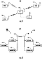
FIG. 1 shows awireless communication system 100 including a plurality of WTRUs 110, aBS 120, and a radio network controller (RNC) 130. As shown inFIG. 1 , the WTRUs 110 are in communication with theBS 120, which is in communication with theRNC 130. The WTRUs 110 are configured to receive data transmissions from theBS 120 over a high speed shared data channel. TheBS 120 and/or WTRUs 110 are configured to detect random access (RA) failures and collisions, as described herein. Although only three WTRUs 110, oneBS 120, and oneRNC 130 are shown inFIG. 1 , it should be noted that any combination of wireless and wired devices may be included in thewireless communication system 100. For example, although theRNC 130 is shown in thewireless communication system 100, theRNC 130 may not exist in thesystem 100 and may be included in theBS 120 or any other entity in thesystem 100. It should be understood that the communication between the WTRUs 110.BSes 120, and RNC 130 or other networks like the Internet may be done using packet-based communication. -
FIG. 2 is a functional block diagram 200 of the WTRU 110 and theBS 120 ofFIG. 1 . As shown inFIG. 2 , the WTRU 110 is in communication with theBS 120 and both may be configured to detect random access (RA) failures and collisions, as discussed below. - In addition to the components that may be found in a typical WTRU, the WTRU 110 includes a
processor 115, areceiver 116, atransmitter 117, and anantenna 118. Theprocessor 115 is configured to detect RA failures and collisions. Thereceiver 116 and thetransmitter 117 are in communication with theprocessor 115. Theantenna 118 is in communication with both thereceiver 116 and thetransmitter 117 to facilitate the transmission and reception of wireless data. - In addition to the components that may be found in a typical BS, the BS 120 includes a
processor 125. areceiver 126, atransmitter 127, and anantenna 128. Theprocessor 125 is configured to detect RA failures and collisions. Thereceiver 126 and thetransmitter 127 are in communication with theprocessor 125. Theantenna 128 is in communication with both thereceiver 126 and thetransmitter 127 to facilitate the transmission and reception of wireless data. -
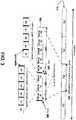
FIG. 3 shows an example of a TDD frame structure that currently corresponds to the IEEE 802.16m TDD frame structure, although other frame structures can of course be used with the embodiments described herein. Regardless of channel bandwidth (5, 7, 8.75. 10, or 20 MHz), thesuperframe 310 may be 20 ms in length as shown and may be divided into four 5ms frames 320. Theframes 320 may be further divided into 5-8subframes 330. Thesesubframes 330 may each contain, five, six, seven, or nine OFDM symbols, depending on the type ofsubframe 330 in use. - Each
TDD subframe 330 contains adownlink portion 340 and anuplink portion 350. separated by a TTG (Transmit/Receive gap) 360 and an RTG (Receive/Transmit gap) 380. inserted between transmit and receive, or receive and transmit, respectively. Downlink/Uplink ratios may vary for the 5, 7, 8.75, 10, and 20 MHz bandwidths. Some examples of Downlink/Uplink ratios are: 8/0. 6/2, 5/3, 4/4, 3/5. -
FIG. 3 shows the frame structure for 5, 10, and 20 MHz TDD with 5/3 DL/UL split. - A
single downlink frame 340 may contain multiple bursts of varying size and type carrying data for several WTRUs. The frame size could also be variable on a frame-by-frame basis. Each burst may contain multiple concatenated fixed-size or variable-size packets or fragments of packets received from higher layers. - The
uplink subframe 350 may he made up of several uplink data bursts from different WTRUs. A portion of theuplink subframe 350 may be set aside for contention-based access, also called Random Access (RA), that may be used for a variety of purposes, including ranging for UL, time, and power adjustments during network entry as well as periodically afterward. The RA channel may also be used by WTRUs to make uplink bandwidth requests. In addition, best-effort data may be sent on this contention-based channel. particularly when the amount of data to send is too small to justify requesting a dedicated channel. - In scheduling based wireless broadband access systems. Random Access (RA) refers to an uplink (UL) region that is allocated for WTRUs to access. It is also referred to as contention-based access. The UL region allocated for RA may be called a Random Access (RA) region.
- ARA region commonly includes RA channels, where a RA channel is physically modulated to carry certain information codes. The information code carried by a RA channel is called a RA code. In some RA code designs, multiple codes with certain orthogonal properties can be transmitted by different WTRUs in the same RA channel. For example, in IEEE 802.16 systems, a Code Division Multiple Access (CDMA)-like RA code may be used, so that one RA channel may be accessed by multiple WTRUs with different RA codes.
- A RA opportunity may refer to the opportunity that a WTRU uses to transmit its RA request. When a RA channel may carry multiple RA codes, a RA opportunity may be a combination of a RA channel and a RA code. When a WTRU needs to send a RA request, it may transmit a specific RA code in a RA channel.
- After sending a RA request, the WTRU waits for the BS to provide a response to its RA request that is identified by the RA opportunity that the WTRU used to send the RA request, e.g., the location of the RA region, RA channel, and ItA code. The expected response varies with the intention of the WTRU's RA request.
- The RA opportunities for different RA use cases may be identified by different RA regions allocated by the BS or by different RA codes domains / different RA channels in the same RA region, At least four use cases of Random Access (RA) may exist: initial access for a new subscriber (WTRU) to join the network (initial ranging); Handover of a subscriber (WTRU) from one BS to another BS (HO ranging); periodic maintenance of the uplink (UL) transmission parameters (periodic ranging); and bandwidth request for existing subscriber (WTRU) (contention-based bandwidth request).
- Initial ranging is a process for a new WTRU to initiate communication with a BS. The WTRU sends an initial ranging request in an initial ranging RA opportunity to the BS, for example, an initial ranging code in an Initial Ranging RA channel. After sending its initial ranging request, the WTRU waits for a response from the BS. The expected response to an initial ranging request may be a ranging status notification with or without UL transmission parameter adjustments.
- HO ranging is a process for a WTRU to initiate communication with the target BS during handover from one BS to another BS. The WTRU sends a HO ranging request in a HO ranging RA opportunity to the BS. i.e., a HO ranging code in a HO ranging RA channel. After sending its HO Ranging request, the WTRU waits for a response from the BS. The expected response to a HO ranging request may be a ranging status notification with or without UL transmission parameter adjustments.
- With respect to periodic ranging, since each WTRU may be a different distance from a BS, it may be important in the uplink to synchronize symbols in both time domain and frequency domain and equalize the received power levels among the various active WTRUs. In the uplink, the active WTRUs may need to be synchronized to at least within a cyclic prefix guard time of one another. Otherwise, significant intercarrier and intersymbol interference may result. Similarly, although downlink power control may be used in order to reduce spurious other-cell interference, it may not be not strictly required. Uplink power control may (1) improve battery life. (2) reduce spurious other-cell interference, and (3) avoid drowning out faraway WTRUs in the same cell that are sharing an Orthogonal Frequency Division Multiplexing (OFDM) symbol with them.
- This periodic ranging process, when initiated, may require the BS to estimate the channel strength and the time/frequency of the received UL signals from the WTRU in question, and then send the necessary UL transmission parameter adjustments, e.g., time, frequency, and/or power level, to the WTRU. When the WTRU uses unicast UL allocation, the BS may estimate the received unicast UL data from the WTRU to determine if UL transmission parameter adjustment is needed. When the WTRU does not have unicast UL allocation and the periodic ranging is initiated, the WTRU needs to use a periodic ranging RA opportunity to send the BS a periodic ranging request. After sending its periodic ranging request, the WTRU waits for a response from the BS. The expected response to periodic ranging request may be a ranging status notification with or without UL transmission parameter adjustments
- A contention-based bandwidth request may be a process that a WTRU uses to request UL bandwidth by sending a Bandwidth Request (BR) RA request. The WTRU may send a BR RA request in a BR RA opportunity to the BS. i.e., a BR RA code in a BR RA channel. After sending a BR RA request, the WTRU waits for a response from the BS. The expected response to a BR RA request may be an UL bandwidth grant.
- Within this or other systems, there are several embodiments that may address the latency issue of RA failure detection at the WTRU. Generally, the embodiments may use BS assistance to help the WTRUs in the RA-failure detection, so that the WTRUs may detect the failures of their RA attempts timely and accurately, and then start their RA recovery processes accordingly.
- In a first embodiment, the BS may send responses to all the received RA requests in a RA region in the same aggregate BS RA response message and this aggregate BS response may be sent at the earliest possible BS RA response opportunity. Depending on the purpose of the RA request, the BS RA responses may be ranging status notifications with or without parameter adjustments. resource allocations, or simple acknowledgements indicating a successful reception of the RA request.
- In the event that no RA request is successfully received by the BS in a RA region, the BS may not transmit the response message or the BS may transmit a null message.
- Upon receiving and decoding a BS RA response message that contains responses to the successful received WTRU RA requests, a WTRU may deterministically detect if its own RA request was successfully received at the BS. The WTRU does this by checking whether the aggregate BS RA response message contains a response to its RA request, for example, a RA channel plus a RA code in 802.16 systems. If the aggregate BS RA response message does not contain any response to its RA request, the WTRU may consider that its RA request failed and then start its RA recovery process. This recovery process could begin immediately, without waiting for a timer out, such that the latency of RA failure detection at WTRU side is significantly reduced.
- Another benefit of using an aggregate BS RA message may be overhead reduction as the BS sends the responses to all the received RA requests in the same aggregate BS RA response message, compared to sending an individual TA response message to each RA request. The overhead reduction comes from saving multiple message headers and having a more efficient way to identify the RA opportunities in one aggregate message rather than identifying them each individually in separate messages.
- For example, the BS may allocate a ranging RA region in the UL in order to provide initial ranging opportunities for the new WTRUs to join the network. A new WTRU, after acquiring the essential system configuration parameters and synchronized with the downlink (DL) of the BS, may start the initial ranging process by sending an initial ranging request, i.e., transmitting a selected initial ranging RA code in a selected initial ranging channel. After receiving and decoding an initial ranging region, the BS may send an aggregate RA response message at the earliest possible BS initial ranging RA response opportunity. The aggregate RA response message may contain initial ranging RA responses to all the successfully received and decoded initial ranging RA requests in the initial ranging RA region. For each successfully received and decoded initial ranging request, the BS's RA response may contain the ranging status and the necessary UL transmission parameter adjustments.
- As shown in
FIG. 4 , after an UL initial rangingregion 1010. the earliest BS initial ranging RA response opportunity may be determined by the BS's scheduler that manages and allocates the radio link resources based on the BS's real-time traffic load and traffic composition. For an initial ranging region inframe n 1000. the earliest BS initial rangingRA response opportunity 1035 may be aDL frame 1020 of frame n+1 1030, i.e., the next DL frame after the UL frame with the initial ranging region, if the BS scheduler can accommodate the initial ranging RA aggregate response message in it after other higher priority traffic data; otherwise, the earliest BS initial rangingRA response opportunity 1045 may be the DL frame of frame n+2 1040 or later. - After sending an initial ranging RA request, the WTRU waits for the initial ranging RA response from the BS. Once the initial ranging RA response message is received and decoded, the WTRU attempts to identify the response to its request based on the used initial ranging RA channel and initial ranging RA code. If the BS aggregate initial ranging RA response message contains a response to the WTRU's request, the WTRU may consider its initial ranging RA request successful and moves to the next step according the given response. If the BS initial ranging RA aggregate response message does not contain a response to the WTRU's request, the WTRU may consider its initial ranging RA request failed and it can immediately start the initial ranging RA recovery process.
- The use of a BS initial ranging RA response message containing the responses to all successfully received and decoded initial ranging RA requests in an initial ranging region may make it possible for the WTRUs to timely and deterministically detect the status of their initial ranging RA attempts. If a WTRU detects a failure of its initial ranging RA request, the initial ranging RA recovery process may be started immediately, minimizing the latency in the initial ranging RA failure detection and recovery.
- Comparing this to a method where the BS sends separate initial ranging responses to each successfully received and decoded initial ranging RA request, the aggregation of the responses to the successfully received and decoded initial ranging RA requests in one BS initial ranging RA response message reduces the overhead of MAC encodings, as it saves multiple MAC headers and also it may have more efficient way to identify the RA requests when aggregating them together.
- An initial ranging RA timer may still be used to handle the exceptions, such as message delivery errors, in order to improve overall system robustness.
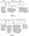
- A similar embodiment may also be applied to the HO ranging RA process where the HO ranging RA opportunities may be in a separate RA region. Alternatively, as shown in
FIG. 5 the HO ranging RA opportunities may share the same RA region 1110 as initial ranging opportunities as shown inframe n 1100. For example, in IEEE 802.16 systems, the initial ranging and HO ranging may share the same RA region where they are distinguished by using different RA codes. - When the HO ranging shares the same RA region with the initial ranging, the BS may send one
RA response message 1135 containing the responses to all successfully received and decoded initial ranging RA requests and HO ranging RA requests at the earliest BS initial/HO ranging response opportunity (in frame n+1 1130 for the HO ranging RA request). Alternatively, the BS may send two separate aggregateRA response messages - In addition, a similar embodiment may also be applied to periodic ranging RA process. Similarly, the periodic ranging RA opportunities may be in a separate RA region. In this case, after each periodic ranging RA region, the BS sends a periodic ranging RA response message containing the RA responses to all successfully received and decoded periodic ranging RA requests, at the earliest possible BS periodic ranging response time.
- The periodic ranging RA region may have a different PHY channel design from the initial ranging / HO ranging RA region, as it may be for the random access from the WTRUs that have been synchronized with the BS in the UL.
- Alternatively, the periodic ranging RA opportunities may share the same RA region with other ranging types, e.g.. initial ranging and/or HO ranging. In this case, after each ranging RA region, the BS may sends one single ranging RA response message containing the RA responses to all successfully receive and decoded ranging RA requests including all ranging types, at the earliest possible BS ranging RA response time. Alternatively, the BS may sends multiple ranging RA response message, one for each ranging types or any combinations of the ranging types supported in the ranging RA region, at the same or different earliest RA response time.
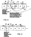
- In another embodiment, with the contention-based bandwidth Request RA, the BS RA response messages may contain the resource allocations that may be located in the next UL region or spread in the next multiple UL regions. As shown in a simplified frame shown in
FIG. 6 , for theRA region 602 in frame n-1 600, the BS sends a BS RAaggregate response message 611 in theDL 612 offrame n 610, which contains the responses to all the correctly received RA requests, where theresponses 611 may contain theresource allocations 616 inframe n 610 or the nextseveral frames 620. - The
BS response 611 may also indicate a future sub-frame where UL resource allocation control signal, e.g., Advanced-MAP (A-MAP) in IEEE 802.16m, containing the actual allocation may be found. - In this way, the BS RA
aggregate response 611 also serves as the acknowledgement to the WTRUs for their bandwidth request RA requests sent in the previous bandwidth request RA region. That is. the BS RA aggregate response message may serve two functions: one to allocate resources; and the other to acknowledge WTRUs that used the previous RA region. - For a WTRU that used a RA opportunity for an UL bandwidth request in the previous bandwidth request RA region, if the WTRU receives the expected response from the BS RA aggregate response, it may consider that its RA attempt was successful and also knows where its UL unicast allocation is. If the WTRU does not receive its expected response in the BS RA response, it may recognize that its RA attempt failed and it may start the recovery process immediately or at such time as makes sense.
- In another embodiment, after sending a RA request, if the WTRU does not receive a response in the RA response message from the BS, it may start the RA recovery procedure, unless a maximum number of allowed RA attempts have been reached.
- Alternatively, in another embodiment, an expliciL ACK may be sent immediately upon detection of the RA request. For a RA request that requires resource allocation, the actual resource grant may be sent at a later time when resources are available.
- Upon receiving an ACK for a RA request requiring resource allocation, the WTRU may start a timer. Expiration of the timer without grant/response may be a cause for the WTRU to retry the access procedure. This may prevent the WTRU from waiting too long in the event of a reception error.
- In another embodiment, in the BS RA aggregate response message, the successfully received and decoded RA requests are identified by the RA opportunity descriptors, e.g., the RA region, the RA channel, and the RA code (as used, for example in IEEE 802.16 systems), or identifiers derived from the RA opportunity descriptors. If the RA opportunity descriptors are used in the BS RA response message for a RA region, the coding efficiency may be improved hy using a two-level list, i.e., listing the RA channels with at least one RA code received and decoded and then, for each listed RA channel, listing all received and decoded RA codes, comparing to using an one-level list of the pairs (RA channel. RA Code) for the received and decoded RA opportunities.
- In another embodiment, the ACK may be sent per code and RA channel combination, together called a RA opportunity, RA opportunities may be partitioned into groups. For each group, all successfully received RAs are signaled. For each access group with N opportunities, up to Kmax received RAs may be signaled. The number K may be signaled, which requires log2 (Kmax) bits. An index to the combination of successful RA's may be signaled, which requires log2(N over K) bits. An index may be reserved to signal the event where K > Kmax.
- In another embodiment, the BS assists the WTRUs to have an improved time period for the RA timer that is dynamic and varies with the system loads. For example, for the RA requests resource allocations, when the system is lightly loaded, the required resources can be allocated quickly, therefore the RA timer value can be smaller. When the system is heavily loaded, then the required resources will be allocated spreading in the time domain, therefore the timer value should be larger. It is difficult or impossible for the WTRUs to dynamically change their RA timer because the WTRU does not have the system loading information without being informed by the BS. With BS assistance, after the BS receives/processes a RA region, it sends out a broadcast message, telling the WTRUs the RA timer values for the given RA region, based on the BS's knowledge about how long it will take to finish responding to those correctly received RA requests. Alternatively, sending time is unspecified and the WTRU follows the last RA timer value available.
- When multiple classes of RA requests are supported, if the RA class information is provided in the received RA requests, the BS may also send multiple RA time values, each for a specific RA request class. An RA timer setting broadcast message may be very short, as it only contains small numbers, i.e. the RA timer values. This proposed embodiment may also apply to the detections of both collision-caused RA failure and power-too-low-caused RA failure. If the WTRU does not receive the expected RA response within the given time, it may start the RA recovery procedure unless the maximum number of allowed RA attempts has been reached.
- In a first method to address collisions, all wireless transmit/receive units (WTRUs) may use distinct codes, however due to receiver limitations, more codes are used than can he detected. The first result may be that not all codes are detected, but those that are detected are correct. This is a problem only if all WTRUs choose the same channel again. The second result is that false detections are made. This would be a low probability event and the recovery from it would be in a verification stage.
- A first embodiment may address the UL data collision problem caused by missed-detection of RA collisions when UL Hybrid Automatic Repeat Request (HARQ) is not used. A missed-detection of RA collision happens when the BS erroneously detects a single RA request 1210 (in
FIG. 7 ) in a RA opportunity that had a RA collision, i.e.. accessed by two or more WTRUs. If the expectedRA response 1235 may involve a unicast UL data allocation, for example, in the contention-based UL bandwidth request RA process, the BS may allocate a unicast UL allocation to the decoded RA request 1210. However, two or more WTRUs that used the same RA opportunity 1210 may then transmit in the UL allocation 1238, thus resulting in data region collision. - When UL HARQ is not used for the UL transmission, the involved WTRUs may detect the UL data region collision by a failure of receiving the expected response from the BS to their UL data if their UL data requires certain response, for example, as part of hand-shaking protocol data; otherwise, the involved WTRUs may not be able to detect such an UL data region collision at the MAC layer. The proposed embodiment may use the BS's assistance to the WTRUs in detecting such an UL data region collisions. The BS has the knowledge about which UL data allocation is for a RA response and the BS also has the knowledge if the UL data region has been successfully received. Therefore, in case of UL data region collision, the BS can use its knowledge to send an indication to the WTRUs to inform the failure of reception of the UL data region allocated for a RA request. Such an indication of UL data region collision may be called as RA-initiated UL data Negative-ACKnowledgement (NACK).
- When the WTRUs that used the given UL allocation receive such a RA-initiated UL data NACK from the BS, they may realize that an error occurred in their "on-going" procedure, and an error recovery is needed.
- In a RA-initiated
UL data NACK 1245 sent by the BS, the UL data region may be identified by the RA request to which the UL data allocation was given as the response, where the RA request may be identified by the RA request descriptors, for example, the RA region, the RA channel, and the RA code. or an identifier derived from these RA descriptors. - In a RA-initiated
UL data NACK 1245 sent by the BS, the UL data region may also be identified by the UL data allocation descriptors, for example, frame index, subframe index, LRU (Logical Resource Unit) index, etc, or an identifier derived from these UL allocation descriptors. - The BS may send a RA-initiated
UL data NACK 1245 as a MAC control signal, for example, in the IEEE 802.16 systems, such a RA-initiated UL data NACK may be encoded as a control message, a control signaling header, or a subheader or extended header of a MAC PDU (Protocol Data Unit), or an Advanced-MAP (A-MAP) Information Element (IE). - Another embodiment may address the UL data collision problem caused by missed-detection of a RA collision when UL HARQ is used. In this case, the UL data collision caused by missed-detection of a RA collision may cause substantial resource waste, because it may force the collided WTRUs to repeatedly retransmit and hence re-collide until reaching the max allowed number of HARQ retransmissions. With UL HARQ, detecting an UL data region collision may require additional attempts and/or other techniques than just normal UL data HA RQ decoding, because a single burst error may he difficult to tell it is the result of normal link error or a collision.
- As shown in
FIG. 8 . multipleRA request opportunities 1310 are transmitted in a frame n in an uplink, and in the frame n+1 the BS aggregateRA response message 1335 provides responses to theRA request 1310 and other requests. After receiving and decoding the first UL transmission in an UL data allocation as the response to aRA request 1310, the BS may still be able to detect a collision. For example, the BS may consider a collision is detected if the UL data region 1338 experiences an abnormally high level of errors based on the channel coding, such as Incremental Redundancy HARQ (IR HARQ), or if it observes other abnormal physical signal changes, e.g., channel delay spread. - When receiving and decoding a subsequent UL HARQ retransmission 1338 but before reaching the maximum number of HARQ retransmissions, the BS may be able to detect a collision in an UL data allocation as the response to a RA request. For example, the BS may consider a collision is detected if it observes no gain has been obtained from the UL HARQ retransmissions.
- Once detected, an UL data region collision may be handled by using the BS's assistance to help the WTRUs to timely detect the error condition stop UL HARQ retransmissions, and enter an error recovery process. The BS assistance may be an indication signal sent by the BS to the WTRUs, e.g., a RA-initiated UL data Negative ACKnowledgement (NACK) 1350 in the downlink in frame n+3 in
FIG. 8 . - When receiving such a RA-initiated
UL data NACK 1350 from the BS, the WTRU may stop the HARQ retransmission process and enter the random access recovery process immediately. - Similar to the previous embodiment, the RA-initiated
UL data NACK 1350 signaled by the BS may be encoded as a MAC control signal, for example, in the IEEE 802.16 systems, a control message, or a control signaling header, or a subheader or extended header of a MAC PDU (Protocol Data Unit), or an Advanced-MAP (A-MAP) Information Element (IE). - In addition, if the synchronized UL HARQ is used, the RA-initiated UL data NACK sent by the BS may be the same control signal used to terminate the synchronized UL resource allocations for
UL HARQ retransmissions 1350, for example in frame n+3 inFIG. 9 . For example, in IEEE 802.16 systems, a CDMA allocation A-MAP IE with zero allocation can be used by the BS to signal the RA-initiated UL data NACK and also to terminate the synchronized UL resource allocations for UL HARQ retransmissions. - Also, if the non-synchronized UL HARQ is used, the RA-initiated UL data NACK signaled by the BS may be a combination of UL HARQ NACK and no UL resource allocated for the HARQ retransmission within a pre-defined time interval after the previous HARQ transmission or retransmission.
- Alternatively, if the non-synchronized UL HARQ is used, the RA-initiated UL data NACK signaled by the BS may he a combination of UL HARQ NACK and zero UL resource allocation for the HARQ retransmission. For example, in IEEE 802.16 systems, zero UL resource allocation may be a CDMA allocation A-MAP IE with zero allocation.
- When using the zero allocation for the UL HARQ retransmission for an UL allocation following a RA request to terminate its UL HARQ retransmission process, the intended WTRUs may be identified by the previously used RA opportunity descriptors, for example, the RA region, the RA channel, and the RA code, or an identifier derived from these RA descriptors.
- Alternatively, when using the zero allocation for the UL HARQ retransmission for an UL allocation following a RA request to terminate its UL HARQ retransmission process, its intended WTRUs may be identified by the previously used UL data allocation descriptors, for example, frame index, subframe index, LRU (Logical Resource Unit) index, etc, or an identifier derived from these UL allocation descriptors.
- When using the zero allocation for the UL HARQ retransmission for an UL allocation following a RA request to terminate its UL HARQ retransmission process, the identifiers of its intended WTRUs may be included as information field in the zero allocation control signal or may be masked with the Cyclic Redundancy Check (CRC) of the zero allocation control signal.
- The zero allocation control signal may be encoded as a stand-alone UL resource allocation information element, for example, a stand-alone A-MAP IE, where its type value indicates the zero UL allocation.
- Alternatively, the zero allocation control signal may be encoded as a special case of the UL allocation IE for the UL allocation following a RA request, for example, the CDMA Allocation IE, where the special case may be indicated by a specific value of an information field in the UL allocation IE.
- Another embodiment may address the UL data collision problem caused by missed-detection of RA collisions when UL HARQ is used. The BS may configure a limited number of UL HARQ retransmissions for the UL data region allocated as a response to a RA request, where such a limited number is less than maximum number of UL HARQ retransmissions for other UL allocations. With this embodiment, the WTRU that transmits in an UL allocation following a RA request may exist the UL HARQ retransmission when transmitted n times including the original transmission, where 1 ≤ n ≤ Max_num_HARQ_retransmissions. The value of n may be decided by system configuration. The n-th HARQ NACK from the BS also indicates the termination of the HARQ retransmission process. When receiving the n-th HARQ NACK, the WTRU terminates the UL HARQ retransmission and may enter the random access recovery process.
- Another embodiment may address the collision problem where not all codes are detected and where nothing is detected. This embodiment uses a recovery mechanism such that the WTRU may randomize its choice of slot and codes.
- Another embodiment may address the RA collision problem where a RA collision is detected. In this example, the BS may send a NACK to notify the WTRUs that the RA failures that the BS detected in the previous RA region are due to collisions. The benefit of sending a NACK and not an ACK is in reduced overhead as NACK signals are the exception rather than the rule.
-
FIG. 9 is a diagram of a frame using BS-Assistance information in a RA timer or a NACK. When a BS detects a collision in RA. at the next DL opportunity, the BS may send aNACK message 613 to inform the subscribers of the detected collision. This will simultaneously eliminate/minimize the false detection at the WTRU side and reduce the RA latency significantly. The proposed NACK mechanism may be an addition to the WTRU timer-based mechanism, not a replacement. A timer-based mechanism may be employed to be the backup mechanism in certain scenarios. - The embodiments discussed herein may address the detections of both collision-caused RA failure and insufficient signal power RA failure, as well as other causes RA failure.
- Although features and elements are described above in particular combinations, each feature or element can be used alone without the other features and elements or in various combinations with or without other features and elements. The methods or flow charts provided herein may be implemented in a computer program, software, or firmware incorporated in a computer-readable storage medium for execution by a general purpose computer or a processor. Examples of computer-readable storage mediums include a read only memory (ROM), a random access memory (RAM), a register, cache memory, semiconductor memory devices, magnetic media such as internal hard disks and removable disks, magneto-optical media, and optical media such as CD-ROM disks, and digital versatile disks (DVDs).
- Suitable processors include, by way of example, a general purpose processor, a special purpose processor, a conventional processor, a digital signal processor (DSP), a plurality of microprocessors, one or more microprocessors in association with a DSP core, a controller, a microcontroller. Application Specific Integrated Circuits (ASICs), Field Programmable Gate Arrays (FPGAs) circuits, any other type of integrated circuit (IC), and/or a state machine.
- A processor in association with software may be used to implement a radio frequency transceiver for use in a wireless transmit receive unit (WTRU), user equipment (UE). terminal, base station, radio network controller (RNC), or any host computer. The WTRU may be used in conjunction with modules, implemented in hardware and/or software, such as a camera, a video camera module, a videophone, a speakerphone, a vibration device, a speaker, a microphone, a television transceiver, a hands free headset, a keyboard, a Bluetooth® module, a frequency modulated (FM) radio unit, a liquid crystal display (LCD) display unit, an organic light-emitting diode (OLED) display unit, a digital music player, a media player, a video game player module, an Internet browser, and/or any wireless local area network (WLAN) or Ultra Wide Band (UWB) module.
Claims (16)
- A wireless transmit/receive unit, WTRU, comprising:a processor; anda transceiver,the processor and the transceiver are configured to acquire a first random access configuration and a second random access configuration, wherein the first random access configuration and the second random access configuration are different,the processor and the transceiver are further configured to perform a first random access procedure using the first random access configuration using first physical resources and a second random access procedure using the second random access configuration using second physical resources, wherein the first random access configuration is used for at least initial random access and the second random access configuration is used for timing adjustments, wherein the first physical resources are different physical resources than the second physical resources, andthe processor and the transceiver are further configured to receive a first message for the first random access procedure and to receive a second message for the second random access procedure, wherein the first message is an aggregated response message including a plurality of first random access responses and the second message is an aggregated response message including a plurality of second random access responses.
- The WTRU of claim 1, wherein the second random access configuration is used for periodic random access.
- The WTRU of claim 1, wherein the processor is further configured for each of the first message and the second message to identify one of the random access responses as being for the WTRU using a code indicated in the identified random access response.
- The WTRU of claim 1, wherein the first random access procedure is further used for handover random access.
- The WTRU of claim 1, wherein the second random access configuration is further used for power adjustments.
- The WTRU of claim 1, wherein the first random access configuration includes at least one random access code for use in the first random access procedure and the second random access configuration includes at least one random access code for use in the second random access procedure.
- The WTRU of claim 1, wherein the second random access procedure is for WTRUs that have been synchronized with a base station in the uplink.
- The WTRU of claim 7, wherein the first random access procedure is for WTRUs that have been synchronized with the base station in the downlink.
- A method comprising:acquiring, by a wireless transmit/receive unit, WTRU, a first random access configuration and a second random access configuration, wherein the first random access configuration and the second random access configuration are different;performing, by the WTRU, a first random access procedure using the first random access configuration using first physical resources and a second random access procedure using the second random access configuration using second physical resources, wherein the first random access configuration is used for at least initial random access and the second random access configuration is used for timing adjustments, wherein the first physical resources are different physical resources than the second physical resources, andreceiving a first message for the first random access procedure and receiving a second message for the second random access procedure, wherein the first message is an aggregated response message including a plurality of first random access responses and the second message is an aggregated response message including a plurality of second random access responses.
- The method of claim 9, wherein the second random access configuration is used for periodic random access.
- The method of claim 9, further comprising identifying, for each of the first message and the second message, one of the random access responses as being for the WTRU using a code indicated in the identified random access response.
- The method of claim 9, wherein the first random access procedure is further used for handover random access.
- The method of claim 9, wherein the second random access configuration is further used for power adjustments.
- The method of claim 9, wherein the first random access configuration includes at least one random access code for use in the first random access procedure and the second random access configuration includes at least one random access code for use in the second random access procedure.
- The method of claim 9, wherein the second random access procedure is for WTRUs that have been synchronized with a base station in the uplink.
- The method of claim 15, wherein the first random access procedure is for WTRUs that have been synchronized with the base station in the downlink.
Applications Claiming Priority (5)
| Application Number | Priority Date | Filing Date | Title |
|---|---|---|---|
| US17207209P | 2009-04-23 | 2009-04-23 | |
| US18370009P | 2009-06-03 | 2009-06-03 | |
| PCT/US2010/032243 WO2010124209A1 (en) | 2009-04-23 | 2010-04-23 | Base station assistance for random access performance improvement |
| EP10716673A EP2422573A1 (en) | 2009-04-23 | 2010-04-23 | Base station assistance for random access performance improvement |
| EP17194398.8A EP3282805B1 (en) | 2009-04-23 | 2010-04-23 | Base station assistance for random access performance improvement |
Related Parent Applications (2)
| Application Number | Title | Priority Date | Filing Date |
|---|---|---|---|
| EP17194398.8A Division EP3282805B1 (en) | 2009-04-23 | 2010-04-23 | Base station assistance for random access performance improvement |
| EP10716673A Division EP2422573A1 (en) | 2009-04-23 | 2010-04-23 | Base station assistance for random access performance improvement |
Publications (2)
| Publication Number | Publication Date |
|---|---|
| EP3611993A1 EP3611993A1 (en) | 2020-02-19 |
| EP3611993B1 true EP3611993B1 (en) | 2021-06-02 |
Family
ID=42341413
Family Applications (3)
| Application Number | Title | Priority Date | Filing Date |
|---|---|---|---|
| EP17194398.8A Active EP3282805B1 (en) | 2009-04-23 | 2010-04-23 | Base station assistance for random access performance improvement |
| EP10716673A Withdrawn EP2422573A1 (en) | 2009-04-23 | 2010-04-23 | Base station assistance for random access performance improvement |
| EP19200711.0A Active EP3611993B1 (en) | 2009-04-23 | 2010-04-23 | Base station assistance for random access performance improvement |
Family Applications Before (2)
| Application Number | Title | Priority Date | Filing Date |
|---|---|---|---|
| EP17194398.8A Active EP3282805B1 (en) | 2009-04-23 | 2010-04-23 | Base station assistance for random access performance improvement |
| EP10716673A Withdrawn EP2422573A1 (en) | 2009-04-23 | 2010-04-23 | Base station assistance for random access performance improvement |
Country Status (11)
| Country | Link |
|---|---|
| US (3) | US20100272066A1 (en) |
| EP (3) | EP3282805B1 (en) |
| JP (5) | JP2012525082A (en) |
| KR (6) | KR102078980B1 (en) |
| CN (3) | CN104735806B (en) |
| AR (1) | AR076390A1 (en) |
| AU (1) | AU2010238652B2 (en) |
| HK (1) | HK1250579B (en) |
| MX (1) | MX2011011066A (en) |
| TW (3) | TWM392517U (en) |
| WO (1) | WO2010124209A1 (en) |
Families Citing this family (28)
| Publication number | Priority date | Publication date | Assignee | Title |
|---|---|---|---|---|
| KR101138523B1 (en) * | 2007-01-05 | 2012-06-04 | 인터디지탈 테크날러지 코포레이션 | Backoff mechanism in random access channel |
| TWM392517U (en) * | 2009-04-23 | 2010-11-11 | Interdigital Patent Holdings | Base station assistance for random access performance improvement |
| CN102474790B (en) * | 2009-07-06 | 2015-11-25 | 瑞典爱立信有限公司 | The Controlling vertex improved |
| KR101612558B1 (en) * | 2009-08-28 | 2016-04-15 | 엘지전자 주식회사 | Method for transmitting frames in a wireless communication system including relay station |
| EP2481245A1 (en) * | 2009-09-24 | 2012-08-01 | Nokia Siemens Networks OY | Method for dynamically controlling an uplink transmission power of a user equipment |
| US8830908B2 (en) | 2011-02-18 | 2014-09-09 | Qualcomm Incorporated | Apparatus and method for facilitating fallback access schemes |
| EP2564611B1 (en) | 2011-07-01 | 2015-02-18 | Ofinno Technologies, LLC | Synchronization signal and control messages in multicarrier OFDM |
| US8369280B2 (en) | 2011-07-01 | 2013-02-05 | Ofinno Techologies, LLC | Control channels in multicarrier OFDM transmission |
| US8582527B2 (en) | 2011-07-01 | 2013-11-12 | Ofinno Technologies, Llc | Hybrid automatic repeat request in multicarrier systems |
| TWI457031B (en) * | 2011-12-01 | 2014-10-11 | Acer Inc | Mobile communication devices, radio base stations, multi-carrier systems, and methods for handling random access failures |
| US8914017B2 (en) * | 2011-12-01 | 2014-12-16 | Acer Incorporated | Mobile communication devices, cellular stations, multi-carrier systems, and methods for handling random access failures |
| KR20130061628A (en) * | 2011-12-01 | 2013-06-11 | 에이서 인코포레이티드 | Mobile communication devices, cellular stations, multi-carrier systems, and methods for handling random access failures |
| US8842637B2 (en) | 2011-12-04 | 2014-09-23 | Ofinno Technologies, Llc | Carrier information transmission to wireless devices |
| US9185725B2 (en) | 2011-12-15 | 2015-11-10 | Nokia Technologies Oy | Request-response procedure for wireless network |
| US9497756B2 (en) | 2012-03-25 | 2016-11-15 | Comcast Cable Communications, Llc | Base station radio resource management |
| US9949265B2 (en) | 2012-05-04 | 2018-04-17 | Comcast Cable Communications, Llc | Control channel in a wireless communication system |
| WO2015014391A1 (en) * | 2013-07-30 | 2015-02-05 | Telefonaktiebolaget L M Ericsson (Publ) | Exploiting almost blank subframes for inter-cell scheduling |
| CN104640229A (en) * | 2013-11-06 | 2015-05-20 | 株式会社Ntt都科摩 | UE accessing method, UE and base station |
| CN105095199B (en) * | 2014-04-16 | 2019-04-09 | 阿里巴巴集团控股有限公司 | Business data processing method, device and system |
| CN106162923A (en) * | 2015-04-10 | 2016-11-23 | 中兴通讯股份有限公司 | Random access signaling resend method and device |
| EP3286974B1 (en) * | 2015-04-24 | 2022-04-06 | Nokia Technologies Oy | Common random access channel resource based coordinated random access |
| KR102394199B1 (en) * | 2015-05-26 | 2022-05-04 | 삼성전자주식회사 | Method and apparatus for performing random access in wireless communication system |
| WO2018176407A1 (en) * | 2017-03-31 | 2018-10-04 | 富士通株式会社 | Random access method, device and communications system |
| EP3625990B1 (en) * | 2017-09-21 | 2021-07-07 | Guangdong Oppo Mobile Telecommunications Corp., Ltd. | Resource selection method, device and computer storage medium |
| CN111713135B (en) * | 2018-02-14 | 2023-02-17 | 上海诺基亚贝尔股份有限公司 | Method and apparatus for prioritized random access during handover |
| FR3080254A1 (en) * | 2018-04-13 | 2019-10-18 | Orange | WIRELESS COMMUNICATION DEVICES, SYSTEMS, AND METHODS FOR ESTABLISHING CRITICAL SERVICES IN LATENCY |
| CN113826026A (en) * | 2019-05-14 | 2021-12-21 | 三星电子株式会社 | Electronic device for performing ranging by UWB and operating method for electronic device |
| WO2021030023A1 (en) * | 2019-08-14 | 2021-02-18 | Google Llc | Accessing a communication channel by multiple user devices at the same time |
Family Cites Families (55)
| Publication number | Priority date | Publication date | Assignee | Title |
|---|---|---|---|---|
| US6606313B1 (en) | 1998-10-05 | 2003-08-12 | Telefonaktiebolaget Lm Ericsson (Publ) | Random access in a mobile telecommunications system |
| US6519449B1 (en) * | 1999-10-29 | 2003-02-11 | Nortel Networks Limited | Method and apparatus for a signal power control in a wireless communication system |
| KR100566201B1 (en) * | 2002-04-22 | 2006-03-29 | 삼성전자주식회사 | Method for ranging in mobile communication system using orthogonal frequency division multiple access scheme |
| KR100594110B1 (en) * | 2003-03-08 | 2006-07-03 | 삼성전자주식회사 | System and method for implementing a handoff in a traffic state in a broadband wireless access communication system |
| KR100665425B1 (en) * | 2003-03-08 | 2007-01-04 | 삼성전자주식회사 | System and method for performing handover operation in a mobile communication system |
| KR100606129B1 (en) * | 2003-04-30 | 2006-07-28 | 삼성전자주식회사 | Method for measuring and reporting channel quality in broadband wireless access communication system |
| CN1549610A (en) * | 2003-05-09 | 2004-11-24 | 北京三星通信技术研究有限公司 | Method for providing multi-stage insertion service in public insertion information channel |
| KR100651541B1 (en) * | 2003-07-30 | 2006-11-28 | 삼성전자주식회사 | Method for ranging in mobile communication system using orthogonal frequency division multiple access scheme |
| KR20050015119A (en) * | 2003-08-04 | 2005-02-21 | 삼성전자주식회사 | Apparatus for modulation ranging signals in broadband wireless access communication system and method thereof |
| US7515541B2 (en) | 2003-08-08 | 2009-04-07 | Intel Corporation | Transmission of data with feedback to the transmitter in a wireless local area network or the like |
| US7430418B2 (en) * | 2003-09-04 | 2008-09-30 | Samsung Electronics Co., Ltd. | System and method for selecting a serving base station according to a drop of a mobile subscriber station in a broadband wireless access communication system |
| KR20050024085A (en) * | 2003-09-04 | 2005-03-10 | 삼성전자주식회사 | Method for performing the uplink access in broadband mobile communication system |
| KR100651430B1 (en) * | 2003-11-07 | 2006-11-28 | 삼성전자주식회사 | System and method for handover in a communication system |
| KR100969755B1 (en) * | 2003-11-29 | 2010-07-13 | 삼성전자주식회사 | System and method for ranging for fast handover in a mobile communication system using orthogonal frequency division multiplexing/orthogonal frequency division multiple access scheme |
| KR100735337B1 (en) * | 2004-03-05 | 2007-07-04 | 삼성전자주식회사 | System and method for periodic ranging in sleep mode in sleep mode in a broadband wireless access communication system |
| KR100754658B1 (en) * | 2004-03-12 | 2007-09-03 | 삼성전자주식회사 | Method for operation of hybrid automatic repeat request in a broadband wireless communication system |
| AU2005241841B2 (en) * | 2004-05-07 | 2008-12-04 | Nokia Technologies Oy | System and method for periodic ranging in a sleep mode in a BWA communication system |
| KR100606084B1 (en) * | 2004-08-17 | 2006-07-28 | 삼성전자주식회사 | System and method for sleep id update of mobile station in a broadband wireless access communication system |
| KR100600674B1 (en) * | 2004-12-07 | 2006-07-18 | 한국전자통신연구원 | A terminal in wireless system and ranging method for changing dynamically ranging period thereof |
| US7664076B2 (en) * | 2004-12-13 | 2010-02-16 | Electronics And Telecommunications Research Institute | Random access apparatus and method |
| KR100933131B1 (en) * | 2005-01-08 | 2009-12-21 | 삼성전자주식회사 | Ranging Slot Allocation System and Method in Broadband Wireless Access Communication System |
| US20060209734A1 (en) * | 2005-03-09 | 2006-09-21 | Samsung Electronics Co., Ltd. | System and method for allocating and indicating ranging region in a broadband wireless access communication system |
| US7664480B2 (en) * | 2005-03-24 | 2010-02-16 | Lg Electronics Inc. | Method of connecting to network in broadband wireless access system |
| KR100729728B1 (en) * | 2005-12-09 | 2007-06-20 | 한국전자통신연구원 | Apparatus and method for processing ranging channel of ofdma system |
| KR100656981B1 (en) * | 2005-12-30 | 2006-12-14 | 포스데이타 주식회사 | Apparatus and method for controlling ranging of mobile terminals in wireless communication system |
| KR20070080552A (en) * | 2006-02-07 | 2007-08-10 | 엘지전자 주식회사 | Method for transmitting response information in the mobile communication system |
| KR100965657B1 (en) * | 2006-02-07 | 2010-06-23 | 삼성전자주식회사 | Method and system for ranging in a communication system |
| KR20070098385A (en) * | 2006-03-29 | 2007-10-05 | 삼성전자주식회사 | System and method for achieving in communication system |
| CN101064911B (en) * | 2006-04-28 | 2012-08-22 | 上海贝尔阿尔卡特股份有限公司 | Switch control method, relay station and base station for wireless access system |
| EP1876846B1 (en) | 2006-07-03 | 2009-09-09 | Samsung Electronics Co., Ltd. | System and method for performing periodic ranging in sleep mode in a communication system |
| KR20080007289A (en) * | 2006-07-15 | 2008-01-18 | 엘지전자 주식회사 | Method for acquiring the information of other type network for handover |
| US8259688B2 (en) * | 2006-09-01 | 2012-09-04 | Wi-Lan Inc. | Pre-allocated random access identifiers |
| US7804799B2 (en) | 2006-12-29 | 2010-09-28 | Intel Corporation | Uplink contention based access with quick access channel |
| WO2009002032A1 (en) | 2007-06-22 | 2008-12-31 | Lg Electronics Inc. | A method of random access and a method of transporting information in broadband wireless access system |
| KR101366332B1 (en) * | 2007-04-19 | 2014-02-21 | 엘지전자 주식회사 | A method of automatic repeat request(ARQ) in communication system |
| CN101321371A (en) * | 2007-06-05 | 2008-12-10 | 华为技术有限公司 | Accidental access response method, system and device |
| JP5117776B2 (en) * | 2007-07-03 | 2013-01-16 | 京セラ株式会社 | Terminal device, communication method, program, processor, storage medium |
| KR101365871B1 (en) * | 2007-07-06 | 2014-02-21 | 엘지전자 주식회사 | Method for performing ranging procedure |
| JP4386108B2 (en) * | 2007-07-11 | 2009-12-16 | 日本電気株式会社 | Time division multiplexing system and transmission timing control method thereof |
| US8169992B2 (en) * | 2007-08-08 | 2012-05-01 | Telefonaktiebolaget Lm Ericsson (Publ) | Uplink scrambling during random access |
| JP5140352B2 (en) * | 2007-09-07 | 2013-02-06 | インテル コーポレイション | Random access signal designation method and communication method, and base station apparatus using them |
| KR100968769B1 (en) * | 2007-09-11 | 2010-07-08 | 삼성전자주식회사 | Apparatus and method for random access in wireless communication system |
| JP2009071585A (en) * | 2007-09-13 | 2009-04-02 | Sumitomo Electric Ind Ltd | Base station apparatus, and adjusting method of mobile terminal transmission output |
| CA2693140C (en) * | 2007-09-24 | 2014-07-15 | Zte Corporation | Terminal random access method for cellular radio communications system and method for generating group identifier |
| JP2009081685A (en) * | 2007-09-26 | 2009-04-16 | Sharp Corp | Mobile communication system, base station device, mobile station device, and random access method |
| US20100226324A1 (en) * | 2007-10-08 | 2010-09-09 | Hyun Woo Lee | Method of transmitting control signals in wireless communication system |
| WO2009080423A1 (en) | 2007-12-19 | 2009-07-02 | Unilever Plc | Food products with reduced salt levels |
| WO2009093861A1 (en) * | 2008-01-24 | 2009-07-30 | Lg Electronics Inc. | Random access channel preamble detection |
| US7999740B2 (en) * | 2008-06-20 | 2011-08-16 | Qualcomm Incorporated | Methods and systems for fast ranging in wireless communication networks |
| US20100097985A1 (en) | 2008-10-20 | 2010-04-22 | Orlik Philip V | Method for Randomly Accessing a Wireless Network |
| KR100949972B1 (en) * | 2009-01-02 | 2010-03-29 | 엘지전자 주식회사 | Random access scheme for user equipment |
| US8964659B2 (en) * | 2009-02-02 | 2015-02-24 | Lg Electronics Inc. | Random access channel resource allocation |
| TW201108827A (en) * | 2009-03-16 | 2011-03-01 | Htc Corp | Method of handling random access procedure and related communication device |
| US8077670B2 (en) * | 2009-04-10 | 2011-12-13 | Jianke Fan | Random access channel response handling with aggregated component carriers |
| TWM392517U (en) * | 2009-04-23 | 2010-11-11 | Interdigital Patent Holdings | Base station assistance for random access performance improvement |
-
2010
- 2010-04-23 TW TW099207488U patent/TWM392517U/en not_active IP Right Cessation
- 2010-04-23 KR KR1020197027961A patent/KR102078980B1/en active IP Right Grant
- 2010-04-23 US US12/766,157 patent/US20100272066A1/en not_active Abandoned
- 2010-04-23 CN CN201510093178.XA patent/CN104735806B/en active Active
- 2010-04-23 AU AU2010238652A patent/AU2010238652B2/en active Active
- 2010-04-23 EP EP17194398.8A patent/EP3282805B1/en active Active
- 2010-04-23 WO PCT/US2010/032243 patent/WO2010124209A1/en active Application Filing
- 2010-04-23 CN CN201080018078.6A patent/CN102428741B/en not_active Expired - Fee Related
- 2010-04-23 TW TW103144612A patent/TW201536090A/en unknown
- 2010-04-23 CN CN2010202102863U patent/CN201869369U/en not_active Expired - Fee Related
- 2010-04-23 KR KR1020187027854A patent/KR102026957B1/en active IP Right Grant
- 2010-04-23 KR KR1020177018596A patent/KR20170081763A/en not_active IP Right Cessation
- 2010-04-23 MX MX2011011066A patent/MX2011011066A/en active IP Right Grant
- 2010-04-23 JP JP2012507431A patent/JP2012525082A/en active Pending
- 2010-04-23 EP EP10716673A patent/EP2422573A1/en not_active Withdrawn
- 2010-04-23 TW TW099112869A patent/TW201129202A/en unknown
- 2010-04-23 KR KR1020127027591A patent/KR20120135329A/en not_active Application Discontinuation
- 2010-04-23 AR ARP100101354A patent/AR076390A1/en active IP Right Grant
- 2010-04-23 KR KR1020167011417A patent/KR20160054623A/en active Application Filing
- 2010-04-23 EP EP19200711.0A patent/EP3611993B1/en active Active
- 2010-04-23 KR KR1020117027848A patent/KR20120019458A/en not_active IP Right Cessation
-
2014
- 2014-06-04 JP JP2014115926A patent/JP2014158308A/en active Pending
-
2016
- 2016-04-04 US US15/090,070 patent/US10159091B2/en active Active
- 2016-09-12 JP JP2016177684A patent/JP2017011752A/en not_active Ceased
-
2018
- 2018-08-02 HK HK18109942.0A patent/HK1250579B/en unknown
- 2018-10-15 JP JP2018194559A patent/JP6684882B2/en active Active
- 2018-11-08 US US16/184,520 patent/US10512104B2/en active Active
-
2020
- 2020-03-30 JP JP2020061396A patent/JP6934081B2/en active Active
Non-Patent Citations (1)
| Title |
|---|
| None * |
Also Published As
Similar Documents
| Publication | Publication Date | Title |
|---|---|---|
| US10512104B2 (en) | Base station assistance for random access performance improvement | |
| US8995403B2 (en) | Method and apparatus for high-speed transmission on RACH | |
| WO2021090924A1 (en) | Channel dropping behavior and timing relationships for uplink channel collision with different priorities | |
| WO2018193777A1 (en) | Terminal device, base station device, communication method, and integrated circuit | |
| CN116325592A (en) | Method, communication device and infrastructure device | |
| GB2580129A (en) | Uplink HARQ in cellular wireless communication networks | |
| AU2015201958B2 (en) | Base station assistance for random access performance improvement | |
| WO2014047918A1 (en) | Methods and apparatus for contention-based transmission |
Legal Events
| Date | Code | Title | Description |
|---|---|---|---|
| PUAI | Public reference made under article 153(3) epc to a published international application that has entered the european phase |
Free format text: ORIGINAL CODE: 0009012 |
|
| STAA | Information on the status of an ep patent application or granted ep patent |
Free format text: STATUS: REQUEST FOR EXAMINATION WAS MADE |
|
| 17P | Request for examination filed |
Effective date: 20191001 |
|
| AC | Divisional application: reference to earlier application |
Ref document number: 2422573 Country of ref document: EP Kind code of ref document: P Ref document number: 3282805 Country of ref document: EP Kind code of ref document: P |
|
| AK | Designated contracting states |
Kind code of ref document: A1 Designated state(s): AT BE BG CH CY CZ DE DK EE ES FI FR GB GR HR HU IE IS IT LI LT LU LV MC MK MT NL NO PL PT RO SE SI SK SM TR |
|
| GRAP | Despatch of communication of intention to grant a patent |
Free format text: ORIGINAL CODE: EPIDOSNIGR1 |
|
| STAA | Information on the status of an ep patent application or granted ep patent |
Free format text: STATUS: GRANT OF PATENT IS INTENDED |
|
| RIC1 | Information provided on ipc code assigned before grant |
Ipc: H04W 88/02 20090101ALN20201106BHEP Ipc: H04W 88/08 20090101ALN20201106BHEP Ipc: H04W 74/08 20090101AFI20201106BHEP |
|
| INTG | Intention to grant announced |
Effective date: 20201201 |
|
| GRAS | Grant fee paid |
Free format text: ORIGINAL CODE: EPIDOSNIGR3 |
|
| GRAA | (expected) grant |
Free format text: ORIGINAL CODE: 0009210 |
|
| STAA | Information on the status of an ep patent application or granted ep patent |
Free format text: STATUS: THE PATENT HAS BEEN GRANTED |
|
| REG | Reference to a national code |
Ref country code: CH Ref legal event code: EP |
|
| AC | Divisional application: reference to earlier application |
Ref document number: 3282805 Country of ref document: EP Kind code of ref document: P Ref document number: 2422573 Country of ref document: EP Kind code of ref document: P |
|
| AK | Designated contracting states |
Kind code of ref document: B1 Designated state(s): AT BE BG CH CY CZ DE DK EE ES FI FR GB GR HR HU IE IS IT LI LT LU LV MC MK MT NL NO PL PT RO SE SI SK SM TR |
|
| REG | Reference to a national code |
Ref country code: GB Ref legal event code: FG4D |
|
| REG | Reference to a national code |
Ref country code: AT Ref legal event code: REF Ref document number: 1399669 Country of ref document: AT Kind code of ref document: T Effective date: 20210615 |
|
| REG | Reference to a national code |
Ref country code: IE Ref legal event code: FG4D |
|
| REG | Reference to a national code |
Ref country code: DE Ref legal event code: R096 Ref document number: 602010067108 Country of ref document: DE |
|
| REG | Reference to a national code |
Ref country code: NL Ref legal event code: FP |
|
| REG | Reference to a national code |
Ref country code: LT Ref legal event code: MG9D |
|
| PG25 | Lapsed in a contracting state [announced via postgrant information from national office to epo] |
Ref country code: BG Free format text: LAPSE BECAUSE OF FAILURE TO SUBMIT A TRANSLATION OF THE DESCRIPTION OR TO PAY THE FEE WITHIN THE PRESCRIBED TIME-LIMIT Effective date: 20210902 Ref country code: FI Free format text: LAPSE BECAUSE OF FAILURE TO SUBMIT A TRANSLATION OF THE DESCRIPTION OR TO PAY THE FEE WITHIN THE PRESCRIBED TIME-LIMIT Effective date: 20210602 Ref country code: LT Free format text: LAPSE BECAUSE OF FAILURE TO SUBMIT A TRANSLATION OF THE DESCRIPTION OR TO PAY THE FEE WITHIN THE PRESCRIBED TIME-LIMIT Effective date: 20210602 Ref country code: HR Free format text: LAPSE BECAUSE OF FAILURE TO SUBMIT A TRANSLATION OF THE DESCRIPTION OR TO PAY THE FEE WITHIN THE PRESCRIBED TIME-LIMIT Effective date: 20210602 |
|
| REG | Reference to a national code |
Ref country code: AT Ref legal event code: MK05 Ref document number: 1399669 Country of ref document: AT Kind code of ref document: T Effective date: 20210602 |
|
| PG25 | Lapsed in a contracting state [announced via postgrant information from national office to epo] |
Ref country code: GR Free format text: LAPSE BECAUSE OF FAILURE TO SUBMIT A TRANSLATION OF THE DESCRIPTION OR TO PAY THE FEE WITHIN THE PRESCRIBED TIME-LIMIT Effective date: 20210903 Ref country code: NO Free format text: LAPSE BECAUSE OF FAILURE TO SUBMIT A TRANSLATION OF THE DESCRIPTION OR TO PAY THE FEE WITHIN THE PRESCRIBED TIME-LIMIT Effective date: 20210902 Ref country code: LV Free format text: LAPSE BECAUSE OF FAILURE TO SUBMIT A TRANSLATION OF THE DESCRIPTION OR TO PAY THE FEE WITHIN THE PRESCRIBED TIME-LIMIT Effective date: 20210602 Ref country code: PL Free format text: LAPSE BECAUSE OF FAILURE TO SUBMIT A TRANSLATION OF THE DESCRIPTION OR TO PAY THE FEE WITHIN THE PRESCRIBED TIME-LIMIT Effective date: 20210602 Ref country code: SE Free format text: LAPSE BECAUSE OF FAILURE TO SUBMIT A TRANSLATION OF THE DESCRIPTION OR TO PAY THE FEE WITHIN THE PRESCRIBED TIME-LIMIT Effective date: 20210602 |
|
| PG25 | Lapsed in a contracting state [announced via postgrant information from national office to epo] |
Ref country code: PT Free format text: LAPSE BECAUSE OF FAILURE TO SUBMIT A TRANSLATION OF THE DESCRIPTION OR TO PAY THE FEE WITHIN THE PRESCRIBED TIME-LIMIT Effective date: 20211004 Ref country code: RO Free format text: LAPSE BECAUSE OF FAILURE TO SUBMIT A TRANSLATION OF THE DESCRIPTION OR TO PAY THE FEE WITHIN THE PRESCRIBED TIME-LIMIT Effective date: 20210602 Ref country code: SM Free format text: LAPSE BECAUSE OF FAILURE TO SUBMIT A TRANSLATION OF THE DESCRIPTION OR TO PAY THE FEE WITHIN THE PRESCRIBED TIME-LIMIT Effective date: 20210602 Ref country code: CZ Free format text: LAPSE BECAUSE OF FAILURE TO SUBMIT A TRANSLATION OF THE DESCRIPTION OR TO PAY THE FEE WITHIN THE PRESCRIBED TIME-LIMIT Effective date: 20210602 Ref country code: AT Free format text: LAPSE BECAUSE OF FAILURE TO SUBMIT A TRANSLATION OF THE DESCRIPTION OR TO PAY THE FEE WITHIN THE PRESCRIBED TIME-LIMIT Effective date: 20210602 Ref country code: ES Free format text: LAPSE BECAUSE OF FAILURE TO SUBMIT A TRANSLATION OF THE DESCRIPTION OR TO PAY THE FEE WITHIN THE PRESCRIBED TIME-LIMIT Effective date: 20210602 Ref country code: EE Free format text: LAPSE BECAUSE OF FAILURE TO SUBMIT A TRANSLATION OF THE DESCRIPTION OR TO PAY THE FEE WITHIN THE PRESCRIBED TIME-LIMIT Effective date: 20210602 Ref country code: SK Free format text: LAPSE BECAUSE OF FAILURE TO SUBMIT A TRANSLATION OF THE DESCRIPTION OR TO PAY THE FEE WITHIN THE PRESCRIBED TIME-LIMIT Effective date: 20210602 |
|
| REG | Reference to a national code |
Ref country code: DE Ref legal event code: R097 Ref document number: 602010067108 Country of ref document: DE |
|
| PLBE | No opposition filed within time limit |
Free format text: ORIGINAL CODE: 0009261 |
|
| STAA | Information on the status of an ep patent application or granted ep patent |
Free format text: STATUS: NO OPPOSITION FILED WITHIN TIME LIMIT |
|
| PG25 | Lapsed in a contracting state [announced via postgrant information from national office to epo] |
Ref country code: DK Free format text: LAPSE BECAUSE OF FAILURE TO SUBMIT A TRANSLATION OF THE DESCRIPTION OR TO PAY THE FEE WITHIN THE PRESCRIBED TIME-LIMIT Effective date: 20210602 |
|
| 26N | No opposition filed |
Effective date: 20220303 |
|
| PG25 | Lapsed in a contracting state [announced via postgrant information from national office to epo] |
Ref country code: IT Free format text: LAPSE BECAUSE OF FAILURE TO SUBMIT A TRANSLATION OF THE DESCRIPTION OR TO PAY THE FEE WITHIN THE PRESCRIBED TIME-LIMIT Effective date: 20210602 |
|
| REG | Reference to a national code |
Ref country code: CH Ref legal event code: PL |
|
| REG | Reference to a national code |
Ref country code: BE Ref legal event code: MM Effective date: 20220430 |
|
| PG25 | Lapsed in a contracting state [announced via postgrant information from national office to epo] |
Ref country code: MC Free format text: LAPSE BECAUSE OF FAILURE TO SUBMIT A TRANSLATION OF THE DESCRIPTION OR TO PAY THE FEE WITHIN THE PRESCRIBED TIME-LIMIT Effective date: 20210602 Ref country code: LU Free format text: LAPSE BECAUSE OF NON-PAYMENT OF DUE FEES Effective date: 20220423 Ref country code: LI Free format text: LAPSE BECAUSE OF NON-PAYMENT OF DUE FEES Effective date: 20220430 Ref country code: CH Free format text: LAPSE BECAUSE OF NON-PAYMENT OF DUE FEES Effective date: 20220430 |
|
| PG25 | Lapsed in a contracting state [announced via postgrant information from national office to epo] |
Ref country code: BE Free format text: LAPSE BECAUSE OF NON-PAYMENT OF DUE FEES Effective date: 20220430 |
|
| PG25 | Lapsed in a contracting state [announced via postgrant information from national office to epo] |
Ref country code: IE Free format text: LAPSE BECAUSE OF NON-PAYMENT OF DUE FEES Effective date: 20220423 |
|
| P01 | Opt-out of the competence of the unified patent court (upc) registered |
Effective date: 20230512 |
|
| PGFP | Annual fee paid to national office [announced via postgrant information from national office to epo] |
Ref country code: NL Payment date: 20230424 Year of fee payment: 14 |
|
| PGFP | Annual fee paid to national office [announced via postgrant information from national office to epo] |
Ref country code: FR Payment date: 20230421 Year of fee payment: 14 Ref country code: DE Payment date: 20230427 Year of fee payment: 14 |
|
| PGFP | Annual fee paid to national office [announced via postgrant information from national office to epo] |
Ref country code: GB Payment date: 20230418 Year of fee payment: 14 |