EP3611789B1 - Battery monitoring device - Google Patents
Battery monitoring device Download PDFInfo
- Publication number
- EP3611789B1 EP3611789B1 EP19187237.3A EP19187237A EP3611789B1 EP 3611789 B1 EP3611789 B1 EP 3611789B1 EP 19187237 A EP19187237 A EP 19187237A EP 3611789 B1 EP3611789 B1 EP 3611789B1
- Authority
- EP
- European Patent Office
- Prior art keywords
- antenna
- disposed
- antennas
- battery
- battery modules
- Prior art date
- Legal status (The legal status is an assumption and is not a legal conclusion. Google has not performed a legal analysis and makes no representation as to the accuracy of the status listed.)
- Active
Links
Images




Classifications
-
- H—ELECTRICITY
- H01—ELECTRIC ELEMENTS
- H01M—PROCESSES OR MEANS, e.g. BATTERIES, FOR THE DIRECT CONVERSION OF CHEMICAL ENERGY INTO ELECTRICAL ENERGY
- H01M10/00—Secondary cells; Manufacture thereof
- H01M10/42—Methods or arrangements for servicing or maintenance of secondary cells or secondary half-cells
- H01M10/4207—Methods or arrangements for servicing or maintenance of secondary cells or secondary half-cells for several batteries or cells simultaneously or sequentially
-
- H—ELECTRICITY
- H01—ELECTRIC ELEMENTS
- H01Q—ANTENNAS, i.e. RADIO AERIALS
- H01Q1/00—Details of, or arrangements associated with, antennas
- H01Q1/12—Supports; Mounting means
- H01Q1/125—Means for positioning
-
- G—PHYSICS
- G01—MEASURING; TESTING
- G01R—MEASURING ELECTRIC VARIABLES; MEASURING MAGNETIC VARIABLES
- G01R31/00—Arrangements for testing electric properties; Arrangements for locating electric faults; Arrangements for electrical testing characterised by what is being tested not provided for elsewhere
- G01R31/36—Arrangements for testing, measuring or monitoring the electrical condition of accumulators or electric batteries, e.g. capacity or state of charge [SoC]
- G01R31/382—Arrangements for monitoring battery or accumulator variables, e.g. SoC
-
- G—PHYSICS
- G01—MEASURING; TESTING
- G01R—MEASURING ELECTRIC VARIABLES; MEASURING MAGNETIC VARIABLES
- G01R31/00—Arrangements for testing electric properties; Arrangements for locating electric faults; Arrangements for electrical testing characterised by what is being tested not provided for elsewhere
- G01R31/36—Arrangements for testing, measuring or monitoring the electrical condition of accumulators or electric batteries, e.g. capacity or state of charge [SoC]
- G01R31/396—Acquisition or processing of data for testing or for monitoring individual cells or groups of cells within a battery
-
- H—ELECTRICITY
- H01—ELECTRIC ELEMENTS
- H01M—PROCESSES OR MEANS, e.g. BATTERIES, FOR THE DIRECT CONVERSION OF CHEMICAL ENERGY INTO ELECTRICAL ENERGY
- H01M10/00—Secondary cells; Manufacture thereof
- H01M10/42—Methods or arrangements for servicing or maintenance of secondary cells or secondary half-cells
- H01M10/425—Structural combination with electronic components, e.g. electronic circuits integrated to the outside of the casing
-
- H—ELECTRICITY
- H01—ELECTRIC ELEMENTS
- H01M—PROCESSES OR MEANS, e.g. BATTERIES, FOR THE DIRECT CONVERSION OF CHEMICAL ENERGY INTO ELECTRICAL ENERGY
- H01M10/00—Secondary cells; Manufacture thereof
- H01M10/42—Methods or arrangements for servicing or maintenance of secondary cells or secondary half-cells
- H01M10/48—Accumulators combined with arrangements for measuring, testing or indicating the condition of cells, e.g. the level or density of the electrolyte
- H01M10/482—Accumulators combined with arrangements for measuring, testing or indicating the condition of cells, e.g. the level or density of the electrolyte for several batteries or cells simultaneously or sequentially
-
- H—ELECTRICITY
- H01—ELECTRIC ELEMENTS
- H01Q—ANTENNAS, i.e. RADIO AERIALS
- H01Q1/00—Details of, or arrangements associated with, antennas
- H01Q1/12—Supports; Mounting means
- H01Q1/22—Supports; Mounting means by structural association with other equipment or articles
-
- H—ELECTRICITY
- H01—ELECTRIC ELEMENTS
- H01Q—ANTENNAS, i.e. RADIO AERIALS
- H01Q21/00—Antenna arrays or systems
-
- H—ELECTRICITY
- H04—ELECTRIC COMMUNICATION TECHNIQUE
- H04Q—SELECTING
- H04Q9/00—Arrangements in telecontrol or telemetry systems for selectively calling a substation from a main station, in which substation desired apparatus is selected for applying a control signal thereto or for obtaining measured values therefrom
-
- H—ELECTRICITY
- H01—ELECTRIC ELEMENTS
- H01M—PROCESSES OR MEANS, e.g. BATTERIES, FOR THE DIRECT CONVERSION OF CHEMICAL ENERGY INTO ELECTRICAL ENERGY
- H01M10/00—Secondary cells; Manufacture thereof
- H01M10/42—Methods or arrangements for servicing or maintenance of secondary cells or secondary half-cells
- H01M10/425—Structural combination with electronic components, e.g. electronic circuits integrated to the outside of the casing
- H01M2010/4271—Battery management systems including electronic circuits, e.g. control of current or voltage to keep battery in healthy state, cell balancing
-
- H—ELECTRICITY
- H01—ELECTRIC ELEMENTS
- H01M—PROCESSES OR MEANS, e.g. BATTERIES, FOR THE DIRECT CONVERSION OF CHEMICAL ENERGY INTO ELECTRICAL ENERGY
- H01M10/00—Secondary cells; Manufacture thereof
- H01M10/42—Methods or arrangements for servicing or maintenance of secondary cells or secondary half-cells
- H01M10/425—Structural combination with electronic components, e.g. electronic circuits integrated to the outside of the casing
- H01M2010/4278—Systems for data transfer from batteries, e.g. transfer of battery parameters to a controller, data transferred between battery controller and main controller
-
- H—ELECTRICITY
- H04—ELECTRIC COMMUNICATION TECHNIQUE
- H04Q—SELECTING
- H04Q2209/00—Arrangements in telecontrol or telemetry systems
- H04Q2209/40—Arrangements in telecontrol or telemetry systems using a wireless architecture
-
- Y—GENERAL TAGGING OF NEW TECHNOLOGICAL DEVELOPMENTS; GENERAL TAGGING OF CROSS-SECTIONAL TECHNOLOGIES SPANNING OVER SEVERAL SECTIONS OF THE IPC; TECHNICAL SUBJECTS COVERED BY FORMER USPC CROSS-REFERENCE ART COLLECTIONS [XRACs] AND DIGESTS
- Y02—TECHNOLOGIES OR APPLICATIONS FOR MITIGATION OR ADAPTATION AGAINST CLIMATE CHANGE
- Y02E—REDUCTION OF GREENHOUSE GAS [GHG] EMISSIONS, RELATED TO ENERGY GENERATION, TRANSMISSION OR DISTRIBUTION
- Y02E60/00—Enabling technologies; Technologies with a potential or indirect contribution to GHG emissions mitigation
- Y02E60/10—Energy storage using batteries
Definitions
- the present invention relates to a battery monitoring device.
- the battery monitoring device shown in Patent Literatures 1 and 2 includes: a plurality of detection units that detect status information of each cell; and an ECU to which the status information from the plurality of detection units is transferred.
- Patent Literatures 1 and 2 a first antenna is mounted on a detection unit of each cell, and a plurality of second antennas disposed opposite to the first antenna of the detection unit are provided on a mounting member of a battery. By connecting the second antennas to the ECU, the status information is transferred wirelessly. However, it is necessary to provide the second antennas as many as the number of cells, and to connect the plurality of second antennas to the ECU, which causes a cost problem.
- the ECU it is desirable that only one second antenna can be mounted on the ECU to receive information from a plurality of detection units.
- another detection unit may be arranged on the communication path between the ECU and the detection unit, which may hinder the communication.
- communication with the ECU via another detection unit is also conceivable.
- another detection unit may be disposed between the detection unit and the relay unit, which may hinder communication.
- US 2015/028816 A1 relates to a wireless battery area network.
- a slave battery management unit (S-BMU) mounted on each of a plurality of battery cells, is wirelessly connected to a single master battery management unit (M-BMU).
- M-BMU master battery management unit
- US 2016/247389 A1 relates to a battery monitoring device for monitoring a plurality of batteries. For each battery, there is a first antenna that transmits state information of the battery and a second antenna that receives the status information of the battery.
- the present invention has been made in view of the above background, and an object of the present invention is to provide a battery monitoring device in which communication quality is stabilized and improved.
- the communication quality can be stabilized and improved.
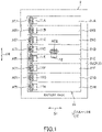
- FIG. 1 is a top view of a battery monitoring device 1 of the present invention mounted on a battery pack 2 in a first example.
- FIG. 2 is an electric block diagram of the battery monitoring apparatus 1 shown in FIG. 1 .
- the battery monitoring device 1 is a device that monitors a state of the battery pack 2 mounted on a vehicle (not shown).
- a vehicle is a vehicle that travels by a driving force from an electric motor, such as a hybrid car or an electric car.
- the battery pack 2 supplies power to the electric motor mounted on the vehicle.
- the battery pack 2 includes: a battery 21 composed of a plurality of battery modules 21A to 21H connected in series with each other; and a housing 22 for housing the battery 21.
- the plurality of battery modules 21A to 21H may be composed of a plurality of cells or may be composed of one cell.
- the plurality of battery modules 21A to 21H is provided in a box shape, and housed in the housing 22 in a line.
- a pair of electrodes (a positive electrode and a negative electrode) (not shown) is provided side by side in a width direction DI on an upper surface of each of the battery modules 21A to 21H.
- positive electrodes and negative electrodes are alternately arranged, and are connected in series by connecting electrodes of adjacent cells.
- the housing 22 includes: a housing body 212 whose upper surface is opened; and a lid (not shown) that covers the opening of the housing body 212.
- the plurality of battery modules 21A to 21H is accommodated in the housing body 212, and the upper surfaces of the battery modules 21A to 21H are covered with the lid (not shown).
- the battery monitoring device 1 is a device that monitors the state of the battery modules that constitute the battery pack 2, and includes: a plurality of detection boards 11A to 11H mounted respectively on the plurality of battery modules 21A to 21H; and one ECU board 12.
- a plurality of detection boards 11A to 11H mounted respectively on the plurality of battery modules 21A to 21H
- one ECU board 12 one ECU board 12.
- One detection board may be mounted on the plurality of battery modules 21A to 21H.
- each of the plurality of detection boards 11A to 11H includes: a detection circuit 111 that detects status information (cell voltage, cell temperature, etc.) of the battery module mounted thereon; a wireless circuit 112; and a first antenna ATI for wirelessly transmitting the status information of the battery module.
- the plurality of detection boards 11A to 11H is disposed on the top surfaces of the battery modules 21A to 21H. Further, the plurality of detection boards 11A to 11H is arranged in a line along an arrangement direction D2 of the battery modules 21A to 21H on one side in a width direction D1 of the upper surface of each of the battery modules 21A to 21H.
- the width direction D1 is a direction orthogonal to the arrangement direction D2 on the top surfaces of the battery modules 21A to 21H which are the same plane.
- each of the detection boards 11A to 11H is, for example, a long substrate, and a longitudinal direction thereof is disposed along the width direction D1.
- the first antenna AT1 is disposed at one end of each of the detection boards 11A to 11H in the longitudinal direction, and disposed on a side away from the ECU board 12. Incidentally, in the present embodiment, an example will be described in which the first antenna AT1 is disposed on the side away from the ECU board 12. The first antenna AT1 may be disposed on a side close to the ECU board 12.
- One ECU board 12 is provided for the plurality of detection boards 11A to 11H.
- a second antenna AT2 for receiving status information transmitted from the first antenna AT1 and an ECU 121 (monitoring unit) for monitoring and processing (cell abnormality detection processing, cell equalization processing, and the like) of the battery 21 based on the received status information are mounted on the ECU board 12.
- One (or many) second antenna AT2 is provided for the plurality of first antennas ATI.
- the ECU board 12 is disposed at the center of the upper surface of the battery 21 as shown in FIG. 1 .
- the ECU board 12 is disposed at the center in the width direction D1 and at the center in the line direction D2 of the battery 21 in top view.
- the ECU board 12 is separated from the plurality of detection boards 11A to 11H in the width direction D1.
- the ECU board 12 may be attached to the battery 21 and disposed on the upper surface of the battery 21, or may be attached to the lid (not shown) and disposed on the upper surface of the battery 21.
- the communication between the detection boards 11A to 11H and the ECU board 12 may be a direct method in which the detection boards 11A to 11H communicate with the ECU board 12 directly.
- a relay method may be used in which other adjacent detection boards 11A to 11H are relayed to communicate with the ECU board 12.
- the first antennas ATI mounted on each of the plurality of battery modules 21A to 21H are disposed on the same plane (upper surface) of the plurality of battery modules 21A to 21H, and the second antenna AT2 is disposed at the center in the arrangement direction D2.
- the first antennas AT1 of the other detection boards 11A to 11H are not arranged as much as possible in the communication path between the first antennas ATI of the detection boards 11A to 11H and the second antenna AT2 of the ECU board 12. Thereby, communication quality can be stabilized and improved.
- the plurality of first antennas AT1 is arranged in a line along the arrangement direction D2, and the plurality of first antennas ATI and the second antenna AT2 are separated in the width direction D1.
- the second antenna AT2 mounted on the ECU board 12 is disposed at the center of the upper surface of the battery 21 in the width direction D1.
- the second antenna AT2 may be disposed at the center of the arrangement direction D2 of the upper surface of the battery 21 and may not be disposed at the center of the width direction D1.
- the first antennas ATI mounted on the detection boards 11A to 11H are arranged in a line along the arrangement direction D2 .
- the second antenna AT2 may be disposed at the center in the arrangement direction D2 of the upper surface of the battery 21, and the first antennas AT1 may be mounted at any positions as long as they are mounted on the corresponding battery modules 21A to 21H.
- FIG. 3 components equivalent to components already described in the first embodiment described above with reference to FIG. 1 are assigned the same reference signs and detailed explanations thereof will be omitted.
- a significant difference between the first embodiment and the second embodiment is the arrangement positions of the plurality of detection boards 11A to 11H and the ECU board 12.
- the ECU board 12 is disposed at the center in the arrangement direction D2 and at the center in the width direction D1 of the battery 21 in top view.
- the ECU board 12 may be mounted on the battery 21 and disposed on the upper surface of the battery 21, or may be mounted on the lid (not shown) and disposed on the upper surface of the battery 21.
- the plurality of detection boards 11A to 11H is disposed on the top surfaces of the battery modules 21A to 21H.
- the detection boards 11A, 11C, 11E, and 11G disposed at odd-numbered positions from one side (upper side in the drawing) in the arrangement direction D2 are disposed on one side (right side in the drawing) in the width direction with respect to the ECU board 12 in a line along the arrangement direction D2.
- the detection boards 11B, 11D, 11F, and 11H disposed on even-numbered positions from the one side in the arrangement direction D2 are disposed on another side in the width direction D1 (left side in the drawing) with respect to the ECU board 12 in a line along the arrangement direction D2.
- each of the detection boards 11A to 11H is, for example, a long substrate, and arranged such that a longitudinal direction thereof is along the width direction D1.
- the first antenna AT1 is disposed at one end of each of the detection boards 11A to 11H in the longitudinal direction, and the one end is disposed toward the ECU board 12.
- the first antennas AT1 of the other detection boards 11A to 11H are not arranged as much as possible in the communication path between the first antennas AT1 of the detection boards 11A to 11H and the second antenna AT2 of the ECU board 12. Thereby, communication quality can be stabilized and improved.
- the first antennas AT1 of the other detection boards 11A to 11H are arranged as little as possible between the first antennas AT1 of the detection boards 11A to 11H and the first antennas AT1 of the detection boards 11A to 11H to be relayed. Thereby, communication quality can be stabilized and improved.
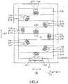
- FIG. 4 components equivalent to components already described in the first embodiment described above with reference to FIG. 1 are assigned the same reference signs and detailed explanations thereof will be omitted.
- a significant difference between the first embodiment and the third embodiment is the arrangement positions of the plurality of detection boards 11A to 11H and the ECU board 12.
- the ECU board 12 is disposed at the center in the arrangement direction D2 and at the center in the width direction D1 of the battery 21 in top view.
- the ECU board 12 may be mounted on the battery 21 and disposed on the upper surface of the battery 21, or may be mounted on the lid (not shown) and disposed on the upper surface of the battery 21.
- the plurality of detection boards 11A to 11H is disposed on the top surfaces of the battery modules 21A to 21H.
- the detection boards 11A and 11H mounted on the battery modules 21A and 21H disposed at both ends in the arrangement direction D2 are disposed at the center in the width direction D1 on the upper surface of the battery modules 21A and 21H.
- the detection boards 11B to 11G the detection boards 11C, 11E, and 11G disposed at odd-numbered positions from one side (upper side in the drawing) of the arrangement direction D2 are one side (right side in the drawing) in the width direction D1 with respect to the ECU board 12.
- the detection boards 11B, 11D and 11F disposed at even-numbered positions from the one side in the arrangement direction D2 are disposed on another side (left side in the drawing) in the width direction D1 with respect to the ECU board 12.
- the detection boards 11A to 11H mounted on the battery modules 21A to 21H closer to the center in the arrangement direction D2 are disposed at positions farther away from the center in the width direction D1.
- the first antenna AT1 mounted on the detection boards 11B, 11C, 11F, and 11G is arranged diagonally with respect to the width direction D1 and the arrangement direction D2 so that the direction of the first antenna AT1 faces the ECU board 12.
- the present invention is not limited to this.
- the directions of the first antennas AT1 mounted on the detection boards 11B, 11C, 11F, and 11G may be disposed, for example, parallel to the width direction D1 or the arrangement direction D2.
- each of the detection boards 11A to 11H is, for example, a long substrate, and the first antenna AT1 is disposed at one end of each of the detection boards 11A to 11H in the longitudinal direction.
- Each of the detection boards 11A to 11H is arranged such that one end on which the first antenna AT1 is mounted is disposed toward the ECU board 12. Thereby, communication quality can be stabilized and improved.
- the ECU board 12 can be disposed at the center of the upper surface of the battery 21, and the plurality of detection boards 11A to 11H can be disposed along a circle surrounding the ECU board 12. Then, the longitudinal direction of each of the detection boards 11A to 11H is disposed along a radial direction centering on the ECU board 12.
- the other detection boards are not arranged as much as possible in the communication path between the first antennas AT1 of the detection boards 11A to 11H and the second antenna AT2 of the ECU board 12.
- communication quality can be stabilized and improved.
- the distances between the first antennas AT1 of the detection boards 11A to 11H and the second antenna AT2 of the ECU board 12 can be further equalized as compared with the second embodiment, the communication quality can be further stabilized and improved.
- the first antennas AT1 of the other detection boards 11A to 11H are arranged as little as possible between the first antennas AT1 of the detection boards 11A to 11H and the first antennas AT1 of the detection boards 11A to 11H to be relayed. Thereby, communication quality can be stabilized and improved.
- the communication quality can be further stabilized and improved.
- FIG. 5 components equivalent to components already described in the third embodiment described above with reference to FIG. 4 are assigned the same reference signs and detailed explanations thereof will be omitted.
- a significant difference between the third embodiment and the modification is the configuration of the battery 21.
- the upper surface of the battery 21 is approximated to a square. Since the arrangement of the plurality of detection boards 11A to 11H and the ECU board 12 is the same as in the third embodiment, the detailed description is omitted here. Thus, by approximating the upper surface of the battery 21 to a square, the distances between the first antennas AT1 of the detection boards 11A to 11H and the second antenna AT2 of the ECU board 12, and the distances between the first antennas Al of the detection boards 11A to 11H and the first antennas Al of the other detection boards 11A to 11H can be further equalized, and communication quality can be stabilized and improved.
- FIGS. 6 to 8 components equivalent to components already described in the first example described above with reference to FIG. 1 are assigned the same reference signs and detailed explanations thereof will be omitted.
- a significant difference between the first example and the fourth example is the arrangement positions of the plurality of detection boards 11A to 11E and the ECU board 12.
- the battery 21 is configured of five battery modules 21A to 21E, and five detection boards 11A to 11E are mounted on the respective battery modules 21A to 21E.
- the plurality of detection boards 11A to 11E is disposed on the upper surfaces (xy plane) of the plurality of battery modules 21A to 2IE. Further, as shown in FIG. 7 , the plurality of detection boards 11A to 11E is disposed along a direction in which the directivity of the first antenna AT1 is the strongest on the xy plane. In the present embodiment, the direction in which the directivity of the first antenna AT1 is the strongest in the xy plane is parallel to the arrangement direction D2, and the plurality of detection boards 11A to 11E is arranged in a line along the arrangement direction D2.
- the ECU board 12 and the detection board 11C disposed at the center among the plurality of detection boards 11A to 11E are disposed opposite to each other in a direction in which the directivity of the first antenna AT1 and the second antenna AT2 is the strongest on the yz plane orthogonal to the xy plane.
- the direction in which the directivity of the first antenna AT1 and the second antenna AT2 is the strongest in the yz plane is a height direction D3
- the detection board 11C and the ECU board 12 are provided opposite to each other in the height direction D3.
- the height direction D3 is the z-axis direction of the yz plane, and is a direction orthogonal to both the width direction D1 and the arrangement direction D2.
- first antenna AT1 and the second antenna AT2 are disposed opposite to each other in the direction in which the directivity is the strongest on the yz plane.
- first antenna AT1 and the second antenna AT2 may be disposed opposed to each other in the direction in which the directivity is strongest on the xz plane.
- the communication method in the fourth example described above adopts, for example, direct communication between the detection boards 11A to 11H and the ECU board 12 as in the first embodiment. If direct communication cannot be performed (at the time of abnormality), the detection boards 11A to 11H may communicate with the ECU board 12 via another detection board. Alternatively, the detection boards 11A to 11H may be basically relayed to the detection board 11C with the first antenna ATI having the strongest directivity. In the example of the fourth example, detection boards 11A to 11H may be relayed to the detection board 11C having the strongest directivity with the ECU board 12.
- the plurality of first antennas AT1 are arranged along the direction in which the directivity of the first antenna AT1 is the strongest (arrangement direction D2) on the top surfaces of the plurality of battery modules 21A to 21E.
- the second antenna AT2 and the first antenna AT1 of the detection board 11C among the plurality of detection boards are disposed opposite to the direction in which the directivity of the first antenna AT1 and the second antenna AT2 is the strongest (height direction D3) on the yz plane.
- the ECU board 12 is disposed opposite to the detection board 11C, but the present invention is not limited to this.
- the ECU board 12 may be disposed opposite to one of the detection boards 11A to 11E, and may be disposed opposite to any one of the detection boards 11A, 11B, 11D, and 11E.
- the ECU board 12 is provided on the lid 222, but the present invention is not limited to this.
- the ECU board 12 is disposed on the side surface of the battery modules 21A to 21E.
- the second antenna AT2 and the first antenna AT1 of at least one of the detection boards 11A to 11E are disposed such that the directivity may be enhanced.
Landscapes
- Engineering & Computer Science (AREA)
- Manufacturing & Machinery (AREA)
- Chemical & Material Sciences (AREA)
- Chemical Kinetics & Catalysis (AREA)
- Electrochemistry (AREA)
- General Chemical & Material Sciences (AREA)
- Microelectronics & Electronic Packaging (AREA)
- Physics & Mathematics (AREA)
- General Physics & Mathematics (AREA)
- Computer Networks & Wireless Communication (AREA)
- Secondary Cells (AREA)
- Tests Of Electric Status Of Batteries (AREA)
- Battery Mounting, Suspending (AREA)
- Charge And Discharge Circuits For Batteries Or The Like (AREA)
Description
- The present invention relates to a battery monitoring device.
- As a battery monitoring device for monitoring the state of a battery having a plurality of cells or a single cell, for example, those shown in
Patent Literatures Patent Literatures - In
Patent Literatures - Therefore, it is desirable that only one second antenna can be mounted on the ECU to receive information from a plurality of detection units. However, depending on the arrangement of the detection unit and the ECU, another detection unit may be arranged on the communication path between the ECU and the detection unit, which may hinder the communication. Also, when communication cannot be made directly from the detection unit to the ECU, communication with the ECU via another detection unit (relay unit) is also conceivable. However, even in such a case, another detection unit may be disposed between the detection unit and the relay unit, which may hinder communication.
-
- Patent Literature 1:
JP 2016-157681 A - Patent Literature 2:
JP 2012-85491 A - Patent Literature 3:
US 2015/028816 A1 - Patent Literature 4:
US 2016/247389 A1 -
US 2015/028816 A1 relates to a wireless battery area network. A slave battery management unit (S-BMU), mounted on each of a plurality of battery cells, is wirelessly connected to a single master battery management unit (M-BMU). -
US 2016/247389 A1 relates to a battery monitoring device for monitoring a plurality of batteries. For each battery, there is a first antenna that transmits state information of the battery and a second antenna that receives the status information of the battery. - The invention is defined in the appended claims.
- The present invention has been made in view of the above background, and an object of the present invention is to provide a battery monitoring device in which communication quality is stabilized and improved.
- As described above, according to these aspects, the communication quality can be stabilized and improved.
-
-
FIG. 1 is a top view of a battery monitoring device mounted on a battery pack in a first example; -
FIG. 2 is an electric block diagram of the battery monitoring apparatus shown inFIG. 1 ; -
FIG. 3 is a top view of the battery monitoring device in a second embodiment; -
FIG. 4 is a top view of the battery monitoring device in a third embodiment; -
FIG. 5 is a top view of the battery monitoring device in a modification of the third embodiment; -
FIG. 6 is an exploded perspective view of the battery monitoring device in a fourth example; -
FIG. 7 is a top view ofFIG. 6 ; -
FIG. 8 is a side view ofFIG. 6 ; and -
FIG. 9 is a side view of the battery monitoring device. -
FIG. 1 is a top view of abattery monitoring device 1 of the present invention mounted on abattery pack 2 in a first example.FIG. 2 is an electric block diagram of thebattery monitoring apparatus 1 shown inFIG. 1 . Thebattery monitoring device 1 is a device that monitors a state of thebattery pack 2 mounted on a vehicle (not shown). Such a vehicle is a vehicle that travels by a driving force from an electric motor, such as a hybrid car or an electric car. Thebattery pack 2 supplies power to the electric motor mounted on the vehicle. - The
battery pack 2 includes: abattery 21 composed of a plurality ofbattery modules 21A to 21H connected in series with each other; and ahousing 22 for housing thebattery 21. The plurality ofbattery modules 21A to 21H may be composed of a plurality of cells or may be composed of one cell. The plurality ofbattery modules 21A to 21H is provided in a box shape, and housed in thehousing 22 in a line. A pair of electrodes (a positive electrode and a negative electrode) (not shown) is provided side by side in a width direction DI on an upper surface of each of thebattery modules 21A to 21H. In the cells constituting thebattery modules 21A to 21H, positive electrodes and negative electrodes are alternately arranged, and are connected in series by connecting electrodes of adjacent cells. - The
housing 22 includes: ahousing body 212 whose upper surface is opened; and a lid (not shown) that covers the opening of thehousing body 212. The plurality ofbattery modules 21A to 21H is accommodated in thehousing body 212, and the upper surfaces of thebattery modules 21A to 21H are covered with the lid (not shown). - The
battery monitoring device 1 is a device that monitors the state of the battery modules that constitute thebattery pack 2, and includes: a plurality ofdetection boards 11A to 11H mounted respectively on the plurality ofbattery modules 21A to 21H; and oneECU board 12. Incidentally, in the present example, an example in which the plurality ofdetection boards 11A to 11H are mounted on the plurality ofbattery modules 21A to 21H will be described, but the present invention is not limited to this. One detection board may be mounted on the plurality ofbattery modules 21A to 21H. - The plurality of
detection boards 11A to 11H is provided one by one with respect to thebattery modules 21A to 21H, and one of thedetection boards 11A to 11H is mounted on one of thebattery modules 21A to 21H. As shown inFIG. 2 , each of the plurality ofdetection boards 11A to 11H includes: adetection circuit 111 that detects status information (cell voltage, cell temperature, etc.) of the battery module mounted thereon; awireless circuit 112; and a first antenna ATI for wirelessly transmitting the status information of the battery module. - In the first example, as shown in
FIG. 1 , the plurality ofdetection boards 11A to 11H is disposed on the top surfaces of thebattery modules 21A to 21H. Further, the plurality ofdetection boards 11A to 11H is arranged in a line along an arrangement direction D2 of thebattery modules 21A to 21H on one side in a width direction D1 of the upper surface of each of thebattery modules 21A to 21H. Incidentally, the width direction D1 is a direction orthogonal to the arrangement direction D2 on the top surfaces of thebattery modules 21A to 21H which are the same plane. Further, each of thedetection boards 11A to 11H is, for example, a long substrate, and a longitudinal direction thereof is disposed along the width direction D1. The first antenna AT1 is disposed at one end of each of thedetection boards 11A to 11H in the longitudinal direction, and disposed on a side away from theECU board 12. Incidentally, in the present embodiment, an example will be described in which the first antenna AT1 is disposed on the side away from theECU board 12. The first antenna AT1 may be disposed on a side close to theECU board 12. - One
ECU board 12 is provided for the plurality ofdetection boards 11A to 11H. As shown inFIG. 2 , a second antenna AT2 for receiving status information transmitted from the first antenna AT1 and an ECU 121 (monitoring unit) for monitoring and processing (cell abnormality detection processing, cell equalization processing, and the like) of thebattery 21 based on the received status information are mounted on theECU board 12. One (or many) second antenna AT2 is provided for the plurality of first antennas ATI. - The
ECU board 12 is disposed at the center of the upper surface of thebattery 21 as shown inFIG. 1 . In detail, theECU board 12 is disposed at the center in the width direction D1 and at the center in the line direction D2 of thebattery 21 in top view. As a result, theECU board 12 is separated from the plurality ofdetection boards 11A to 11H in the width direction D1. TheECU board 12 may be attached to thebattery 21 and disposed on the upper surface of thebattery 21, or may be attached to the lid (not shown) and disposed on the upper surface of thebattery 21. - Incidentally, the communication between the
detection boards 11A to 11H and theECU board 12 may be a direct method in which thedetection boards 11A to 11H communicate with theECU board 12 directly. In addition, when each of thedetection boards 11A to 11H cannot directly communicate with theECU board 12, a relay method may be used in which otheradjacent detection boards 11A to 11H are relayed to communicate with theECU board 12. - According to the first example described above, the first antennas ATI mounted on each of the plurality of
battery modules 21A to 21H are disposed on the same plane (upper surface) of the plurality ofbattery modules 21A to 21H, and the second antenna AT2 is disposed at the center in the arrangement direction D2. Thus, the first antennas AT1 of theother detection boards 11A to 11H are not arranged as much as possible in the communication path between the first antennas ATI of thedetection boards 11A to 11H and the second antenna AT2 of theECU board 12. Thereby, communication quality can be stabilized and improved. - Further, according to the first example described above, the plurality of first antennas AT1 is arranged in a line along the arrangement direction D2, and the plurality of first antennas ATI and the second antenna AT2 are separated in the width direction D1. Thereby, even if the mounting position of the first antenna AT1 in each of the
battery modules 21A to 21H is the same, the first antennas AT1 of theother detection boards 11A to 11H can be arranged as little as possible along the communication path between the first antenna AT1 of each of thedetection boards 11A to 11H and the second antenna AT2 of theECU board 12. - Incidentally, according to the first example described above, the second antenna AT2 mounted on the
ECU board 12 is disposed at the center of the upper surface of thebattery 21 in the width direction D1. However, the present invention is not limited to this. The second antenna AT2 may be disposed at the center of the arrangement direction D2 of the upper surface of thebattery 21 and may not be disposed at the center of the width direction D1. - Further, according to the first example described above, the first antennas ATI mounted on the
detection boards 11A to 11H are arranged in a line along the arrangement direction D2 . The second antenna AT2 may be disposed at the center in the arrangement direction D2 of the upper surface of thebattery 21, and the first antennas AT1 may be mounted at any positions as long as they are mounted on thecorresponding battery modules 21A to 21H. - Next, a battery monitoring device according to a second embodiment will be described with reference to
FIG. 3 . InFIG. 3 , components equivalent to components already described in the first embodiment described above with reference toFIG. 1 are assigned the same reference signs and detailed explanations thereof will be omitted. A significant difference between the first embodiment and the second embodiment is the arrangement positions of the plurality ofdetection boards 11A to 11H and theECU board 12. - In the second embodiment, the
ECU board 12 is disposed at the center in the arrangement direction D2 and at the center in the width direction D1 of thebattery 21 in top view. TheECU board 12 may be mounted on thebattery 21 and disposed on the upper surface of thebattery 21, or may be mounted on the lid (not shown) and disposed on the upper surface of thebattery 21. - Further, in the second embodiment, as shown in
FIG. 3 , the plurality ofdetection boards 11A to 11H is disposed on the top surfaces of thebattery modules 21A to 21H. Among the plurality ofdetection boards 11A to 11H, thedetection boards ECU board 12 in a line along the arrangement direction D2. On the other hand, among the plurality ofdetection boards 11A to 11H, thedetection boards ECU board 12 in a line along the arrangement direction D2. - Further, each of the
detection boards 11A to 11H is, for example, a long substrate, and arranged such that a longitudinal direction thereof is along the width direction D1. The first antenna AT1 is disposed at one end of each of thedetection boards 11A to 11H in the longitudinal direction, and the one end is disposed toward theECU board 12. - According to the embodiment described above, the first antennas AT1 of the
other detection boards 11A to 11H are not arranged as much as possible in the communication path between the first antennas AT1 of thedetection boards 11A to 11H and the second antenna AT2 of theECU board 12. Thereby, communication quality can be stabilized and improved. - In addition, even when the communication between the first antenna AT1 of each of the
detection boards 11A to 11H and the second antenna AT2 of theECU board 12 is a relay system, the first antennas AT1 of theother detection boards 11A to 11H are arranged as little as possible between the first antennas AT1 of thedetection boards 11A to 11H and the first antennas AT1 of thedetection boards 11A to 11H to be relayed. Thereby, communication quality can be stabilized and improved. - Next, a battery monitoring device according to a third embodiment will be described with reference to
FIG. 4 . InFIG. 4 , components equivalent to components already described in the first embodiment described above with reference toFIG. 1 are assigned the same reference signs and detailed explanations thereof will be omitted. A significant difference between the first embodiment and the third embodiment is the arrangement positions of the plurality ofdetection boards 11A to 11H and theECU board 12. - In the third embodiment, the
ECU board 12 is disposed at the center in the arrangement direction D2 and at the center in the width direction D1 of thebattery 21 in top view. TheECU board 12 may be mounted on thebattery 21 and disposed on the upper surface of thebattery 21, or may be mounted on the lid (not shown) and disposed on the upper surface of thebattery 21. - Further, in the third embodiment, as shown in
FIG. 4 , the plurality ofdetection boards 11A to 11H is disposed on the top surfaces of thebattery modules 21A to 21H. Among the plurality ofdetection boards 11A to 11H, thedetection boards battery modules battery modules - Further, among the remaining
detection boards 11B to 11G, thedetection boards ECU board 12. On the other hand, among the remainingdetection boards 11B to 11G, thedetection boards ECU board 12. Further, thedetection boards 11A to 11H mounted on thebattery modules 21A to 21H closer to the center in the arrangement direction D2 are disposed at positions farther away from the center in the width direction D1. Incidentally, in the present embodiment, as shown inFIGS. 4 and5 , the first antenna AT1 mounted on thedetection boards ECU board 12. However, the present invention is not limited to this. The directions of the first antennas AT1 mounted on thedetection boards - Further, each of the
detection boards 11A to 11H is, for example, a long substrate, and the first antenna AT1 is disposed at one end of each of thedetection boards 11A to 11H in the longitudinal direction. Each of thedetection boards 11A to 11H is arranged such that one end on which the first antenna AT1 is mounted is disposed toward theECU board 12. Thereby, communication quality can be stabilized and improved. - As a result, as shown in
FIG. 4 , theECU board 12 can be disposed at the center of the upper surface of thebattery 21, and the plurality ofdetection boards 11A to 11H can be disposed along a circle surrounding theECU board 12. Then, the longitudinal direction of each of thedetection boards 11A to 11H is disposed along a radial direction centering on theECU board 12. - According to the third embodiment, the other detection boards are not arranged as much as possible in the communication path between the first antennas AT1 of the
detection boards 11A to 11H and the second antenna AT2 of theECU board 12. Thereby, communication quality can be stabilized and improved. Moreover, since the distances between the first antennas AT1 of thedetection boards 11A to 11H and the second antenna AT2 of theECU board 12 can be further equalized as compared with the second embodiment, the communication quality can be further stabilized and improved. - In addition, even when the communication between each of the
detection boards 11A to 11H and theECU board 12 is a relay system, the first antennas AT1 of theother detection boards 11A to 11H are arranged as little as possible between the first antennas AT1 of thedetection boards 11A to 11H and the first antennas AT1 of thedetection boards 11A to 11H to be relayed. Thereby, communication quality can be stabilized and improved. In addition, since the distances between the first antennas AT1 of thedetection boards 11A to 11H and the first antennas AT1 of theother detection boards 11A to 11H can be equalized, the communication quality can be further stabilized and improved. - Next, a modification of the third embodiment will be described with reference to
FIG. 5 . InFIG. 5 , components equivalent to components already described in the third embodiment described above with reference toFIG. 4 are assigned the same reference signs and detailed explanations thereof will be omitted. A significant difference between the third embodiment and the modification is the configuration of thebattery 21. - As shown in the figure, the upper surface of the
battery 21 is approximated to a square. Since the arrangement of the plurality ofdetection boards 11A to 11H and theECU board 12 is the same as in the third embodiment, the detailed description is omitted here. Thus, by approximating the upper surface of thebattery 21 to a square, the distances between the first antennas AT1 of thedetection boards 11A to 11H and the second antenna AT2 of theECU board 12, and the distances between the first antennas Al of thedetection boards 11A to 11H and the first antennas Al of theother detection boards 11A to 11H can be further equalized, and communication quality can be stabilized and improved. - Next, a battery monitoring device according to a fourth example will be described with reference to
FIGS. 6 to 8 . InFIGS. 6 to 8 , components equivalent to components already described in the first example described above with reference toFIG. 1 are assigned the same reference signs and detailed explanations thereof will be omitted. A significant difference between the first example and the fourth example is the arrangement positions of the plurality ofdetection boards 11A to 11E and theECU board 12. Moreover, in the present example, unlike the first example and the second to third embodiments, thebattery 21 is configured of fivebattery modules 21A to 21E, and fivedetection boards 11A to 11E are mounted on therespective battery modules 21A to 21E. - The plurality of
detection boards 11A to 11E is disposed on the upper surfaces (xy plane) of the plurality ofbattery modules 21A to 2IE. Further, as shown inFIG. 7 , the plurality ofdetection boards 11A to 11E is disposed along a direction in which the directivity of the first antenna AT1 is the strongest on the xy plane. In the present embodiment, the direction in which the directivity of the first antenna AT1 is the strongest in the xy plane is parallel to the arrangement direction D2, and the plurality ofdetection boards 11A to 11E is arranged in a line along the arrangement direction D2. - As shown in
FIG. 8 , theECU board 12 and thedetection board 11C disposed at the center among the plurality ofdetection boards 11A to 11E are disposed opposite to each other in a direction in which the directivity of the first antenna AT1 and the second antenna AT2 is the strongest on the yz plane orthogonal to the xy plane. In the present example, the direction in which the directivity of the first antenna AT1 and the second antenna AT2 is the strongest in the yz plane is a height direction D3, and thedetection board 11C and theECU board 12 are provided opposite to each other in the height direction D3. Incidentally, the height direction D3 is the z-axis direction of the yz plane, and is a direction orthogonal to both the width direction D1 and the arrangement direction D2. In the present embodiment, an example is shown in which the first antenna AT1 and the second antenna AT2 are disposed opposite to each other in the direction in which the directivity is the strongest on the yz plane. However, the first antenna AT1 and the second antenna AT2 may be disposed opposed to each other in the direction in which the directivity is strongest on the xz plane. - The communication method in the fourth example described above adopts, for example, direct communication between the
detection boards 11A to 11H and theECU board 12 as in the first embodiment. If direct communication cannot be performed (at the time of abnormality), thedetection boards 11A to 11H may communicate with theECU board 12 via another detection board. Alternatively, thedetection boards 11A to 11H may be basically relayed to thedetection board 11C with the first antenna ATI having the strongest directivity. In the example of the fourth example,detection boards 11A to 11H may be relayed to thedetection board 11C having the strongest directivity with theECU board 12. - According to the fourth example described above, the plurality of first antennas AT1 are arranged along the direction in which the directivity of the first antenna AT1 is the strongest (arrangement direction D2) on the top surfaces of the plurality of
battery modules 21A to 21E. The second antenna AT2 and the first antenna AT1 of thedetection board 11C among the plurality of detection boards are disposed opposite to the direction in which the directivity of the first antenna AT1 and the second antenna AT2 is the strongest (height direction D3) on the yz plane. Thereby, the radio wave strength between the first antennas AT1 of thedetection boards 11A to 11E and between the first antenna AT1 of thedetection board 11C and the second antenna AT2 of theECU board 12 can be increased, and the communication quality can be stabilized and improved. - Incidentally, according to the fourth example described above, the
ECU board 12 is disposed opposite to thedetection board 11C, but the present invention is not limited to this. TheECU board 12 may be disposed opposite to one of thedetection boards 11A to 11E, and may be disposed opposite to any one of thedetection boards - Further, according to the first example, the second embodiment, the third embodiment and the fourth example described above, the
ECU board 12 is provided on thelid 222, but the present invention is not limited to this. For example, as shown inFIG. 9 , theECU board 12 is disposed on the side surface of thebattery modules 21A to 21E. Then, the second antenna AT2 and the first antenna AT1 of at least one of thedetection boards 11A to 11E (for example, thedetection board 11C) are disposed such that the directivity may be enhanced. - Incidentally, the present invention is not limited to the above embodiment. That is, various modifications can be made without departing from the scope of the present invention from the scope of the present invention as defined in the appended claims.
-
- 1
- battery monitoring device
- 11A - IIH
- detection board
- 121
- ECU (monitoring unit)
- 21A - 21H
- battery module
- 111
- detection circuit
- ATI
- first antenna
- AT2
- second antenna
- DI
- width direction (orthogonal direction)
- D2
- arrangement direction
Claims (3)
- A battery monitoring device comprising:a plurality of battery modules arranged in a line;a plurality of first antennas (AT1) respectively mounted on the plurality of battery modules and wirelessly transmitting status information of the battery modules;a second antenna (AT2) for receiving the status information transmitted from the first antennas (AT1); anda monitoring unit that monitors the plurality of battery modules based on the status information received by the second antenna (AT2),wherein the plurality of first antennas (AT1) is mounted on a same plane, andwherein the second antenna (AT2) is disposed at the center in an arrangement direction (D2) of the battery modules,wherein the second antenna (AT2) is disposed at the center in an orthogonal direction (D1) orthogonal to the arrangement direction (D2) in plain view,wherein among the plurality of first antennas (AT1), the first antennas (AT1) disposed a odd-numbered positions from one side in the arrangement direction (D2) are disposed on one side in the orthogonal direction (D1) with respect to the second antenna (AT2), andwherein among the plurality of first antennas (AT1), the first antennas (AT1) disposed a even-numbered positions from the one side in the arrangement direction (D2) are disposed on another side in the orthogonal direction (D1) with respect to the second antenna (AT2).
- A battery monitoring device comprising:a plurality of battery modules arranged in a line;a plurality of first antennas (AT1) respectively mounted on the plurality of battery modules and wirelessly transmitting status information of the battery modules;a second antenna (AT2) for receiving the status information transmitted from the first antennas (AT1); anda monitoring unit that monitors the plurality of battery modules based on the status information received by the second antenna (AT2),wherein the plurality of first antennas (AT1) is mounted on a same plane, andwherein the second antenna (AT2) is disposed at the center in an arrangement direction (D2) of the battery modules,wherein the second antenna (AT2) and the first antennas (AT1) mounted on the battery modules arranged at both ends in the arrangement direction (D2) are disposed at the center in an orthogonal direction (D1) orthogonal to the arrangement direction (D2) in plain view,wherein among the first antennas (AT1) that are not mounted on the battery modules arranged at both ends in the arrangement direction, the first antennas (AT1) disposed at odd-numbered positions from one side in the arrangement direction (D2) are disposed on one side in the orthogonal direction (D1) with respect to the second antenna (AT2),wherein among the first antennas (AT1) that are not mounted on the battery modules arranged at both ends in the arrangement direction, the first antennas (AT1) disposed at even-numbered positions from the one side in the arrangement direction (D2) are disposed on another side in the orthogonal direction (D1) with respect to the second antenna (AT2), andwherein the first antennas (AT1) mounted on the battery modules closer to the center in the arrangement direction (D2) are disposed at positions farther from the center in the orthogonal direction (D1).
- The battery monitoring device as claimed in any one of claims 1 to 2,wherein the first antennas (AT1) are mounted on ends of detection boards, andwherein the detection boards are disposed such that the ends on which the first antennas (AT1) are mounted are directed to the second antenna (AT2).
Applications Claiming Priority (1)
| Application Number | Priority Date | Filing Date | Title |
|---|---|---|---|
| JP2018152623A JP6845830B2 (en) | 2018-08-14 | 2018-08-14 | Battery monitoring device |
Publications (2)
| Publication Number | Publication Date |
|---|---|
| EP3611789A1 EP3611789A1 (en) | 2020-02-19 |
| EP3611789B1 true EP3611789B1 (en) | 2022-09-07 |
Family
ID=67438134
Family Applications (1)
| Application Number | Title | Priority Date | Filing Date |
|---|---|---|---|
| EP19187237.3A Active EP3611789B1 (en) | 2018-08-14 | 2019-07-19 | Battery monitoring device |
Country Status (4)
| Country | Link |
|---|---|
| US (1) | US10950922B2 (en) |
| EP (1) | EP3611789B1 (en) |
| JP (1) | JP6845830B2 (en) |
| CN (1) | CN110828914B (en) |
Families Citing this family (6)
| Publication number | Priority date | Publication date | Assignee | Title |
|---|---|---|---|---|
| JP7347224B2 (en) | 2020-01-15 | 2023-09-20 | 株式会社デンソー | Communications system |
| JP7516808B2 (en) * | 2020-03-30 | 2024-07-17 | 株式会社デンソー | Communication system and communication device |
| JP7649665B2 (en) * | 2021-03-11 | 2025-03-21 | プライムプラネットエナジー&ソリューションズ株式会社 | Energy storage cell |
| JP7548166B2 (en) * | 2021-08-31 | 2024-09-10 | 株式会社デンソー | Battery Monitoring System |
| JPWO2023210652A1 (en) * | 2022-04-27 | 2023-11-02 | ||
| JP7658334B2 (en) * | 2022-06-17 | 2025-04-08 | 株式会社デンソー | Battery monitoring system, battery monitoring device, battery control device |
Family Cites Families (9)
| Publication number | Priority date | Publication date | Assignee | Title |
|---|---|---|---|---|
| JP4929389B2 (en) | 2010-10-14 | 2012-05-09 | 三菱重工業株式会社 | Battery system |
| US9564762B2 (en) * | 2010-11-02 | 2017-02-07 | Navitas Solutions | Fault tolerant wireless battery area network for a smart battery management system |
| US9559530B2 (en) | 2010-11-02 | 2017-01-31 | Navitas Solutions | Fault tolerant wireless battery area network for a smart battery management system |
| WO2013051157A1 (en) * | 2011-10-07 | 2013-04-11 | 日立ビークルエナジー株式会社 | Battery monitoring system, host controller, and battery monitoring device |
| JP2014197805A (en) * | 2013-03-29 | 2014-10-16 | 日立オートモティブシステムズ株式会社 | Battery system |
| JP6630156B2 (en) | 2015-02-19 | 2020-01-15 | 矢崎総業株式会社 | Battery monitoring device |
| JP6819233B2 (en) * | 2016-11-17 | 2021-01-27 | 株式会社オートネットワーク技術研究所 | Battery monitoring system for vehicles |
| WO2018131338A1 (en) * | 2017-01-12 | 2018-07-19 | 株式会社日立製作所 | Wireless battery system |
| JP2019082399A (en) * | 2017-10-30 | 2019-05-30 | ラピスセミコンダクタ株式会社 | Battery measuring device and battery monitoring system |
-
2018
- 2018-08-14 JP JP2018152623A patent/JP6845830B2/en active Active
-
2019
- 2019-07-10 US US16/507,447 patent/US10950922B2/en active Active
- 2019-07-17 CN CN201910645521.5A patent/CN110828914B/en active Active
- 2019-07-19 EP EP19187237.3A patent/EP3611789B1/en active Active
Also Published As
| Publication number | Publication date |
|---|---|
| JP6845830B2 (en) | 2021-03-24 |
| CN110828914A (en) | 2020-02-21 |
| US20200058980A1 (en) | 2020-02-20 |
| EP3611789A1 (en) | 2020-02-19 |
| US10950922B2 (en) | 2021-03-16 |
| JP2020027767A (en) | 2020-02-20 |
| CN110828914B (en) | 2023-03-21 |
Similar Documents
| Publication | Publication Date | Title |
|---|---|---|
| EP3611789B1 (en) | Battery monitoring device | |
| EP3828983B1 (en) | Battery module with icb assembly in a space-saving structure | |
| JP6630156B2 (en) | Battery monitoring device | |
| EP2388845B1 (en) | Battery pack | |
| US11539087B2 (en) | Vehicle energy-storage systems | |
| CN107438911B (en) | Battery module with improved fastening structure | |
| EP3193387B1 (en) | Battery cell interconnecting and voltage sensing assembly, and battery module | |
| JP7666490B2 (en) | Battery Module | |
| EP3651236A1 (en) | Battery module and battery pack comprising same | |
| EP3432409B1 (en) | Cell supervision circuit carrier, battery system and electric vehicle | |
| US11862817B2 (en) | Energy storage apparatus | |
| EP3226342B1 (en) | Cell connection unit | |
| JP2019126227A (en) | Battery monitoring system | |
| KR20170059226A (en) | Battery sensing module | |
| US11217848B2 (en) | Battery module, battery pack containing same, and use thereof | |
| CN111630690B (en) | Battery module, battery pack including the same, and application thereof | |
| KR20210122668A (en) | Battery system with light-based communication | |
| JP6573458B2 (en) | Sensor unit | |
| US20230395877A1 (en) | Battery Pack and Automobile Comprising Same | |
| EP3667760B1 (en) | Battery module | |
| EP4404342B1 (en) | Battery, electric device, and battery assembling method | |
| EP3890101A1 (en) | Battery pack comprising hv wire assembly, and method for manufacturing battery pack | |
| EP4557447A1 (en) | Wireless battery management system and battery pack including the same | |
| US20240258661A1 (en) | Battery Module and Battery Pack Comprising Same | |
| US20250379314A1 (en) | Structure and method for fixing battery module to battery pack |
Legal Events
| Date | Code | Title | Description |
|---|---|---|---|
| PUAI | Public reference made under article 153(3) epc to a published international application that has entered the european phase |
Free format text: ORIGINAL CODE: 0009012 |
|
| STAA | Information on the status of an ep patent application or granted ep patent |
Free format text: STATUS: REQUEST FOR EXAMINATION WAS MADE |
|
| 17P | Request for examination filed |
Effective date: 20190719 |
|
| AK | Designated contracting states |
Kind code of ref document: A1 Designated state(s): AL AT BE BG CH CY CZ DE DK EE ES FI FR GB GR HR HU IE IS IT LI LT LU LV MC MK MT NL NO PL PT RO RS SE SI SK SM TR |
|
| AX | Request for extension of the european patent |
Extension state: BA ME |
|
| RBV | Designated contracting states (corrected) |
Designated state(s): AL AT BE BG CH CY CZ DE DK EE ES FI FR GB GR HR HU IE IS IT LI LT LU LV MC MK MT NL NO PL PT RO RS SE SI SK SM TR |
|
| GRAP | Despatch of communication of intention to grant a patent |
Free format text: ORIGINAL CODE: EPIDOSNIGR1 |
|
| STAA | Information on the status of an ep patent application or granted ep patent |
Free format text: STATUS: GRANT OF PATENT IS INTENDED |
|
| INTG | Intention to grant announced |
Effective date: 20220225 |
|
| GRAJ | Information related to disapproval of communication of intention to grant by the applicant or resumption of examination proceedings by the epo deleted |
Free format text: ORIGINAL CODE: EPIDOSDIGR1 |
|
| STAA | Information on the status of an ep patent application or granted ep patent |
Free format text: STATUS: REQUEST FOR EXAMINATION WAS MADE |
|
| INTC | Intention to grant announced (deleted) | ||
| GRAP | Despatch of communication of intention to grant a patent |
Free format text: ORIGINAL CODE: EPIDOSNIGR1 |
|
| STAA | Information on the status of an ep patent application or granted ep patent |
Free format text: STATUS: GRANT OF PATENT IS INTENDED |
|
| INTG | Intention to grant announced |
Effective date: 20220512 |
|
| GRAS | Grant fee paid |
Free format text: ORIGINAL CODE: EPIDOSNIGR3 |
|
| GRAA | (expected) grant |
Free format text: ORIGINAL CODE: 0009210 |
|
| STAA | Information on the status of an ep patent application or granted ep patent |
Free format text: STATUS: THE PATENT HAS BEEN GRANTED |
|
| AK | Designated contracting states |
Kind code of ref document: B1 Designated state(s): AL AT BE BG CH CY CZ DE DK EE ES FI FR GB GR HR HU IE IS IT LI LT LU LV MC MK MT NL NO PL PT RO RS SE SI SK SM TR |
|
| REG | Reference to a national code |
Ref country code: GB Ref legal event code: FG4D |
|
| REG | Reference to a national code |
Ref country code: CH Ref legal event code: EP Ref country code: AT Ref legal event code: REF Ref document number: 1517809 Country of ref document: AT Kind code of ref document: T Effective date: 20220915 |
|
| REG | Reference to a national code |
Ref country code: IE Ref legal event code: FG4D |
|
| REG | Reference to a national code |
Ref country code: DE Ref legal event code: R096 Ref document number: 602019019170 Country of ref document: DE |
|
| REG | Reference to a national code |
Ref country code: LT Ref legal event code: MG9D |
|
| REG | Reference to a national code |
Ref country code: NL Ref legal event code: MP Effective date: 20220907 |
|
| PG25 | Lapsed in a contracting state [announced via postgrant information from national office to epo] |
Ref country code: SE Free format text: LAPSE BECAUSE OF FAILURE TO SUBMIT A TRANSLATION OF THE DESCRIPTION OR TO PAY THE FEE WITHIN THE PRESCRIBED TIME-LIMIT Effective date: 20220907 Ref country code: RS Free format text: LAPSE BECAUSE OF FAILURE TO SUBMIT A TRANSLATION OF THE DESCRIPTION OR TO PAY THE FEE WITHIN THE PRESCRIBED TIME-LIMIT Effective date: 20220907 Ref country code: NO Free format text: LAPSE BECAUSE OF FAILURE TO SUBMIT A TRANSLATION OF THE DESCRIPTION OR TO PAY THE FEE WITHIN THE PRESCRIBED TIME-LIMIT Effective date: 20221207 Ref country code: LV Free format text: LAPSE BECAUSE OF FAILURE TO SUBMIT A TRANSLATION OF THE DESCRIPTION OR TO PAY THE FEE WITHIN THE PRESCRIBED TIME-LIMIT Effective date: 20220907 Ref country code: LT Free format text: LAPSE BECAUSE OF FAILURE TO SUBMIT A TRANSLATION OF THE DESCRIPTION OR TO PAY THE FEE WITHIN THE PRESCRIBED TIME-LIMIT Effective date: 20220907 Ref country code: FI Free format text: LAPSE BECAUSE OF FAILURE TO SUBMIT A TRANSLATION OF THE DESCRIPTION OR TO PAY THE FEE WITHIN THE PRESCRIBED TIME-LIMIT Effective date: 20220907 |
|
| REG | Reference to a national code |
Ref country code: AT Ref legal event code: MK05 Ref document number: 1517809 Country of ref document: AT Kind code of ref document: T Effective date: 20220907 |
|
| PG25 | Lapsed in a contracting state [announced via postgrant information from national office to epo] |
Ref country code: HR Free format text: LAPSE BECAUSE OF FAILURE TO SUBMIT A TRANSLATION OF THE DESCRIPTION OR TO PAY THE FEE WITHIN THE PRESCRIBED TIME-LIMIT Effective date: 20220907 Ref country code: GR Free format text: LAPSE BECAUSE OF FAILURE TO SUBMIT A TRANSLATION OF THE DESCRIPTION OR TO PAY THE FEE WITHIN THE PRESCRIBED TIME-LIMIT Effective date: 20221208 |
|
| PG25 | Lapsed in a contracting state [announced via postgrant information from national office to epo] |
Ref country code: SM Free format text: LAPSE BECAUSE OF FAILURE TO SUBMIT A TRANSLATION OF THE DESCRIPTION OR TO PAY THE FEE WITHIN THE PRESCRIBED TIME-LIMIT Effective date: 20220907 Ref country code: RO Free format text: LAPSE BECAUSE OF FAILURE TO SUBMIT A TRANSLATION OF THE DESCRIPTION OR TO PAY THE FEE WITHIN THE PRESCRIBED TIME-LIMIT Effective date: 20220907 Ref country code: PT Free format text: LAPSE BECAUSE OF FAILURE TO SUBMIT A TRANSLATION OF THE DESCRIPTION OR TO PAY THE FEE WITHIN THE PRESCRIBED TIME-LIMIT Effective date: 20230109 Ref country code: ES Free format text: LAPSE BECAUSE OF FAILURE TO SUBMIT A TRANSLATION OF THE DESCRIPTION OR TO PAY THE FEE WITHIN THE PRESCRIBED TIME-LIMIT Effective date: 20220907 Ref country code: CZ Free format text: LAPSE BECAUSE OF FAILURE TO SUBMIT A TRANSLATION OF THE DESCRIPTION OR TO PAY THE FEE WITHIN THE PRESCRIBED TIME-LIMIT Effective date: 20220907 Ref country code: AT Free format text: LAPSE BECAUSE OF FAILURE TO SUBMIT A TRANSLATION OF THE DESCRIPTION OR TO PAY THE FEE WITHIN THE PRESCRIBED TIME-LIMIT Effective date: 20220907 |
|
| PG25 | Lapsed in a contracting state [announced via postgrant information from national office to epo] |
Ref country code: SK Free format text: LAPSE BECAUSE OF FAILURE TO SUBMIT A TRANSLATION OF THE DESCRIPTION OR TO PAY THE FEE WITHIN THE PRESCRIBED TIME-LIMIT Effective date: 20220907 Ref country code: PL Free format text: LAPSE BECAUSE OF FAILURE TO SUBMIT A TRANSLATION OF THE DESCRIPTION OR TO PAY THE FEE WITHIN THE PRESCRIBED TIME-LIMIT Effective date: 20220907 Ref country code: IS Free format text: LAPSE BECAUSE OF FAILURE TO SUBMIT A TRANSLATION OF THE DESCRIPTION OR TO PAY THE FEE WITHIN THE PRESCRIBED TIME-LIMIT Effective date: 20230107 Ref country code: EE Free format text: LAPSE BECAUSE OF FAILURE TO SUBMIT A TRANSLATION OF THE DESCRIPTION OR TO PAY THE FEE WITHIN THE PRESCRIBED TIME-LIMIT Effective date: 20220907 |
|
| REG | Reference to a national code |
Ref country code: DE Ref legal event code: R097 Ref document number: 602019019170 Country of ref document: DE |
|
| PG25 | Lapsed in a contracting state [announced via postgrant information from national office to epo] |
Ref country code: NL Free format text: LAPSE BECAUSE OF FAILURE TO SUBMIT A TRANSLATION OF THE DESCRIPTION OR TO PAY THE FEE WITHIN THE PRESCRIBED TIME-LIMIT Effective date: 20220907 Ref country code: AL Free format text: LAPSE BECAUSE OF FAILURE TO SUBMIT A TRANSLATION OF THE DESCRIPTION OR TO PAY THE FEE WITHIN THE PRESCRIBED TIME-LIMIT Effective date: 20220907 |
|
| PLBE | No opposition filed within time limit |
Free format text: ORIGINAL CODE: 0009261 |
|
| STAA | Information on the status of an ep patent application or granted ep patent |
Free format text: STATUS: NO OPPOSITION FILED WITHIN TIME LIMIT |
|
| PG25 | Lapsed in a contracting state [announced via postgrant information from national office to epo] |
Ref country code: DK Free format text: LAPSE BECAUSE OF FAILURE TO SUBMIT A TRANSLATION OF THE DESCRIPTION OR TO PAY THE FEE WITHIN THE PRESCRIBED TIME-LIMIT Effective date: 20220907 |
|
| 26N | No opposition filed |
Effective date: 20230608 |
|
| PG25 | Lapsed in a contracting state [announced via postgrant information from national office to epo] |
Ref country code: SI Free format text: LAPSE BECAUSE OF FAILURE TO SUBMIT A TRANSLATION OF THE DESCRIPTION OR TO PAY THE FEE WITHIN THE PRESCRIBED TIME-LIMIT Effective date: 20220907 |
|
| PG25 | Lapsed in a contracting state [announced via postgrant information from national office to epo] |
Ref country code: MC Free format text: LAPSE BECAUSE OF FAILURE TO SUBMIT A TRANSLATION OF THE DESCRIPTION OR TO PAY THE FEE WITHIN THE PRESCRIBED TIME-LIMIT Effective date: 20220907 |
|
| PG25 | Lapsed in a contracting state [announced via postgrant information from national office to epo] |
Ref country code: MC Free format text: LAPSE BECAUSE OF FAILURE TO SUBMIT A TRANSLATION OF THE DESCRIPTION OR TO PAY THE FEE WITHIN THE PRESCRIBED TIME-LIMIT Effective date: 20220907 |
|
| REG | Reference to a national code |
Ref country code: CH Ref legal event code: PL |
|
| REG | Reference to a national code |
Ref country code: BE Ref legal event code: MM Effective date: 20230731 |
|
| PG25 | Lapsed in a contracting state [announced via postgrant information from national office to epo] |
Ref country code: LU Free format text: LAPSE BECAUSE OF NON-PAYMENT OF DUE FEES Effective date: 20230719 |
|
| GBPC | Gb: european patent ceased through non-payment of renewal fee |
Effective date: 20230719 |
|
| PG25 | Lapsed in a contracting state [announced via postgrant information from national office to epo] |
Ref country code: LU Free format text: LAPSE BECAUSE OF NON-PAYMENT OF DUE FEES Effective date: 20230719 |
|
| REG | Reference to a national code |
Ref country code: IE Ref legal event code: MM4A |
|
| PG25 | Lapsed in a contracting state [announced via postgrant information from national office to epo] |
Ref country code: GB Free format text: LAPSE BECAUSE OF NON-PAYMENT OF DUE FEES Effective date: 20230719 Ref country code: CH Free format text: LAPSE BECAUSE OF NON-PAYMENT OF DUE FEES Effective date: 20230731 |
|
| PG25 | Lapsed in a contracting state [announced via postgrant information from national office to epo] |
Ref country code: IT Free format text: LAPSE BECAUSE OF FAILURE TO SUBMIT A TRANSLATION OF THE DESCRIPTION OR TO PAY THE FEE WITHIN THE PRESCRIBED TIME-LIMIT Effective date: 20220907 Ref country code: FR Free format text: LAPSE BECAUSE OF NON-PAYMENT OF DUE FEES Effective date: 20230731 Ref country code: BE Free format text: LAPSE BECAUSE OF NON-PAYMENT OF DUE FEES Effective date: 20230731 |
|
| PG25 | Lapsed in a contracting state [announced via postgrant information from national office to epo] |
Ref country code: IE Free format text: LAPSE BECAUSE OF NON-PAYMENT OF DUE FEES Effective date: 20230719 |
|
| PG25 | Lapsed in a contracting state [announced via postgrant information from national office to epo] |
Ref country code: IE Free format text: LAPSE BECAUSE OF NON-PAYMENT OF DUE FEES Effective date: 20230719 |
|
| PG25 | Lapsed in a contracting state [announced via postgrant information from national office to epo] |
Ref country code: BG Free format text: LAPSE BECAUSE OF FAILURE TO SUBMIT A TRANSLATION OF THE DESCRIPTION OR TO PAY THE FEE WITHIN THE PRESCRIBED TIME-LIMIT Effective date: 20220907 |
|
| PG25 | Lapsed in a contracting state [announced via postgrant information from national office to epo] |
Ref country code: BG Free format text: LAPSE BECAUSE OF FAILURE TO SUBMIT A TRANSLATION OF THE DESCRIPTION OR TO PAY THE FEE WITHIN THE PRESCRIBED TIME-LIMIT Effective date: 20220907 |
|
| PG25 | Lapsed in a contracting state [announced via postgrant information from national office to epo] |
Ref country code: CY Free format text: LAPSE BECAUSE OF FAILURE TO SUBMIT A TRANSLATION OF THE DESCRIPTION OR TO PAY THE FEE WITHIN THE PRESCRIBED TIME-LIMIT; INVALID AB INITIO Effective date: 20190719 |
|
| PG25 | Lapsed in a contracting state [announced via postgrant information from national office to epo] |
Ref country code: HU Free format text: LAPSE BECAUSE OF FAILURE TO SUBMIT A TRANSLATION OF THE DESCRIPTION OR TO PAY THE FEE WITHIN THE PRESCRIBED TIME-LIMIT; INVALID AB INITIO Effective date: 20190719 |
|
| PGFP | Annual fee paid to national office [announced via postgrant information from national office to epo] |
Ref country code: DE Payment date: 20250528 Year of fee payment: 7 |
|
| PG25 | Lapsed in a contracting state [announced via postgrant information from national office to epo] |
Ref country code: TR Free format text: LAPSE BECAUSE OF FAILURE TO SUBMIT A TRANSLATION OF THE DESCRIPTION OR TO PAY THE FEE WITHIN THE PRESCRIBED TIME-LIMIT Effective date: 20220907 |