EP3611566A1 - Projection system and projection method - Google Patents
Projection system and projection method Download PDFInfo
- Publication number
- EP3611566A1 EP3611566A1 EP17905978.7A EP17905978A EP3611566A1 EP 3611566 A1 EP3611566 A1 EP 3611566A1 EP 17905978 A EP17905978 A EP 17905978A EP 3611566 A1 EP3611566 A1 EP 3611566A1
- Authority
- EP
- European Patent Office
- Prior art keywords
- image data
- illumination light
- light
- luminous flux
- grayscale
- Prior art date
- Legal status (The legal status is an assumption and is not a legal conclusion. Google has not performed a legal analysis and makes no representation as to the accuracy of the status listed.)
- Granted
Links
Images




Classifications
-
- H—ELECTRICITY
- H04—ELECTRIC COMMUNICATION TECHNIQUE
- H04N—PICTORIAL COMMUNICATION, e.g. TELEVISION
- H04N9/00—Details of colour television systems
- H04N9/12—Picture reproducers
- H04N9/31—Projection devices for colour picture display, e.g. using electronic spatial light modulators [ESLM]
- H04N9/3141—Constructional details thereof
- H04N9/315—Modulator illumination systems
- H04N9/3152—Modulator illumination systems for shaping the light beam
-
- H—ELECTRICITY
- H04—ELECTRIC COMMUNICATION TECHNIQUE
- H04N—PICTORIAL COMMUNICATION, e.g. TELEVISION
- H04N9/00—Details of colour television systems
- H04N9/12—Picture reproducers
- H04N9/31—Projection devices for colour picture display, e.g. using electronic spatial light modulators [ESLM]
- H04N9/3141—Constructional details thereof
- H04N9/315—Modulator illumination systems
- H04N9/3155—Modulator illumination systems for controlling the light source
-
- G—PHYSICS
- G03—PHOTOGRAPHY; CINEMATOGRAPHY; ANALOGOUS TECHNIQUES USING WAVES OTHER THAN OPTICAL WAVES; ELECTROGRAPHY; HOLOGRAPHY
- G03B—APPARATUS OR ARRANGEMENTS FOR TAKING PHOTOGRAPHS OR FOR PROJECTING OR VIEWING THEM; APPARATUS OR ARRANGEMENTS EMPLOYING ANALOGOUS TECHNIQUES USING WAVES OTHER THAN OPTICAL WAVES; ACCESSORIES THEREFOR
- G03B21/00—Projectors or projection-type viewers; Accessories therefor
-
- G—PHYSICS
- G03—PHOTOGRAPHY; CINEMATOGRAPHY; ANALOGOUS TECHNIQUES USING WAVES OTHER THAN OPTICAL WAVES; ELECTROGRAPHY; HOLOGRAPHY
- G03B—APPARATUS OR ARRANGEMENTS FOR TAKING PHOTOGRAPHS OR FOR PROJECTING OR VIEWING THEM; APPARATUS OR ARRANGEMENTS EMPLOYING ANALOGOUS TECHNIQUES USING WAVES OTHER THAN OPTICAL WAVES; ACCESSORIES THEREFOR
- G03B21/00—Projectors or projection-type viewers; Accessories therefor
- G03B21/005—Projectors using an electronic spatial light modulator but not peculiar thereto
- G03B21/008—Projectors using an electronic spatial light modulator but not peculiar thereto using micromirror devices
-
- G—PHYSICS
- G03—PHOTOGRAPHY; CINEMATOGRAPHY; ANALOGOUS TECHNIQUES USING WAVES OTHER THAN OPTICAL WAVES; ELECTROGRAPHY; HOLOGRAPHY
- G03B—APPARATUS OR ARRANGEMENTS FOR TAKING PHOTOGRAPHS OR FOR PROJECTING OR VIEWING THEM; APPARATUS OR ARRANGEMENTS EMPLOYING ANALOGOUS TECHNIQUES USING WAVES OTHER THAN OPTICAL WAVES; ACCESSORIES THEREFOR
- G03B21/00—Projectors or projection-type viewers; Accessories therefor
- G03B21/14—Details
- G03B21/20—Lamp housings
-
- G—PHYSICS
- G03—PHOTOGRAPHY; CINEMATOGRAPHY; ANALOGOUS TECHNIQUES USING WAVES OTHER THAN OPTICAL WAVES; ELECTROGRAPHY; HOLOGRAPHY
- G03B—APPARATUS OR ARRANGEMENTS FOR TAKING PHOTOGRAPHS OR FOR PROJECTING OR VIEWING THEM; APPARATUS OR ARRANGEMENTS EMPLOYING ANALOGOUS TECHNIQUES USING WAVES OTHER THAN OPTICAL WAVES; ACCESSORIES THEREFOR
- G03B21/00—Projectors or projection-type viewers; Accessories therefor
- G03B21/14—Details
- G03B21/20—Lamp housings
- G03B21/2053—Intensity control of illuminating light
-
- G—PHYSICS
- G03—PHOTOGRAPHY; CINEMATOGRAPHY; ANALOGOUS TECHNIQUES USING WAVES OTHER THAN OPTICAL WAVES; ELECTROGRAPHY; HOLOGRAPHY
- G03B—APPARATUS OR ARRANGEMENTS FOR TAKING PHOTOGRAPHS OR FOR PROJECTING OR VIEWING THEM; APPARATUS OR ARRANGEMENTS EMPLOYING ANALOGOUS TECHNIQUES USING WAVES OTHER THAN OPTICAL WAVES; ACCESSORIES THEREFOR
- G03B21/00—Projectors or projection-type viewers; Accessories therefor
- G03B21/14—Details
- G03B21/20—Lamp housings
- G03B21/208—Homogenising, shaping of the illumination light
-
- H—ELECTRICITY
- H04—ELECTRIC COMMUNICATION TECHNIQUE
- H04N—PICTORIAL COMMUNICATION, e.g. TELEVISION
- H04N9/00—Details of colour television systems
- H04N9/12—Picture reproducers
- H04N9/31—Projection devices for colour picture display, e.g. using electronic spatial light modulators [ESLM]
- H04N9/3141—Constructional details thereof
- H04N9/315—Modulator illumination systems
- H04N9/3158—Modulator illumination systems for controlling the spectrum
-
- H—ELECTRICITY
- H04—ELECTRIC COMMUNICATION TECHNIQUE
- H04N—PICTORIAL COMMUNICATION, e.g. TELEVISION
- H04N9/00—Details of colour television systems
- H04N9/12—Picture reproducers
- H04N9/31—Projection devices for colour picture display, e.g. using electronic spatial light modulators [ESLM]
- H04N9/3179—Video signal processing therefor
Definitions
- the present disclosure relates to a projection system and a projection method.
- An existing projection system generally includes a light source device, a spatial light modulator (such as a LCOS spatial light modulator or a DMD spatial light modulator), and a projection lens.
- the light source device emits, for example, light of three colors of red, green and blue.
- the spatial light modulator image-modulates the light emitted by the light source device based on image data, and the projection lens projects image light output by the spatial light modulator to display a projection image.
- the existing projection system may have low contrast, which needs to be improved.
- the present disclosure provides a projection system and a projection method having relatively high contrast.
- a projection system includes:
- the signal processor receives the image data, the image data includes subframe image data, the signal processor determines whether a highest grayscale value of respective pixels in the subframe image data is smaller than a preset value, when the highest grayscale value of the respective pixels in the subframe image data is smaller than the preset value, the signal processor controls to increase the grayscale values of the respective pixels of the subframe image data, wherein a light emitting device adjusts the luminous flux of the illumination light to be smaller than standard luminous flux L O when the highest grayscale value of the respective pixels in the subframe image data is smaller than the preset value; and when the highest grayscale value of the respective pixels in the subframe image data is larger than or equal to the preset value, the signal processor keeps the grayscale values of the respective pixels of the subframe image data unchanged and provides the subframe image data to the DMD; the light emitting device emits illumination light of the standard luminous flux Lo, and the DMD modulates the illumination light of the standard luminous flux L O based on the subframe image data with the unchanged grayscale
- a grayscale maximum value that the projection system can reach is set to be G Max
- the preset value is set to be G R
- the preset value G R is smaller than or equal to the grayscale maximum value G Max .
- the preset value is set to be 90% of the grayscale maximum value G Max .
- the signal processor further calculates an adjustment coefficient k when the highest grayscale value of the respective pixels in the subframe image data is smaller than the preset value, the adjustment coefficient k is equal to G Max /G L , G L represents the highest grayscale value of the respective pixels in the subframe image data, the signal processor adjusts a grayscale value of each of the plurality of pixels of the image data to be k times the grayscale value of each of the pixels of the image data based on the adjustment coefficient k, and the luminous flux of the illumination light emitted by the light emitting device is adjusted to be 1/k of the standard luminous flux Lo.
- the adjusting member is configured to adjust the luminous flux of the illumination light emitted by the light source.
- the adjusting member is configured to reduce a divergence angle of the illumination light provided by the optical relay system, increase an F number of the illumination light provided by the optical relay system, and reduce the luminous flux of the illumination light provided by the optical relay system.
- the adjusting member includes an adjustable aperture, the adjustable aperture is disposed at an aperture stop of the optical relay system; the adjustable aperture is configured to block a peripheral portion of a light beam of the illumination light incident to the adjustable aperture, such that the illumination light exiting from the adjustable aperture has a smaller divergence angle, an increased F number, and a reduced luminous flux with respect to the illumination light incident to the adjustable aperture.
- the optical relay system includes a light homogenizing member configured to homogenize the illumination light;
- the adjusting member includes a liquid crystal lens located on an optical path prior to the light homogenizing member, wherein light exiting from the liquid crystal lens irradiates on an incident surface of the light homogenizing member; and the liquid crystal lens is configured to reduce the divergence angle of the illumination light, so that a cross sectional area of the illumination light, when being incident to a position of the incident surface of the light homogenizing member, is larger than an area of the incident surface, such that the illumination light entering the light homogenizing member has a reduced divergence angle, an increased F number, and reduced luminous flux.
- a projection method including steps of:
- the grayscale values of the plurality of pixels of the image data is increased; when a highest grayscale value of respective pixels in a subframe image data is larger than or equal to the preset value, grayscale values of the respective pixels of the subframe image data are kept unchanged, the luminous flux of the illumination light is controlled to be standard luminous flux Lo, and the illumination light of the standard luminous flux L O is modulated based on the image data with the unchanged grayscale values to generate the projection light required for the projection image.
- a grayscale maximum value that the projection system using the method can reach is set to be G Max
- the preset value is set to be G R
- the preset value G R is smaller than or equal to the grayscale maximum value G Max .
- the preset value is set to be 90% of the grayscale maximum value G Max .
- an adjustment coefficient k is calculated when the highest grayscale value of the respective pixels in the subframe image data is smaller than the preset value, wherein the adjustment coefficient k is equal to G Max /G L , and G L represents the highest grayscale value of the respective pixels in the subframe image data.
- a grayscale value of each of pixels of the image data is adjusted to be k times the grayscale value of each of the plurality of pixels of the image data based on the adjustment coefficient k, that is, a grayscale value of any one of the plurality of pixels of the image data is set to be Gi, and then an increased grayscale value corresponding to the grayscale value Gi of the pixel of the image data is k ⁇ Gi, and the luminous flux of the illumination light is adjusted to be 1/k of the standard luminous flux Lo and thus the luminous flux of the illumination light is L O /k.
- the grayscale values of the pixels of the image data are increased, and the luminous flux of the illumination light is reduced. Then the illumination light with the reduced luminous flux is modulated according to the image data with the increased grayscale values to generate the projection light, and a proportion of the reduction of the luminous flux of the illumination light is adapted to a proportion of the increase of the grayscale value of the image data, so that the original grayscale values of the plurality of pixels of the image data can be accurately restored.
- the increase in the grayscale value results in the increase of the "ON" time duration of each mirror of the DMD, while the "OFF" time duration is reduced, the stray light generated in the "OFF" time duration is reduced and the influence of the stray light on the contrast of the projection system is reduced, thereby improving the contrast of the projection system and the projection method.
- contrast of a projection system generally refers to a ratio of a full white field center illuminance value to a full black field center illuminance value in a fixed projection image.
- ANSI contrast which is tested as follows.
- full black regions and full white regions are alternate to present a form of 4 ⁇ 4 (as shown in FIG. 1 ), and the test is performed under this image to obtain ANSI contrast CR.
- E bright represents the center illuminance of the white region
- E black represents the center illuminance of the black region
- E la represents center illuminance of ambient light when image projection is not performed in the white region
- E ba represents the center illuminance of the ambient light when image projection is not performed in the black region
- a brightness perception range that is common and suitable in daily life is in a range of about 0.01 nits -1000 nits, and the contrast is about 100000:1, while a range that can be modulated by a normal spatial light modulator is much lower than a perception range of a human eye. It is desirable that the projection display images are as close as possible to the perception of the human eye on natural environment, and HDR technology has been proposed to improve dynamic ranges of projection display systems.
- FIG. 2 is a structural schematic diagram of a DMD.
- the DMD includes a substrate 101, and a plurality of mirror units 102 disposed on the substrate 101 and arranged in a matrix.
- a driving circuit may be disposed inside the substrate 101 (such as a silicon substrate), for controlling the mirror unit 102 to rotate rapidly.
- Each of the mirror units 102 is a light switch whose switching time is in an order of microseconds.
- Each of the mirror units 102 may include an "ON” state (i.e., an open state) and an "OFF” state (i.e., a closed state).
- the human eye actually integrates brightness generated under the "ON” state, and the longer the time duration of the "ON” state is (or the shorter the time duration of the "OFF” state) is, the higher the brightness is.
- the time duration of the "ON” state or the "OFF” state of each of the mirror units 102 is controlled by a grayscale value of its corresponding pixel, and the higher the grayscale is, the longer the time duration of the "ON” state is, and the shorter the time duration of the "OFF” state is.
- a pixel has a red grayscale value of 127, and a time occupying ratio of the "OFF" state of the corresponding mirror unit 102 is 1/2.
- the grayscale value is increased to 191
- the time occupying ratio of the "OFF" state of the corresponding mirror unit 102 is 1/4.
- the illumination light is incident on a surface of the DMD at a certain angle.
- the mirror unit 102 of the DMD is in the "ON” state, the light reflected by the mirror unit 102 of the DMD enters a lens and is finally projected onto the screen; and when the mirror unit 102 of the DMD is in the "OFF" state, the mirror unit 102 of the DMD is turned over and the reflected light ray is prevented from entering the lens.
- FIG. 3 is a schematic diagram of an optical path of the stray light generated when the mirror unit 102 of the DMD is in the "OFF" state.
- the illumination light is incident on the substrate 101 from the gap between two adjacent mirror units 102, and it is repeatedly reflected between the substrate 101 and a back portion of the mirror unit 102 to generate the stray light.
- the stray light may leak from an edge of the mirror unit 102, thereby resulting in the reduced contrast of the projection system employing the DMD.
- FIG. 4 illustrates a comparison of stray light generated by the illumination light, which has different divergence angles, irradiating on the same DMD.
- a left side illustrates a schematic diagram of the stray light generated by illumination light, which has a relatively large divergence angle (a relatively small F number), irradiating on the DMD
- a right side illustrates a schematic diagram of the stray light generated by illumination light, which has a relatively small divergence angle (a relatively large F number), irradiating on the DMD.
- the divergence angle of light is used to measure a speed at which the light beam diverges outwardly from a beam waist.
- the beam divergence angle is a derivative of a beam radius to a far field axial position, that is, a distance from the beam waist is much larger than the Rayleigh length.
- the gap between the mirror units becomes large, and the illumination light is incident on the bottom substrate 101 thereof and repeatedly reflected therein to form the stray light.
- the region at which the stray light between the adjacent mirror units 102 is irradiated is a stray light region, and the larger the divergence angle of the illumination light (the smaller the F number) is, there is more stray light, and the larger the influence on the contrast of the projection system is, that is, the more the contrast of the corresponding projection system is lowered.
- the stray light generated by the illumination light having the relatively large divergence angle at the left side is obviously more than the stray light generated by the illumination light having the relatively small divergence angle at the right side. Therefore, the contrast of the projection system corresponding to the illumination light having the relatively large divergence angle at the left side is smaller than the contrast of the projection system corresponding to the illumination light having the relatively small divergence angle at the right side.
- the divergence angle of the illumination light should be controlled to be as small as possible, that is, the luminous flux of the illumination light is controlled to be low and no light enters the lens to be projected onto the screen. That is, eliminating the stray light of the mirror unit 102 of the DMD in the "OFF" state or reducing the time occupying ratio of the "OFF" state thereof (that is, increasing the image signal value or the grayscale value) will help to improve the contrast of the projection system.
- FIG. 6 is a structural schematic diagram of a projection system 100 capable of improving the image contrast according to a first embodiment of the present disclosure.
- the projection system 100 includes a light emitting device 110, a DMD, a signal source 120, and a signal processor 130.
- the light emitting device 110 is configured to emit illumination light and provide the illumination light to the DMD.
- the signal source 120 is configured to provide image data to be displayed to the signal processor 130.
- the image data includes a plurality of grayscale values, and each grayscale value corresponds to one pixel.
- the signal processor 130 is configured to increase the grayscale values of a plurality of pixels of the image data and provide image data with the increased grayscale values to the DMD.
- Standard luminous flux of the illumination light emitted by the light emitting device 110 is Lo.
- the light emitting device 110 is further configured to reduce the luminous flux of the illumination light when the grayscale values of the plurality of pixels of the image data are increased, such as being adjusted to be smaller than the standard luminous flux Lo.
- a reduction ratio of the luminous flux of the illumination light matches an increase ratio of the grayscale value of the image data.
- the light emitting device 110 provides the adjusted illumination light to the DMD.
- the DMD modulates the adjusted illumination light according to the image data with the increased grayscale values, to generate projection light required by the projection image, and the brightness of the projection light matches the image data prior to increasing the grayscale value.
- the signal processor 130 increases the grayscale values of a plurality of pixels of the image data.
- the light emitting device 110 can reduce the luminous flux of the illumination light.
- the DMD modulates, according to the image data with the increased grayscale value, the illumination light with reduced luminous flux, to generate projection light.
- original grayscale values of a plurality of pixels of the image data can be accurately restored.
- the increase in the grayscale value results in the increase of the "ON" time duration of each mirror of the DMD as well as the reduction of the "OFF" time duration, the stray light generated by in the "OFF" time duration is reduced and the influence of the stray light on the contrast of the projection system is reduced, thereby improving the contrast of the projection system 100.
- the light emitting device 110 correspondingly turning down the luminous flux is to adjust, based on the standard luminous flux L O emitted when the light emitting device 110 does not adjust the luminous flux, the luminous flux of the illumination light to be smaller than the standard luminous flux L O of the illumination light.
- the signal processor 130 does not need to increase the image data but keeps the grayscale value of the respective pixel of the image data unchanged and provides the image data with the unchanged grayscale value (i.e., the original image data) directly to the DMD.
- the light emitting device 110 directly emits the illumination light of the standard luminous flux L O to the DMD.
- the DMD modulates the illumination light of the standard luminous flux L O according to the original image data to generate the projection light.
- the image data may be subframe image data.
- the subframe image data may be red subframe image data, green subframe image data or blue subframe image data.
- the signal processor 130 may increase the grayscale values of the plurality of pixels of the subframe image data and provide the subframe image data with the increased grayscale values to the DMD.
- the light emitting device 110 also turns down the luminous flux of the illumination light when the highest grayscale value in the respective pixel of the subframe image data is lower than the preset value, so as to make the luminous flux of the adjusted illumination light be adapted to the image data with the increased grayscale values.
- the light emitting device 110 may include a driving member 140 and an adjusting member 150.
- the driving member 140 controls the adjusting member 150 to perform luminous flux adjustment on the illumination light emitted by the light emitting device.
- the driving member 140 of the light emitting device 110 may directly analyze the image data to determine, according to the image data, whether the signal processor 130 will increase the grayscale value of the respective pixel of the image data. If the driving member 140 of the light emitting device 110 determines, according to the image data, that the signal processor 130 will increase the grayscale value of the respective pixel of the image data, and then the driving member 140 of the light emitting device 110 controls the adjusting member 150 to correspondingly reduce the luminous flux of the illumination light.
- the driving member 140 of the light emitting device 110 may analyze whether the highest grayscale value in the respective pixel of the image data is lower than a preset value, and when the highest grayscale value in the respective pixel of the image data is lower than the preset value, the driving member 140 of the light emitting device 110 controls the adjusting member 150 to correspondingly reduce the luminous flux of the illumination light.
- the driving member 140 of the light emitting device 110 can receive a luminous flux adjustment control signal sent when the signal processor 130 turns up grayscale values of respective pixels of the image data, and then the driving member 140 of the light emitting device 110 can control, according to the luminous flux adjustment signal sent by the signal processor 130, the adjusting member 150 to reduce the luminous flux of the illumination light.
- the signal processor 130 may analyze whether the highest grayscale value in the respective pixel of the image data is smaller than the preset value.
- the signal processor 130 increases the grayscale values of the plurality of pixels of the image data, provides the image data with the increased grayscale values to the DMD and also transmits the luminous flux adjustment signal to the driving member 140 of the light emitting device 110, such that the driving member 140 of the light emitting device 110 correspondingly control the adjusting member 150 to reduce the luminous flux of the illumination light according to the luminous flux adjustment signal.
- the signal processor 130 keeps the grayscale value of the respective pixel of the subframe image data unchanged and provides the subframe image data to the DMD.
- the light emitting device 110 emits the illumination light of the standard luminous flux Lo, and the DMD modulates, according to the subframe image data with the unchanged grayscale value, the illumination light of the standard luminous flux Lo, to generate projection light required for the projection image.
- the projection system 100 can display a grayscale ranging from 0 to G Max , such as 0 to (2 m -1) grayscale, where m may be 8, the grayscale range may be 0 to 255 grayscale, and G Max represents a grayscale maximum value that the projection system 100 can display.
- the signal processor 130 may analyze the highest grayscale value G L in the respective pixel of the image data, and it can be understood that the highest grayscale value is generally smaller than or equal to the grayscale maximum value G Max , and the highest grayscale value G L is compared with the preset value G R .
- the preset value G R may also be smaller than or equal to the grayscale maximum value G Max .
- the preset value is 90% of the grayscale maximum value G Max , that is, when the grayscale maximum value is 255 grayscale, the preset value may be 230 grayscale.
- the signal processor 130 calculates an adjustment coefficient k, increases the grayscale value of the respective pixel of the image data according to the adjustment coefficient k, and provides the image data with the increased grayscale values to the DMD.
- the adjustment coefficient k may be equal to the maximum grayscale value G Max / the highest grayscale value G L .
- the signal processor adjusts the grayscale value of the respective pixel of the image data to be k times. It is assumed that the original grayscale value of any one of the pixels in the image data is G;, then the adjusted grayscale value of the pixel is kG;.
- the driving member 140 of the light emitting device 110 may control, according to the adjustment coefficient k, the adjusting member 150 to adjust the luminous flux of the illumination light to be adapted to the increased grayscale value of the respective pixel of the image data.
- the signal processor 130 may send, according to the adjustment coefficient k, the luminous flux adjustment signal representing the adjustment coefficient k to the driving member of the light emitting device.
- the driving member 140 of the light emitting device 110 may control, according to the adjustment coefficient k, the adjusting member 150 to adjust the luminous flux of the illumination light to be adapted to the increased grayscale value of the respective pixel of the image data.
- the projection light obtained by the DMD modulating the illumination light of the standard luminous flux L O according to the original grayscale value of the image data can exactly restore the grayscale of the image data.
- the light emitting device 110 adjusting the luminous flux of the illumination light according to the adjustment coefficient k is to adjust the luminous flux of the illumination light to be 1/k of the original luminous flux.
- the adjusted luminous flux emitted by the light emitting device 110 is 1/k of the standard luminous flux, i.e., L O /k.
- Each of the mirror units of the DMD receives the illumination light having the luminous flux of Lo/k and modulates the illumination light having the luminous flux of L O /k according to the adjusted grayscale value kG i , to generate projection light.
- the luminous flux of the projection light is kG i ⁇ L O /k, which is the same as the luminous flux G i ⁇ L O that is obtained by modulating the original luminous flux L O according to the original grayscale value G i .
- the projection light emitted by each of the mirror units of the DMD accurately restores the grayscale value of the respective pixel of the image data.
- the data includes red subframe image data, green subframe image data, and blue subframe image data. Assuming that in the image on one frame of image, an original red grayscale value, an original green grayscale value and an original blue grayscale value of one pixel are respectively (50, 60, 80), and an adjustment system can be set to 2 times.
- the signal processor 130 adjusts, according to the adjustment coefficient, the red grayscale value, the green grayscale value, and the blue grayscale value of the pixel to twice the original ones, i.e., (100, 120, 160), and the luminous flux of the illumination light can be adjusted to half of the original illumination light, i.e., 50%, and the grayscale of the image data is also accurately restored.
- the light emitting device 110 may include a light source module 111 and an optical relay system 112.
- the light source module 111 emits illumination light.
- the optical relay system 112 is used to perform processing, such as changing an optical path, light homogenizing and the like, on the illumination light and provide the processed illumination light to the DMD.
- the light emitting device 110 can change the luminous flux of the illumination light, i.e., providing the adjusting member 150 in the light source module 111, and the adjusting member 150 can be a light source driving circuit configured to adjust a driving current of a light emitting element (such as a laser) of the light source module 111 so as to change the luminous flux of the illumination light.
- a light emitting element such as a laser
- the light emitting device 110 may also adjust the luminous flux of the illumination light by changing the divergence angle (or the F number of the illumination light) of the illumination light through the optical relay system 112, i.e., providing the adjusting member 150 in the optical relay system 112; or, in still another embodiment, the light emitting device 110 adjusts the luminous flux of the illumination light by changing the luminous flux of the illumination light emitted by the light source module) and changing the divergence angle of the illumination light (or the F number of the illumination light) in the optical relay system 112, and provides the adjusting member 150 respectively in the light source module 111 and the optical relay system 112. Specifically, the light emitting device 110 can reduce the divergence angle of the illumination light provided by the optical relay system 112, increase the F number of the illumination light provided by the optical relay system 112, and reduce the luminous flux of the illumination light provided by the optical relay system 112.
- the case where the optical relay system 112 of the light emitting device 110 adjusts the luminous flux of the illumination light by changing the divergence angle of the illumination light (or the F number of the illumination light) is mainly taken as an example for description. Specifically, it is assumed that when the luminous flux of the illumination light emitted by the light emitting device 110 is the standard luminous flux Lo, a reference divergence angle of the illumination light emitted by the light emitting device 110 is ⁇ o (its corresponding F number is the reference F number F o ).
- the light emitting device 110 adjusts, according to the adjustment coefficient, the divergence angle of the illumination light to be smaller than the reference divergence angle (or adjust the F number of the illumination light to be larger than the reference F number F o ), and a ratio between the divergence angle of the adjusted illumination light and the reference divergence angle is inversely proportional to the adjustment coefficient (a ratio between the F number of the adjusted illumination light and the reference F number F o is directly proportional to the adjustment coefficient k), that is, the larger the adjustment coefficient k is, the smaller the ratio between the divergence angle of the adjusted illumination light and the reference divergence angle is (the larger the ratio between the F number of the adjusted illumination light and the reference F number F o is), that is, the smaller the divergence angle of the adjusted illumination light is (the larger the F number of the adjusted illumination light) is.
- the light emitting device 110 can adjust the luminous flux of the illumination light by changing the F number of the illumination light. Specifically, it is assumed that when the luminous flux of the illumination light emitted by the light emitting device is the standard luminous flux Lo, the corresponding F number of the illumination light emitted by the light emitting device 110 is the reference F number F o .
- the light emitting device 110 adjusts the F number of the illumination light to be larger than the reference F number F o according to the adjustment coefficient, and a ratio between the F number of the adjusted illumination light and the reference F number F o is directly proportional to the adjustment coefficient k, that is, the larger the adjustment coefficient k is, the smaller the ratio between the divergence angle of the adjusted illumination light and the reference divergence angle is, and the larger the ratio of the F number of the adjusted illumination light to the reference F number F o is, so that the divergence angle of the adjusted illumination light becomes smaller, and the F number of the adjusted illumination light becomes larger.
- the adjusting member 150 is disposed in the optical relay system 112.
- the adjusting unit 150 adjusts the divergence angle (or the F number) of the illumination light emitted by the optical relay system 112, increases the F number of the illumination light provided by the optical relay system, and reduces the luminous flux of the illumination light provided by the optical relay system, such that the luminous flux of the illumination light is adapted to the image data with the increased grayscale value, and thus the luminous flux of the illumination light is adapted to the image data with the increased grayscale value.
- the larger the divergence angle of the stray light irradiating on the mirror unit 102 of the DMD is that is, the smaller the F number is
- the larger the stray light region is, and the larger the influence of the stray light on the contrast of the projection system is.
- by reducing the divergence angle of the adjusted illumination light it is not only possible to reduce the luminous flux and increase the "ON" time duration of the mirror unit 102 (decreasing the "OFF" time duration) so as to reduce the stray light, and it is also possible to reduce the stray light region by reducing the divergence angle, thereby further improving the contrast.
- the optical relay system 112 further includes an optical system 113, a light homogenizing device 114, and a relay system 115 that are sequentially disposed.
- the light source module 111 emits the illumination light to the optical system 113.
- the light source module 111 can include a light emitting element and a wavelength conversion element.
- the light emitting element is configured to emit exciting light.
- the wavelength conversion element can be a color wheel on which a wavelength conversion material such as a fluorescent material (red, yellow, green fluorescent material, etc.) is disposed.
- the wavelength conversion element is configured to receive the exciting light, convert a portion of the exciting light into excited light, and then emit the excited light and the other portion of the exciting light as the illumination light.
- the light emitting element can include a laser light source, such as a blue laser light source, and the exciting light can include laser light, such as blue laser light.
- the optical system 113 is configured to perform processing such as collecting on the illumination light emitted by the light source module 111 and direct the illumination light to the light homogenizing device 114.
- the light homogenizing device 114 is configured to homogenize the illumination light from the optical system 113 and provide the homogenized illumination light to the relay system 115.
- the light homogenizing device 114 can include a light homogenizing square rod. The illumination light from the optical system 113 enters the square rod through an entrance of the square rod, the illumination light is reflected or total internally reflected by an inner wall mirror surface of the square rod, and then the homogenized illumination light exits from an exit of the square rod. It will be appreciated that in a modified embodiment, the light homogenizing device 114 can also include a fly-eye lens.
- the relay system 115 is configured to provide the homogenized illumination light to the DMD.
- the relay system 115 mainly includes some relay lenses 116, for providing the illumination light of the light homogenizing device 114 (the square rod or the fly-eye) to the surface of the DMD at a certain angle.
- the adjusting member 150 may be disposed in the relay system 115.
- the adjusting member 150 is an adjustable aperture for changing the divergence angle, the F number and the luminous flux of the illumination light, and the adjustable aperture can be disposed at an aperture stop of the relay system 115.
- the adjustable aperture is used for blocking a peripheral portion of the light beam of the illumination light incident to the adjustable aperture, in order to reduce the divergence angle, increase the F number and reduce the luminous flux of the illumination light exiting from the adjustable aperture with respect to the incident illumination light.
- the driving member 140 can include a driving motor, and the driving motor can drive the adjustable aperture to control the divergence angle, the F number, and the luminous flux of the illumination light.
- a magnitude of the reduction of the divergence angle and a magnitude of the increase of the F number depend on a magnitude of the luminous flux required to be reduced, and in the present embodiment, they depend on an amount of the illumination light that is incident to the adjustable aperture while being blocked by the adjustable aperture, i.e., an aperture size of the adjustable aperture.
- the relay system 115 includes a relay lens 116. It can be seen from a main optical axis of an edge ray of the light homogenizing device 114 (e.g., the square bar) that a position where the main optical axis of the edge ray emitted by the light homogenizing device 114 and a central axis of the relay system 115 intersect is the position of the aperture stop. Specifically, the center of the adjustable aperture of the adjusting member 150 and the central axis of the relay system 115 coincide and are arranged perpendicularly. The position of the main optical axis of the edge ray emitted by the light homogenizing device 114 may be defined by the relay lens 116.
- an upper edge ray of the light homogenizing device 114 is exactly incident to a position of a lower edge of the DMD after passing through the relay lens 116, while a lower edge ray of the light homogenizing device 114 is exactly incident to the position of the upper edge of the DMD after passing through the relay lens 116, such that the light spot emitted by the light homogenizing device 114 is exactly imaged, via the relay lens 116, to surfaces of the DMD having respective mirrors.
- the adjustable aperture of the adjusting member 150 may have an actual thickness, which, however, has little impact on the adjustment of the F number and can be ignored, so the potential influence of the actual thickness of the adjustable aperture is not considered here, as long as there is coincidence between the position of the adjustable aperture and the position of the aperture stop.
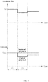
- FIG. 7 is a time-sequence diagram of an operation of the projection system 100.
- the signal source 120 provides the image data to be displayed to the signal processor 130.
- the signal processor 130 analyzes the image data. It is assumed that the image data includes first subframe image data and second subframe image data.
- the highest grayscale value of a plurality of pixels of the first subframe image data reaches the grayscale maximum value G Max (e.g., 255 grayscale), that is, being greater than or equal to the preset value (e.g., 230 grayscale).
- G Max e.g., 255 grayscale
- the highest grayscale value (e.g., 228 grayscale) of a plurality of pixels of the second subframe image data does not reach the grayscale maximum value G Max (e.g., 255 grayscale) and is also smaller than the preset value (e.g., 230 grayscale), that is, being greater than or equal to the preset value (e.g., 230 grayscale).
- G Max e.g., 255 grayscale
- preset value e.g., 230 grayscale
- the signal processor 130 determines, according to the highest grayscale value (e.g., 255 grayscale) of the plurality of pixels of the first subframe image data, that the first subframe image data does not need to have the grayscale increased, and the signal processor 130 provides the first subframe image data (i.e., the original first subframe image data) to the DMD in a first time period. Moreover, the driving member 140 also judges or receives, according to the image data, the signal output by the signal processor 130, so as to get that the adjustment of the luminous flux is not required.
- the highest grayscale value e.g., 255 grayscale
- the driving member 140 controls the adjusting member 150 in such a manner that the luminous flux of the illumination light is maintained at the standard luminous flux L O and provides the illumination light of the standard luminous flux L O to the DMD.
- the DMD modulates the illumination light of the standard luminous flux L O according to the original first sub frame image data, to obtain the projection light.
- the signal processor 130 determines, according to the highest grayscale values of the plurality of pixels of the second subframe image data (e.g., 228 grayscale, which is lower than the preset value of 230 grayscale), that the first subframe image data needs to have the grayscale increased.
- the driving member 140 also determines or receives, according to the image data, the signal output by the signal processor 130, to get that the luminous flux needs to be adjusted.
- the driving member 140 controls the adjusting member 150 in such a way that the luminous flux of the illumination light is adjusted to be 1/k of the standard luminous flux Lo, and provides the illumination light having luminous flux that is only 1/k of the standard luminous flux L O to the DMD.
- the DMD modulates, according to the second subframe image data having the increased grayscale, the illumination light having the luminous flux of L O /k to obtain the projection light.
- the signal processor 130 increases the grayscale values of the plurality of pixels of the image data, and the light emitting device 110 reduces the luminous flux of the illumination light.
- the DMD modulates, according to the image data with the increased grayscale value, the illumination light with the reduced luminous flux to generate the projection light.
- the reduction ratio of the luminous flux of the illumination light is adapted to the increase ratio of the grayscale value of the image data.
- the increase in the grayscale value results in the increase of the "ON" time duration of each mirror of the DMD, while the "OFF" time duration is reduced, the stray light generated by in the "OFF" time duration is reduced and the influence of the stray light on the contrast of the projection system 100 is reduced, thereby improving the contrast of the projection system 100.
- FIG. 8 is a structural schematic diagram of a projection system 200 capable of improving image contrast according to a second embodiment of the present disclosure.
- the projection system 200 of the second embodiment is substantially the same as the projection system 100 of the first embodiment. That is, the description of the projection system 100 of the first embodiment is basically applicable to the projection system 200 of the second embodiment, and a difference between the two mainly lies in that in the second embodiment, the adjusting member 250 is disposed in the optical system 223, and the adjusting member 250 is a liquid crystal lens.
- the driving member 240 controls the divergence angle, the F number, and the luminous flux of the illumination light through the liquid crystal lens.
- the liquid crystal lens may be the last lens of the optical system
- the driving member 240 can control arrangement of liquid crystals in the liquid crystal lens by change in a driving voltage, such that a refractive index of the liquid crystal lens is changed, and a focal length of the liquid crystal lens is also changed, thereby changing the divergence angle, the F number, and the luminous flux of the illumination light.
- an area of a cross section of a light beam of the illumination light incident to a position of an incident surface of the light homogenizing device 214 is larger than an area of the incident surface of the light homogenizing device 214. That is, the adjusting member 250 adjusts the area of the cross section of the light beam of the illumination light incident to the position of the incident surface of the light homogenizing device 214, in such a manner that the area of the cross section of the light beam of the illumination light is greater than the area of the incident surface of the light homogenizing device 214, so as to achieve that the luminous flux of the illumination light is adjusted to be smaller than the standard luminous flux.
- the magnitude of the reduction of the divergence angle and the magnitude of the increase of the F number depend on the magnitude of the required reduction of the luminous flux. In other words, it is needed to calculate, according to the magnitude of the reduction of the luminous flux, how many degrees the divergence angle needs to be reduced, so that the area of the cross section of the light beam exceeds the area of the incidence surface of the light homogenizing device 214.
- both the focal lengths of the liquid crystal lens before and after the adjustment are larger than the distance between the liquid crystal lens and the incident surface of the light homogenizing member 114. Because, if smaller, turning down the divergence angle of the illumination light cannot increase the cross section of the light beam incident on the incident surface of the light homogenizing member 114. As shown in FIG. 9 , if the focal length of the liquid crystal lens is smaller than the distance between the liquid crystal lens and the light homogenizing member 114, then after the divergence angle of the illumination light is reduced, the cross section of its light spot incident on the incident surface of the light homogenizing device 114 becomes smaller instead.
- FIG. 9 is a flow chart diagram of a projection method of the present disclosure.
- the projection method of the present disclosure can be applied to the projection systems 100 and 200 of the first and second embodiments described above.
- the projection method can include following steps S1, S2, S3, S4, and S5.
- Step S1 image data is received.
- the image data includes a plurality of grayscale values, and each grayscale value corresponds to one pixel.
- the step S1 can be performed by the signal processor 130. That is, the signal processor 130 can receive the image data sent by the signal source 120.
- Step S2 the grayscale values of the plurality of pixels of the image data are increased.
- the grayscale values of respective pixels of the image data can be analyzed.
- the grayscale values of the respective pixels of the image data are increased.
- the step S2 can be performed by the signal processor 130. That is, the signal processor 130 receives the image data sent by the signal source 120 and analyzes the highest grayscale value of the respective pixels of the image data.
- the signal processor 130 increases the grayscale values of the respective pixels of the image data.
- the image data can be subframe image data.
- the subframe image data may be red subframe image data, green subframe image data or blue subframe image data.
- the signal processor 130 can increase the grayscale values of the respective pixels of the subframe image data and provide the subframe image data with the increased grayscale values to the DMD.
- the projection system 100, 200 using the projection method can display a grayscale range of 0 to G Max , such as 0 to (2 m -1) grayscale, where m can be 8, the grayscale range may be 0 to 255 grayscale, and G Max represents a grayscale maximum value that the projection system 100, 200 can display.
- the signal processor 130 can analyze the highest grayscale value G L in the respective pixels of the image data. It can be understood that the highest grayscale value is generally smaller than or equal to the grayscale maximum value G Max , and the highest grayscale value G L is compared with the preset value G R .
- the preset value G R may also be smaller than or equal to the grayscale maximum value G Max .
- the preset value is 90% of the grayscale maximum value G Max , that is, when the grayscale maximum value is 255 grayscale, the preset value may be 230 grayscale.
- the step S2 can further include following steps of: calculating an adjustment coefficient, increasing the grayscale values of the respective pixels of the image data according to the adjustment coefficient, and providing the image data with the increased grayscale values to the DMD.
- the adjustment coefficient k can be equal to the maximum grayscale value G Max /the highest grayscale value G L . Since the highest grayscale value G L of the image data is generally smaller than the maximum grayscale value G Max , k is greater than or equal to 1.
- the signal processor 130 performs control in such a manner that a grayscale value of each pixel of the image data is adjusted to be k times. It is assumed that an original grayscale value of any one pixel of the image data is G i , then the adjusted grayscale value of the pixel is kG i .
- the data one the one frame of the image includes red subframe image data, green subframe image data, and blue subframe image data. Assuming that in the data on the one frame of image, an original red grayscale value, an original green grayscale value and an original blue grayscale value of one pixel are respectively (50, 60, 80), and an adjustment coefficient can be set to 2 times.
- the signal processor 130 adjusts, according to the adjustment coefficient, the red grayscale value, the green grayscale value, and the blue grayscale value of the pixel to twice the original ones, i.e., (100, 120, 160), and the luminous flux of the illumination light can be adjusted to half of the original illumination light, i.e., 50%, and the grayscale of the image data is also accurately restored.
- Step S3 the illumination light is provided, and the luminous flux of the illumination light is reduced.
- a ratio by which the luminous flux of the illumination light is reduced is adapted to a ratio by which the grayscale value of the image data is increased.
- the step S3 can be performed by the light emitting device.
- Step S4 the illumination light with the reduced luminous flux is modulated based on the image data with the increased grayscale value, to generate projection light required for the projection image.
- the step S3 can be performed by the DMD.
- the step S3 can include following steps of: adjusting the luminous flux of the illumination light to be smaller than the standard luminous flux when the highest grayscale value in the respective pixels of the image data is lower than the preset value, in such a manner that the luminous flux of the adjusted illumination light is adapted to the image data with the increased grayscale value.
- the light emitting device 110 can include a driving member 140 and an adjusting member 150, and the driving member 140 controls the adjusting member 150 to perform luminous flux adjustment on the illumination light emitted by the light emitting device 110.
- the driving member 140 of the light emitting device 110 can directly analyze the image data to determine, according to the image data, whether the signal processor 130 will increase the grayscale values of the respective pixels of the image data. If the driving member 140 of the light emitting device 110 determines, according to the image data, that the signal processor 130 will increase the grayscale values of the respective pixels of the image data, then the driving member 140 of the light emitting device 110 controls the adjusting member 150 to correspondingly reduce the luminous flux of the illumination light. Specifically, the driving member 140 of the light emitting device 110 can analyze whether the highest grayscale value in the respective pixels of the image data is lower than the preset value. When the highest grayscale value in the respective pixels of the image data is lower than the preset value, the driving member 140 of the light emitting device 110 controls the adjusting member 150 to correspondingly reduce the luminous flux of the illumination light.
- the driving member 140 of the light emitting device 110 can receive a luminous flux adjustment control signal sent when the signal processor 130 turns up the grayscale values of the respective pixels of the image data is raised, and then the driving member 140 of the light emitting device 110 can control, according to the luminous flux adjustment signal sent by the signal processor 130, the adjusting member 150 to reduce the luminous flux of the illumination light.
- the signal processor 130 can analyze whether the highest grayscale value in the respective pixels of the image data is lower than the preset value.
- the signal processor 130 increases the grayscale values of the plurality of pixels of the image data, provides the image data with the increased grayscale values to the DMD and transmits the luminous flux adjustment signal to the driving member of the light emitting device, such that the driving member 140 of the light emitting device 110 correspondingly controls the adjusting member to reduce the luminous flux of the illumination light according to the luminous flux adjustment signal.
- the driving member 140 of the light emitting device 110 can control, according to the adjustment coefficient k, the adjusting member 150 to adjust the luminous flux of the illumination light to be adapted to the increased grayscale values of the respective pixels of the image data.
- the signal processor 130 can send, according to the adjustment coefficient k, the luminous flux adjustment signal representing the adjustment coefficient k to the driving member 140 of the light emitting device 110.
- the driving member 140 of the light emitting device 110 can control, according to the adjustment coefficient k, the adjusting member 150 to adjust the luminous flux of the illumination light to be adapted to the increased grayscale value of the respective pixel of the image data.
- the adjusting member 150 can be an adjustable aperture disposed in the relay system 115 of the light emitting device 110, and it is used to change the divergence angle of the illumination light (or the F number of the illumination light), and the adjustable aperture can be disposed at an aperture stop of the relay system 115.
- the adjustable aperture is used for blocking a peripheral portion of the light beam of the illumination light incident to the adjustable aperture, so as to reduce the divergence angle, increase the F number and reduce the luminous flux of the illumination light emitted from the adjustable aperture with respect to the incident illumination light.
- the driving member 140 can include a driving motor, and the driving motor can drive the adjustable aperture to control the divergence angle of the illumination light.
- a magnitude of the reduction of the divergence angle and a magnitude of the increase of the F number depend on a magnitude of the luminous flux required to be reduced, and in the present embodiment, they depend on an amount of the illumination light that is incident to the adjustable aperture while being blocked by the adjustable aperture, i.e., an aperture size of the adjustable aperture.
- the relay system 115 includes a relay lens 116. It can be seen from a main optical axis of an edge ray of the light homogenizing device 114 (e.g., the square bar) that a position where the main optical axis of the edge ray emitted by the light homogenizing device 114 and a central axis of the relay system 115 intersect is the position of the aperture stop. Specifically, the center of the adjustable aperture and the central axis of the relay system 115 coincide and are arranged perpendicularly. The position of the main optical axis of the edge ray emitted by the light homogenizing device 114 may be defined by the relay lens 116.
- an upper edge ray of the light homogenizing device 114 is exactly incident to a position of a lower edge of the DMD after passing through the relay lens 116, while a lower edge ray of the light homogenizing device 114 is exactly incident to the position of the upper edge of the DMD after passing through the relay lens 116, such that the light spot emitted by the light homogenizing device is exactly imaged, via the relay lens 116, to surfaces of the DMD having the respective mirrors.
- the adjustable aperture may have an actual thickness, which, however, has little impact on the adjustment of the F number and can be ignored, so the potential influence of the actual thickness of the adjustable aperture is not considered here, as long as there is coincidence between the position of the adjustable aperture and the position of the aperture stop.
- the adjusting member 150 can be disposed in an optical system 113, and the adjusting member 150 is a liquid crystal lens.
- the driving member 140 controls the divergence angle, the F number, and the luminous flux of the illumination light through the liquid crystal lens.
- the liquid crystal lens can be the last lens of the optical system, and the driving member 140 can control arrangement of liquid crystals in the liquid crystal lens by change in a driving voltage, such that a refractive index of the liquid crystal lens is changed, and a focal length of the liquid crystal lens is also changed, thereby changing the divergence angle, the F number, and the luminous flux of the illumination light.
- an area of a cross section of a light beam of the illumination light incident to a position of an incident surface of the light homogenizing device 214 is larger than an area of the incident surface of the light homogenizing device 214. That is, the adjusting member 250 adjusts the area of the cross section of the light beam of the illumination light incident to the position of the incident surface of the light homogenizing device 214, in such a manner that the area of the cross section of the light beam of the illumination light is greater than the area of the incident surface of the light homogenizing device 214, so as to achieve that the luminous flux of the illumination light is adjusted to be smaller than the standard luminous flux.
- the magnitude of the reduction of the divergence angle and the magnitude of the increase of the F number depend on the magnitude of the required reduction of the luminous flux. In other words, it is needed to calculate, according to the magnitude of the reduction of the luminous flux, how many degrees the divergence angle needs to be reduced, so that the area of the cross section of the light beam exceeds the area of the incidence surface of the light homogenizing device 214.
- both the focal lengths of the liquid crystal lens before and after the adjustment are larger than the distance between the liquid crystal lens and the incident surface of the light homogenizing member 114. Because, if smaller, turning down the divergence angle of the illumination light cannot increase the cross section of the light beam incident on the incident surface of the light homogenizing member 114. As shown in FIG. 10 , if the focal length of the liquid crystal lens is smaller than the distance between the liquid crystal lens and the light homogenizing member 114, then after the divergence angle of the illumination light is reduced, the cross section of its light spot incident on the incident surface of the light homogenizing device 114 becomes smaller instead.
- the projection light obtained by the DMD modulating the illumination light of the standard luminous flux L O according to the original grayscale value of the image data can exactly restore the grayscale of the image data.
- the light emitting device adjusting the luminous flux of the illumination light according to the adjustment coefficient k is to adjust the luminous flux of the illumination light to be 1/k of the original luminous flux.
- the adjusted luminous flux emitted by the light emitting device 110 is 1/k of the standard luminous flux, i.e., L O /k.
- Each of the mirror units of the DMD receives the illumination light having the luminous flux of L O /k and modulates the illumination light having the luminous flux of L O /k according to the adjusted grayscale value kG i , to generate projection light.
- the luminous flux of the projection light is kG i ⁇ L O /k, which is the same as the luminous flux G i ⁇ L O that is obtained by modulating the original luminous flux L O according to the original grayscale value G i .
- the projection light emitted by each of the mirror units 102 of the DMD accurately restores the grayscale value of the respective pixel of the image data.
- a projection image is generated according to the projection light.
- the brightness of the projection light matches the image data prior to increasing the grayscale values.
- the step S5 can be implemented by a projection lens.
- the projection lens can receive the projection light emitted by the DMD and project the projection light on a projection screen to display the projection image. Since the reduction ratio of the luminous flux of the illumination light is adapted to the increase ratio of the grayscale value of the image data, the brightness of the projection light matches the image data prior to increasing the grayscale values.
Landscapes
- Engineering & Computer Science (AREA)
- Multimedia (AREA)
- Signal Processing (AREA)
- Physics & Mathematics (AREA)
- General Physics & Mathematics (AREA)
- Projection Apparatus (AREA)
- Control Of Indicators Other Than Cathode Ray Tubes (AREA)
- Optical Elements Other Than Lenses (AREA)
- Mechanical Light Control Or Optical Switches (AREA)
- Transforming Electric Information Into Light Information (AREA)
Abstract
Description
- The present disclosure relates to a projection system and a projection method.
- An existing projection system generally includes a light source device, a spatial light modulator (such as a LCOS spatial light modulator or a DMD spatial light modulator), and a projection lens. The light source device emits, for example, light of three colors of red, green and blue. The spatial light modulator image-modulates the light emitted by the light source device based on image data, and the projection lens projects image light output by the spatial light modulator to display a projection image. However, the existing projection system may have low contrast, which needs to be improved.
- In order to solve the problem of relatively low contrast of the projection system in the related art, the present disclosure provides a projection system and a projection method having relatively high contrast.
- A projection system includes:
- a signal processor configured to receive image data including a plurality of grayscale values, each of which corresponds to one pixel, wherein the signal processor is further configured to increase grayscale values of a plurality of pixels of the image data;
- a light source configured to emit illumination light,
- an optical relay system configured to provide the illumination light to a DMD for modulating to obtain projection light required for a projection image;
- an adjusting member configured to reduce luminous flux of the illumination light provided to the DMD when the grayscale values of the plurality of pixels of the image data are increased so that a reduction ratio of the luminous flux of the illumination light matches an increase ratio of the plurality of grayscale values of the image data; and
- the DMD configured to modulate the adjusted illumination light according to the image data with the increased grayscale values, to generate the projection light required for the projection image,
- brightness of the projection light matches the image data prior to increasing the grayscale values.
- In an embodiment, the signal processor receives the image data, the image data includes subframe image data, the signal processor determines whether a highest grayscale value of respective pixels in the subframe image data is smaller than a preset value, when the highest grayscale value of the respective pixels in the subframe image data is smaller than the preset value, the signal processor controls to increase the grayscale values of the respective pixels of the subframe image data, wherein a light emitting device adjusts the luminous flux of the illumination light to be smaller than standard luminous flux LO when the highest grayscale value of the respective pixels in the subframe image data is smaller than the preset value; and when the highest grayscale value of the respective pixels in the subframe image data is larger than or equal to the preset value, the signal processor keeps the grayscale values of the respective pixels of the subframe image data unchanged and provides the subframe image data to the DMD; the light emitting device emits illumination light of the standard luminous flux Lo, and the DMD modulates the illumination light of the standard luminous flux LO based on the subframe image data with the unchanged grayscale values, to generate the projection light required for the projection image.
- In an embodiment, a grayscale maximum value that the projection system can reach is set to be GMax, the preset value is set to be GR, and the preset value GR is smaller than or equal to the grayscale maximum value GMax.
- In an embodiment, the preset value is set to be 90% of the grayscale maximum value GMax.
- In an embodiment, the signal processor further calculates an adjustment coefficient k when the highest grayscale value of the respective pixels in the subframe image data is smaller than the preset value, the adjustment coefficient k is equal to GMax/GL, GL represents the highest grayscale value of the respective pixels in the subframe image data, the signal processor adjusts a grayscale value of each of the plurality of pixels of the image data to be k times the grayscale value of each of the pixels of the image data based on the adjustment coefficient k, and the luminous flux of the illumination light emitted by the light emitting device is adjusted to be 1/k of the standard luminous flux Lo.
- In an embodiment, the adjusting member is configured to adjust the luminous flux of the illumination light emitted by the light source.
- In an embodiment, the adjusting member is configured to reduce a divergence angle of the illumination light provided by the optical relay system, increase an F number of the illumination light provided by the optical relay system, and reduce the luminous flux of the illumination light provided by the optical relay system.
- In an embodiment, the adjusting member includes an adjustable aperture, the adjustable aperture is disposed at an aperture stop of the optical relay system; the adjustable aperture is configured to block a peripheral portion of a light beam of the illumination light incident to the adjustable aperture, such that the illumination light exiting from the adjustable aperture has a smaller divergence angle, an increased F number, and a reduced luminous flux with respect to the illumination light incident to the adjustable aperture.
- In an embodiment, the optical relay system includes a light homogenizing member configured to homogenize the illumination light; the adjusting member includes a liquid crystal lens located on an optical path prior to the light homogenizing member, wherein light exiting from the liquid crystal lens irradiates on an incident surface of the light homogenizing member; and the liquid crystal lens is configured to reduce the divergence angle of the illumination light, so that a cross sectional area of the illumination light, when being incident to a position of the incident surface of the light homogenizing member, is larger than an area of the incident surface, such that the illumination light entering the light homogenizing member has a reduced divergence angle, an increased F number, and reduced luminous flux.
- A projection method, including steps of:
- receiving image data including a plurality of grayscale values, each of which corresponds to one pixel;
- increasing grayscale values of a plurality of pixels of the image data;
- providing illumination light, and reducing luminous flux of the illumination light, wherein a reduction ratio of the luminous flux of the illumination light matches an increase ratio of the plurality of grayscale values of the image data;
- modulating the illumination light with the reduced luminous flux based on the image data with the increased grayscale values, to generate projection light required for a projection image; and
- generating a projection image based on the projection light, wherein brightness of the projection light matches the image data prior to increasing the grayscale values.
- In an embodiment, in the projection method, when a highest grayscale value of the plurality of pixels in the image data is smaller than a preset value, the grayscale values of the plurality of pixels of the image data is increased; when a highest grayscale value of respective pixels in a subframe image data is larger than or equal to the preset value, grayscale values of the respective pixels of the subframe image data are kept unchanged, the luminous flux of the illumination light is controlled to be standard luminous flux Lo, and the illumination light of the standard luminous flux LO is modulated based on the image data with the unchanged grayscale values to generate the projection light required for the projection image.
- In an embodiment, in the projection method, a grayscale maximum value that the projection system using the method can reach is set to be GMax, the preset value is set to be GR, and the preset value GR is smaller than or equal to the grayscale maximum value GMax.
- In an embodiment, in the projection method, the preset value is set to be 90% of the grayscale maximum value GMax.
- In an embodiment, in the projection method, an adjustment coefficient k is calculated when the highest grayscale value of the respective pixels in the subframe image data is smaller than the preset value, wherein the adjustment coefficient k is equal to GMax/GL, and GL represents the highest grayscale value of the respective pixels in the subframe image data.
- In an embodiment, in the projection method, a grayscale value of each of pixels of the image data is adjusted to be k times the grayscale value of each of the plurality of pixels of the image data based on the adjustment coefficient k, that is, a grayscale value of any one of the plurality of pixels of the image data is set to be Gi, and then an increased grayscale value corresponding to the grayscale value Gi of the pixel of the image data is k×Gi, and the luminous flux of the illumination light is adjusted to be 1/k of the standard luminous flux Lo and thus the luminous flux of the illumination light is LO/k.
- Compared with the related art, in the projection system and the projection method, the grayscale values of the pixels of the image data are increased, and the luminous flux of the illumination light is reduced. Then the illumination light with the reduced luminous flux is modulated according to the image data with the increased grayscale values to generate the projection light, and a proportion of the reduction of the luminous flux of the illumination light is adapted to a proportion of the increase of the grayscale value of the image data, so that the original grayscale values of the plurality of pixels of the image data can be accurately restored. In addition, since the increase in the grayscale value results in the increase of the "ON" time duration of each mirror of the DMD, while the "OFF" time duration is reduced, the stray light generated in the "OFF" time duration is reduced and the influence of the stray light on the contrast of the projection system is reduced, thereby improving the contrast of the projection system and the projection method.
-
-
FIG. 1 is a schematic diagram of a test screen for ANSI contrast. -
FIG. 2 is a structural schematic diagram of a DMD. -
FIG. 3 is a schematic diagram showing an optical path of stray light generated when a mirror unit of a DMD is in an "OFF" state. -
FIG. 4 illustrates a comparison of stray light generated by illumination light, which has different divergence angles, irradiating on the same DMD. -
FIG. 5 is a schematic diagram of a definition of a divergence angle of light. -
FIG. 6 is a structural schematic diagram of a projection system according to a first embodiment of the present disclosure. -
FIG. 7 is a schematic diagram of a projection time-sequence of a projection system ofFIG. 6 . -
FIG. 8 is a structural schematic diagram of a projection system according to a second embodiment of the present disclosure. -
FIG. 9 is a schematic diagram showing adjustment of illumination light by an adjusting member shown inFIG. 8 . -
FIG. 10 is a flow chart of a projection method of the present disclosure. -
-
Projection system -
Mirror unit 102 -
Substrate 101 -
Light emitting device 110 -
Light source 111 -
Optical relay system 112 -
Optical system - Light
homogenizing device 114 -
Relay system 115 -
Relay lens 116 -
Signal source 120 -
Signal processor 130 -
Driving member - Adjusting
member - Step S1-S5
- The present disclosure will be further illustrated by the following detailed description with reference to the accompanying drawings.
- First of all, it should be noted that contrast of a projection system generally refers to a ratio of a full white field center illuminance value to a full black field center illuminance value in a fixed projection image. Normally, in the case of the full black field, a power source can be turned off directly to falsely increase the contrast. Therefore, there is also a definition of ANSI contrast, which is tested as follows. In an image, full black regions and full white regions are alternate to present a form of 4×4 (as shown in
FIG. 1 ), and the test is performed under this image to obtain ANSI contrast CR. Specifically, the ANSI contrast CR conforms to a following formula:
- Wherein Ebright represents the center illuminance of the white region, Eblack represents the center illuminance of the black region, Ela represents center illuminance of ambient light when image projection is not performed in the white region, Eba represents the center illuminance of the ambient light when image projection is not performed in the black region, i represents a serial number of the black region and the white region (the above test image includes a total of 8 black regions and 8 white regions, so i = 1 to 8).
- Generally, a brightness perception range that is common and suitable in daily life is in a range of about 0.01 nits -1000 nits, and the contrast is about 100000:1, while a range that can be modulated by a normal spatial light modulator is much lower than a perception range of a human eye. It is desirable that the projection display images are as close as possible to the perception of the human eye on natural environment, and HDR technology has been proposed to improve dynamic ranges of projection display systems.
- There are generally three ways to improve the contrast: (1) ensuring brightness of a pixel having the highest brightness in one frame of image, and reducing overall brightness of other pixels; (2) ensuring brightness of a pixel having the lowest brightness in one frame of image, and improving overall brightness of other pixels; and (3) ensuring brightness of a certain pixel that has brightness between the highest brightness and the lowest brightness in one frame of image, increasing overall brightness of a pixel having relatively high brightness and reducing overall brightness of a pixel having relatively low brightness. Since the highest brightness of a frame of image is limited by the light source brightness and the optical system transmission efficiency, the method of reducing the brightness of dark pixels to improve the contrast is faster and more flexible.
- A DMD (Digital Micro-mirror Device) is a commonly used spatial light modulator, and it is an image chip developed by the American TI (Texas Instruments) Company and widely used in the projection display industry. As shown in
FIG. 2, FIG. 2 is a structural schematic diagram of a DMD. The DMD includes asubstrate 101, and a plurality ofmirror units 102 disposed on thesubstrate 101 and arranged in a matrix. A driving circuit may be disposed inside the substrate 101 (such as a silicon substrate), for controlling themirror unit 102 to rotate rapidly. Each of themirror units 102 is a light switch whose switching time is in an order of microseconds. Each of themirror units 102 may include an "ON" state (i.e., an open state) and an "OFF" state (i.e., a closed state). The human eye actually integrates brightness generated under the "ON" state, and the longer the time duration of the "ON" state is (or the shorter the time duration of the "OFF" state) is, the higher the brightness is. The time duration of the "ON" state or the "OFF" state of each of themirror units 102 is controlled by a grayscale value of its corresponding pixel, and the higher the grayscale is, the longer the time duration of the "ON" state is, and the shorter the time duration of the "OFF" state is. For example, a pixel has a red grayscale value of 127, and a time occupying ratio of the "OFF" state of thecorresponding mirror unit 102 is 1/2. When the grayscale value is increased to 191, the time occupying ratio of the "OFF" state of thecorresponding mirror unit 102 is 1/4. - Specifically, when the DMD is in operation, the illumination light is incident on a surface of the DMD at a certain angle. When the
mirror unit 102 of the DMD is in the "ON" state, the light reflected by themirror unit 102 of the DMD enters a lens and is finally projected onto the screen; and when themirror unit 102 of the DMD is in the "OFF" state, themirror unit 102 of the DMD is turned over and the reflected light ray is prevented from entering the lens. - However, it has been found by research that when the
mirror unit 102 of the DMD is in the "OFF" state, since a gap between themirror units 102 becomes large, the illumination light is incident on thebottom substrate 101 and repeatedly reflected therein to generate stray light, which enters the lens, thereby ultimately resulting in reduced contrast of the projection system adopting the DMD. Specifically, referring toFIG. 3, FIG. 3 is a schematic diagram of an optical path of the stray light generated when themirror unit 102 of the DMD is in the "OFF" state. As shown inFIG. 3 , the illumination light is incident on thesubstrate 101 from the gap between twoadjacent mirror units 102, and it is repeatedly reflected between thesubstrate 101 and a back portion of themirror unit 102 to generate the stray light. The stray light may leak from an edge of themirror unit 102, thereby resulting in the reduced contrast of the projection system employing the DMD. - Furthermore, referring to
FIG. 4, FIG. 4 illustrates a comparison of stray light generated by the illumination light, which has different divergence angles, irradiating on the same DMD. A left side illustrates a schematic diagram of the stray light generated by illumination light, which has a relatively large divergence angle (a relatively small F number), irradiating on the DMD, and a right side illustrates a schematic diagram of the stray light generated by illumination light, which has a relatively small divergence angle (a relatively large F number), irradiating on the DMD. It would be appreciated that the divergence angle of light is used to measure a speed at which the light beam diverges outwardly from a beam waist. Specifically, the beam divergence angle is a derivative of a beam radius to a far field axial position, that is, a distance from the beam waist is much larger than the Rayleigh length. Referring toFIG. 5, FIG. 5 is a schematic diagram of a definition of the divergence angle, where the divergence angle θ = tan (x / 2L), the F number, i.e., F # = 1/2 Sin θ, wherein x represents a diameter of a light spot, and L represents a distance from a test source to the light spot. - As shown in
FIG. 4 , when themirror unit 102 of the DMD is in the "OFF" state, the gap between the mirror units becomes large, and the illumination light is incident on thebottom substrate 101 thereof and repeatedly reflected therein to form the stray light. The region at which the stray light between theadjacent mirror units 102 is irradiated is a stray light region, and the larger the divergence angle of the illumination light (the smaller the F number) is, there is more stray light, and the larger the influence on the contrast of the projection system is, that is, the more the contrast of the corresponding projection system is lowered. As shown inFIG. 4 , in the "OFF" state, the stray light generated by the illumination light having the relatively large divergence angle at the left side is obviously more than the stray light generated by the illumination light having the relatively small divergence angle at the right side. Therefore, the contrast of the projection system corresponding to the illumination light having the relatively large divergence angle at the left side is smaller than the contrast of the projection system corresponding to the illumination light having the relatively small divergence angle at the right side. - Therefore, in order to improve the contrast, when the
mirror unit 102 of the DMD is in the "OFF" state, the divergence angle of the illumination light should be controlled to be as small as possible, that is, the luminous flux of the illumination light is controlled to be low and no light enters the lens to be projected onto the screen. That is, eliminating the stray light of themirror unit 102 of the DMD in the "OFF" state or reducing the time occupying ratio of the "OFF" state thereof (that is, increasing the image signal value or the grayscale value) will help to improve the contrast of the projection system. - Based on the above analysis, the present disclosure provides a
projection system 100 having high dynamic contrast. Referring toFIG. 6, FIG. 6 is a structural schematic diagram of aprojection system 100 capable of improving the image contrast according to a first embodiment of the present disclosure. Theprojection system 100 includes alight emitting device 110, a DMD, asignal source 120, and asignal processor 130. Thelight emitting device 110 is configured to emit illumination light and provide the illumination light to the DMD. Thesignal source 120 is configured to provide image data to be displayed to thesignal processor 130. The image data includes a plurality of grayscale values, and each grayscale value corresponds to one pixel. Thesignal processor 130 is configured to increase the grayscale values of a plurality of pixels of the image data and provide image data with the increased grayscale values to the DMD. Standard luminous flux of the illumination light emitted by thelight emitting device 110 is Lo. Thelight emitting device 110 is further configured to reduce the luminous flux of the illumination light when the grayscale values of the plurality of pixels of the image data are increased, such as being adjusted to be smaller than the standard luminous flux Lo. A reduction ratio of the luminous flux of the illumination light matches an increase ratio of the grayscale value of the image data. Thelight emitting device 110 provides the adjusted illumination light to the DMD. The DMD modulates the adjusted illumination light according to the image data with the increased grayscale values, to generate projection light required by the projection image, and the brightness of the projection light matches the image data prior to increasing the grayscale value. - Compared with the related art, in the
projection system 100, thesignal processor 130 increases the grayscale values of a plurality of pixels of the image data. Thelight emitting device 110 can reduce the luminous flux of the illumination light. The DMD modulates, according to the image data with the increased grayscale value, the illumination light with reduced luminous flux, to generate projection light. Thus, original grayscale values of a plurality of pixels of the image data can be accurately restored. In addition, since the increase in the grayscale value results in the increase of the "ON" time duration of each mirror of the DMD as well as the reduction of the "OFF" time duration, the stray light generated by in the "OFF" time duration is reduced and the influence of the stray light on the contrast of the projection system is reduced, thereby improving the contrast of theprojection system 100. - It can be understood that the
light emitting device 110 correspondingly turning down the luminous flux is to adjust, based on the standard luminous flux LO emitted when thelight emitting device 110 does not adjust the luminous flux, the luminous flux of the illumination light to be smaller than the standard luminous flux LO of the illumination light. When the grayscale value of the respective pixel of the image data has substantially reached a grayscale maximum value and it is difficult to further increase, thesignal processor 130 does not need to increase the image data but keeps the grayscale value of the respective pixel of the image data unchanged and provides the image data with the unchanged grayscale value (i.e., the original image data) directly to the DMD. Moreover, thelight emitting device 110 directly emits the illumination light of the standard luminous flux LO to the DMD. The DMD modulates the illumination light of the standard luminous flux LO according to the original image data to generate the projection light. - Specifically, the image data may be subframe image data. The subframe image data may be red subframe image data, green subframe image data or blue subframe image data. When the highest grayscale value in the respective pixel in the subframe image data is lower than a preset value, the
signal processor 130 may increase the grayscale values of the plurality of pixels of the subframe image data and provide the subframe image data with the increased grayscale values to the DMD. - The
light emitting device 110 also turns down the luminous flux of the illumination light when the highest grayscale value in the respective pixel of the subframe image data is lower than the preset value, so as to make the luminous flux of the adjusted illumination light be adapted to the image data with the increased grayscale values. Specifically, thelight emitting device 110 may include a drivingmember 140 and an adjustingmember 150. The drivingmember 140 controls the adjustingmember 150 to perform luminous flux adjustment on the illumination light emitted by the light emitting device. - In an embodiment, the driving
member 140 of thelight emitting device 110 may directly analyze the image data to determine, according to the image data, whether thesignal processor 130 will increase the grayscale value of the respective pixel of the image data. If the drivingmember 140 of thelight emitting device 110 determines, according to the image data, that thesignal processor 130 will increase the grayscale value of the respective pixel of the image data, and then the drivingmember 140 of thelight emitting device 110 controls the adjustingmember 150 to correspondingly reduce the luminous flux of the illumination light. Specifically, the drivingmember 140 of thelight emitting device 110 may analyze whether the highest grayscale value in the respective pixel of the image data is lower than a preset value, and when the highest grayscale value in the respective pixel of the image data is lower than the preset value, the drivingmember 140 of thelight emitting device 110 controls the adjustingmember 150 to correspondingly reduce the luminous flux of the illumination light. - In another embodiment, the driving
member 140 of thelight emitting device 110 can receive a luminous flux adjustment control signal sent when thesignal processor 130 turns up grayscale values of respective pixels of the image data, and then the drivingmember 140 of thelight emitting device 110 can control, according to the luminous flux adjustment signal sent by thesignal processor 130, the adjustingmember 150 to reduce the luminous flux of the illumination light. Specifically, thesignal processor 130 may analyze whether the highest grayscale value in the respective pixel of the image data is smaller than the preset value. When the highest grayscale value in the respective pixel of the image data is smaller than the preset value, thesignal processor 130 increases the grayscale values of the plurality of pixels of the image data, provides the image data with the increased grayscale values to the DMD and also transmits the luminous flux adjustment signal to the drivingmember 140 of thelight emitting device 110, such that the drivingmember 140 of thelight emitting device 110 correspondingly control the adjustingmember 150 to reduce the luminous flux of the illumination light according to the luminous flux adjustment signal. When the highest grayscale value of the respective pixel in the subframe image data is larger than or equal to the preset value, thesignal processor 130 keeps the grayscale value of the respective pixel of the subframe image data unchanged and provides the subframe image data to the DMD. Thelight emitting device 110 emits the illumination light of the standard luminous flux Lo, and the DMD modulates, according to the subframe image data with the unchanged grayscale value, the illumination light of the standard luminous flux Lo, to generate projection light required for the projection image. - Specifically, it is assumed that the
projection system 100 can display a grayscale ranging from 0 to GMax, such as 0 to (2m-1) grayscale, where m may be 8, the grayscale range may be 0 to 255 grayscale, and GMax represents a grayscale maximum value that theprojection system 100 can display. Thesignal processor 130 may analyze the highest grayscale value GL in the respective pixel of the image data, and it can be understood that the highest grayscale value is generally smaller than or equal to the grayscale maximum value GMax, and the highest grayscale value GL is compared with the preset value GR. The preset value GR may also be smaller than or equal to the grayscale maximum value GMax. For example, the preset value is 90% of the grayscale maximum value GMax, that is, when the grayscale maximum value is 255 grayscale, the preset value may be 230 grayscale. When the highest grayscale value GL is smaller than the preset value GR, thesignal processor 130 calculates an adjustment coefficient k, increases the grayscale value of the respective pixel of the image data according to the adjustment coefficient k, and provides the image data with the increased grayscale values to the DMD. Specifically, the adjustment coefficient k may be equal to the maximum grayscale value GMax/ the highest grayscale value GL. Since the highest grayscale value GL of the image data is generally smaller than the maximum grayscale value GMax, k is larger than or equal to 1, and the signal processor adjusts the grayscale value of the respective pixel of the image data to be k times. It is assumed that the original grayscale value of any one of the pixels in the image data is G;, then the adjusted grayscale value of the pixel is kG;. - Specifically, the driving
member 140 of thelight emitting device 110 may control, according to the adjustment coefficient k, the adjustingmember 150 to adjust the luminous flux of the illumination light to be adapted to the increased grayscale value of the respective pixel of the image data. Thesignal processor 130 may send, according to the adjustment coefficient k, the luminous flux adjustment signal representing the adjustment coefficient k to the driving member of the light emitting device. The drivingmember 140 of thelight emitting device 110 may control, according to the adjustment coefficient k, the adjustingmember 150 to adjust the luminous flux of the illumination light to be adapted to the increased grayscale value of the respective pixel of the image data. Specifically, the standard luminous flux LO of the illumination light emitted by thelight emitting device 110 can also be regarded as the luminous flux of the illumination light normally emitted by thelight emitting device 110, that is, the luminous flux when k=1. In other words, the projection light obtained by the DMD modulating the illumination light of the standard luminous flux LO according to the original grayscale value of the image data can exactly restore the grayscale of the image data. Thelight emitting device 110 adjusting the luminous flux of the illumination light according to the adjustment coefficient k is to adjust the luminous flux of the illumination light to be 1/k of the original luminous flux. That is, the adjusted luminous flux emitted by thelight emitting device 110 is 1/k of the standard luminous flux, i.e., LO/k. Each of the mirror units of the DMD receives the illumination light having the luminous flux of Lo/k and modulates the illumination light having the luminous flux of LO/k according to the adjusted grayscale value kGi, to generate projection light. The luminous flux of the projection light is kGi ∗LO/k, which is the same as the luminous flux Gi ∗LO that is obtained by modulating the original luminous flux LO according to the original grayscale value Gi. The projection light emitted by each of the mirror units of the DMD accurately restores the grayscale value of the respective pixel of the image data. - Without doubt, in a modified embodiment, the adjustment coefficient k can also be selected according to actual needs. For example, when the grayscale values of the respective pixels of the image data are all smaller than (GMax+1)/2, the adjustment coefficient k may also be set to 2 times, i.e., k=2. Taking data on one frame of image as an example for description, the data includes red subframe image data, green subframe image data, and blue subframe image data. Assuming that in the image on one frame of image, an original red grayscale value, an original green grayscale value and an original blue grayscale value of one pixel are respectively (50, 60, 80), and an adjustment system can be set to 2 times. Therefore, the
signal processor 130 adjusts, according to the adjustment coefficient, the red grayscale value, the green grayscale value, and the blue grayscale value of the pixel to twice the original ones, i.e., (100, 120, 160), and the luminous flux of the illumination light can be adjusted to half of the original illumination light, i.e., 50%, and the grayscale of the image data is also accurately restored. - Further, as shown in
FIG. 6 , thelight emitting device 110 may include alight source module 111 and anoptical relay system 112. Thelight source module 111 emits illumination light. Theoptical relay system 112 is used to perform processing, such as changing an optical path, light homogenizing and the like, on the illumination light and provide the processed illumination light to the DMD. - In an embodiment, the
light emitting device 110 can change the luminous flux of the illumination light, i.e., providing the adjustingmember 150 in thelight source module 111, and the adjustingmember 150 can be a light source driving circuit configured to adjust a driving current of a light emitting element (such as a laser) of thelight source module 111 so as to change the luminous flux of the illumination light. However, in another embodiment, thelight emitting device 110 may also adjust the luminous flux of the illumination light by changing the divergence angle (or the F number of the illumination light) of the illumination light through theoptical relay system 112, i.e., providing the adjustingmember 150 in theoptical relay system 112; or, in still another embodiment, thelight emitting device 110 adjusts the luminous flux of the illumination light by changing the luminous flux of the illumination light emitted by the light source module) and changing the divergence angle of the illumination light (or the F number of the illumination light) in theoptical relay system 112, and provides the adjustingmember 150 respectively in thelight source module 111 and theoptical relay system 112. Specifically, thelight emitting device 110 can reduce the divergence angle of the illumination light provided by theoptical relay system 112, increase the F number of the illumination light provided by theoptical relay system 112, and reduce the luminous flux of the illumination light provided by theoptical relay system 112. - In the present embodiment, the case where the
optical relay system 112 of thelight emitting device 110 adjusts the luminous flux of the illumination light by changing the divergence angle of the illumination light (or the F number of the illumination light) is mainly taken as an example for description. Specifically, it is assumed that when the luminous flux of the illumination light emitted by thelight emitting device 110 is the standard luminous flux Lo, a reference divergence angle of the illumination light emitted by thelight emitting device 110 is θo (its corresponding F number is the reference F number Fo). When the grayscale value of the respective pixel of the image data is increased, thelight emitting device 110 adjusts, according to the adjustment coefficient, the divergence angle of the illumination light to be smaller than the reference divergence angle (or adjust the F number of the illumination light to be larger than the reference F number Fo), and a ratio between the divergence angle of the adjusted illumination light and the reference divergence angle is inversely proportional to the adjustment coefficient (a ratio between the F number of the adjusted illumination light and the reference F number Fo is directly proportional to the adjustment coefficient k), that is, the larger the adjustment coefficient k is, the smaller the ratio between the divergence angle of the adjusted illumination light and the reference divergence angle is (the larger the ratio between the F number of the adjusted illumination light and the reference F number Fo is), that is, the smaller the divergence angle of the adjusted illumination light is (the larger the F number of the adjusted illumination light) is. - In other words, from a viewpoint of the F number adjustment, the
light emitting device 110 can adjust the luminous flux of the illumination light by changing the F number of the illumination light. Specifically, it is assumed that when the luminous flux of the illumination light emitted by the light emitting device is the standard luminous flux Lo, the corresponding F number of the illumination light emitted by thelight emitting device 110 is the reference F number Fo. When the grayscale value of the respective pixel of the image data is increased, thelight emitting device 110 adjusts the F number of the illumination light to be larger than the reference F number Fo according to the adjustment coefficient, and a ratio between the F number of the adjusted illumination light and the reference F number Fo is directly proportional to the adjustment coefficient k, that is, the larger the adjustment coefficient k is, the smaller the ratio between the divergence angle of the adjusted illumination light and the reference divergence angle is, and the larger the ratio of the F number of the adjusted illumination light to the reference F number Fo is, so that the divergence angle of the adjusted illumination light becomes smaller, and the F number of the adjusted illumination light becomes larger. - Specifically, the adjusting
member 150 is disposed in theoptical relay system 112. When the grayscale value of the respective pixel of the image data is increased, the adjustingunit 150 adjusts the divergence angle (or the F number) of the illumination light emitted by theoptical relay system 112, increases the F number of the illumination light provided by the optical relay system, and reduces the luminous flux of the illumination light provided by the optical relay system, such that the luminous flux of the illumination light is adapted to the image data with the increased grayscale value, and thus the luminous flux of the illumination light is adapted to the image data with the increased grayscale value. - It can be understood that, according to the analysis of
FIG. 4 , the larger the divergence angle of the stray light irradiating on themirror unit 102 of the DMD is (that is, the smaller the F number is), the larger the stray light region is, and the larger the influence of the stray light on the contrast of the projection system is. In the present embodiment, by reducing the divergence angle of the adjusted illumination light (increasing the F number), it is not only possible to reduce the luminous flux and increase the "ON" time duration of the mirror unit 102 (decreasing the "OFF" time duration) so as to reduce the stray light, and it is also possible to reduce the stray light region by reducing the divergence angle, thereby further improving the contrast. - Referring to
FIG. 6 again, in the present embodiment, theoptical relay system 112 further includes anoptical system 113, alight homogenizing device 114, and arelay system 115 that are sequentially disposed. - The
light source module 111 emits the illumination light to theoptical system 113. Thelight source module 111 can include a light emitting element and a wavelength conversion element. The light emitting element is configured to emit exciting light. The wavelength conversion element can be a color wheel on which a wavelength conversion material such as a fluorescent material (red, yellow, green fluorescent material, etc.) is disposed. The wavelength conversion element is configured to receive the exciting light, convert a portion of the exciting light into excited light, and then emit the excited light and the other portion of the exciting light as the illumination light. The light emitting element can include a laser light source, such as a blue laser light source, and the exciting light can include laser light, such as blue laser light. - The
optical system 113 is configured to perform processing such as collecting on the illumination light emitted by thelight source module 111 and direct the illumination light to thelight homogenizing device 114. - The
light homogenizing device 114 is configured to homogenize the illumination light from theoptical system 113 and provide the homogenized illumination light to therelay system 115. Thelight homogenizing device 114 can include a light homogenizing square rod. The illumination light from theoptical system 113 enters the square rod through an entrance of the square rod, the illumination light is reflected or total internally reflected by an inner wall mirror surface of the square rod, and then the homogenized illumination light exits from an exit of the square rod. It will be appreciated that in a modified embodiment, thelight homogenizing device 114 can also include a fly-eye lens. - The
relay system 115 is configured to provide the homogenized illumination light to the DMD. Specifically, therelay system 115 mainly includes somerelay lenses 116, for providing the illumination light of the light homogenizing device 114 (the square rod or the fly-eye) to the surface of the DMD at a certain angle. In this embodiment, the adjustingmember 150 may be disposed in therelay system 115. Specifically, the adjustingmember 150 is an adjustable aperture for changing the divergence angle, the F number and the luminous flux of the illumination light, and the adjustable aperture can be disposed at an aperture stop of therelay system 115. The adjustable aperture is used for blocking a peripheral portion of the light beam of the illumination light incident to the adjustable aperture, in order to reduce the divergence angle, increase the F number and reduce the luminous flux of the illumination light exiting from the adjustable aperture with respect to the incident illumination light. The drivingmember 140 can include a driving motor, and the driving motor can drive the adjustable aperture to control the divergence angle, the F number, and the luminous flux of the illumination light. Further, it can be understood that a magnitude of the reduction of the divergence angle and a magnitude of the increase of the F number depend on a magnitude of the luminous flux required to be reduced, and in the present embodiment, they depend on an amount of the illumination light that is incident to the adjustable aperture while being blocked by the adjustable aperture, i.e., an aperture size of the adjustable aperture. In other words, it is needed to calculate how many degrees the divergence angle needs to be reduced based on a magnitude of the reduction in the luminous flux, so as to adjust the aperture size of the adjustable aperture in such a manner that the adjustable aperture controls the divergence angle to reach an angle that needs to be adjusted to. - Specifically, the
relay system 115 includes arelay lens 116. It can be seen from a main optical axis of an edge ray of the light homogenizing device 114 (e.g., the square bar) that a position where the main optical axis of the edge ray emitted by thelight homogenizing device 114 and a central axis of therelay system 115 intersect is the position of the aperture stop. Specifically, the center of the adjustable aperture of the adjustingmember 150 and the central axis of therelay system 115 coincide and are arranged perpendicularly. The position of the main optical axis of the edge ray emitted by thelight homogenizing device 114 may be defined by therelay lens 116. For example, an upper edge ray of thelight homogenizing device 114 is exactly incident to a position of a lower edge of the DMD after passing through therelay lens 116, while a lower edge ray of thelight homogenizing device 114 is exactly incident to the position of the upper edge of the DMD after passing through therelay lens 116, such that the light spot emitted by thelight homogenizing device 114 is exactly imaged, via therelay lens 116, to surfaces of the DMD having respective mirrors. In addition, it can be understood that the adjustable aperture of the adjustingmember 150 may have an actual thickness, which, however, has little impact on the adjustment of the F number and can be ignored, so the potential influence of the actual thickness of the adjustable aperture is not considered here, as long as there is coincidence between the position of the adjustable aperture and the position of the aperture stop. - Referring to
FIG. 7. FIG. 7 is a time-sequence diagram of an operation of theprojection system 100. When theprojection system 100 is in operation, thesignal source 120 provides the image data to be displayed to thesignal processor 130. Thesignal processor 130 analyzes the image data. It is assumed that the image data includes first subframe image data and second subframe image data. The highest grayscale value of a plurality of pixels of the first subframe image data reaches the grayscale maximum value GMax (e.g., 255 grayscale), that is, being greater than or equal to the preset value (e.g., 230 grayscale). The highest grayscale value (e.g., 228 grayscale) of a plurality of pixels of the second subframe image data does not reach the grayscale maximum value GMax (e.g., 255 grayscale) and is also smaller than the preset value (e.g., 230 grayscale), that is, being greater than or equal to the preset value (e.g., 230 grayscale). - In a first subframe modulation time T1, the
signal processor 130 determines, according to the highest grayscale value (e.g., 255 grayscale) of the plurality of pixels of the first subframe image data, that the first subframe image data does not need to have the grayscale increased, and thesignal processor 130 provides the first subframe image data (i.e., the original first subframe image data) to the DMD in a first time period. Moreover, the drivingmember 140 also judges or receives, according to the image data, the signal output by thesignal processor 130, so as to get that the adjustment of the luminous flux is not required. The drivingmember 140 controls the adjustingmember 150 in such a manner that the luminous flux of the illumination light is maintained at the standard luminous flux LO and provides the illumination light of the standard luminous flux LO to the DMD. The DMD modulates the illumination light of the standard luminous flux LO according to the original first sub frame image data, to obtain the projection light. - In the second subframe modulation time T2, the
signal processor 130 determines, according to the highest grayscale values of the plurality of pixels of the second subframe image data (e.g., 228 grayscale, which is lower than the preset value of 230 grayscale), that the first subframe image data needs to have the grayscale increased. Thesignal processor 130 calculates, according to the highest grayscale value, a modulation coefficient k, k=the grayscale maximum value/the highest grayscale value, multiplies the grayscale value of the respective pixel of the second subframe image data by the modulation coefficient k to obtain the grayscale value of the respective pixel of the increased second subframe image data, and provides the second subframe image data having the increased grayscale to the DMD. Moreover, the drivingmember 140 also determines or receives, according to the image data, the signal output by thesignal processor 130, to get that the luminous flux needs to be adjusted. The drivingmember 140 controls the adjustingmember 150 in such a way that the luminous flux of the illumination light is adjusted to be 1/k of the standard luminous flux Lo, and provides the illumination light having luminous flux that is only 1/k of the standard luminous flux LO to the DMD. The DMD modulates, according to the second subframe image data having the increased grayscale, the illumination light having the luminous flux of LO/k to obtain the projection light. - According to the above analysis, the
signal processor 130 increases the grayscale values of the plurality of pixels of the image data, and thelight emitting device 110 reduces the luminous flux of the illumination light. The DMD modulates, according to the image data with the increased grayscale value, the illumination light with the reduced luminous flux to generate the projection light. The reduction ratio of the luminous flux of the illumination light is adapted to the increase ratio of the grayscale value of the image data. Thus, the original grayscale values of the plurality of pixels of the image data can be accurately restored. In addition, since the increase in the grayscale value results in the increase of the "ON" time duration of each mirror of the DMD, while the "OFF" time duration is reduced, the stray light generated by in the "OFF" time duration is reduced and the influence of the stray light on the contrast of theprojection system 100 is reduced, thereby improving the contrast of theprojection system 100. - Referring to
FIG. 8. FIG. 8 is a structural schematic diagram of aprojection system 200 capable of improving image contrast according to a second embodiment of the present disclosure. Theprojection system 200 of the second embodiment is substantially the same as theprojection system 100 of the first embodiment. That is, the description of theprojection system 100 of the first embodiment is basically applicable to theprojection system 200 of the second embodiment, and a difference between the two mainly lies in that in the second embodiment, the adjustingmember 250 is disposed in theoptical system 223, and the adjustingmember 250 is a liquid crystal lens. The drivingmember 240 controls the divergence angle, the F number, and the luminous flux of the illumination light through the liquid crystal lens. It can be understood that the liquid crystal lens may be the last lens of the optical system, and the drivingmember 240 can control arrangement of liquid crystals in the liquid crystal lens by change in a driving voltage, such that a refractive index of the liquid crystal lens is changed, and a focal length of the liquid crystal lens is also changed, thereby changing the divergence angle, the F number, and the luminous flux of the illumination light. - In this embodiment, when the luminous flux of the
light emitting device 210 is adjusted to be smaller than the standard luminous flux Lo, an area of a cross section of a light beam of the illumination light incident to a position of an incident surface of thelight homogenizing device 214 is larger than an area of the incident surface of thelight homogenizing device 214. That is, the adjustingmember 250 adjusts the area of the cross section of the light beam of the illumination light incident to the position of the incident surface of thelight homogenizing device 214, in such a manner that the area of the cross section of the light beam of the illumination light is greater than the area of the incident surface of thelight homogenizing device 214, so as to achieve that the luminous flux of the illumination light is adjusted to be smaller than the standard luminous flux. Further, it can be understood that the magnitude of the reduction of the divergence angle and the magnitude of the increase of the F number depend on the magnitude of the required reduction of the luminous flux. In other words, it is needed to calculate, according to the magnitude of the reduction of the luminous flux, how many degrees the divergence angle needs to be reduced, so that the area of the cross section of the light beam exceeds the area of the incidence surface of thelight homogenizing device 214. - It should be noted that both the focal lengths of the liquid crystal lens before and after the adjustment are larger than the distance between the liquid crystal lens and the incident surface of the
light homogenizing member 114. Because, if smaller, turning down the divergence angle of the illumination light cannot increase the cross section of the light beam incident on the incident surface of thelight homogenizing member 114. As shown inFIG. 9 , if the focal length of the liquid crystal lens is smaller than the distance between the liquid crystal lens and thelight homogenizing member 114, then after the divergence angle of the illumination light is reduced, the cross section of its light spot incident on the incident surface of thelight homogenizing device 114 becomes smaller instead. - Referring to
FIG. 9, FIG. 9 is a flow chart diagram of a projection method of the present disclosure. The projection method of the present disclosure can be applied to theprojection systems - At Step S1, image data is received. The image data includes a plurality of grayscale values, and each grayscale value corresponds to one pixel. Specifically, as shown in
FIG. 6 , the step S1 can be performed by thesignal processor 130. That is, thesignal processor 130 can receive the image data sent by thesignal source 120. - At Step S2, the grayscale values of the plurality of pixels of the image data are increased.
- Specifically, in the step S2, the grayscale values of respective pixels of the image data can be analyzed. When the highest grayscale value of the respective pixels of the image data is smaller than a preset value, the grayscale values of the respective pixels of the image data are increased. Specifically, the step S2 can be performed by the
signal processor 130. That is, thesignal processor 130 receives the image data sent by thesignal source 120 and analyzes the highest grayscale value of the respective pixels of the image data. When the highest grayscale value of the respective pixels of the image data is smaller than the preset value, thesignal processor 130 increases the grayscale values of the respective pixels of the image data. Specifically, the image data can be subframe image data. The subframe image data may be red subframe image data, green subframe image data or blue subframe image data. When the highest grayscale value in the respective pixels in the subframe image data is lower than the preset value, thesignal processor 130 can increase the grayscale values of the respective pixels of the subframe image data and provide the subframe image data with the increased grayscale values to the DMD. - Specifically, it is assumed that the
projection system projection system signal processor 130 can analyze the highest grayscale value GL in the respective pixels of the image data. It can be understood that the highest grayscale value is generally smaller than or equal to the grayscale maximum value GMax, and the highest grayscale value GL is compared with the preset value GR. The preset value GR may also be smaller than or equal to the grayscale maximum value GMax. For example, the preset value is 90% of the grayscale maximum value GMax, that is, when the grayscale maximum value is 255 grayscale, the preset value may be 230 grayscale. When the highest grayscale value GL is smaller than the preset value GR, the step S2 can further include following steps of: calculating an adjustment coefficient, increasing the grayscale values of the respective pixels of the image data according to the adjustment coefficient, and providing the image data with the increased grayscale values to the DMD. Specifically, the adjustment coefficient k can be equal to the maximum grayscale value GMax/the highest grayscale value GL. Since the highest grayscale value GL of the image data is generally smaller than the maximum grayscale value GMax, k is greater than or equal to 1. Thesignal processor 130 performs control in such a manner that a grayscale value of each pixel of the image data is adjusted to be k times. It is assumed that an original grayscale value of any one pixel of the image data is Gi, then the adjusted grayscale value of the pixel is kGi. - Without doubt, in a modified embodiment, the adjustment coefficient k can also be selected according to actual needs. For example, when the grayscale values of the respective pixels of the image data are all smaller than (GMax+1)/2, the adjustment coefficient k can also be set to 2 times, i.e., k=2. Taking image on one frame of image as an example for description, the data one the one frame of the image includes red subframe image data, green subframe image data, and blue subframe image data. Assuming that in the data on the one frame of image, an original red grayscale value, an original green grayscale value and an original blue grayscale value of one pixel are respectively (50, 60, 80), and an adjustment coefficient can be set to 2 times. Therefore, the
signal processor 130 adjusts, according to the adjustment coefficient, the red grayscale value, the green grayscale value, and the blue grayscale value of the pixel to twice the original ones, i.e., (100, 120, 160), and the luminous flux of the illumination light can be adjusted to half of the original illumination light, i.e., 50%, and the grayscale of the image data is also accurately restored. - At Step S3, the illumination light is provided, and the luminous flux of the illumination light is reduced. A ratio by which the luminous flux of the illumination light is reduced is adapted to a ratio by which the grayscale value of the image data is increased. Specifically, the step S3 can be performed by the light emitting device.
- At Step S4, the illumination light with the reduced luminous flux is modulated based on the image data with the increased grayscale value, to generate projection light required for the projection image. Specifically, the step S3 can be performed by the DMD.
- Specifically, the step S3 can include following steps of: adjusting the luminous flux of the illumination light to be smaller than the standard luminous flux when the highest grayscale value in the respective pixels of the image data is lower than the preset value, in such a manner that the luminous flux of the adjusted illumination light is adapted to the image data with the increased grayscale value. Specifically, the
light emitting device 110 can include a drivingmember 140 and an adjustingmember 150, and the drivingmember 140 controls the adjustingmember 150 to perform luminous flux adjustment on the illumination light emitted by thelight emitting device 110. - In an embodiment, the driving
member 140 of thelight emitting device 110 can directly analyze the image data to determine, according to the image data, whether thesignal processor 130 will increase the grayscale values of the respective pixels of the image data. If the drivingmember 140 of thelight emitting device 110 determines, according to the image data, that thesignal processor 130 will increase the grayscale values of the respective pixels of the image data, then the drivingmember 140 of thelight emitting device 110 controls the adjustingmember 150 to correspondingly reduce the luminous flux of the illumination light. Specifically, the drivingmember 140 of thelight emitting device 110 can analyze whether the highest grayscale value in the respective pixels of the image data is lower than the preset value. When the highest grayscale value in the respective pixels of the image data is lower than the preset value, the drivingmember 140 of thelight emitting device 110 controls the adjustingmember 150 to correspondingly reduce the luminous flux of the illumination light. - In another embodiment, the driving
member 140 of thelight emitting device 110 can receive a luminous flux adjustment control signal sent when thesignal processor 130 turns up the grayscale values of the respective pixels of the image data is raised, and then the drivingmember 140 of thelight emitting device 110 can control, according to the luminous flux adjustment signal sent by thesignal processor 130, the adjustingmember 150 to reduce the luminous flux of the illumination light. Specifically, thesignal processor 130 can analyze whether the highest grayscale value in the respective pixels of the image data is lower than the preset value. When the highest grayscale value in the respective pixels of the image data is lower than the preset value, thesignal processor 130 increases the grayscale values of the plurality of pixels of the image data, provides the image data with the increased grayscale values to the DMD and transmits the luminous flux adjustment signal to the driving member of the light emitting device, such that the drivingmember 140 of thelight emitting device 110 correspondingly controls the adjusting member to reduce the luminous flux of the illumination light according to the luminous flux adjustment signal. Specifically, the drivingmember 140 of thelight emitting device 110 can control, according to the adjustment coefficient k, the adjustingmember 150 to adjust the luminous flux of the illumination light to be adapted to the increased grayscale values of the respective pixels of the image data. Thesignal processor 130 can send, according to the adjustment coefficient k, the luminous flux adjustment signal representing the adjustment coefficient k to the drivingmember 140 of thelight emitting device 110. The drivingmember 140 of thelight emitting device 110 can control, according to the adjustment coefficient k, the adjustingmember 150 to adjust the luminous flux of the illumination light to be adapted to the increased grayscale value of the respective pixel of the image data. - Further, in an embodiment, as shown in
FIG. 7 , the adjustingmember 150 can be an adjustable aperture disposed in therelay system 115 of thelight emitting device 110, and it is used to change the divergence angle of the illumination light (or the F number of the illumination light), and the adjustable aperture can be disposed at an aperture stop of therelay system 115. The adjustable aperture is used for blocking a peripheral portion of the light beam of the illumination light incident to the adjustable aperture, so as to reduce the divergence angle, increase the F number and reduce the luminous flux of the illumination light emitted from the adjustable aperture with respect to the incident illumination light. The drivingmember 140 can include a driving motor, and the driving motor can drive the adjustable aperture to control the divergence angle of the illumination light. Further, it can be understood that a magnitude of the reduction of the divergence angle and a magnitude of the increase of the F number depend on a magnitude of the luminous flux required to be reduced, and in the present embodiment, they depend on an amount of the illumination light that is incident to the adjustable aperture while being blocked by the adjustable aperture, i.e., an aperture size of the adjustable aperture. In other words, it is needed to calculate how many degrees the divergence angle needs to be reduced according to a magnitude of the reduction in the luminous flux so as to adjust the aperture size of the adjustable aperture, such that the adjustable aperture controls the divergence angle to reach an angle that needs to be adjusted to. - Specifically, the
relay system 115 includes arelay lens 116. It can be seen from a main optical axis of an edge ray of the light homogenizing device 114 (e.g., the square bar) that a position where the main optical axis of the edge ray emitted by thelight homogenizing device 114 and a central axis of therelay system 115 intersect is the position of the aperture stop. Specifically, the center of the adjustable aperture and the central axis of therelay system 115 coincide and are arranged perpendicularly. The position of the main optical axis of the edge ray emitted by thelight homogenizing device 114 may be defined by therelay lens 116. For example, an upper edge ray of thelight homogenizing device 114 is exactly incident to a position of a lower edge of the DMD after passing through therelay lens 116, while a lower edge ray of thelight homogenizing device 114 is exactly incident to the position of the upper edge of the DMD after passing through therelay lens 116, such that the light spot emitted by the light homogenizing device is exactly imaged, via therelay lens 116, to surfaces of the DMD having the respective mirrors. In addition, it can be understood that the adjustable aperture may have an actual thickness, which, however, has little impact on the adjustment of the F number and can be ignored, so the potential influence of the actual thickness of the adjustable aperture is not considered here, as long as there is coincidence between the position of the adjustable aperture and the position of the aperture stop. - In another embodiment, as shown in
FIG. 8 , the adjustingmember 150 can be disposed in anoptical system 113, and the adjustingmember 150 is a liquid crystal lens. The drivingmember 140 controls the divergence angle, the F number, and the luminous flux of the illumination light through the liquid crystal lens. It can be understood that the liquid crystal lens can be the last lens of the optical system, and the drivingmember 140 can control arrangement of liquid crystals in the liquid crystal lens by change in a driving voltage, such that a refractive index of the liquid crystal lens is changed, and a focal length of the liquid crystal lens is also changed, thereby changing the divergence angle, the F number, and the luminous flux of the illumination light. - In this embodiment, when the luminous flux of the
light emitting device 210 is adjusted to be smaller than the standard luminous flux Lo, an area of a cross section of a light beam of the illumination light incident to a position of an incident surface of thelight homogenizing device 214 is larger than an area of the incident surface of thelight homogenizing device 214. That is, the adjustingmember 250 adjusts the area of the cross section of the light beam of the illumination light incident to the position of the incident surface of thelight homogenizing device 214, in such a manner that the area of the cross section of the light beam of the illumination light is greater than the area of the incident surface of thelight homogenizing device 214, so as to achieve that the luminous flux of the illumination light is adjusted to be smaller than the standard luminous flux. Further, it can be understood that the magnitude of the reduction of the divergence angle and the magnitude of the increase of the F number depend on the magnitude of the required reduction of the luminous flux. In other words, it is needed to calculate, according to the magnitude of the reduction of the luminous flux, how many degrees the divergence angle needs to be reduced, so that the area of the cross section of the light beam exceeds the area of the incidence surface of thelight homogenizing device 214. - It should be noted that both the focal lengths of the liquid crystal lens before and after the adjustment are larger than the distance between the liquid crystal lens and the incident surface of the
light homogenizing member 114. Because, if smaller, turning down the divergence angle of the illumination light cannot increase the cross section of the light beam incident on the incident surface of thelight homogenizing member 114. As shown inFIG. 10 , if the focal length of the liquid crystal lens is smaller than the distance between the liquid crystal lens and thelight homogenizing member 114, then after the divergence angle of the illumination light is reduced, the cross section of its light spot incident on the incident surface of thelight homogenizing device 114 becomes smaller instead. - Specifically, the standard luminous flux LO of the illumination light emitted by the
light emitting device 110 can also be regarded as the luminous flux of the illumination light normally emitted by thelight emitting device 110, that is, the luminous flux when k=1. In other words, the projection light obtained by the DMD modulating the illumination light of the standard luminous flux LO according to the original grayscale value of the image data can exactly restore the grayscale of the image data. The light emitting device adjusting the luminous flux of the illumination light according to the adjustment coefficient k is to adjust the luminous flux of the illumination light to be 1/k of the original luminous flux. That is, the adjusted luminous flux emitted by thelight emitting device 110 is 1/k of the standard luminous flux, i.e., LO/k. Each of the mirror units of the DMD receives the illumination light having the luminous flux of LO/k and modulates the illumination light having the luminous flux of LO/k according to the adjusted grayscale value kGi, to generate projection light. The luminous flux of the projection light is kGi×LO/k, which is the same as the luminous flux Gi×LO that is obtained by modulating the original luminous flux LO according to the original grayscale value Gi. The projection light emitted by each of themirror units 102 of the DMD accurately restores the grayscale value of the respective pixel of the image data. - At Step S5, a projection image is generated according to the projection light. The brightness of the projection light matches the image data prior to increasing the grayscale values.
- The step S5 can be implemented by a projection lens. The projection lens can receive the projection light emitted by the DMD and project the projection light on a projection screen to display the projection image. Since the reduction ratio of the luminous flux of the illumination light is adapted to the increase ratio of the grayscale value of the image data, the brightness of the projection light matches the image data prior to increasing the grayscale values.
- The above embodiments are merely used to illustrate the technical solutions of the present disclosure and are not intended to be limiting, although the present disclosure has been described in detail with reference to the preferred embodiments. It should be understood by those skilled in the art that the modifications and equivalents of the present disclosure may be made without departing from the spirit and scope of the present disclosure.
Claims (14)
- A projection system, comprising:a signal processor configured to receive image data comprising a plurality of grayscale values, each of which corresponds to one pixel, wherein the signal processor is further configured to increase grayscale values of a plurality of pixels of the image data;a light source configured to emit illumination light,an optical relay system configured to provide the illumination light to a DMD for modulating to obtain projection light required for a projection image;an adjusting member configured to reduce luminous flux of the illumination light provided to the DMD when the grayscale values of the plurality of pixels of the image data are increased so that a reduction ratio of the luminous flux of the illumination light matches an increase ratio of the plurality of grayscale values of the image data; andthe DMD configured to modulate the adjusted illumination light according to the image data with the increased grayscale values, to generate the projection light required for the projection image,wherein brightness of the projection light matches the image data prior to increasing the grayscale values.
- The projection system according to claim 1, wherein the signal processor receives the image data, the image data comprises subframe image data, the signal processor determines whether a highest grayscale value of respective pixels in the subframe image data is smaller than a preset value, when the highest grayscale value of the respective pixels in the subframe image data is smaller than the preset value, the signal processor controls to increase the grayscale values of the respective pixels of the subframe image data, wherein a light emitting device adjusts the luminous flux of the illumination light to be smaller than standard luminous flux LO when the highest grayscale value of the respective pixels in the subframe image data is smaller than the preset value; and
when the highest grayscale value of the respective pixels in the subframe image data is larger than or equal to the preset value, the signal processor keeps the grayscale values of the respective pixels of the subframe image data unchanged and provides the subframe image data to the DMD, the light emitting device emits illumination light of the standard luminous flux Lo, and the DMD modulates the illumination light with the standard luminous flux LO based on the subframe image data with the unchanged grayscale values, to generate the projection light required for the projection image. - The projection system according to claim 2, wherein a grayscale maximum value that the projection system can reach is set to be GMax, the preset value is set to be GR, and the preset value GR is smaller than or equal to the grayscale maximum value GMax.
- The projection system according to claim 3, wherein the preset value is set to be 90% of the grayscale maximum value GMax.
- The projection system according to claim 3, wherein the signal processor further calculates an adjustment coefficient k when the highest grayscale value of the respective pixels in the subframe image data is smaller than the preset value, wherein the adjustment coefficient k is equal to GMax/GL, GL represents the highest grayscale value of the respective pixels in the subframe image data, the signal processor adjusts a grayscale value of each of pixels of the image data to be k times the grayscale value of each of the plurality of pixels of the image data based on the adjustment coefficient k, and the luminous flux of the illumination light emitted by the light emitting device is adjusted to be 1/k of the standard luminous flux Lo.
- The projection system according to claim 1, wherein the adjusting member is configured to adjust the luminous flux of the illumination light emitted by the light source.
- The projection system according to claim 1, wherein the adjusting member is configured to reduce a divergence angle of the illumination light provided by the optical relay system, increase an F number of the illumination light provided by the optical relay system, and reduce the luminous flux of the illumination light provided by the optical relay system.
- The projection system according to claim 7, wherein the adjusting member comprises an adjustable aperture, the adjustable aperture is disposed at an aperture stop of the optical relay system; the adjustable aperture is configured to block a peripheral portion of a light beam of the illumination light incident to the adjustable aperture, such that the illumination light exiting from the adjustable aperture has a smaller divergence angle, an increased F number, and a reduced luminous flux with respect to the illumination light incident to the adjustable aperture.
- The projection system according to claim 7, wherein the optical relay system comprises a light homogenizing member configured to homogenize the illumination light;
the adjusting member comprises a liquid crystal lens located on an optical path prior to the light homogenizing member, wherein light exiting from the liquid crystal lens irradiates on an incident surface of the light homogenizing member; and
the liquid crystal lens is configured to reduce the divergence angle of the illumination light, so that a cross sectional area of the illumination light, when being incident to a position of the incident surface of the light homogenizing member, is larger than an area of the incident surface, such that the illumination light entering the light homogenizing member has a reduced divergence angle, an increased F number, and reduced luminous flux. - A projection method, comprising steps of:receiving image data comprising a plurality of grayscale values, each of which corresponds to one pixel;increasing grayscale values of a plurality of pixels of the image data;providing illumination light, and reducing luminous flux of the illumination light, wherein a reduction ratio of the luminous flux of the illumination light matches an increase ratio of the plurality of grayscale values of the image data;modulating the illumination light with the reduced luminous flux based on the image data with the increased grayscale values, to generate projection light required for a projection image; andgenerating a projection image based on the projection light, wherein brightness of the projection light matches the image data prior to increasing the grayscale values.
- The projection method according to claim 10, wherein
when a highest grayscale value of the plurality of pixels in the image data is smaller than a preset value, the grayscale values of the plurality of pixels of the image data is increased;
when a highest grayscale value of respective pixels in a subframe image data is larger than or equal to the preset value, grayscale values of the respective pixels of the subframe image data are kept unchanged, the luminous flux of the illumination light is controlled to be standard luminous flux Lo, and the illumination light of the standard luminous flux LO is modulated based on the image data with the unchanged grayscale values to generate the projection light required for the projection image. - The projection method according to claim 11, wherein a grayscale maximum value that the projection system using the method can reach is set to be GMax, the preset value is set to be GR, and the preset value GR is smaller than or equal to the grayscale maximum value GMax.
- The projection method according to claim 12, wherein the preset value is set to be 90% of the grayscale maximum value GMax.
- The projection method according to claim 12, wherein
an adjustment coefficient k is calculated when the highest grayscale value of the respective pixels in the subframe image data is smaller than the preset value, wherein the adjustment coefficient k is equal to GMax/GL, and GL represents the highest grayscale value of the respective pixels in the subframe image data,
a grayscale value of each of pixels of the image data is adjusted to be k times the grayscale value of each of the plurality of pixels of the image data based on the adjustment coefficient k, that is, a grayscale value of any one of the plurality of pixels of the image data is set to be Gi, and then an increased grayscale value corresponding to the grayscale value Gi of the pixel of the image data is k×Gi, and the luminous flux of the illumination light is adjusted to be 1/k of the standard luminous flux Lo and thus the luminous flux of the illumination light is LO/k.
Applications Claiming Priority (2)
| Application Number | Priority Date | Filing Date | Title |
|---|---|---|---|
| CN201710249602.4A CN108737798A (en) | 2017-04-17 | 2017-04-17 | Optical projection system and projecting method |
| PCT/CN2017/094794 WO2018192130A1 (en) | 2017-04-17 | 2017-07-28 | Projection system and projection method |
Publications (3)
| Publication Number | Publication Date |
|---|---|
| EP3611566A1 true EP3611566A1 (en) | 2020-02-19 |
| EP3611566A4 EP3611566A4 (en) | 2020-08-19 |
| EP3611566B1 EP3611566B1 (en) | 2022-08-31 |
Family
ID=63856220
Family Applications (1)
| Application Number | Title | Priority Date | Filing Date |
|---|---|---|---|
| EP17905978.7A Active EP3611566B1 (en) | 2017-04-17 | 2017-07-28 | Projection system and projection method |
Country Status (5)
| Country | Link |
|---|---|
| US (1) | US11228742B2 (en) |
| EP (1) | EP3611566B1 (en) |
| JP (1) | JP7090101B2 (en) |
| CN (1) | CN108737798A (en) |
| WO (1) | WO2018192130A1 (en) |
Families Citing this family (7)
| Publication number | Priority date | Publication date | Assignee | Title |
|---|---|---|---|---|
| CN111223427B (en) * | 2018-11-23 | 2023-11-24 | 中强光电股份有限公司 | Projection device and method for operating the same |
| CN111338165B (en) * | 2018-12-18 | 2021-07-23 | 深圳光峰科技股份有限公司 | Light source system and control method thereof, display device and control method thereof |
| CN109951649B (en) * | 2019-04-23 | 2024-03-01 | 光沦科技(深圳)有限公司 | Local self-adaptive imaging system and local self-adaptive imaging control method |
| CN112118434B (en) * | 2019-06-20 | 2022-03-25 | 青岛海信激光显示股份有限公司 | Laser projection device |
| CN113141438A (en) * | 2021-04-13 | 2021-07-20 | 山东云海国创云计算装备产业创新中心有限公司 | Gray level image projection method, device, equipment and storage medium |
| CN119631397A (en) * | 2022-06-30 | 2025-03-14 | 飞行安全国际公司 | System, method and apparatus for image processing |
| US12518661B2 (en) * | 2023-12-21 | 2026-01-06 | Christie Digital Systems Usa, Inc. | Device, system and method for controlling a light source and lowest brightness regions of a light modulator |
Family Cites Families (31)
| Publication number | Priority date | Publication date | Assignee | Title |
|---|---|---|---|---|
| JPH0566501A (en) * | 1991-09-09 | 1993-03-19 | Toshiba Corp | Projection type liquid crystal display device |
| JP4574057B2 (en) | 2000-05-08 | 2010-11-04 | キヤノン株式会社 | Display device |
| US7050122B2 (en) * | 2000-07-03 | 2006-05-23 | Imax Corporation | Equipment and techniques for increasing the dynamic range of a projection system |
| JP4819255B2 (en) | 2000-08-14 | 2011-11-24 | キヤノン株式会社 | Display device |
| JP3583122B2 (en) * | 2001-11-02 | 2004-10-27 | シャープ株式会社 | Image display device and display control method |
| CN1275068C (en) * | 2003-04-16 | 2006-09-13 | 台达电子工业股份有限公司 | Light homogenizing device and optical device having the light homogenizing device |
| JP3661692B2 (en) | 2003-05-30 | 2005-06-15 | セイコーエプソン株式会社 | Illumination device, projection display device, and driving method thereof |
| US7289090B2 (en) * | 2003-12-10 | 2007-10-30 | Texas Instruments Incorporated | Pulsed LED scan-ring array for boosting display system lumens |
| US7161608B2 (en) * | 2004-01-07 | 2007-01-09 | Texas Instruments Incorporated | Digital system and method for displaying images using shifted bit-weights for neutral density filtering applications |
| JP2005309337A (en) * | 2004-04-26 | 2005-11-04 | Fujinon Corp | Projection type image display device |
| JP4467416B2 (en) * | 2004-12-06 | 2010-05-26 | 三菱電機株式会社 | Tone correction device |
| US7755650B2 (en) * | 2004-12-17 | 2010-07-13 | Intel Corporation | Illumination modulation technique |
| US20060132471A1 (en) * | 2004-12-17 | 2006-06-22 | Paul Winer | Illumination modulation technique |
| WO2006076542A2 (en) * | 2005-01-12 | 2006-07-20 | Colorlink, Inc. | Illumination attenuation system |
| US8519937B2 (en) * | 2005-03-31 | 2013-08-27 | Intel Corporation | Digitally modulated image projection system |
| US20070013871A1 (en) * | 2005-07-15 | 2007-01-18 | Marshall Stephen W | Light-emitting diode (LED) illumination in display systems using spatial light modulators (SLM) |
| US20070064007A1 (en) * | 2005-09-14 | 2007-03-22 | Childers Winthrop D | Image display system and method |
| JP4304523B2 (en) * | 2006-05-26 | 2009-07-29 | ソニー株式会社 | Reflective liquid crystal projector and image reproducing apparatus |
| JP2008145508A (en) | 2006-12-06 | 2008-06-26 | Mitsubishi Electric Corp | Display device |
| US20080158263A1 (en) * | 2006-12-28 | 2008-07-03 | Texas Instruments Incorporated | System and method for increasing bit-depth in a display system |
| JP5141243B2 (en) | 2007-12-27 | 2013-02-13 | コニカミノルタアドバンストレイヤー株式会社 | Projection device |
| CN101600120B (en) * | 2008-06-04 | 2012-12-26 | 深圳市绎立锐光科技开发有限公司 | Method and device for displaying image by reducing power consumption |
| JP4668342B2 (en) * | 2009-08-31 | 2011-04-13 | シャープ株式会社 | Liquid crystal display device |
| US9218770B2 (en) * | 2010-06-21 | 2015-12-22 | Fergason Licensing Llc | Apparatus, method and system to enhance legibility of images shown on a passive display in a bright environment by increasing or maintaining a range of grey levels and decreasing a number of grey levels in that range |
| JP5691467B2 (en) * | 2010-12-10 | 2015-04-01 | 旭硝子株式会社 | Projection display |
| JP5861324B2 (en) * | 2011-08-30 | 2016-02-16 | セイコーエプソン株式会社 | Projector and projector control method |
| CN102621698A (en) * | 2012-03-31 | 2012-08-01 | 福建网讯科技有限公司 | Optical projection system for improving stray light near projection picture |
| US20140327885A1 (en) * | 2013-05-01 | 2014-11-06 | David Joseph Mansur | Apparatus for obtaining enhanced contrast in projected images using digital micromirror devices |
| JP2015018071A (en) * | 2013-07-10 | 2015-01-29 | 株式会社リコー | Image projection device, control method of image projection device and control program of image projection device |
| JP2016178487A (en) | 2015-03-20 | 2016-10-06 | シャープ株式会社 | Projection apparatus |
| CN105632386B (en) * | 2016-03-29 | 2019-02-01 | 海信集团有限公司 | Color temperature adjustment method and device in laser projection display |
-
2017
- 2017-04-17 CN CN201710249602.4A patent/CN108737798A/en active Pending
- 2017-07-28 US US16/605,366 patent/US11228742B2/en active Active
- 2017-07-28 WO PCT/CN2017/094794 patent/WO2018192130A1/en not_active Ceased
- 2017-07-28 EP EP17905978.7A patent/EP3611566B1/en active Active
- 2017-07-28 JP JP2019556586A patent/JP7090101B2/en active Active
Also Published As
| Publication number | Publication date |
|---|---|
| US11228742B2 (en) | 2022-01-18 |
| EP3611566B1 (en) | 2022-08-31 |
| WO2018192130A1 (en) | 2018-10-25 |
| CN108737798A (en) | 2018-11-02 |
| US20210127098A1 (en) | 2021-04-29 |
| JP2020517986A (en) | 2020-06-18 |
| JP7090101B2 (en) | 2022-06-23 |
| EP3611566A4 (en) | 2020-08-19 |
Similar Documents
| Publication | Publication Date | Title |
|---|---|---|
| EP3611566B1 (en) | Projection system and projection method | |
| KR0163077B1 (en) | Display apparatus | |
| US9667929B2 (en) | Display uniformity compensation method, optical modulation apparatus, signal processor, and projection system | |
| CN100368855C (en) | Projection lens device and projector device | |
| US20060170880A1 (en) | Brightness and colour control of a projection appliance | |
| EP2222079B1 (en) | Video projector | |
| US6885428B2 (en) | Light source device and projection television | |
| CN105575304A (en) | Laser projection picture brightness adjusting method and device | |
| CN107797368B (en) | Dual spatial light modulation system and method for light modulation using the same | |
| EP3561593A1 (en) | Projection display system | |
| US10175100B2 (en) | Image display apparatus and control method | |
| US20210110749A1 (en) | Laser light output control device and laser scanning display device | |
| US7543944B2 (en) | Projection-type display apparatus and multiscreen display apparatus | |
| CN100580503C (en) | Optical system and image projection apparatus | |
| CN107734314B (en) | Image processing apparatus and optical projection system | |
| US20180205919A1 (en) | Projector device and method for correcting color in projector device | |
| CN101292541A (en) | Diffractive technology based method and system for dynamic contrast manipulation in display systems | |
| CN107547878A (en) | Optical projection system and image modulation method | |
| US7452085B2 (en) | Dynamically adjustable fold-mirror assembly for projection device | |
| JP2007086266A (en) | Optical unit and image display device | |
| CN110876021B (en) | Projection system and light source module thereof | |
| WO2010103974A1 (en) | Image display device | |
| US7360902B2 (en) | System and method for light source modulation | |
| KR20100119097A (en) | Projection-type image display apparatus and method for adjusting white-balance | |
| CN119937227A (en) | Image projection device |
Legal Events
| Date | Code | Title | Description |
|---|---|---|---|
| STAA | Information on the status of an ep patent application or granted ep patent |
Free format text: STATUS: THE INTERNATIONAL PUBLICATION HAS BEEN MADE |
|
| PUAI | Public reference made under article 153(3) epc to a published international application that has entered the european phase |
Free format text: ORIGINAL CODE: 0009012 |
|
| STAA | Information on the status of an ep patent application or granted ep patent |
Free format text: STATUS: REQUEST FOR EXAMINATION WAS MADE |
|
| 17P | Request for examination filed |
Effective date: 20191112 |
|
| AK | Designated contracting states |
Kind code of ref document: A1 Designated state(s): AL AT BE BG CH CY CZ DE DK EE ES FI FR GB GR HR HU IE IS IT LI LT LU LV MC MK MT NL NO PL PT RO RS SE SI SK SM TR |
|
| AX | Request for extension of the european patent |
Extension state: BA ME |
|
| RIC1 | Information provided on ipc code assigned before grant |
Ipc: H04N 9/31 20060101AFI20200330BHEP Ipc: G03B 21/00 20060101ALI20200330BHEP |
|
| REG | Reference to a national code |
Ref country code: DE Ref legal event code: R079 Ref document number: 602017061381 Country of ref document: DE Free format text: PREVIOUS MAIN CLASS: G03B0021000000 Ipc: H04N0009310000 |
|
| DAV | Request for validation of the european patent (deleted) | ||
| DAX | Request for extension of the european patent (deleted) | ||
| A4 | Supplementary search report drawn up and despatched |
Effective date: 20200720 |
|
| RIC1 | Information provided on ipc code assigned before grant |
Ipc: G03B 21/00 20060101ALI20200714BHEP Ipc: H04N 9/31 20060101AFI20200714BHEP |
|
| GRAP | Despatch of communication of intention to grant a patent |
Free format text: ORIGINAL CODE: EPIDOSNIGR1 |
|
| STAA | Information on the status of an ep patent application or granted ep patent |
Free format text: STATUS: GRANT OF PATENT IS INTENDED |
|
| INTG | Intention to grant announced |
Effective date: 20220329 |
|
| GRAS | Grant fee paid |
Free format text: ORIGINAL CODE: EPIDOSNIGR3 |
|
| GRAA | (expected) grant |
Free format text: ORIGINAL CODE: 0009210 |
|
| STAA | Information on the status of an ep patent application or granted ep patent |
Free format text: STATUS: THE PATENT HAS BEEN GRANTED |
|
| AK | Designated contracting states |
Kind code of ref document: B1 Designated state(s): AL AT BE BG CH CY CZ DE DK EE ES FI FR GB GR HR HU IE IS IT LI LT LU LV MC MK MT NL NO PL PT RO RS SE SI SK SM TR |
|
| REG | Reference to a national code |
Ref country code: CH Ref legal event code: EP Ref country code: GB Ref legal event code: FG4D |
|
| REG | Reference to a national code |
Ref country code: AT Ref legal event code: REF Ref document number: 1516183 Country of ref document: AT Kind code of ref document: T Effective date: 20220915 Ref country code: DE Ref legal event code: R096 Ref document number: 602017061381 Country of ref document: DE |
|
| REG | Reference to a national code |
Ref country code: IE Ref legal event code: FG4D |
|
| REG | Reference to a national code |
Ref country code: LT Ref legal event code: MG9D |
|
| REG | Reference to a national code |
Ref country code: NL Ref legal event code: MP Effective date: 20220831 |
|
| PG25 | Lapsed in a contracting state [announced via postgrant information from national office to epo] |
Ref country code: SE Free format text: LAPSE BECAUSE OF FAILURE TO SUBMIT A TRANSLATION OF THE DESCRIPTION OR TO PAY THE FEE WITHIN THE PRESCRIBED TIME-LIMIT Effective date: 20220831 Ref country code: RS Free format text: LAPSE BECAUSE OF FAILURE TO SUBMIT A TRANSLATION OF THE DESCRIPTION OR TO PAY THE FEE WITHIN THE PRESCRIBED TIME-LIMIT Effective date: 20220831 Ref country code: NO Free format text: LAPSE BECAUSE OF FAILURE TO SUBMIT A TRANSLATION OF THE DESCRIPTION OR TO PAY THE FEE WITHIN THE PRESCRIBED TIME-LIMIT Effective date: 20221130 Ref country code: LV Free format text: LAPSE BECAUSE OF FAILURE TO SUBMIT A TRANSLATION OF THE DESCRIPTION OR TO PAY THE FEE WITHIN THE PRESCRIBED TIME-LIMIT Effective date: 20220831 Ref country code: LT Free format text: LAPSE BECAUSE OF FAILURE TO SUBMIT A TRANSLATION OF THE DESCRIPTION OR TO PAY THE FEE WITHIN THE PRESCRIBED TIME-LIMIT Effective date: 20220831 Ref country code: FI Free format text: LAPSE BECAUSE OF FAILURE TO SUBMIT A TRANSLATION OF THE DESCRIPTION OR TO PAY THE FEE WITHIN THE PRESCRIBED TIME-LIMIT Effective date: 20220831 |
|
| REG | Reference to a national code |
Ref country code: AT Ref legal event code: MK05 Ref document number: 1516183 Country of ref document: AT Kind code of ref document: T Effective date: 20220831 |
|
| PG25 | Lapsed in a contracting state [announced via postgrant information from national office to epo] |
Ref country code: PL Free format text: LAPSE BECAUSE OF FAILURE TO SUBMIT A TRANSLATION OF THE DESCRIPTION OR TO PAY THE FEE WITHIN THE PRESCRIBED TIME-LIMIT Effective date: 20220831 Ref country code: IS Free format text: LAPSE BECAUSE OF FAILURE TO SUBMIT A TRANSLATION OF THE DESCRIPTION OR TO PAY THE FEE WITHIN THE PRESCRIBED TIME-LIMIT Effective date: 20221231 Ref country code: HR Free format text: LAPSE BECAUSE OF FAILURE TO SUBMIT A TRANSLATION OF THE DESCRIPTION OR TO PAY THE FEE WITHIN THE PRESCRIBED TIME-LIMIT Effective date: 20220831 Ref country code: GR Free format text: LAPSE BECAUSE OF FAILURE TO SUBMIT A TRANSLATION OF THE DESCRIPTION OR TO PAY THE FEE WITHIN THE PRESCRIBED TIME-LIMIT Effective date: 20221201 |
|
| PG25 | Lapsed in a contracting state [announced via postgrant information from national office to epo] |
Ref country code: SM Free format text: LAPSE BECAUSE OF FAILURE TO SUBMIT A TRANSLATION OF THE DESCRIPTION OR TO PAY THE FEE WITHIN THE PRESCRIBED TIME-LIMIT Effective date: 20220831 Ref country code: RO Free format text: LAPSE BECAUSE OF FAILURE TO SUBMIT A TRANSLATION OF THE DESCRIPTION OR TO PAY THE FEE WITHIN THE PRESCRIBED TIME-LIMIT Effective date: 20220831 Ref country code: PT Free format text: LAPSE BECAUSE OF FAILURE TO SUBMIT A TRANSLATION OF THE DESCRIPTION OR TO PAY THE FEE WITHIN THE PRESCRIBED TIME-LIMIT Effective date: 20230102 Ref country code: ES Free format text: LAPSE BECAUSE OF FAILURE TO SUBMIT A TRANSLATION OF THE DESCRIPTION OR TO PAY THE FEE WITHIN THE PRESCRIBED TIME-LIMIT Effective date: 20220831 Ref country code: DK Free format text: LAPSE BECAUSE OF FAILURE TO SUBMIT A TRANSLATION OF THE DESCRIPTION OR TO PAY THE FEE WITHIN THE PRESCRIBED TIME-LIMIT Effective date: 20220831 Ref country code: CZ Free format text: LAPSE BECAUSE OF FAILURE TO SUBMIT A TRANSLATION OF THE DESCRIPTION OR TO PAY THE FEE WITHIN THE PRESCRIBED TIME-LIMIT Effective date: 20220831 Ref country code: AT Free format text: LAPSE BECAUSE OF FAILURE TO SUBMIT A TRANSLATION OF THE DESCRIPTION OR TO PAY THE FEE WITHIN THE PRESCRIBED TIME-LIMIT Effective date: 20220831 |
|
| PG25 | Lapsed in a contracting state [announced via postgrant information from national office to epo] |
Ref country code: SK Free format text: LAPSE BECAUSE OF FAILURE TO SUBMIT A TRANSLATION OF THE DESCRIPTION OR TO PAY THE FEE WITHIN THE PRESCRIBED TIME-LIMIT Effective date: 20220831 Ref country code: EE Free format text: LAPSE BECAUSE OF FAILURE TO SUBMIT A TRANSLATION OF THE DESCRIPTION OR TO PAY THE FEE WITHIN THE PRESCRIBED TIME-LIMIT Effective date: 20220831 |
|
| REG | Reference to a national code |
Ref country code: DE Ref legal event code: R097 Ref document number: 602017061381 Country of ref document: DE |
|
| PG25 | Lapsed in a contracting state [announced via postgrant information from national office to epo] |
Ref country code: NL Free format text: LAPSE BECAUSE OF FAILURE TO SUBMIT A TRANSLATION OF THE DESCRIPTION OR TO PAY THE FEE WITHIN THE PRESCRIBED TIME-LIMIT Effective date: 20220831 Ref country code: AL Free format text: LAPSE BECAUSE OF FAILURE TO SUBMIT A TRANSLATION OF THE DESCRIPTION OR TO PAY THE FEE WITHIN THE PRESCRIBED TIME-LIMIT Effective date: 20220831 |
|
| PLBE | No opposition filed within time limit |
Free format text: ORIGINAL CODE: 0009261 |
|
| STAA | Information on the status of an ep patent application or granted ep patent |
Free format text: STATUS: NO OPPOSITION FILED WITHIN TIME LIMIT |
|
| 26N | No opposition filed |
Effective date: 20230601 |
|
| PG25 | Lapsed in a contracting state [announced via postgrant information from national office to epo] |
Ref country code: SI Free format text: LAPSE BECAUSE OF FAILURE TO SUBMIT A TRANSLATION OF THE DESCRIPTION OR TO PAY THE FEE WITHIN THE PRESCRIBED TIME-LIMIT Effective date: 20220831 |
|
| PG25 | Lapsed in a contracting state [announced via postgrant information from national office to epo] |
Ref country code: MC Free format text: LAPSE BECAUSE OF FAILURE TO SUBMIT A TRANSLATION OF THE DESCRIPTION OR TO PAY THE FEE WITHIN THE PRESCRIBED TIME-LIMIT Effective date: 20220831 |
|
| PG25 | Lapsed in a contracting state [announced via postgrant information from national office to epo] |
Ref country code: MC Free format text: LAPSE BECAUSE OF FAILURE TO SUBMIT A TRANSLATION OF THE DESCRIPTION OR TO PAY THE FEE WITHIN THE PRESCRIBED TIME-LIMIT Effective date: 20220831 |
|
| REG | Reference to a national code |
Ref country code: CH Ref legal event code: PL |
|
| REG | Reference to a national code |
Ref country code: BE Ref legal event code: MM Effective date: 20230731 |
|
| PG25 | Lapsed in a contracting state [announced via postgrant information from national office to epo] |
Ref country code: LU Free format text: LAPSE BECAUSE OF NON-PAYMENT OF DUE FEES Effective date: 20230728 |
|
| PG25 | Lapsed in a contracting state [announced via postgrant information from national office to epo] |
Ref country code: LU Free format text: LAPSE BECAUSE OF NON-PAYMENT OF DUE FEES Effective date: 20230728 |
|
| REG | Reference to a national code |
Ref country code: IE Ref legal event code: MM4A |
|
| PG25 | Lapsed in a contracting state [announced via postgrant information from national office to epo] |
Ref country code: CH Free format text: LAPSE BECAUSE OF NON-PAYMENT OF DUE FEES Effective date: 20230731 |
|
| PG25 | Lapsed in a contracting state [announced via postgrant information from national office to epo] |
Ref country code: IT Free format text: LAPSE BECAUSE OF FAILURE TO SUBMIT A TRANSLATION OF THE DESCRIPTION OR TO PAY THE FEE WITHIN THE PRESCRIBED TIME-LIMIT Effective date: 20220831 Ref country code: BE Free format text: LAPSE BECAUSE OF NON-PAYMENT OF DUE FEES Effective date: 20230731 |
|
| PG25 | Lapsed in a contracting state [announced via postgrant information from national office to epo] |
Ref country code: IE Free format text: LAPSE BECAUSE OF NON-PAYMENT OF DUE FEES Effective date: 20230728 |
|
| PG25 | Lapsed in a contracting state [announced via postgrant information from national office to epo] |
Ref country code: IE Free format text: LAPSE BECAUSE OF NON-PAYMENT OF DUE FEES Effective date: 20230728 |
|
| PG25 | Lapsed in a contracting state [announced via postgrant information from national office to epo] |
Ref country code: BG Free format text: LAPSE BECAUSE OF FAILURE TO SUBMIT A TRANSLATION OF THE DESCRIPTION OR TO PAY THE FEE WITHIN THE PRESCRIBED TIME-LIMIT Effective date: 20220831 |
|
| PG25 | Lapsed in a contracting state [announced via postgrant information from national office to epo] |
Ref country code: BG Free format text: LAPSE BECAUSE OF FAILURE TO SUBMIT A TRANSLATION OF THE DESCRIPTION OR TO PAY THE FEE WITHIN THE PRESCRIBED TIME-LIMIT Effective date: 20220831 |
|
| PG25 | Lapsed in a contracting state [announced via postgrant information from national office to epo] |
Ref country code: CY Free format text: LAPSE BECAUSE OF FAILURE TO SUBMIT A TRANSLATION OF THE DESCRIPTION OR TO PAY THE FEE WITHIN THE PRESCRIBED TIME-LIMIT; INVALID AB INITIO Effective date: 20170728 |
|
| PG25 | Lapsed in a contracting state [announced via postgrant information from national office to epo] |
Ref country code: HU Free format text: LAPSE BECAUSE OF FAILURE TO SUBMIT A TRANSLATION OF THE DESCRIPTION OR TO PAY THE FEE WITHIN THE PRESCRIBED TIME-LIMIT; INVALID AB INITIO Effective date: 20170728 |
|
| PGFP | Annual fee paid to national office [announced via postgrant information from national office to epo] |
Ref country code: DE Payment date: 20250722 Year of fee payment: 9 |
|
| PGFP | Annual fee paid to national office [announced via postgrant information from national office to epo] |
Ref country code: GB Payment date: 20250722 Year of fee payment: 9 |
|
| PGFP | Annual fee paid to national office [announced via postgrant information from national office to epo] |
Ref country code: FR Payment date: 20250725 Year of fee payment: 9 |
|
| PG25 | Lapsed in a contracting state [announced via postgrant information from national office to epo] |
Ref country code: TR Free format text: LAPSE BECAUSE OF FAILURE TO SUBMIT A TRANSLATION OF THE DESCRIPTION OR TO PAY THE FEE WITHIN THE PRESCRIBED TIME-LIMIT Effective date: 20220831 |